EP1860786A1 - Determination of code transmit power range in downlink power control for cellular systems. - Google Patents
Determination of code transmit power range in downlink power control for cellular systems. Download PDFInfo
- Publication number
- EP1860786A1 EP1860786A1 EP07116169A EP07116169A EP1860786A1 EP 1860786 A1 EP1860786 A1 EP 1860786A1 EP 07116169 A EP07116169 A EP 07116169A EP 07116169 A EP07116169 A EP 07116169A EP 1860786 A1 EP1860786 A1 EP 1860786A1
- Authority
- EP
- European Patent Office
- Prior art keywords
- code
- determining
- transmit power
- upper bound
- sir
- Prior art date
- Legal status (The legal status is an assumption and is not a legal conclusion. Google has not performed a legal analysis and makes no representation as to the accuracy of the status listed.)
- Withdrawn
Links
- 230000001413 cellular effect Effects 0.000 title abstract description 6
- 238000000034 method Methods 0.000 claims abstract description 34
- 238000004891 communication Methods 0.000 claims abstract description 8
- 239000002131 composite material Substances 0.000 description 2
- 238000010586 diagram Methods 0.000 description 2
- 239000000654 additive Substances 0.000 description 1
- 230000000996 additive effect Effects 0.000 description 1
- 238000013459 approach Methods 0.000 description 1
Images

Classifications
-
- H—ELECTRICITY
- H04—ELECTRIC COMMUNICATION TECHNIQUE
- H04W—WIRELESS COMMUNICATION NETWORKS
- H04W52/00—Power management, e.g. Transmission Power Control [TPC] or power classes
- H04W52/04—Transmission power control [TPC]
- H04W52/30—Transmission power control [TPC] using constraints in the total amount of available transmission power
- H04W52/34—TPC management, i.e. sharing limited amount of power among users or channels or data types, e.g. cell loading
- H04W52/343—TPC management, i.e. sharing limited amount of power among users or channels or data types, e.g. cell loading taking into account loading or congestion level
-
- H—ELECTRICITY
- H04—ELECTRIC COMMUNICATION TECHNIQUE
- H04W—WIRELESS COMMUNICATION NETWORKS
- H04W52/00—Power management, e.g. Transmission Power Control [TPC] or power classes
- H04W52/04—Transmission power control [TPC]
- H04W52/06—TPC algorithms
- H04W52/16—Deriving transmission power values from another channel
-
- H—ELECTRICITY
- H04—ELECTRIC COMMUNICATION TECHNIQUE
- H04W—WIRELESS COMMUNICATION NETWORKS
- H04W52/00—Power management, e.g. Transmission Power Control [TPC] or power classes
- H04W52/04—Transmission power control [TPC]
- H04W52/30—Transmission power control [TPC] using constraints in the total amount of available transmission power
- H04W52/36—Transmission power control [TPC] using constraints in the total amount of available transmission power with a discrete range or set of values, e.g. step size, ramping or offsets
- H04W52/367—Power values between minimum and maximum limits, e.g. dynamic range
Definitions
- This invention generally relates to cellular networks and more particularly to determination of code transmit power for use in power control.
- UMTS Universal Mobile Telecommunication System
- UMTS Universal Mobile Telecommunication System
- a RAKE receiver is used for frequency division duplex (FDD)
- a multi-user detector (MUD) receiver is used for time division duplex (TDD)
- the difference between the transmit power of two codes in the same cell has to be within a certain range to assure that the receiver works properly.
- the maximum allowed difference is called the dynamic range of the receiver. Because the total transmit power (i.e., carrier power) in the downlink is limited, an appropriate range of transmit power for each code should be determined to allow the power control to adjust the difference of code transmit powers to be in the dynamic range as much as possible.
- the invention provides a method and apparatus employing an algorithm for determining the range of transmit power for each code in the downlink properly for all modes of UMTS systems (including FDD, high chip rate (HCR) TDD, and low chip rate (LCR) TDD).
- the invention provides details of the preferred implementation. While the following description makes reference to downlink power control for CDMA systems as an example, it is to be noted that the invention is applicable for uplink power control and is also usable in cellular systems other than those mentioned above.
- Figure 1 illustrates diagrammatically a first embodiment in the form of a flow chart for determination of code transmit power range in downlink
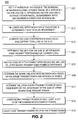
- Figure 2 illustrates diagrammatically a second embodiment in the form of a flow chart.
- the transmit power range lies between the upper bound and lower bound of the transmit power of a particular code.
- the method of the present invention determines an appropriate transmit power range (especially the upper bound) for each code so that when the transmit power of any code approaches its upper bound, the transmit power of other codes can be adjusted to stay within the dynamic range.
- the solution of two present inventions determines the range of code transmit power using at least some of the following parameters: 1) number of codes in the downlink (time slot, if TDD); 2) the range of the SIR target of the code; 3) the maximum allowed dynamic range of the receiver used at the UE (dynamic power range of the receiver is the maximum allowed difference between transmit power of any codes); 4) average MUD efficiency factor in the downlink (for TDD only); 5) average orthogonal factor in the downlink (for FDD only); 6) average inter-cell to intra-cell interference ratio.
- the inventive method permits cellular networks to determine the dynamic range of code transmit power in the downlink power control.
- it is applicable to all modes of UMTS systems (including FDD, HCR TDD, and LCR TDD).
- the method 100 of the first embodiment, shown in Figure 1, uses the following information to determine the range of code transmit-power:
- N The number of codes in the downlink (time slot, if TDD), denoted by N , at step S1 is obtained;
- the range of the SIR target of the code i is then obtained (step S2).
- the range is determined by the C-RNC from the BLER requirement of service and possible propagation conditions.
- the upper bound is the SIR target corresponding to the SIR in the worst case (known as case 1 in the technical literature) and the lower bound is the SIR target corresponding to the best case (known as the AWGN case in the technical literature); and
- DR The maximum allowed dynamic range of the receiver used at the UE is DR, the value of which depends on the design of the receiver. Therefore, DR is a design parameter that can be configured by the operator.
- the code transmit power range is determined as follows. First, among all the codes, the code with maximum upper bound SIR target, say code j , is selected (step S3).
- the upper bound of the transmit power of code i is denoted by TXCode ub ( i ) which is used as a reference.
- the relationship between the upper bound of code transmit power of code i and code j (the code with maximum upper bound SIR target), obtained at step S4, is expressed as:
- TXCode u ⁇ b i R i ⁇ T ⁇ X ⁇ Code ub j
- R ( i ) the desired ratio between TXCode ub ( i ) and TXCode ub ( j ) , is
- R i ⁇ SIR ub i SIR ub j i ⁇ f ⁇ SIR ub j SIR ub i ⁇ D ⁇ R 1 D ⁇ R i ⁇ f ⁇ SIR ub j SIR ub i > D ⁇ R
- the sum of upper bound of code transmit power is subject to the limit of maximum Node B carrier power, CATX max , (step S5).
- a margin is used to prevent the total code transmit-power to reach the maximum allowed value.
- the margin a design parameter, can be configured by the operator as:
- the lower bound of code transmit power, obtained at step S6, is set to the minimum allowed carrier power of the Node B.
- the code transmit powers are then adjusted to lie within the dynamic range (step S7).
- the method 100 will configure or reconfigure the range of code transmit power whenever the number of codes in the downlink changes, which includes: radio link setup for a new CCTrCH and radio link release for an existing CCTrCH. Accordingly, the method 100 is suitable for a real-time services scenario, where the number of codes changes relatively slowly.
- a second embodiment of a method 200 in accordance with the present invention uses the following information to determine the range of code transmit power: 1) the number of codes in the downlink (time slot, if TDD), denoted by N ; 2) the range of SIR target of the code i: the lower bound SIR lb ( i ) and upper bound SIR ub ( i ) which are determined from the BLER requirement; 3) the maximum allowed dynamic range of receiver used at the UE, DR ; 4) average MUD efficiency factor in the downlink (for TDD only), ⁇ ; 5) average orthogonal factor in the downlink (for FDD only), ⁇ ; 6) average inter-cell to intra-cell interference ratio, ⁇ ; and 7) maximum allowed load in the downlink, Load max .
- This is a design parameter that can be configured by the operator and executed by the call admission control function.
- Code transmit power range is then determined as follows: The current load in the downlink (time slot, if TDD) is computed (S 13). Among all the codes, the code with maximum upper bound SIR target, say code j , is selected (step S14).
- the load in the downlink is controlled by the call admission control function to be no more than the maximum allowed load in the downlink, Load max .
- the limit for the sum of code transmit power upper bounds, obtained at step S14, is set to be proportional to the current load. That is:
- the upper bound of the transmit power of code i is TXCode ub ( i ) .
- the relationship between the upper bound of code transmit power of code i and code j is expressed as:
- TXCode u ⁇ b i R i ⁇ TXCode u ⁇ b j
- R ( i ) the desired ratio between TXCode ub ( i ) and TXCode ub ( j ) , (obtained at step S16), is:
- R i ⁇ SIR ub i SIR ub j i ⁇ f ⁇ SIR ub j SIR ub i ⁇ D ⁇ R 1 D ⁇ R i ⁇ f ⁇ SIR ub j SIR ub i > D ⁇ R
- equation 14 utilizing equation 14 in equation 10 provides:
- the lower bound of the code transmit power (obtained at step S18), is set to be the minimum allowed carrier power of the Node B as:
- the code transmit powers are then adjusted to lie within the dynamic range (step S19).
- the method 200 shown in Figure 2 does not necessarily need to configure or reconfigure the range of code transmit power when the number of codes in the downlink changes.
- the transmit power range for a code is determined by its SIR upper bound and maximum SIR upper bound of codes in the downlink (time slot, if TDD).
- the maximum SIR upper bound of codes in the downlink does not change the value of R ( i ) ⁇ SIR ub ( j )
- the range of code transmit power will not change.
- the frequency of reconfiguration of the code transmit power range is much less than the frequency at which the number of codes changes. Therefore, this algorithm is suitable for a non-real-time services scenario, where the number of codes changes quickly. In addition, it is also suitable for a real-time services scenario as well.
- the flow diagram of Figure 1 shows the preferred sequence of operations for implementing the first algorithm. Initially, the number of the codes in the downlink and the maximum allowed dynamic range are obtained, followed by steps which operate on the data obtained to achieve the desired result. However, the steps may be altered in sequence without departing from the scope of the invention.
- the flow diagram of Figure 2 shows the preferred sequence of operations for implementing the second algorithm.
- the process initially obtains the number of codes in the downlink, the maximum allowed dynamic range, MUD efficiency factor (as applied to TDD only), orthogonal factor (as applied to FDD only), average inter-intracell interference ratio, and maximum allowed load in downlink, followed by operations on these data to achieve the desired result.
- MUD efficiency factor as applied to TDD only
- orthogonal factor as applied to FDD only
- average inter-intracell interference ratio average inter-intracell interference ratio
- maximum allowed load in downlink followed by operations on these data to achieve the desired result.
- the steps may be altered in sequence without departing from the scope of the invention.
Landscapes
- Engineering & Computer Science (AREA)
- Computer Networks & Wireless Communication (AREA)
- Signal Processing (AREA)
- Mobile Radio Communication Systems (AREA)
Abstract
Description
- FIELD OF THE INVENTION
- This invention generally relates to cellular networks and more particularly to determination of code transmit power for use in power control.
- BACKGROUND OF THE INVENTION
- For a Universal Mobile Telecommunication System (UMTS) system, in the downlink there are a plurality of different codes transmitted for a plurality of different coded Composite Transport Channels (CCTrCHs) transmitting. Each CCTrCH is power controlled independently. At the receiver of the UE (a RAKE receiver is used for frequency division duplex (FDD), a multi-user detector (MUD) receiver is used for time division duplex (TDD)), the difference between the transmit power of two codes in the same cell has to be within a certain range to assure that the receiver works properly. The maximum allowed difference is called the dynamic range of the receiver. Because the total transmit power (i.e., carrier power) in the downlink is limited, an appropriate range of transmit power for each code should be determined to allow the power control to adjust the difference of code transmit powers to be in the dynamic range as much as possible.
- Currently, there is no known convenient algorithm to determine the range of transmit power for each code in the downlink. The consequence of this is that the transmit power of one code can be increased to a very high value by the power control, which makes it difficult for the transmit power of other codes to catch up with the dynamic range due to the limit of Node B total transmitter power.
- It is desirable to provide a method for determining the range of transmit power in the downlink, preferably in the form of an algorithm.
- SUMMARY OF THE INVENTION
- The invention provides a method and apparatus employing an algorithm for determining the range of transmit power for each code in the downlink properly for all modes of UMTS systems (including FDD, high chip rate (HCR) TDD, and low chip rate (LCR) TDD). In a preferred embodiment, the invention provides details of the preferred implementation. While the following description makes reference to downlink power control for CDMA systems as an example, it is to be noted that the invention is applicable for uplink power control and is also usable in cellular systems other than those mentioned above.
- BRIEF DESCRIPTION OF THE DRAWINGS
- A more detailed understanding of the invention may be had from the following description of preferred embodiments, given by way of example and to be understood in conjunction with the accompanying drawing wherein:
- Figure 1 illustrates diagrammatically a first embodiment in the form of a flow chart for determination of code transmit power range in downlink; and
- Figure 2 illustrates diagrammatically a second embodiment in the form of a flow chart.
- The following acronyms are used in the present application:
- AWGN
- additive white Gaussian noise
- BLER
- block error rate
- CCTrCH
- coded composite transport channel
- CDMA
- code-division multiple access
- CRNC
- controlling RNC
- DR
- dynamic range
- FDD
- frequency-division duplex
- HCR
- high chip rate
- LCR
- low chip rate
- MUD
- multi-user detector
- RNC
- radio network controller
- SIR
- signal to interference ratio
- TDD
- time-division duplex
- UE
- user equipment
- UMTS
- universal mobile telecommunications system
- DETAILED DESCRIPTION OF PREFERRED EMBODIMENTS
- Described hereinafter are a method and apparatus employing algorithms in one of the first and second embodiments for determination of code transmit power for downlink power control in cellular networks. The transmit power range lies between the upper bound and lower bound of the transmit power of a particular code. The method of the present invention determines an appropriate transmit power range (especially the upper bound) for each code so that when the transmit power of any code approaches its upper bound, the transmit power of other codes can be adjusted to stay within the dynamic range.
- The solution of two present inventions determines the range of code transmit power using at least some of the following parameters: 1) number of codes in the downlink (time slot, if TDD); 2) the range of the SIR target of the code; 3) the maximum allowed dynamic range of the receiver used at the UE (dynamic power range of the receiver is the maximum allowed difference between transmit power of any codes); 4) average MUD efficiency factor in the downlink (for TDD only); 5) average orthogonal factor in the downlink (for FDD only); 6) average inter-cell to intra-cell interference ratio.
- The inventive method permits cellular networks to determine the dynamic range of code transmit power in the downlink power control. In particular, it is applicable to all modes of UMTS systems (including FDD, HCR TDD, and LCR TDD).
- The
method 100 of the first embodiment, shown in Figure 1, uses the following information to determine the range of code transmit-power: - The number of codes in the downlink (time slot, if TDD), denoted by N, at step S1 is obtained;
- The range of the SIR target of the code i: the lower bound SIRlb (i) and upper bound SIRub (i), is then obtained (step S2). The range is determined by the C-RNC from the BLER requirement of service and possible propagation conditions. For example, the upper bound is the SIR target corresponding to the SIR in the worst case (known as
case 1 in the technical literature) and the lower bound is the SIR target corresponding to the best case (known as the AWGN case in the technical literature); and - The maximum allowed dynamic range of the receiver used at the UE is DR, the value of which depends on the design of the receiver. Therefore, DR is a design parameter that can be configured by the operator.
- The code transmit power range is determined as follows. First, among all the codes, the code with maximum upper bound SIR target, say code j, is selected (step S3). The upper bound of the transmit power of code i is denoted by TXCodeub (i) which is used as a reference. The relationship between the upper bound of code transmit power of code i and code j (the code with maximum upper bound SIR target), obtained at step S4, is expressed as:
-

- where R(i), the desired ratio between TXCodeub (i) and TXCodeub (j), is
-

- The sum of upper bound of code transmit power is subject to the limit of maximum Node B carrier power, CATX max, (step S5). For system stability purposes, a margin is used to prevent the total code transmit-power to reach the maximum allowed value. The margin, a design parameter, can be configured by the operator as:
-

- Therefore, the upper bound of the transmit power of code i is given by
-

- The lower bound of code transmit power, obtained at step S6, is set to the minimum allowed carrier power of the Node B.
-

- The code transmit powers are then adjusted to lie within the dynamic range (step S7). The
method 100 will configure or reconfigure the range of code transmit power whenever the number of codes in the downlink changes, which includes: radio link setup for a new CCTrCH and radio link release for an existing CCTrCH. Accordingly, themethod 100 is suitable for a real-time services scenario, where the number of codes changes relatively slowly. - A second embodiment of a
method 200 in accordance with the present invention, shown in Figure 2, uses the following information to determine the range of code transmit power: 1) the number of codes in the downlink (time slot, if TDD), denoted by N ; 2) the range of SIR target of the code i: the lower bound SIRlb (i) and upper bound SIRub (i) which are determined from the BLER requirement; 3) the maximum allowed dynamic range of receiver used at the UE, DR; 4) average MUD efficiency factor in the downlink (for TDD only), α ; 5) average orthogonal factor in the downlink (for FDD only), α ; 6) average inter-cell to intra-cell interference ratio, η; and 7) maximum allowed load in the downlink, Load max . This is a design parameter that can be configured by the operator and executed by the call admission control function. These data are obtained at steps S11 and S12. - Code transmit power range is then determined as follows: The current load in the downlink (time slot, if TDD) is computed (S 13). Among all the codes, the code with maximum upper bound SIR target, say code j, is selected (step S14).
- The load contributed by each code i is given by:
-

-

Therefore, the total load is given by: -

- The load in the downlink is controlled by the call admission control function to be no more than the maximum allowed load in the downlink, Load max. The limit for the sum of code transmit power upper bounds, obtained at step S14, is set to be proportional to the current load. That is:
-

-

- The upper bound of the transmit power of code i is TXCodeub (i). The relationship between the upper bound of code transmit power of code i and code j (the code with the maximum upper bound SIR target, obtained at step S15), is expressed as:
-

- Where R(i), the desired ratio between TXCodeub (i) and TXCodeub (j), (obtained at step S16), is:
-

- Therefore, the upper bound of transmit power of code i, (obtained at step S17), is given by:
-

- Utilizing equation 12 in equations 6-8, the result is:
-

- Likewise, utilizing
equation 14 in equation 10 provides: -

- Finally, utilizing 15 in equation 13 yields:
-

- The lower bound of the code transmit power (obtained at step S18), is set to be the minimum allowed carrier power of the Node B as:
-

- The code transmit powers are then adjusted to lie within the dynamic range (step S19).
- The
method 200 shown in Figure 2 does not necessarily need to configure or reconfigure the range of code transmit power when the number of codes in the downlink changes. As shown inequation 16, the transmit power range for a code is determined by its SIR upper bound and maximum SIR upper bound of codes in the downlink (time slot, if TDD). As long as the maximum SIR upper bound of codes in the downlink (time slot, if TDD) does not change the value of R(i)·SIRub (j), the range of code transmit power will not change. As a result, the frequency of reconfiguration of the code transmit power range is much less than the frequency at which the number of codes changes. Therefore, this algorithm is suitable for a non-real-time services scenario, where the number of codes changes quickly. In addition, it is also suitable for a real-time services scenario as well. - The flow diagram of Figure 1 shows the preferred sequence of operations for implementing the first algorithm. Initially, the number of the codes in the downlink and the maximum allowed dynamic range are obtained, followed by steps which operate on the data obtained to achieve the desired result. However, the steps may be altered in sequence without departing from the scope of the invention.
- The flow diagram of Figure 2 shows the preferred sequence of operations for implementing the second algorithm. The process initially obtains the number of codes in the downlink, the maximum allowed dynamic range, MUD efficiency factor (as applied to TDD only), orthogonal factor (as applied to FDD only), average inter-intracell interference ratio, and maximum allowed load in downlink, followed by operations on these data to achieve the desired result. Here too, the steps may be altered in sequence without departing from the scope of the invention.
- Even though the above description makes reference to FDD and TDD systems as examples, the invention for downlink power control is applicable to other types of communication systems as well.
-
- 1. A method for determining code transmit power in a time division duplex communication system, comprising:
- a) obtaining a number of codes in a downlink and a maximum allowed dynamic range;
- b) determining an upper bound and a lower bound of a signal to interference ratio (SIR) of each code based on a block error rate (BLER) requirement;
- c) computing a load contributed by each code;
- d) summing the load to obtain a current total load;
- e) determining a limit for a sum of upper bound code transmit power based on a current load;
- f) determining a code with the highest upper bound SIR;
- g) employing the upper bound code transmit power of the code having the highest upper bound SIR;
- h) determining a desired relative ratio between the upper bound code transmit power of each code and a reference;
- i) determining the upper bound transmit power of each code based on a sum of the upper bound code transmit power; and
- j) setting a lower bound transmit power for each code based on a minimum Node B carrier power.
- 2. The method of
item 1, further comprising:- adjusting code transmit powers to lie within a dynamic range.
- 3. The method of
item 1, wherein step (a) further comprises:- obtaining a multi-user detector (MUD) efficiency factor and average inter-intracell interference ratio and a maximum allowed load in downlink.
- 4. The method of
item 1, wherein step (b) further includes selecting an SIR target corresponding to an SIR in a worst case as the upper bound. - 5. The method of
item 1, wherein step (b) further includes selecting an SIR target corresponding to an SIR in a best case. - 6. A method for determining code transmit power in a frequency division duplex communication system, comprising:
- a) obtaining a number of codes in a downlink and a maximum allowed load in the downlink;
- b) determining an upper bound and a lower bound of a signal to interference ratio (SIR) of each code based on a block error rate (BLER) requirement;
- c) computing a load contributed by each code;
- d) summing the load to obtain a current total load;
- e) determining a limit for a sum of upper bound code transmit power based on a current load;
- f) determining a code with a highest upper bound SIR;
- g) employing the upper bound code transmit power of the code having the highest upper bound SIR;
- h) determining a desired relative ratio between the upper bound code transmit power of each code and a reference;
- i) determining the upper bound transmit power of each code based on a sum of the upper bound code transmit power; and
- j) setting a lower bound transmit power for each code based on a minimum Node B carrier power.
- 7. The method of item 6, further comprising:
- adjusting code transmit powers to lie within a dynamic range.
- 8. The method of item 6, wherein step (a) further comprises:
- obtaining a maximum allowed dynamic range, an orthogonal factor, and an average inter-intracell interference ratio.
- 9. The method of item 6, wherein step (b) further includes selecting an SIR target corresponding to an SIR in a worst case as the upper bound.
- 10. The method of item 6, wherein step (b) further includes selecting an SIR target corresponding to an SIR in a best case.
- 11. A method for determining code transmit power, comprising:
- a) obtaining a number of codes in a downlink in a maximum allowed dynamic range;
- b) determining a lower bound and an upper bound signal-to-interference ratio (SIR) of each code based on a block error rate (BLER) criteria;
- c) determining a code with a highest upper bound SIR and establishing its upper bound transmit code power as a reference;
- d) determining a desired relative ratio between each code upper bound transmit power and the reference;
- e) determining an upper bound transmit power of each code based on a constraint of a maximum Node B carrier power; and
- f) setting a lower bound transmit power for each code at a minimum Node B carrier power.
- 12. The method of item 11, wherein step (b) further includes selecting an SIR target corresponding to an SIR in a worst case as the upper bound.
- 13. The method of item 11, wherein step (b) further includes selecting an SIR target corresponding to an SIR in a best case.
- 14. Apparatus for determining code transmit power in a time division duplex communication system comprising:
- means for obtaining a number of codes in a downlink and a maximum allowed load in the downlink;
- means for determining an upper bound and a lower bound of a signal to interference ratio (SIR) of each code based on a block error rate (BLER) requirement;
- means for computing a load contributed by each code;
- means for summing the load to obtain a current total load;
- means for determining a limit for a sum of upper bound code transmit power based on the current load;
- means for determining a code with the highest upper bound SIR;
- means for employing the upper bound code transmit power of the code having the highest upper bound SIR;
- means for determining a desired relative ratio between each code upper bound transmit power and a reference;
- means for determining an upper bound transmit power of each code based on a sum of the upper bound code transmit power; and
- means for setting a lower bound transmit power for each code based on a minimum Node B carrier power.
- 15. The apparatus of
item 14, further comprising:- means for adjusting the code transmit powers to lie within a dynamic range.
- 16. The apparatus of
item 14, wherein said means for obtaining further comprises:- means for obtaining a maximum allowed dynamic range, a multiple user detector (MUD) efficiency factor, and an average inter-intracell interference ratio.
- 17. Apparatus for determining code transmit power in a frequency division duplex communication system, comprising:
- means for obtaining a number of codes in a downlink and a maximum allowed load in downlink;
- means for determining an upper bound and a lower bound of a signal to interference ratio (SIR) of each code based on a block error rate (BLER) requirement;
- means for computing a load contributed by each code;
- means for summing the load to obtain a current total load;
- means for determining a limit for a sum of upper bound code transmit power based on the current load;
- means for determining a code with the highest upper bound SIR;
- means for employing the upper bound code transmit power of the code having the highest upper bound SIR;
- means for determining a desired relative ratio between the code upper bound transmit power of each code and a reference;
- means for determining the upper bound transmit power of each code based on a sum of the upper bound code transmit power; and
- means for setting a lower bound transmit power for each code based on a minimum Node B carrier power.
- 18. The apparatus of
item 17, further comprising:- means for adjusting the code transmit powers to lie within a dynamic range.
- 19. The apparatus of
item 17, wherein said means for obtaining further comprises:- means for obtaining a maximum allowed dynamic range, an orthogonal factor and an average inter-intracell interference ratio.
- 20. Apparatus for determining code transmit power, comprising:
- means for obtaining a number of codes in a downlink in a maximum allowed dynamic range;
- means for determining a lower bound and an upper bound signal-to-interference ratio (SIR) of each code based on a block error rate (BLER) criteria;
- means for determining the code with a highest upper bound SIR and establishing its upper bound transmit code power as a reference;
- means for determining a desired relative ratio between the upper bound code transmit power of each code and the reference;
- means for determining an upper bound transmit power of each code based on a constraint of a maximum Node B carrier power; and
- means for setting a lower bound transmit power for each code at a minimum Node B carrier power.
Claims (16)
- A method for determining code transmit power in a frequency division duplex communication system, comprising:a) obtaining a number of codes in a downlink and a maximum allowed load in the downlink;b) determining an upper bound and a lower bound of a signal to interference ratio, SIR, of each code based on a block error rate, BLER, requirement;c) computing a load contributed by each code;d) summing each load computed at step (c) to obtain a current total load;e) determining a limit for a sum of upper bound code transmit power based on a current load;f) determining a code with a highest upper bound SIR;g) employing the code determined at step (f) as a reference;h) determining a desired relative ratio between the upper bound code transmit power of each code and said reference;i) determining the upper bound transmit power of each code based on a sum of the upper bound code transmit power; andj) setting a lower bound transmit power for each code based on a minimum Node-B carrier power.
- The method of claim 1, further comprising:adjusting code transmit powers to lie within a dynamic range.
- The method of claim 1, wherein step (a) further comprises:obtaining a maximum allowed dynamic range, an orthogonal factor, and an average inter-intracell interference ratio.
- The method of claim 1, wherein step (b) further includes selecting an SIR target corresponding to an SIR in a worst case as the upper bound.
- The method of claim 1, wherein step (b) further includes selecting an SIR target corresponding to an SIR in a best case.
- The method of claim 1 wherein step (b) further comprises:determining the range of SIR target of each code.
- The method of claim 1 wherein step (a) further comprises:for time division duplex, TDD, determining an average multi-user detector, MUD efficiency factor in the downlink.
- The method of claim 1 wherein step (a) further comprises:determining a maximum allowed dynamic range of a receiver at a user equipment, UE.
- The method of claim 8 wherein the orthogonal factor obtained is an average orthogonal factor.
- Apparatus for determining code transmit power in a frequency division duplex communication system, comprising:first means for obtaining a number of codes in a downlink and a maximum allowed load in downlink;second means for determining an upper bound and a lower bound of a signal to interference ratio, SIR, of each code based on a block error rate, BLER, requirement;third means for computing a load contributed by each code;fourth means for summing the loads computed by the third means to obtain a current total load;fifth means for determining a limit for a sum of upper bound code transmit power based on the current load;sixth means for determining a code with the highest upper bound SIR;seventh means for employing the code determined by said sixth means as a reference;eighth means for determining a desired relative ratio between the code upper bound transmit power of each code and said reference;ninth means for determining the upper bound transmit power of each code based on a sum of the upper bound code transmit power; andtenth means for setting a lower bound transmit power for each code based on a minimum Node B carrier power.
- The apparatus of claim 10, further comprising:eleventh means for adjusting the code transmit powers to lie within a dynamic range.
- The apparatus of claim 10, wherein said first means further comprises:means for obtaining a maximum allowed dynamic range, an orthogonal factor and an average inter-intracell interference ratio.
- The apparatus of claim 10 wherein said second means further comprises:means for determining the range of SIR target of each code.
- The apparatus of claim 10 wherein said first means further comprises:for time division duplex, TDD, means for determining an average multi-user detector, MUD, efficiency factor in the downlink.
- The apparatus of claim 10 wherein said first means further comprises:means determining a maximum allowed dynamic range of a receiver at a user equipment, UE.
- The apparatus of claim 15 wherein the orthogonal factor obtained by said first means is an average orthogonal factor.
Applications Claiming Priority (2)
| Application Number | Priority Date | Filing Date | Title |
|---|---|---|---|
| US41593802P | 2002-10-03 | 2002-10-03 | |
| EP03776223A EP1550237B1 (en) | 2002-10-03 | 2003-10-02 | Determination of code transmit power range in downlink power control for cellular systems |
Related Parent Applications (1)
| Application Number | Title | Priority Date | Filing Date |
|---|---|---|---|
| EP03776223A Division EP1550237B1 (en) | 2002-10-03 | 2003-10-02 | Determination of code transmit power range in downlink power control for cellular systems |
Publications (1)
| Publication Number | Publication Date |
|---|---|
| EP1860786A1 true EP1860786A1 (en) | 2007-11-28 |
Family
ID=38621861
Family Applications (1)
| Application Number | Title | Priority Date | Filing Date |
|---|---|---|---|
| EP07116169A Withdrawn EP1860786A1 (en) | 2002-10-03 | 2003-10-02 | Determination of code transmit power range in downlink power control for cellular systems. |
Country Status (1)
| Country | Link |
|---|---|
| EP (1) | EP1860786A1 (en) |
Citations (1)
| Publication number | Priority date | Publication date | Assignee | Title |
|---|---|---|---|---|
| WO2001071932A1 (en) * | 2000-03-21 | 2001-09-27 | Matsushita Electric Industrial Co., Ltd. | Transmission device |
-
2003
- 2003-10-02 EP EP07116169A patent/EP1860786A1/en not_active Withdrawn
Patent Citations (2)
| Publication number | Priority date | Publication date | Assignee | Title |
|---|---|---|---|---|
| WO2001071932A1 (en) * | 2000-03-21 | 2001-09-27 | Matsushita Electric Industrial Co., Ltd. | Transmission device |
| US20030076790A1 (en) * | 2000-03-21 | 2003-04-24 | Katsuhiko Hiramatsu | Transmission device |
Similar Documents
| Publication | Publication Date | Title |
|---|---|---|
| US7106700B2 (en) | Method of controlling quality of service of CDMA system using dynamic adjustment of parameters representing transmitting properties concerning quality of service | |
| US7483404B2 (en) | Power control for mobile station in a CDMA-TDD system | |
| US8761124B2 (en) | Apparatus and methods for determination of gain factors for wireless communication transmission power | |
| EP1089458B1 (en) | Radio telecommunications network | |
| EP1780905A1 (en) | Method and apparatus for distributed reverse link scheduling of rate and power in a wireless communication system | |
| KR100790923B1 (en) | Dynamic Radio Link Adaptation to Interference in Cellular Systems | |
| US20050099973A1 (en) | Base station and transmission power determining method in mobile communications systems | |
| US20020001292A1 (en) | Downlink power control method and CDMA communication system incorporating the control method | |
| US7808944B2 (en) | Wireless communication method and apparatus for controlling the transmission power of downlink and uplink coded composite transport channels based on discontinuous transmission state values | |
| EP1550237B1 (en) | Determination of code transmit power range in downlink power control for cellular systems | |
| US7206296B2 (en) | Transmitting device and transmitting method | |
| US20040058685A1 (en) | Allocation of shared channel data rates in a communication system | |
| JP4186212B2 (en) | Method and apparatus for variable rate communication at high transmission rate |
Legal Events
| Date | Code | Title | Description |
|---|---|---|---|
| PUAI | Public reference made under article 153(3) epc to a published international application that has entered the european phase |
Free format text: ORIGINAL CODE: 0009012 |
|
| 17P | Request for examination filed |
Effective date: 20070911 |
|
| AC | Divisional application: reference to earlier application |
Ref document number: 1550237 Country of ref document: EP Kind code of ref document: P |
|
| AK | Designated contracting states |
Kind code of ref document: A1 Designated state(s): AT BE BG CH CY CZ DE DK EE ES FI FR GB GR HU IE IT LI LU MC NL PT RO SE SI SK TR |
|
| AX | Request for extension of the european patent |
Extension state: AL BA HR MK YU |
|
| 17Q | First examination report despatched |
Effective date: 20080626 |
|
| AKX | Designation fees paid |
Designated state(s): AT BE BG CH CY CZ DE DK EE ES FI FR GB GR HU IE IT LI LU MC NL PT RO SE SI SK TR |
|
| STAA | Information on the status of an ep patent application or granted ep patent |
Free format text: STATUS: THE APPLICATION IS DEEMED TO BE WITHDRAWN |
|
| 18D | Application deemed to be withdrawn |
Effective date: 20081107 |