EP1089458B1 - Radio telecommunications network - Google Patents
Radio telecommunications network Download PDFInfo
- Publication number
- EP1089458B1 EP1089458B1 EP99310301A EP99310301A EP1089458B1 EP 1089458 B1 EP1089458 B1 EP 1089458B1 EP 99310301 A EP99310301 A EP 99310301A EP 99310301 A EP99310301 A EP 99310301A EP 1089458 B1 EP1089458 B1 EP 1089458B1
- Authority
- EP
- European Patent Office
- Prior art keywords
- ctrl
- tfc
- dpcch
- bits
- levels
- Prior art date
- Legal status (The legal status is an assumption and is not a legal conclusion. Google has not performed a legal analysis and makes no representation as to the accuracy of the status listed.)
- Expired - Lifetime
Links
Images

Classifications
-
- H—ELECTRICITY
- H04—ELECTRIC COMMUNICATION TECHNIQUE
- H04W—WIRELESS COMMUNICATION NETWORKS
- H04W52/00—Power management, e.g. TPC [Transmission Power Control], power saving or power classes
- H04W52/04—TPC
- H04W52/30—TPC using constraints in the total amount of available transmission power
- H04W52/32—TPC of broadcast or control channels
-
- H—ELECTRICITY
- H04—ELECTRIC COMMUNICATION TECHNIQUE
- H04W—WIRELESS COMMUNICATION NETWORKS
- H04W52/00—Power management, e.g. TPC [Transmission Power Control], power saving or power classes
- H04W52/04—TPC
- H04W52/06—TPC algorithms
- H04W52/16—Deriving transmission power values from another channel
-
- H—ELECTRICITY
- H04—ELECTRIC COMMUNICATION TECHNIQUE
- H04W—WIRELESS COMMUNICATION NETWORKS
- H04W52/00—Power management, e.g. TPC [Transmission Power Control], power saving or power classes
- H04W52/04—TPC
- H04W52/18—TPC being performed according to specific parameters
- H04W52/26—TPC being performed according to specific parameters using transmission rate or quality of service QoS [Quality of Service]
Definitions
- This invention relates to radio telecommunications networks in which mobile stations communicate with base stations in dedicated physical data channels (DPDCHs) and dedicated physical control channels (DPCCHs), in which transmit power levels in the DPDCHs are set in releation to the transmit power level in the DPCCH by a power offset factor G.
- DPDCHs dedicated physical data channels
- DPCCHs dedicated physical control channels
- G transmit power levels in the DPDCHs are set in releation to the transmit power level in the DPCCH by a power offset factor G.
- G power offset factor
- UMTS universal mobile telecommunications systems
- the DPDCH carries data of the Dedicated Channels (DCH), i.e. either transmitted user traffic or higher layer control information and the DPCCH carries physical layer control information, i.e. pilot symbols, transmission power control (TPC) bits and the transport format indicator (TFCI).
- DCH Dedicated Channels
- TPC transmission power control
- TFCI transport format indicator
- the (E b /N 0 ) ctrl of the DPCCH is adjusted by the power control (PC) procedures (closed loop, outer loop PC). But it is the E b /N 0 of each DCH that determines the Quality of Service (QoS) of each Radio Access Bearer (RAB) and hence E b /N 0 should be controlled by the PC.
- PC power control
- G power offset factor G between DPCCH and DPDCH defined in the 3GPP standards (3GPP UMTS TS 25.213: "Spreading and modulation (FDD)").
- the value of G should be adjusted in such a way that the ratio of bit energy to background noise density (E b /N 0 ), and hence the transmission power requirements, of the DPCCH and the DPDCH, are met without wasting too much power.
- E b /N 0 the ratio of bit energy to background noise density
- DPDCHs dedicated physical data channels
- DPCCH dedicated physical control channel
- the relation between the (E b /N 0 ) ctrl of the DPCCH and the E b /N 0 of each DCH varies depending on the currently used mix of data rates of the DCH which is given by the Transport Format Combination (TFC).
- TFC Transport Format Combination
- a preferred embodiment of the invention therefore includes a stored table of values of (E b /N 0 ) l for different combinations of class of service, spreading factor and rate matching levels, the value of (E b /N 0 ) i used to set the transmit power level in the DPDCH being selected according to the spreading factor and the rate matching level resulting from a selected traffic format combination (TFC) /.
- the power offset G could, perhaps, be adjusted by the transmitting side (UE or NodeB) autonomously. However there are some reasons to not allow the transmitting side to calculate the value of G by itself:
- the transmitter has to decide by itself about the used power offset then the E b /N 0 values for all services has to be known. They are not only dependent on the service but also on the despreading and decoding method in the receiver (manufacturer dependent), the environment etc.
- the receiving side For decoding (e.g. normalizing the channel estimate) the receiving side has to know the G, too. If G is calculated autonomously in the transmitter the same value has to be calculated also in the receiver. Due to different calculation methods, e.g. different accuracy there might be different results in transmitter and receiver.
- the algorithm has to be standardized. This limits the flexibility for enhancing of the algorithms.
- the contents of the table is sent to the mobile station and to the base station from a radio network controller (RNC), the mobile station and the base station being operative to calculate the spreading factor and rate matching levels resulting from a desired TFC, to select the (E b N 0 )s appropriate to the classes of service, the spreading factor and the rate matching levels, and to calculate the respective amplitude factor G.
- RNC radio network controller
- the network deals with the problem of assigning the power offset between DPCCH and DPDCH.
- the problem arises from the usage of power control on the DPCCH whereas the quality that is under control (e.g. BER) is given on the DCH/DPDCH.
- the power is adjusted in such a way that the transmission power requirements of the DPCCH and the DPDCH are met without wasting too much power.
- An algorithm for assigning the power offsets consists of two main parts:
- This algorithm allows efficient setting of dynamically variable offset values without too much signalling overhead. It is compliant to the currently UMTS standard.
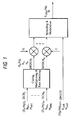
- the UMTS physical layer model for the uplink and for the downlink is depicted in FIG. 2 .
- the DCH of one user are coded and multiplexed into one or several DPDCH. Additional rate matching is applied to balance the E b /N 0 requirements of different DCH.
- the DPDCH are weighted by an amplitude factor G, multiplexed with the DPCCH and spread to a chip rate W.
- DCH i is described by (E b /N 0 ) i and data rate R bi .
- the number of bits (transport block set size) is N biti .
- All DPDCH have the same E s /N 0 and the same symbol rate R S .
- the number of symbols is N S .
- the number of used multi-codes is m.
- the DPCCH is described by (E B /N 0 ) ctrl and control bit rate R ctrl .
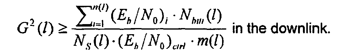
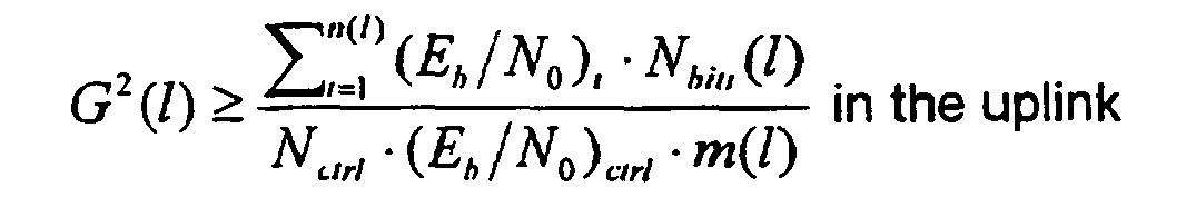
- the power control adjusts the transmission power on the DPCCH and hence (E B /N 0 ) ctrl . If the power offset factor G between DPDCH and DPCCH is chosen that eq. (4) (uplink) or eq. (6) (downlink) is fulfilled for every combination of N biti (TFCI) the value of (E B /N 0 ) ctrl remains constant even in the case of variable data rates without any extra signalling beyond TFCI.
- Figure 2 gives an overview of the proposed rate matching algorithm. It consists of two main parts, which are defined as follows:
- Radio Resource Control function that is located in the Radio Network Controler (RNC) for both uplink as well as downlink.
- Layer 1 functions that are located in the transmitter side, i.e. in the NodeB for the downlink and in the UE for the uplink, and in the receiving side, i.e. the UE for the downlink and the NodeB for the uplink.
- the power assignment algorithm is as follows:
- Inputs to the algorithm are the required (E b /N 0 ) i for each DCH i and the number of data bits per data frame N biti (l) of DCH i for each transport format combination TFC(I).
- the number of symbols N S (l) and the number of DPDCH (i.e. multicodes) m(I) is also known.
- the number of control bits N ctrl is assumed fixed.
- the (E b /N 0 ) ctrl of the DPCCH is determined by the required BER of e.g. the TPC or TFCI bits. It depends on several conditions, e.g. whether the UE is in soft handoff.
- the power offsets G(I) for each TFC(I) will be determined.
- G 2 l ⁇ ⁇ i 1 n l E b / N 0 i ⁇ N bits l N ctrl ⁇ E b / N 0 ctrl ⁇ m l in the uplink
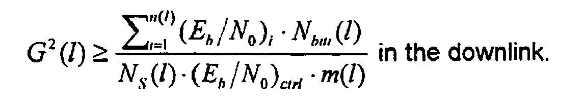
- G 2 l ⁇ ⁇ i 1 n l E b / N 0 i ⁇ N bits l N S l ⁇ E b / N 0 ctrl ⁇ m l in the downlink .
- Either a complete set of values of G for all TFCs can be sent to the mobile station and the RNC or a complete table of E b /N 0 for all TFCs can be sent.
- Discrete values of G(I) may be used to save implementation effort and transmission overhead. Then the next higher valid G(I) must be chosen, which implies a slight waste of transmission power.
- Equal G(I) might be related to different TFC(I).
- the procedure is as follows: At first the TFC(I) that have similar G(I) are grouped into the same group. The number of groups equals or is less than the number of allowed G-values. Then the highest G(I) is taken and connected to the group of TFC. Depending on the number of allowed G(I) there is a higher waste of transmission power.
- the calculated G(I) or table of E b /N 0 will be transmitted to both the transmitting and the receiving side together with the TFC(I) using higher layer signalling. From this point, there is a fixed relation between the TFC(I) and the G(I).
- the physical layer adjusts autonomously the power offset G(I) that is related to the chosen TFC(I) for transmission.
- the ⁇ -factor can be used, but the algorithm is not limited to it. The exact method depends on the implementation.
- the TFC(I) is coded into the transport format combination indicator TFCI that will be transmitted on the DPCCH to the receiving side.
- the physical layer in the receiver From the received TFCI the physical layer in the receiver knows the TFC(I) of the data frame that is currently used. Because inner loop power control adjusts the transmission power in such a way that (E b /N 0 ) ctrl of the DPCCH remains constant the TFCI can be properly decoded even in case of changing the data rate (and TFC) of the DCHs.
- the TFC information will normally be used to decode and demultiplex the data blocks of the DCH currently in use.
- the receiver knows implicitly G(I) from TFC(I) and hence can use this parameter for detection of the transmitted data (e.g. normalizing the channel estimate).
- Variations in the environment e.g. due to soft handover, changes the value of (E b /N 0 ) ctrl of the DPCCH.
- Variations of the user behaviour e.g. changing the TFCS due to RAB procedures changes the values of (E b /N 0 ) l and/ or N biti (I) of DCH i for each TFC(I). Then, the RNC calculates new values G(I) and send them to both, the transmitting and receiving side again via higher layer signalling.
- the power offset assignment algorithm solves the problem of adjusting the power offset between DPCCH and DPDCH. It has the following properties:
- N ctrl1 N pilot
- N ctrl2 N TPC
- N ctrl3 N TFCl .
- the algorithm supports the usage of limited numbers of G-values, e.g. due to quantization or reduced signalling overhead.
Description
- This invention relates to radio telecommunications networks in which mobile stations communicate with base stations in dedicated physical data channels (DPDCHs) and dedicated physical control channels (DPCCHs), in which transmit power levels in the DPDCHs are set in releation to the transmit power level in the DPCCH by a power offset factor G. An example of such as network is the universal mobile telecommunications systems (UMTS).
- In the UMTS example, the DPDCH carries data of the Dedicated Channels (DCH), i.e. either transmitted user traffic or higher layer control information and the DPCCH carries physical layer control information, i.e. pilot symbols, transmission power control (TPC) bits and the transport format indicator (TFCI).
- For implementation reasons the (Eb/N0)ctrl of the DPCCH is adjusted by the power control (PC) procedures (closed loop, outer loop PC). But it is the Eb/N0 of each DCH that determines the Quality of Service (QoS) of each Radio Access Bearer (RAB) and hence Eb/N0 should be controlled by the PC. To solve this issue there is a power offset factor G between DPCCH and DPDCH defined in the 3GPP standards (3GPP UMTS TS 25.213: "Spreading and modulation (FDD)"). Desirably, the value of G should be adjusted in such a way that the ratio of bit energy to background noise density (Eb/N0), and hence the transmission power requirements, of the DPCCH and the DPDCH, are met without wasting too much power. For example a high data rate DPDCH has to be transmitted with a higher transmission power than the low data rate DPCCH.
- Broadly, against this background the invention provides a radio telecommunications network, in which mobile stations communicate with base stations in dedicated physical data channels (DPDCHs) and a dedicated physical control channel (DPCCH), transmit power levels in the DPCCH being controlled by detecting received signal levels in the DPCCH, and transmit power levels in the DPDCHs being set in relation to the transmit power level in the DPCCH for a traffic format combination I, by an amplitude factor G(I) given:

- Where (Eb/N0)i is the ratio of bit energy to background noise density which is required to achieve a class of service dependent desired bit error rate for data channel i
- Nbiti is the number of bits desired to be sent per frame in channel i
- Nctrl is the number of bits per frame in the control channel
- (Eb/N0)ctrl is the ratio of bit energy to background noise density which is required to achieve a desired bit error rate in the control channel
- m(I) is the number of multi-codes;
- Ns(I) is the total number of symbols per frame in the data channel; and n(l) is the total number of data channels for the traffic format combination l in the DPDCH.
- In more detail, the relation between the (Eb/N0)ctrl of the DPCCH and the Eb/N0 of each DCH varies depending on the currently used mix of data rates of the DCH which is given by the Transport Format Combination (TFC). Detailed investigations reveal that there is a fixed relation between G and TFC. Therefore by properly setting of G, the Eb/N0 of the DCH can be controlled using (Eb/N0)ctrl of the DPCCH, too.
- A preferred embodiment of the invention therefore includes a stored table of values of (Eb/N0)l for different combinations of class of service, spreading factor and rate matching levels, the value of (Eb/N0)i used to set the transmit power level in the DPDCH being selected according to the spreading factor and the rate matching level resulting from a selected traffic format combination (TFC) /.
- Since the values of Eb/N0 together with the TFCS are known, the power offset G could, perhaps, be adjusted by the transmitting side (UE or NodeB) autonomously. However there are some reasons to not allow the transmitting side to calculate the value of G by itself:
- If the transmitter has to decide by itself about the used power offset then the Eb/N0 values for all services has to be known. They are not only dependent on the service but also on the despreading and decoding method in the receiver (manufacturer dependent), the environment etc.
- For decoding (e.g. normalizing the channel estimate) the receiving side has to know the G, too. If G is calculated autonomously in the transmitter the same value has to be calculated also in the receiver. Due to different calculation methods, e.g. different accuracy there might be different results in transmitter and receiver.
- In some situations (e.g. soft Handover) other offsets has to be adjusted. This only can be decided in the network.
- If the transmitter can decide the power offset by itself, the algorithm has to be standardized. This limits the flexibility for enhancing of the algorithms.
- Most preferebly, therefore, the contents of the table is sent to the mobile station and to the base station from a radio network controller (RNC), the mobile station and the base station being operative to calculate the spreading factor and rate matching levels resulting from a desired TFC, to select the (EbN0)s appropriate to the classes of service, the spreading factor and the rate matching levels, and to calculate the respective amplitude factor G.
- Reference is made to the following papers:
- 3GPP UMTS TS 25.214: "Physical Layer Procedures (FDD)";
- O. Salonaho, J. Laakso: "Flexible Power Allocation For Physical Control Channel In Wideband CDMA," IEEE VTC'99; and
- Ericsson: "Amplitude differences between uplink DPCCH and DPDCHs," TDoc 3GPP TSG-RAN WG1 347/99
- The invention also extends to a method of operating a radio telecommunications network, in which mobile stations communicate with base stations in dedicated physical data channels (DPDCHs) and a dedicated physical control channel (DPCCH), the method comprising controlling transmit power levels in the DPCCH by detecting received signal levels in the DPCCH, and setting transmit power levels in the DPDCHs in relation to the transmit power level in the DPCCH for a traffic format combination I, by an amplitude factor G(I) given:


- Where (Eb/N0)l is the ratio of bit energy to background noise density which is required to achieve a class of service dependent desired bit error rate for data channel i
- Nbiti is the number of bits desired to be sent per frame in channel i
- Nctrl is the number of bits per frame in the control channel
- (Eb/N0)ctrl is the ratio of bit energy to background noise density which is required to achieve a desired bit error rate in the control channel
- m(I) is the number of multi-codes;
- Ns(l) is the total number of symbols per frame in the data channel; and n(l) is the total number of data channels for the traffic format combination l in the DPDCH.
- A preferred embodiment of the invention will now be described, by way of example, with reference to the accompanying drawings, in which:
- Figure 1 is a block diagram of a UMTS model, transmitter side in a radio telecommunications network embodying the invention; and
- Figure 2 shows an overview of an embodiment of the proposed power assignment algorithm.
- Broadly the network deals with the problem of assigning the power offset between DPCCH and DPDCH. The problem arises from the usage of power control on the DPCCH whereas the quality that is under control (e.g. BER) is given on the DCH/DPDCH. In this embodiment, the power is adjusted in such a way that the transmission power requirements of the DPCCH and the DPDCH are met without wasting too much power.
- An algorithm for assigning the power offsets consists of two main parts:
- 1. Allocation of the specific G-values to every TFC, i.e. to every combination of class of service, spreading factor and rate matching level resulting from the TFCs. These may be allocated by RRC in the RNC and signalled to transmitting and receiving side (UE/ NodeB) via higher layer signalling. Or alternatively, to save on calculations necessary in the RRC, the table of values of Eb/N0 is stored for each combination of classes of service, spreading factor and rate matching level resulting form every TFC. The contents of the table are transmitted to the transmitting side and the receiving side and the calculation is done there for the particular TFC to be used.
- 2. Autonomous adjustment of G in PHY regarding the current used TFC in the transmitter. The receiver determines or calculates the G-value from the TFC via TFCI signalling.
- This algorithm allows efficient setting of dynamically variable offset values without too much signalling overhead. It is compliant to the currently UMTS standard.
- The UMTS physical layer model for the uplink and for the downlink is depicted in FIG. 2. The DCH of one user are coded and multiplexed into one or several DPDCH. Additional rate matching is applied to balance the Eb/N0 requirements of different DCH. The DPDCH are weighted by an amplitude factor G, multiplexed with the DPCCH and spread to a chip rate W.
- The description of the variables is as follows:
- DCHi is described by (Eb/N0)i and data rate Rbi. The number of bits (transport block set size) is Nbiti. The current data rate is given by RBi = Nbiti/10 ms.
- All DPDCH, have the same Es/N0 and the same symbol rate RS. The number of symbols is NS. The number of used multi-codes is m.
- The DPCCH is described by (EB/N0)ctrl and control bit rate Rctrl. The number of control bits is Nctrl = Npilot + NTPC + NTFCl (pilot, TPC and TFCI).
- The relation between (Eb/N0)i of DCH, and Es/N0 is given by

- Where (Eb/N0)l is the ratio of bit energy to background noise density which is required to achieve a class of service dependent desired bit error rate for data channel i
- Nbiti is the number of bits desired to be sent per frame in channel i
- Es/N0 is the ratio of symbol energy to background noise density
- NSl is the number of symbols required for channel after coding and rate matching.
- The number of symbols NS for one DPDCH is calculated by the sum of all NSi weighted by the number of multicodes m

- In the uplink the DPCCH is code-multiplexed to the DPDCH. Thus, the relation between (Eb/N0)ctrl of the DPCCH and ES/N0 of one DPDCH in the uplink is given by

- where Nctrl is the number of bits per frame in the control channel
- (Eb/N0)ctrl is the ratio of bit energy to background noise density which is required to achieve a desired bit error rate in the control channel, and
- Ns(l) is the total number of symbols per frame in the data channel.
- If there is no data to send on the DPDCH it is switched off and hence G≡0.
- From eq. (1) - eq. (3) follows the relation between (EB/N0)ctrl and (Eb/N0), of all DCH in the uplink

- In the downlink, time-multiplex between DPDCH and DPCCH is used. Hence, the relation between (EB/N0)ctrl of the DPCCH and ES/N0 of one DPDCH in the downlink is given by

- From eq. (1), eq. (2) and eq. (5) follows the relation between (EB/N0)ctrl and (Eb/N0)i of all DCH in the downlink

- The power control adjusts the transmission power on the DPCCH and hence (EB/N0)ctrl. If the power offset factor G between DPDCH and DPCCH is chosen that eq. (4) (uplink) or eq. (6) (downlink) is fulfilled for every combination of Nbiti (TFCI) the value of (EB/N0)ctrl remains constant even in the case of variable data rates without any extra signalling beyond TFCI.
- The relation between G and the β-factors mentioned in the standards referred to above is simply G = β1/β ctrl . (Note: in the present arrangement, all active DPDCHs get the same power offset). The channel with maximum power always has β = 1.0 and the others have β ≤ 1.0. The β-values are quantized into 4 bits, and the quantization steps are given in 3GPP UMTS TS 25.213: "Spreading and modulation (FDD)".
- Figure 2 gives an overview of the proposed rate matching algorithm. It consists of two main parts, which are defined as follows:
- Radio Resource Control function that is located in the Radio Network Controler (RNC) for both uplink as well as downlink.
-
Layer 1 functions that are located in the transmitter side, i.e. in the NodeB for the downlink and in the UE for the uplink, and in the receiving side, i.e. the UE for the downlink and the NodeB for the uplink. - The power assignment algorithm is as follows:
- Inputs to the algorithm are the required (Eb/N0)i for each DCHi and the number of data bits per data frame Nbiti(l) of DCHi for each transport format combination TFC(I). The number of symbols NS(l) and the number of DPDCH (i.e. multicodes) m(I) is also known. The number of control bits Nctrl is assumed fixed. The (Eb/N0)ctrl of the DPCCH is determined by the required BER of e.g. the TPC or TFCI bits. It depends on several conditions, e.g. whether the UE is in soft handoff.
- The power offsets G(I) for each TFC(I) will be determined. Using eq. (4) and eq. (6) the following assignment formulation can be used:

- Either a complete set of values of G for all TFCs can be sent to the mobile station and the RNC or a complete table of Eb/N0 for all TFCs can be sent. Discrete values of G(I) may be used to save implementation effort and transmission overhead. Then the next higher valid G(I) must be chosen, which implies a slight waste of transmission power. Equal G(I) might be related to different TFC(I).
- If there are fewer values of G(I) allowed than the number of TFC(I), the procedure is as follows: At first the TFC(I) that have similar G(I) are grouped into the same group. The number of groups equals or is less than the number of allowed G-values. Then the highest G(I) is taken and connected to the group of TFC. Depending on the number of allowed G(I) there is a higher waste of transmission power.
- The calculated G(I) or table of Eb/N0 will be transmitted to both the transmitting and the receiving side together with the TFC(I) using higher layer signalling. From this point, there is a fixed relation between the TFC(I) and the G(I).
- At the transmitting side the physical layer adjusts autonomously the power offset G(I) that is related to the chosen TFC(I) for transmission. The β-factor can be used, but the algorithm is not limited to it. The exact method depends on the implementation. The TFC(I) is coded into the transport format combination indicator TFCI that will be transmitted on the DPCCH to the receiving side.
- From the received TFCI the physical layer in the receiver knows the TFC(I) of the data frame that is currently used. Because inner loop power control adjusts the transmission power in such a way that (Eb/N0)ctrl of the DPCCH remains constant the TFCI can be properly decoded even in case of changing the data rate (and TFC) of the DCHs. The TFC information will normally be used to decode and demultiplex the data blocks of the DCH currently in use. Moreover, in the embodiment, the receiver knows implicitly G(I) from TFC(I) and hence can use this parameter for detection of the transmitted data (e.g. normalizing the channel estimate).
- Variations in the environment, e.g. due to soft handover, changes the value of (Eb/N0)ctrl of the DPCCH. Variations of the user behaviour, e.g. changing the TFCS due to RAB procedures changes the values of (Eb/N0)l and/ or Nbiti(I) of DCHi for each TFC(I). Then, the RNC calculates new values G(I) and send them to both, the transmitting and receiving side again via higher layer signalling.
- The power offset assignment algorithm solves the problem of adjusting the power offset between DPCCH and DPDCH. It has the following properties:
- It consists of two main parts: 1. Allocation of the specific G-values to every TFC in the RNC and signalling them to transmitting and receiving side via higher layer signalling. 2. Autonomously adjusting of G regarding the current used TFC in the transmitter. The receiver determines the G-value from the TFC via TFCI signalling.
- Transmission of the G-values is only necessary for initialisation, e.g. when connection setup or reconfiguration. During normal transmission the adjusting is done regarding the current assigned TFC. Hence no additional signalling beyond TFCI is necessary.
- It can be used for adjusting G in the uplink and in the downlink.
- Different power offset values for Pilot, TPC and TFCI can be supported by handling them as separate channels with Nctrl1=Npilot, Nctrl2=NTPC and Nctrl3=NTFCl.
- The algorithm supports the usage of limited numbers of G-values, e.g. due to quantization or reduced signalling overhead.
Claims (8)
- A radio telecommunications network, in which mobile stations communicate with base stations in dedicated physical data channels (DPDCHs) and a dedicated physical control channel (DPCCH), transmit power levels in the DPCCH being controlled by detecting received signal levels in the DPCCH, and transmit power levels in the DPDCHs being set in relation to the transmit power level in the DPCCH; characterized in that for a traffic format combination I an amplitude factor G(I) is given by:

 where (Eb/N0)l is the ratio of bit energy to background noise density which is required to achieve a class of service dependent desired bit error rate for data channel iNbiti is the number of bits desired to be sent per frame in channel iNctrl is the number of bits per frame in the control channel(Eb/N0)ctrl is the ratio of bit energy to background noise density which is required to achieve a desired bit error rate in the control channelm(I) is the number of multi-codes;Ns(I) is the total number of symbols per frame in the data channel; andn(ℓ) is the total number of data channels for the traffic format combination ℓ in the DPDCCH.
 - A radio telecommunications network, as claimed in claim 1, including a stored table of values of (Eb/N0)l for different combinations of class of service, spreading factor and rate matching levels, the value of (Eb/N0)i used to set the transmit power level in the DPDCH being selected according to the spreading factor and the rate matching level resulting from a selected traffic format combination (TFC) I.
- A radio telecommunications network as claimed in claim 2, wherein the contents of the table is sent to the mobile station and to the base station from a radio network controller (RNC), the mobile station and the base station being operative to calculate the spreading factor and rate matching levels resulting from a desired TFC, to select the (EbN0)s appropriate to the classes of service, the spreading factor and the rate matching levels, and to calculate the respective amplitude factor G.
- A radio telecommunications network as claimed in claim 2 or 3, wherein there are fewer discrete values of G(I) allowed than the number of TFC(I), TFC(I) that have similar G(I) being grouped into the same group, the number of groups being equal to or is less than the number of allowed G-values, the highest G(I) in the group being taken and connected to the group of TFC.
- A method of operating a radio telecommunications network, in which mobile stations communicate with base stations in dedicated physical data channels (DPDCHs) and a dedicated physical control channel (DPCCH), the method comprising controlling transmit power levels in the DPCCH by detecting received signal levels in the DPCCH, and setting transmit power levels in the DPDCHs in relation to the transmit power level in the DPCCH characterized in that for a traffic format combination I an amplitude factor G(I) is given by:
 where (Eb/N0)l is the ratio of bit energy to background noise density which is required to achieve a class of service dependent desired bit error rate for data channel iNbiti is the number of bits desired to be sent per frame in channel iNctrl is the number of bits per frame in the control channel(Eb/N0)ctrl is the ratio of bit energy to background noise density which is required to achieve a desired bit error rate in the control channelm(I) is the number of multi-codes;Ns(I) is the total number of symbols per frame in the data channel; andn(l) is the total number of data channels for the traffic format combination l in the DPDCH.
 - A method as claimed in claim 5, including storing a table of values of (Eb/N0)l for different combinations of class of service, spreading factor and rate matching levels, and selecting the value of (Eb/N0)i used to set the transmit power level in the DPDCH according to the spreading factor and the rate matching level resulting from a selected traffic format combination (TFC) l.
- A method as claimed in claim 6, wherein the contents of the table is sent to the mobile station and to the base station from a radio network controller (RNC), and the mobile station and the base station operate to calculate the spreading factor and rate matching levels resulting from a desired TFC, to select the (EbN0)s appropriate to the classes of service, the spreading factor and the rate matching levels, and to calculate the respective amplitude factor G.
- A method as claimed in claim 6 or 7, wherein there are fewer discrete values of G(I) allowed than the number of TFC(I), TFC(I) that have similar G(I) being grouped into the same group, the number of groups being equal to or is less than the number of allowed G-values, the highest G(I) in the group being taken and connected to the group of TFC.
Applications Claiming Priority (2)
| Application Number | Priority Date | Filing Date | Title |
|---|---|---|---|
| GB9923207 | 1999-10-01 | ||
| GBGB9923207.6A GB9923207D0 (en) | 1999-10-01 | 1999-10-01 | Power offset assignment for the physical control channel in universal mobile telecommunications systems (UMTS) |
Publications (3)
| Publication Number | Publication Date |
|---|---|
| EP1089458A2 EP1089458A2 (en) | 2001-04-04 |
| EP1089458A3 EP1089458A3 (en) | 2001-08-08 |
| EP1089458B1 true EP1089458B1 (en) | 2007-10-03 |
Family
ID=10861924
Family Applications (1)
| Application Number | Title | Priority Date | Filing Date |
|---|---|---|---|
| EP99310301A Expired - Lifetime EP1089458B1 (en) | 1999-10-01 | 1999-12-21 | Radio telecommunications network |
Country Status (3)
| Country | Link |
|---|---|
| EP (1) | EP1089458B1 (en) |
| DE (1) | DE69937236T2 (en) |
| GB (1) | GB9923207D0 (en) |
Families Citing this family (27)
| Publication number | Priority date | Publication date | Assignee | Title |
|---|---|---|---|---|
| KR100736603B1 (en) * | 2001-08-27 | 2007-07-09 | 엘지전자 주식회사 | Method for power control of tfci field for dsch |
| JP3956085B2 (en) * | 2000-12-20 | 2007-08-08 | 日本電気株式会社 | Transmitter circuit |
| EP1289328A1 (en) * | 2001-08-28 | 2003-03-05 | Lucent Technologies Inc. | A method of sending control information in a wireless telecommunications network, and corresponding apparatus |
| DE60239751D1 (en) * | 2001-10-19 | 2011-05-26 | Ntt Docomo Inc | RADIO CONTROL DEVICE, BASE STATION, RADIO CONTROL METHOD, MOBILE PACKAGE COMMUNICATION SYSTEM, MOBILE STATION, RADIO CONTROL PROGRAM AND COMPUTER READABLE RECORDING MEDIUM |
| US6747958B2 (en) * | 2001-11-13 | 2004-06-08 | Qualcomm, Incorporated | Transport format combination selection for compressed mode in a W-CDMA system |
| KR100811043B1 (en) | 2001-11-16 | 2008-03-06 | 엘지전자 주식회사 | method for controlling transmission power of SCH and HI in mobile communication |
| KR100811044B1 (en) * | 2001-11-19 | 2008-03-06 | 엘지전자 주식회사 | Method for transporting control information to high speed dsch in a mobile communication system |
| MXPA04005859A (en) | 2001-11-16 | 2004-10-11 | Lg Electronics Inc | Method for trasmitting power control information for hs-scch in mobile communication system. |
| US7346126B2 (en) * | 2001-11-28 | 2008-03-18 | Telefonaktiebolaget L M Ericsson (Publ) | Method and apparatus for channel estimation using plural channels |
| GB2382956B (en) * | 2001-12-05 | 2006-03-01 | Ipwireless Inc | Method and arrangement for power control |
| KR100892312B1 (en) * | 2002-01-05 | 2009-04-08 | 엘지전자 주식회사 | Method for controlling transmission power of HS-SCCH in mobile communication system |
| US7289423B2 (en) * | 2002-01-29 | 2007-10-30 | Mitsubishi Denki Kabushiki Kaisha | Mobile station, base station, communication system, and communication method |
| EP1502456B1 (en) | 2002-05-09 | 2014-10-08 | Core Wireless Licensing S.à.r.l. | Hsdpa cqi, ack, nack power offset known in node b and in srnc |
| GB2391753B (en) * | 2002-05-10 | 2006-01-11 | Motorola, Inc | A communication unit and a method of generating a control signal therefor |
| KR100891816B1 (en) * | 2002-05-11 | 2009-04-07 | 삼성전자주식회사 | Method for transmitting information of power offset of high speed physical downlink shared channel for high speed downlink packet access in wcdma communication system |
| GB0218119D0 (en) * | 2002-08-05 | 2002-09-11 | Roke Manor Research | Procedure for increasing a pilot power for high speed dedicated physical control chanel in a user equipment |
| DE10306170A1 (en) * | 2003-02-13 | 2004-09-02 | Siemens Ag | Method for setting the transmission powers of two channels of a connection, station and communication system |
| JP4288093B2 (en) | 2003-04-09 | 2009-07-01 | 株式会社エヌ・ティ・ティ・ドコモ | Wireless communication control system and wireless communication control method |
| KR100630169B1 (en) | 2003-08-16 | 2006-09-29 | 삼성전자주식회사 | Method and apparatus for uplink packet data service using uplink dedicated channels in asynchronous wideband code division multiple access communication system |
| US20050043052A1 (en) * | 2003-08-20 | 2005-02-24 | Whinnett Nicholas W. | Method of operation of a communication device and corresponding communication device |
| GB2408420B (en) * | 2003-11-21 | 2006-05-10 | Motorola Inc | Method of power control and corresponding power controller |
| GB2409603B (en) * | 2003-12-23 | 2007-10-10 | Ipwireless Inc | Method and arrangement for power control in a radio communication system |
| DE102004014998B4 (en) | 2004-03-26 | 2006-02-02 | Siemens Ag | Method for setting the transmission power for a radio link using two different channels and corresponding radio station |
| KR100678192B1 (en) * | 2005-02-04 | 2007-02-02 | 삼성전자주식회사 | Method and apparatus for setting gain factors for dedicated physical channels in mobile telecommunications system |
| US8098667B2 (en) | 2005-06-16 | 2012-01-17 | Qualcomm Incorporated | Methods and apparatus for efficient providing of scheduling information |
| US8654712B2 (en) * | 2005-06-16 | 2014-02-18 | Qualcomm Incorporated | OFDMA reverse link scheduling |
| CN101170326B (en) * | 2006-10-25 | 2011-07-20 | 联芯科技有限公司 | An outside ring power control method and system |
Family Cites Families (1)
| Publication number | Priority date | Publication date | Assignee | Title |
|---|---|---|---|---|
| US6173162B1 (en) * | 1997-06-16 | 2001-01-09 | Telefonaktiebolaget Lm Ericsson (Publ) | Multiple code channel power control in a radio communication system |
-
1999
- 1999-10-01 GB GBGB9923207.6A patent/GB9923207D0/en not_active Ceased
- 1999-12-21 DE DE1999637236 patent/DE69937236T2/en not_active Expired - Lifetime
- 1999-12-21 EP EP99310301A patent/EP1089458B1/en not_active Expired - Lifetime
Non-Patent Citations (1)
| Title |
|---|
| None * |
Also Published As
| Publication number | Publication date |
|---|---|
| DE69937236D1 (en) | 2007-11-15 |
| GB9923207D0 (en) | 1999-12-08 |
| EP1089458A2 (en) | 2001-04-04 |
| EP1089458A3 (en) | 2001-08-08 |
| DE69937236T2 (en) | 2008-07-03 |
Similar Documents
| Publication | Publication Date | Title |
|---|---|---|
| EP1089458B1 (en) | Radio telecommunications network | |
| EP1215833B1 (en) | Method of controlling quality of service of a CDMA-based system | |
| US9131456B2 (en) | Transmission control method, mobile station, and communication system | |
| EP1325642B1 (en) | Determination of parameter values of an uplink transport channel | |
| EP2107841B1 (en) | Closed loop resource allocation in a high speed wireless communications network | |
| EP1605605B1 (en) | Method and apparatus for data transmission in a mobile telecommunication system supporting enhanced uplink service | |
| KR100659754B1 (en) | Power control method and system in mobile communication networks | |
| KR100832117B1 (en) | Apparatus for transmitting/receiving uplink power offset in communication system using high speed downlink packet access scheme | |
| US7126922B2 (en) | Dynamic radio link adaptation for interference in cellular systems | |
| CN101112011B (en) | Outer loop power control for f-dpch | |
| EP1658684B1 (en) | Method of power control of pilot channel and corresponding communication device | |
| EP1207635A1 (en) | Downlink and uplink channel structures for downlink shared channel system | |
| EP1517457A1 (en) | Base station apparatus and communication terminal apparatus | |
| EP2223560B1 (en) | Power-efficient enhanced uplink transmission | |
| EP1069798A1 (en) | Universal mobile telephone system network with improved rate matching method | |
| US7974231B2 (en) | Communication control apparatus and communication control method | |
| EP1550237B1 (en) | Determination of code transmit power range in downlink power control for cellular systems | |
| EP1801996A1 (en) | Method for controlling transmission power on a radio channel | |
| JP2004538683A (en) | Method for setting bit rate adaptation parameters specific to each service of a mobile radio system | |
| EP1596507B1 (en) | Power control system in a mobile telecommunication network | |
| EP1860786A1 (en) | Determination of code transmit power range in downlink power control for cellular systems. | |
| KR20060024757A (en) | A method and an apparatus for configuration of gain factors in enhanced uplink system |
Legal Events
| Date | Code | Title | Description |
|---|---|---|---|
| PUAI | Public reference made under article 153(3) epc to a published international application that has entered the european phase |
Free format text: ORIGINAL CODE: 0009012 |
|
| AK | Designated contracting states |
Kind code of ref document: A2 Designated state(s): DE GB |
|
| AX | Request for extension of the european patent |
Free format text: AL;LT;LV;MK;RO;SI |
|
| PUAL | Search report despatched |
Free format text: ORIGINAL CODE: 0009013 |
|
| AK | Designated contracting states |
Kind code of ref document: A3 Designated state(s): AT BE CH CY DE DK ES FI FR GB GR IE IT LI LU MC NL PT SE |
|
| AX | Request for extension of the european patent |
Free format text: AL;LT;LV;MK;RO;SI |
|
| 17P | Request for examination filed |
Effective date: 20020128 |
|
| AKX | Designation fees paid |
Free format text: DE GB |
|
| GRAP | Despatch of communication of intention to grant a patent |
Free format text: ORIGINAL CODE: EPIDOSNIGR1 |
|
| GRAS | Grant fee paid |
Free format text: ORIGINAL CODE: EPIDOSNIGR3 |
|
| GRAA | (expected) grant |
Free format text: ORIGINAL CODE: 0009210 |
|
| AK | Designated contracting states |
Kind code of ref document: B1 Designated state(s): DE GB |
|
| REG | Reference to a national code |
Ref country code: GB Ref legal event code: FG4D |
|
| REF | Corresponds to: |
Ref document number: 69937236 Country of ref document: DE Date of ref document: 20071115 Kind code of ref document: P |
|
| PLBE | No opposition filed within time limit |
Free format text: ORIGINAL CODE: 0009261 |
|
| STAA | Information on the status of an ep patent application or granted ep patent |
Free format text: STATUS: NO OPPOSITION FILED WITHIN TIME LIMIT |
|
| 26N | No opposition filed |
Effective date: 20080704 |
|
| REG | Reference to a national code |
Ref country code: GB Ref legal event code: 732E Free format text: REGISTERED BETWEEN 20131121 AND 20131127 |
|
| PGFP | Annual fee paid to national office [announced via postgrant information from national office to epo] |
Ref country code: GB Payment date: 20161222 Year of fee payment: 18 Ref country code: DE Payment date: 20161213 Year of fee payment: 18 |
|
| REG | Reference to a national code |
Ref country code: DE Ref legal event code: R119 Ref document number: 69937236 Country of ref document: DE |
|
| GBPC | Gb: european patent ceased through non-payment of renewal fee |
Effective date: 20171221 |
|
| PG25 | Lapsed in a contracting state [announced via postgrant information from national office to epo] |
Ref country code: DE Free format text: LAPSE BECAUSE OF NON-PAYMENT OF DUE FEES Effective date: 20180703 |
|
| PG25 | Lapsed in a contracting state [announced via postgrant information from national office to epo] |
Ref country code: GB Free format text: LAPSE BECAUSE OF NON-PAYMENT OF DUE FEES Effective date: 20171221 |
|
| REG | Reference to a national code |
Ref country code: DE Ref legal event code: R081 Ref document number: 69937236 Country of ref document: DE Owner name: WSOU INVESTMENTS, LLC, LOS ANGELES, US Free format text: FORMER OWNER: LUCENT TECHNOLOGIES INC., MURRAY HILL, N.J., US |