EP1860785A2 - Estimation de la largeur de bande d'un filtre de pilote dynamique - Google Patents
Estimation de la largeur de bande d'un filtre de pilote dynamique Download PDFInfo
- Publication number
- EP1860785A2 EP1860785A2 EP07016348A EP07016348A EP1860785A2 EP 1860785 A2 EP1860785 A2 EP 1860785A2 EP 07016348 A EP07016348 A EP 07016348A EP 07016348 A EP07016348 A EP 07016348A EP 1860785 A2 EP1860785 A2 EP 1860785A2
- Authority
- EP
- European Patent Office
- Prior art keywords
- filter
- pilot signal
- signal
- bandwidth
- magnitude
- Prior art date
- Legal status (The legal status is an assumption and is not a legal conclusion. Google has not performed a legal analysis and makes no representation as to the accuracy of the status listed.)
- Withdrawn
Links
Images


Classifications
-
- H—ELECTRICITY
- H04—ELECTRIC COMMUNICATION TECHNIQUE
- H04B—TRANSMISSION
- H04B1/00—Details of transmission systems, not covered by a single one of groups H04B3/00 - H04B13/00; Details of transmission systems not characterised by the medium used for transmission
- H04B1/69—Spread spectrum techniques
- H04B1/707—Spread spectrum techniques using direct sequence modulation
- H04B1/7073—Synchronisation aspects
- H04B1/7085—Synchronisation aspects using a code tracking loop, e.g. a delay-locked loop
-
- H—ELECTRICITY
- H04—ELECTRIC COMMUNICATION TECHNIQUE
- H04B—TRANSMISSION
- H04B1/00—Details of transmission systems, not covered by a single one of groups H04B3/00 - H04B13/00; Details of transmission systems not characterised by the medium used for transmission
- H04B1/69—Spread spectrum techniques
- H04B1/707—Spread spectrum techniques using direct sequence modulation
- H04B1/7097—Interference-related aspects
-
- H—ELECTRICITY
- H04—ELECTRIC COMMUNICATION TECHNIQUE
- H04B—TRANSMISSION
- H04B2201/00—Indexing scheme relating to details of transmission systems not covered by a single group of H04B3/00 - H04B13/00
- H04B2201/69—Orthogonal indexing scheme relating to spread spectrum techniques in general
- H04B2201/707—Orthogonal indexing scheme relating to spread spectrum techniques in general relating to direct sequence modulation
- H04B2201/70701—Orthogonal indexing scheme relating to spread spectrum techniques in general relating to direct sequence modulation featuring pilot assisted reception
Definitions
- the invention relates to the field of communication devices. More particularly, the invention relates to communication signal recovery.
- pilot signals may accompany primary information signals in many communication systems, especially mobile communications systems, and particularly those using spread spectrum Code Division Multiple Access (CDMA) transmission techniques.
- CDMA Code Division Multiple Access
- a CDMA system may be designed to support one or more CDMA standards such as (1) the Telecommunications Industry Association (TIA)/Electronic Industries Association (EIA) "TIA/EIA-95 Mobile Station-Base Station Compatibility Standard for Dual-Mode Wideband Spread Spectrum Cellular System” (the IS-95 standard), (2) the standard offered by a consortium named “3rd Generation Partnership Project” (3GPP) and embodied in a set of documents including Document Nos.
- TIA Telecommunications Industry Association
- EIA Electronic Industries Association
- 3GPP 3rd Generation Partnership Project
- 3G TS 25.211, 3G TS 25.212, 3G TS 25.213, and 3G TS 25.214 (the W-CDMA standard), (3) the standard offered by a consortium named "3rd Generation Partnership Project 2" (3GPP2) and embodied in a set of documents including "C.S0002-A Physical Layer Standard for cdma2000 Spread Spectrum Systems," the “C.S0005-A Upper Layer (Layer 3) Signaling Standard for cdma2000 Spread Spectrum Systems,” and the “C.S0024 cdma2000 High Rate Packet Data Air Interface Specification” (the CDMA 2000 standard), and (4) some other standards.
- a pilot signal may, for example, serve in each of the described CDMA systems as a phase reference for demodulating a traffic signal or a data signal.
- the ability to precisely determine the pilot signal timing is degraded, impairing its functionality.
- SNR Signal to Noise Ratio
- the bandwidth and amplitude of the pilot signal can change drastically from nominal conditions.
- Doppler effects may cause the pilot signal bandwidth to increase beyond a filter bandwidth, resulting in a loss of part of the signal. The loss of a portion of the pilot signal degrades receiver performance.
- a method and apparatus are disclosed wherein a pilot signal is received and the bandwidth of the pilot signal is estimated, and based on that information the bandwidth of a pilot filter is adjusted.
- the pilot signal bandwidth may be estimated by comparing a pilot signal power over two or more different frequency ranges.
- the two or more different frequency ranges over which the power of the pilot signal is evaluated may be established in at least three ways.
- the frequency ranges may overlap each other.
- the first frequency range, H1 may be a lowpass frequency defined from 0 Hz to a particular cutoff
- the second frequency range, H2 spans 0 Hz to a cutoff frequency exceeding that of H1, so that the frequency range of H2 encompasses that of H1.
- the frequency ranges may be substantially non-overlapping, for example with H1 ranging from 0 Hz to a first frequency, and H2 defining a frequency band which begins and ends at a frequency higher than the cutoff frequency of H1.
- the frequency ranges may be established by approximating a Fourier transform of the pilot signal source at two or more frequencies, such as by performing correlations of the pilot signal source with two or more selected signals having different frequencies.
- the magnitude of the signal in the two or more frequency bands is determined, typically by evaluating the signal in terms related to signal power.
- the noise magnitude such as power per unit bandwidth
- the noise magnitude thus determined may be subtracted from the raw magnitude observed in the two or more frequency bands in order to obtain a better estimate of the magnitude of the pilot signal alone within the two ranges.
- the ratio of the net signal magnitude in the two or more bands will be used to more accurately select the filter to be applied to the pilot signal source to isolate the pilot signal filter. Evaluating more frequency bands or points may provide a better indication of the appropriate filter bandwidth to use for the pilot signal.
- the incoming pilot signal is subjected to filtering to reduce out-of-band noise.
- the bandwidth of the pilot signal varies as a function of the Doppler, fading and multipath effects.
- the effectiveness of any fixed frequency filter also varies.
- the pilot filter can be made more effective if its frequency is adjusted to match the present bandwidth of the pilot signal.
- the present bandwidth of the pilot signal is estimated, and based on that information the pilot filter is adjusted.
- the magnitude of the pilot signal is measured for two or more different frequency ranges.
- a noise estimate for noise that is independent of the pilot signal, may also be made and used to improve the signal magnitude estimates.
- the magnitude estimates may be based, for example, upon signal power, or upon signal amplitude.
- the pilot filter frequency response is changed depending upon the ratio of pilot signal magnitudes in the two or more ranges.
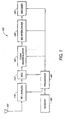
- Figure 1 shows a functional block diagram of a receiver 100 illustrative of what may be used in a CDMA wireless phone operating in a communication system that is compliant with the IS-95 or CDMA 2000 system standards.
- the receiver 100 may represent one half of a transceiver.
- a signal which may include a pilot signal, is modulated at a transmitter in accordance with specified signal standards and is then transmitted to the receiver 100.
- An antenna 102 at the front end of the receiver 100 interfaces the receiver 100 to the wireless communication link.
- the received signal at the output of the antenna 102 is coupled to a Radio Frequency (RF)/analog section 110.
- the RF/analog section 110 is typically used to tune the receiver 100 to a specific assigned frequency band, downconvert the received signal to a lower frequency signal, filter the signal, and amplify the signal.
- the output of the RF/analog section 110 is an analog signal that may be at a low Intermediate Frequency (IF) or at baseband.
- IF Intermediate Frequency
- the RF/analog section 110 may output an In-phase (I) signal as well as a Quadrature (Q) signal.
- the processed analog signal is then coupled to an Analog to Digital Converter (ADC) 112 where the signal is sampled and converted to a digital representation.
- ADC Analog to Digital Converter
- the digital representation of the received signal is then coupled to a CDMA demodulator 120 where direct sequence spreading is removed from the incoming signal.
- the CDMA demodulator may represent the functional block where pilot signal recovery may occur.
- the pilot signal is a bit stream of zeros that is spread with a zero Walsh code.
- the pilot signal chips are encoded with short pseudo noise (PN) sequences used to isolate one cell or sector from another. The offset enables reuse of the Walsh codes in every sector. Correlation with the PN sequence used to encode the pilot signal recovers the phase of the pilot signal.
- PN pseudo noise
- the resulting despread symbols are then coupled to a deinterleaver 130.
- the transmitted signal may be interleaved in order to lessen the effects of a burst of errors that may be caused, for example, by a fast signal fade due to destructively combining multipaths at the receiver front end. Interleaving the symbols before transmission and deinterleaving after reception causes bursts of errors to be spread out in time and to appear to the decoder as if they were random errors.
- the deinterleaver 130 performs block deinterleaving on the received symbols to rearrange the symbols to the order they were in prior to interleaving at the transmitter. The deinterleaved symbols are then coupled to the input of a decoder 140.
- the symbols are decoded in a manner consistent with the encoding process used in the transmitter.
- Different channels in the communication link may use different types of Forward Error Correction (FEC).
- FEC Forward Error Correction
- Some channels may use different types of FEC depending on the particular radio configuration.
- symbols may be convolutionally encoded or turbo encoded depending on the supported radio configuration.
- the receiver 100 may implement a convolutional decoder, such as a Viterbi decoder, as the decoder 140 when the symbols are convolutionally encoded and the receiver 100 may implement a turbo decoder as the decoder 140 when the symbols are turbo encoded.
- the decoded bits that are outputted from the decoder 140 may also include other signal quality indicators such as parity bits or Cyclic Redundancy Check (CRC) bits.
- CRC Cyclic Redundancy Check
- the output of the decoder 140 may be coupled to additional processing stages or may be coupled to a destination, such as a control register or user interface. The subsequent stages are not shown in Figure 1 for purposes of clarity.
- Each of the stages in the receiver 100 may be operationally coupled to a processor 180.
- the processor may interface with, and receive instructions from, memory 190.
- the processor may manage, assist, or perform some of the receiver tasks.
- the processor 180 may communicate the results from one of the functions to another of the functions in the receiver.
- a pilot signal filter may be used to limit the noise bandwidth of the received signal.
- a pilot signal filter that has a bandwidth that is much wider than the bandwidth of the pilot signal has a corresponding noise bandwidth that is not optimized.
- An excessive noise bandwidth on the pilot signal filter reduces the SNR of the received pilot signal. When the communication link is operating under low SNR conditions, the excess noise bandwidth may significantly reduce the ability of the receiver to recover the pilot signal.
- the pilot signal filter should not have a bandwidth that is significantly smaller than the bandwidth of the pilot signal because then portions of the pilot signal may be attenuated by the filter.
- a narrow bandwidth pilot signal filter may result in a loss of a portion of the pilot signal and slow reaction time to fast fading conditions.
- the pilot signal filter may be implemented in analog form prior to the ADC or may be implemented as a digital filter after the ADC.
- the pilot signal filter preferably does not require a great deal of computation, and preferably does not cause phase delay errors.
- One way to accomplish this is to use a single-pole Infinite Impulse Response (IIR) filter.
- IIR Infinite Impulse Response
- the resolved pilot signal may then be used to align the information in a channel signal.
- the pilot signal filter may take any form, and may for example be a one-pole or two-pole filter, IIR or Finite Impulse Response (FIR) filter if the pilot signal source is sampled and the system is digital.
- FIG. 2 shows a first technique of processing the received pilot signal in order to derive information about the pilot signal, so as to select appropriate parameters for a pilot signal filter.
- the received Channel signal is represented as including a pilot signal 202 and a noise signal 204.
- a first filter, H1 210, having a corresponding first transform function represents the response characteristics of a first bandwidth estimation filter.
- H1 210 is shown as a low-pass filter having a cutoff frequency 208 well below the highest frequency 206 of the pilot signal 202. It may be appreciated that another filter shape may also be used.
- the first filter 210 passes a corresponding first portion of the pilot signal as well as the associated noise that falls within the passband of the filter 210.
- a second filter, H2 220 having a corresponding second transfer function represents the response characteristics of a second bandwidth estimation filter.
- the transfer function of the second filter 220 is shown in Figure 2 as a bandpass filter, although some other filter shape may also be used.
- the passband of the first filter, H1 210 is shown to not overlap the passband of the second filter, H2 220.
- the passband of a particular filter may be taken as a frequency where the transfer function shows an attenuation of signals by a defined amount relative to a passband frequency.
- a typical filter passband is defined by a -3dB frequency, although the passband may also be defined in terms of a -6dB frequency, -10dB frequency or any other frequency corresponding to an attenuation level.
- the transfer functions of the first filter 210 and the second filter 220 show relatively flat passbands and identical passband amplitudes. It should be understood that a relatively flat passband is not necessary and that the first filter 210 and the second filter 220 need not have identical passband characteristics. That is, the first filter 210 may have more, less, or the same passband attenuation relative to the second filter 220. Additionally, the filters may, but may not necessarily, have symmetric transfer functions.
- a noise filter, N 230, having a corresponding transfer function is used as a noise estimation filter.
- Figure 2 shows the transfer function of the noise filter 230 to be a high pass filter although it will be appreciated that other filter shapes may also be used.
- the noise filter 230 may be implemented as a highpass filter, it will be understood that a noise bandwidth of the received signal may be limited by additional elements (not shown) such that the noise power passed by a highpass filter is limited and not unbounded.
- the transfer function of the noise filter 230 is preferably selected so as to be outside the bandwidth of the pilot signal 202.
- noise filter 230 is selected such that the signal passed by the noise filter 230 represents a signal from which an estimate may be made of the noise in each of the pilot bandwidth estimation filters.
- a noise estimate may also be derived from a bandpass filter, and may overlap insignificant portions of other signals including the pilot signal, or known signals which may be predictably removed to obtain a noise estimate.
- the received pilot signal is filtered by each of the first filter 210, second filter 220, and noise filter 230.
- a determination of a pilot signal component output from each of the pilot bandwidth estimation filters is made.
- a determination of the noise component is made from the output of the noise filter 230.
- the pilot signal component may readily be determined by well-known means, such as by evaluating the power per unit bandwidth. The same type of evaluation may be performed on the output from the noise filter N 230.
- the pilot bandwidth estimation filters and the noise filter are analog filters and the respective components are determined using a Received Signal Strength Indication (RSSI).
- RSSI may, for example, be determined using a diode detector.
- RSSI may be determined for the output of the first filter 210 to provide an estimate of the signal strength of the pilot signal and noise present within the bandwidth of the first filter 210.
- the RSSI for the output of the second filter 220 provides an estimate of the signal strength of the pilot signal and noise present within the bandwidth of the second filter 220.
- the RSSI for the output of the noise filter 230 provides an estimate of the signal strength of the noise present within the bandwidth of the noise filter 230.
- the respective signal or noise components may be determined digitally.
- the digital filters may be Finite Impulse Response (FIR), Infinite Impulse Response (IIR) or some other type of digital filters.
- FIR Finite Impulse Response
- IIR Infinite Impulse Response
- the filter order may be two or less in order to facilitate implementation in firmware. However, any filter order may be used if comparable design constraints are not present.
- RSSI may be determined digitally by determining the power in the signal passed by the filter.
- the signals from each of the filters may be I and Q signals in quadrature.
- the quadrature signals may be summed and squared and subsequently filtered to produce RSSI power estimates.
- a signal energy may be determined by squaring the amplitudes of the signal and accumulating the squared values over a predetermined period of time.
- the magnitude of the filtered signal may be determined by taking the absolute value of the filtered signal amplitudes and accumulating over a predetermined period of time.
- the same technique used for determining the RSSI of the pilot signal components is used for the determining the RSSI of the noise component.
- Using the same technique for the pilot signal components as well as for the noise components ensures that any statistical variations introduced into the RSSI value due to the RSSI technique will be the same for signal as well as noise.
- the determined magnitude of the first filtered pilot signal component may be compared to the magnitude of the second filtered pilot signal component.
- the determined magnitude of the noise signal may be subtracted from the magnitudes of the filtered signals before comparing them.
- One way to determine and compare magnitudes is to calculate values proportional to the power per unit bandwidth of the various signals. However, other methods of determining and comparing the signal magnitudes may also be employed to achieve the same effect of deducing the bandwidth of the received pilot signal 202.
- the RSSI from the noise filter 230 is scaled such that an estimate of the noise power in each of the first filter 210 and the second filter 220 is obtained.
- the bandwidth of the first filter 210 is twenty percent (20%) narrower than the bandwidth of the noise filter 230.
- the RSSI of the noise filter 230 output may be scaled by a factor of 1/(1.20) to obtain an estimate of the noise power in the first filter bandwidth.
- the RSSI of the noise filter 230 output may be scaled in a similar manner to align with the bandwidth of the second filter 220.
- RSSI(H2) represents the RSSI value determined from the output of the second filter, H2 220.
- RSSI(H1) represents the RSSI value determined from the output of the first filter, H1 210
- RSSI(N) represents the RSSI value determined from the output of the noise filter, N 230.
- RSSI(N) may represent a scaled noise power value.
- a higher G(f) value indicates a higher pilot signal bandwidth indicating a larger pilot filter bandwidth should be used.
- a smaller G(f) value indicates a narrower pilot signal bandwidth and a narrower pilot filter bandwidth may be used to improve performance by minimizing in-band noise power.
- the pilot filter bandwidth may be updated as each value of G(f) is calculated, or may be updated on another predetermined schedule.
- the pilot filter bandwidth may be updated on a frame basis.
- the pilot filter bandwidth may be updated every 20 mS. The received pilot signal bandwidth is thus estimated as the signal is received and the pilot filter bandwidth adjusted on the basis of the estimate.
- the pilot filter bandwidth changes at substantially a real time basis.
- the output of the function G(f) may be thresholded against a predetermined threshold constant such that a pilot filter bandwidth is varied depending on whether G(f) is above or below the threshold.
- a predetermined threshold constant such that a pilot filter bandwidth is varied depending on whether G(f) is above or below the threshold.
- the bandwidth of the pilot filter is varied continuously based on the value of G(f).
- the bandwidth of an analog filter may be adjusted by varying component values of the filter elements.
- a varactor may be used to vary capacitance values, and thus the filter bandwidth.
- a varactor control voltage may be varied in discrete steps or may be varied continuously.
- the bandwidth of a digital filter may be varied by varying the filter coefficients.
- the filter coefficients may be varied according to predetermined discrete values or the filter coefficients may be varied by incremental values, thus allowing for substantially continuous variations in filter bandwidth.
- the embodiment illustrated in Figure 2 is not limited to two pilot bandwidth estimation filters. Additional filters may be introduced to obtain a more detailed estimate of the received pilot signal power distribution as a function of frequency.
- a single G(f) function or multiple G(f) functions may be used. Multiple G(f) functions, each having independent thresholds may be implemented and a threshold comparison tree may be created to compare the various G(f) function values against their corresponding thresholds. The results of the comparisons may then be used to determine the desired pilot signal bandwidth.
- the pilot filter is implemented digitally as an IIR filter, the results of the various G(f) function values may be used to determine one or more IIR filter coefficients.
- FIG. 3 shows an example of a frequency spectrum 300 for an embodiment that is a variation of the embodiment described above in Figure 2.
- a first, bandwidth estimation filter H1 310 having a first transfer function, is implemented as a lowpass filter similar to that shown in Figure 2.
- a second bandwidth estimation filter H2 320 has a lowpass response reflected in Figure 3, rather than a bandpass response as shown in Figure 2. Because both the first bandwidth estimation filter H1 310 and the second bandwidth estimation filter H2 320 are lowpass filters, the bandwidth of H2 320 encompasses H1 310.
- the filters H1 310 and H2 320 may be selected to be substantially overlapping.
- a noise filter 330 is implemented outside the anticipated bandwidth of the received pilot signal 202 in order to provide an estimate of the received noise power.
- signals produced by different filters may also be used for deducing the shape of the pilot signal 202 in order to better select parameters for the pilot filter.
- signals produced by different filters may also be used for deducing the shape of the pilot signal 202 in order to better select parameters for the pilot filter.
- combinations of two low-pass, two band-pass, or high-pass and band-pass filters may be appropriate.
- the magnitude of the received pilot signal component output from each of the bandwidth estimation filters, H1 310 and H2 320 may be determined in a manner as described above in relation to Figure 2.
- the magnitudes for the pilot signal components may be improved by adjusting the magnitude estimates to compensate for the contribution of the noise signal 204, as presumed from the magnitude estimate from the noise filter 330.
- Comparison of the magnitudes of the pilot signal within H1 310 and H2 320, whether compensated for noise or not, may include subtracting the magnitude obtained from H1 from the magnitude from H2.
- G(f) may, as examples, represent a simple ratio of the magnitudes, the ratio of the magnitudes compensated for noise, or a more complex function of the magnitudes.
- a threshold or series of thresholds may be calculated or empirically determined, and parameters of the pilot signal filter may be dynamically varied on the basis of whether G(f) exceeds a particular threshold.
- G(f) may also represent a more complex comparison of the magnitudes of more than two subsignals.
- G(f) may represent the ratio of a slope from a second to third magnitude over a slope from a first to a second magnitude.
- a multiplicity of subsignal magnitudes may be compared in a variety of ways to arrive at a value of G(f).
- a variety of methods ranging from calculation to look-up table may be used to dynamically vary the parameters of the pilot signal filter in response to the value of G(f).
- G(f) may be derived from the combined results of two or more sequential measurements. The various magnitude values may be determined from sequential samples of the received pilot signal or from a single sample.
- FIG. 4 represents an example of the frequency spectrum of another embodiment.
- the embodiment shown in Figure 4 is similar to the embodiment shown in Figure 2.
- a plurality of substantially non-overlapping filters are used to estimate the bandwidth of a received pilot signal 202 in the presence of noise 204.
- the filters H1 ... H4 are correlators instead of filters.
- Each of the filters H1 410, H2 412, H3 414, H4 416, and N 420 are integrate and dump correlators.
- the integrate and dump correlators may be implemented using a Digital Signal Processor (DSP).
- DSP Digital Signal Processor
- the filters are generated by correlating the received pilot signal 202 and noise with a signal, such as a sinusoid, at the desired center frequency.
- the filters H1 410, H2 412, H3 414, H4 416 and N 420 are each obtained by correlating the received pilot signal 202 and noise 204 with a rotating exponential at the center frequency of H1, H2, H3, H4 and N, respectively.
- Other filtering techniques may also be employed to provide what may be viewed as a series of relatively narrow band-pass, or essentially as Fourier transforms of the signal evaluated at the frequencies of interest.
- the integrate and dump correlators may be high order sinc ((sin x)/x) FIR filters having narrow passbands.
- the correlation embodiment may also be used to evaluation only a couple of frequency bands as described in Figures 2.
- a frequency 460 may be determined at which the power of the pilot signal 202 is approximately equal to the noise signal power.
- the parameters of pilot signal filter may then be adjusted such that the cutoff frequency is set to about the determined frequency 460.
- the received signal may be represented by a series of samples P ot (n) at a sample frequency f s .
- Signals H1 410 through H4 416 and N 420 are correlations between the received signal and a rotating exponential at an appropriate radian frequency ⁇ .
- Eqn. 2 represents a Discrete Fourier Transform.
- the bandwidth of the correlators may be varied by adjusting the integation length L.
- the result is an integrate and dump correlator that is a FIR filter of order L.
- L is at least 2 and preferably 3 or more.
- the magnitudes of the pilot signal component within each filter may be determined after the correlation. Then, the resulting values may be provided to an appropriately defined G(f) function, such as those defined with respect to the embodiment of Figure 2. The output value of the G(f) function, may then be compared to a corresponding threshold to determine a pilot filter coefficient or to otherwise vary a pilot filter bandwidth.
- a frame may represent 20 mS of time in a system having a chip rate of 1.2288 Mcps. Thus, 24,576 chips are present in any one frame.
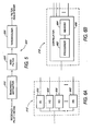
- FIG. 5 shows a functional block diagram of an embodiment of a pilot filter adjustment.
- a received pilot signal and accompanying noise are provided to a bandwidth estimator 510.
- the bandwidth estimator 510 determines the bandwidth of the received pilot signal.
- the output of the bandwidth estimator 510 may be a single signal or a plurality of signals.
- the output of the bandwidth estimator 510 is coupled to a RSSI filter 520, also referred to as a magnitude estimator.
- the RSSI filter, or magnitude estimator may determine the RSSI of a plurality of signals output from the bandwidth estimator 510, or may determine signal energy or magnitude of the signals.
- the output of the RSSI filter 520 is coupled to a thresholder 530, also referred to as a signal comparator.
- the thresholder 530 determines the value of at least one G(f) function and compares the value against a predetermined threshold. Based on the results of this comparison, a pilot filter bandwidth adjustment is made.
- the values of the corresponding G(f) functions may be used to vary the filter coefficients.
- the output of the thresholder 530 may represent the actual filter coefficients, a value that may be mapped to filter coefficients, a voltage, a current, or some other signal that is may be used to adjust a bandwidth of a pilot filter.
- Figure 6A shows a functional block diagram of a one embodiment of a bandwidth estimator 510.
- the bandwidth estimator 510 comprises a plurality of filters, H1 610 through HN 640.
- the frequency response of the filters may be substantially non-overlapping, as shown in Figure 2, or may be overlapping as shown in Figure 3.
- FIG. 6B shows a functional block diagram of an alternative embodiment of a bandwidth estimator 510.
- the bandwidth estimator 510 comprises a correlator 650 such as described in relation to Figure 4.
- the correlator 650 may, for example, comprise a processor 652 and memory 654 for generating the integrate and dump correlators.
- DSP digital signal processor
- ASIC application specific integrated circuit
- FPGA field programmable gate array
- a general purpose processor may be a microprocessor, but in the alternative, the processor may be any processor, controller, microcontroller, or state machine.
- a processor may also be implemented as a combination of computing devices, e.g., a combination of a DSP and a microprocessor, a plurality of microprocessors, one or more microprocessors in conjunction with a DSP core, or any other such configuration.
- a software module may reside in RAM memory, flash memory, ROM memory, EPROM memory, EEPROM memory, registers, hard disk, a removable disk, a CD-ROM, or any other form of storage medium known in the art.
- An exemplary storage medium is coupled to the processor such the processor can read information from, and write information to, the storage medium.
- the storage medium may be integral to the processor.
- the processor and the storage medium may reside in an ASIC.
- the ASIC may reside in a mobile station, base station, or base station controller.
- the processor and the storage medium may reside as discrete components.
Landscapes
- Engineering & Computer Science (AREA)
- Computer Networks & Wireless Communication (AREA)
- Signal Processing (AREA)
- Cable Transmission Systems, Equalization Of Radio And Reduction Of Echo (AREA)
- Noise Elimination (AREA)
Applications Claiming Priority (3)
| Application Number | Priority Date | Filing Date | Title |
|---|---|---|---|
| US36479502P | 2002-03-15 | 2002-03-15 | |
| US10/128,392 US6760362B2 (en) | 2002-03-15 | 2002-04-22 | Dynamic pilot filter bandwidth estimation |
| EP02807274A EP1488535B1 (fr) | 2002-03-15 | 2002-09-13 | Estimation de la largeur de bande d'un filtre pilote dynamique |
Related Parent Applications (2)
| Application Number | Title | Priority Date | Filing Date |
|---|---|---|---|
| EP02807274A Division EP1488535B1 (fr) | 2002-03-15 | 2002-09-13 | Estimation de la largeur de bande d'un filtre pilote dynamique |
| EP02807274.2 Division | 2002-09-13 |
Publications (2)
| Publication Number | Publication Date |
|---|---|
| EP1860785A2 true EP1860785A2 (fr) | 2007-11-28 |
| EP1860785A3 EP1860785A3 (fr) | 2010-03-31 |
Family
ID=38621949
Family Applications (1)
| Application Number | Title | Priority Date | Filing Date |
|---|---|---|---|
| EP07016348A Withdrawn EP1860785A3 (fr) | 2002-03-15 | 2002-09-13 | Estimation de la largeur de bande d'un filtre de pilote dynamique |
Country Status (1)
| Country | Link |
|---|---|
| EP (1) | EP1860785A3 (fr) |
Cited By (1)
| Publication number | Priority date | Publication date | Assignee | Title |
|---|---|---|---|---|
| WO2014112916A1 (fr) * | 2013-01-17 | 2014-07-24 | Telefonaktiebolaget L M Ericsson (Publ) | Détermination de la bande passante de transmission de signal |
Citations (2)
| Publication number | Priority date | Publication date | Assignee | Title |
|---|---|---|---|---|
| EP0898379A2 (fr) | 1997-08-20 | 1999-02-24 | Matsushita Electric Industrial Co., Ltd. | Communication à accès multiple par division de codes avec détection assistée par pilote |
| EP0901239A2 (fr) | 1997-09-02 | 1999-03-10 | Nec Corporation | Système faisant la moyenne des niveaux de réception d'un signal pilote |
-
2002
- 2002-09-13 EP EP07016348A patent/EP1860785A3/fr not_active Withdrawn
Patent Citations (2)
| Publication number | Priority date | Publication date | Assignee | Title |
|---|---|---|---|---|
| EP0898379A2 (fr) | 1997-08-20 | 1999-02-24 | Matsushita Electric Industrial Co., Ltd. | Communication à accès multiple par division de codes avec détection assistée par pilote |
| EP0901239A2 (fr) | 1997-09-02 | 1999-03-10 | Nec Corporation | Système faisant la moyenne des niveaux de réception d'un signal pilote |
Cited By (2)
| Publication number | Priority date | Publication date | Assignee | Title |
|---|---|---|---|---|
| WO2014112916A1 (fr) * | 2013-01-17 | 2014-07-24 | Telefonaktiebolaget L M Ericsson (Publ) | Détermination de la bande passante de transmission de signal |
| US9722744B2 (en) | 2013-01-17 | 2017-08-01 | Telefonaktiebolaget Lm Ericsson (Publ) | Determining signal transmission bandwidth |
Also Published As
| Publication number | Publication date |
|---|---|
| EP1860785A3 (fr) | 2010-03-31 |
Similar Documents
| Publication | Publication Date | Title |
|---|---|---|
| EP1488535B1 (fr) | Estimation de la largeur de bande d'un filtre pilote dynamique | |
| US6680967B1 (en) | Receiver | |
| US7433388B2 (en) | Receiver noise estimation | |
| US6901243B2 (en) | Method and apparatus for mitigating adjacent channel interference in a wireless communication system | |
| US6493329B1 (en) | Adaptive channel estimation in a wireless communication system | |
| US6452917B1 (en) | Channel estimation in a CDMA wireless communication system | |
| US6956895B2 (en) | Method and arrangement for reducing frequency offset in a radio receiver | |
| EP0925652B1 (fr) | Demodulation coherente avec estimation de canal a commande decisionnelle pour communication numerique | |
| JP3700728B2 (ja) | 通信システムにおけるパワー推定方法および装置 | |
| JP3443113B2 (ja) | 無線受信装置及び無線受信方法 | |
| EP1243081B1 (fr) | Determination du facteur d'etalement | |
| AU739474B2 (en) | Device and method for measuring non-orthogonal noise power for CDMA communication system | |
| US7136428B2 (en) | Systems and techniques for measuring the performance of a communications system | |
| US6295311B1 (en) | Method and apparatus for compensating for phase differences in received signals | |
| EP1612947B1 (fr) | Procédé de changement adaptatif du signal d'entrée d'un décodeur de canal | |
| EP1513270B1 (fr) | Procédé d'estimation de l'étalement Doppler dans des systèmes de télécommunications radiomobile | |
| EP1860785A2 (fr) | Estimation de la largeur de bande d'un filtre de pilote dynamique | |
| Mjögeman et al. | Performance simulations of the UMTS common packet channel |
Legal Events
| Date | Code | Title | Description |
|---|---|---|---|
| PUAI | Public reference made under article 153(3) epc to a published international application that has entered the european phase |
Free format text: ORIGINAL CODE: 0009012 |
|
| 17P | Request for examination filed |
Effective date: 20070821 |
|
| AC | Divisional application: reference to earlier application |
Ref document number: 1488535 Country of ref document: EP Kind code of ref document: P |
|
| AK | Designated contracting states |
Kind code of ref document: A2 Designated state(s): AT BE BG CH CY CZ DE DK EE ES FI FR GB GR IE IT LI LU MC NL PT SE SK TR |
|
| PUAL | Search report despatched |
Free format text: ORIGINAL CODE: 0009013 |
|
| AK | Designated contracting states |
Kind code of ref document: A3 Designated state(s): AT BE BG CH CY CZ DE DK EE ES FI FR GB GR IE IT LI LU MC NL PT SE SK TR |
|
| 17Q | First examination report despatched |
Effective date: 20101102 |
|
| AKX | Designation fees paid |
Designated state(s): AT BE BG CH CY CZ DE DK EE ES FI FR GB GR IE IT LI LU MC NL PT SE SK TR |
|
| GRAP | Despatch of communication of intention to grant a patent |
Free format text: ORIGINAL CODE: EPIDOSNIGR1 |
|
| RIC1 | Information provided on ipc code assigned before grant |
Ipc: H04B 1/707 20110101AFI20110629BHEP |
|
| STAA | Information on the status of an ep patent application or granted ep patent |
Free format text: STATUS: THE APPLICATION IS DEEMED TO BE WITHDRAWN |
|
| 18D | Application deemed to be withdrawn |
Effective date: 20111209 |