EP1860492B1 - Method of spatial filtering and image capture device - Google Patents
Method of spatial filtering and image capture device Download PDFInfo
- Publication number
- EP1860492B1 EP1860492B1 EP06010768A EP06010768A EP1860492B1 EP 1860492 B1 EP1860492 B1 EP 1860492B1 EP 06010768 A EP06010768 A EP 06010768A EP 06010768 A EP06010768 A EP 06010768A EP 1860492 B1 EP1860492 B1 EP 1860492B1
- Authority
- EP
- European Patent Office
- Prior art keywords
- image
- sensor
- image sensor
- pixel
- relative movement
- Prior art date
- Legal status (The legal status is an assumption and is not a legal conclusion. Google has not performed a legal analysis and makes no representation as to the accuracy of the status listed.)
- Not-in-force
Links
- 238000001914 filtration Methods 0.000 title claims abstract description 22
- 238000000034 method Methods 0.000 title claims abstract description 16
- 230000033001 locomotion Effects 0.000 claims abstract description 55
- 230000003287 optical effect Effects 0.000 claims abstract description 27
- 230000001360 synchronised effect Effects 0.000 claims abstract 2
- 230000001419 dependent effect Effects 0.000 claims description 10
- 230000005693 optoelectronics Effects 0.000 claims description 8
- 238000006073 displacement reaction Methods 0.000 claims description 6
- 238000004519 manufacturing process Methods 0.000 claims description 4
- 238000003860 storage Methods 0.000 claims description 2
- 206010034960 Photophobia Diseases 0.000 claims 2
- 208000013469 light sensitivity Diseases 0.000 claims 2
- 238000003384 imaging method Methods 0.000 abstract 2
- 206010034972 Photosensitivity reaction Diseases 0.000 description 25
- 230000036211 photosensitivity Effects 0.000 description 25
- 230000003595 spectral effect Effects 0.000 description 7
- 230000035945 sensitivity Effects 0.000 description 6
- 230000001629 suppression Effects 0.000 description 6
- 238000010586 diagram Methods 0.000 description 4
- 230000000694 effects Effects 0.000 description 4
- 238000011045 prefiltration Methods 0.000 description 3
- 230000007423 decrease Effects 0.000 description 2
- 238000009826 distribution Methods 0.000 description 2
- 230000036961 partial effect Effects 0.000 description 2
- 230000000284 resting effect Effects 0.000 description 2
- 238000005070 sampling Methods 0.000 description 2
- 230000006641 stabilisation Effects 0.000 description 2
- 238000011105 stabilization Methods 0.000 description 2
- 230000003068 static effect Effects 0.000 description 2
- 230000002238 attenuated effect Effects 0.000 description 1
- 239000003086 colorant Substances 0.000 description 1
- 239000013078 crystal Substances 0.000 description 1
- 230000003247 decreasing effect Effects 0.000 description 1
- 238000009792 diffusion process Methods 0.000 description 1
- 230000002996 emotional effect Effects 0.000 description 1
- 238000009472 formulation Methods 0.000 description 1
- 238000002955 isolation Methods 0.000 description 1
- 239000000203 mixture Substances 0.000 description 1
- 230000002829 reductive effect Effects 0.000 description 1
- 230000008672 reprogramming Effects 0.000 description 1
- 239000003381 stabilizer Substances 0.000 description 1
- 238000011144 upstream manufacturing Methods 0.000 description 1
- 238000001429 visible spectrum Methods 0.000 description 1
Images


Classifications
-
- G—PHYSICS
- G03—PHOTOGRAPHY; CINEMATOGRAPHY; ANALOGOUS TECHNIQUES USING WAVES OTHER THAN OPTICAL WAVES; ELECTROGRAPHY; HOLOGRAPHY
- G03B—APPARATUS OR ARRANGEMENTS FOR TAKING PHOTOGRAPHS OR FOR PROJECTING OR VIEWING THEM; APPARATUS OR ARRANGEMENTS EMPLOYING ANALOGOUS TECHNIQUES USING WAVES OTHER THAN OPTICAL WAVES; ACCESSORIES THEREFOR
- G03B5/00—Adjustment of optical system relative to image or object surface other than for focusing
-
- H—ELECTRICITY
- H04—ELECTRIC COMMUNICATION TECHNIQUE
- H04N—PICTORIAL COMMUNICATION, e.g. TELEVISION
- H04N23/00—Cameras or camera modules comprising electronic image sensors; Control thereof
- H04N23/58—Means for changing the camera field of view without moving the camera body, e.g. nutating or panning of optics or image sensors
-
- H—ELECTRICITY
- H04—ELECTRIC COMMUNICATION TECHNIQUE
- H04N—PICTORIAL COMMUNICATION, e.g. TELEVISION
- H04N23/00—Cameras or camera modules comprising electronic image sensors; Control thereof
- H04N23/50—Constructional details
- H04N23/55—Optical parts specially adapted for electronic image sensors; Mounting thereof
-
- H—ELECTRICITY
- H04—ELECTRIC COMMUNICATION TECHNIQUE
- H04N—PICTORIAL COMMUNICATION, e.g. TELEVISION
- H04N25/00—Circuitry of solid-state image sensors [SSIS]; Control thereof
- H04N25/48—Increasing resolution by shifting the sensor relative to the scene
-
- G—PHYSICS
- G03—PHOTOGRAPHY; CINEMATOGRAPHY; ANALOGOUS TECHNIQUES USING WAVES OTHER THAN OPTICAL WAVES; ELECTROGRAPHY; HOLOGRAPHY
- G03B—APPARATUS OR ARRANGEMENTS FOR TAKING PHOTOGRAPHS OR FOR PROJECTING OR VIEWING THEM; APPARATUS OR ARRANGEMENTS EMPLOYING ANALOGOUS TECHNIQUES USING WAVES OTHER THAN OPTICAL WAVES; ACCESSORIES THEREFOR
- G03B2205/00—Adjustment of optical system relative to image or object surface other than for focusing
- G03B2205/0007—Movement of one or more optical elements for control of motion blur
- G03B2205/0038—Movement of one or more optical elements for control of motion blur by displacing the image plane with respect to the optical axis
Definitions
- the invention relates to a method for spatial frequency filtering and an image recording apparatus according to the preambles of the independent claims.
- cameras with optoelectronic image sensors that have a regular pixel arrangement are equipped with optical prefiltering or spatial frequency filtering.
- the optical pre-filtering is in principle required for image sensors, if aliasing effects are to be avoided.
- the so-called alias structures can also not subsequently be removed, for example, by means of digital filtering of the pixel data, since the digital data do not allow a distinction between alias structures and image scene structures.
- the theoretical background is known in the context of the Nyquist-Shannon sampling theorem.
- the Nyquist frequency is defined by half the sampling frequency.
- optical prefiltering or spatial frequency filtering should therefore suppress as completely as possible all structures of the image of the scene to be recorded projected onto the image sensor by the objective, which are finer than half the distance between two neighboring pixels of the same spectral photosensitivity, and should not suppress all coarser structures as far as possible. Since this is technically impossible, there must always be a compromise between the suppression of alias artifacts and the highest possible image sharpness.
- the photosensitivity of a theoretical, ideal pixel of an image sensor should decrease with increasing distance from its center, but also the locations of neighboring pixels are also detected.
- the corresponding direction-dependent curve depends both on the location-dependent profile of the photosensitivity of a real sensor pixel and on the geometric arrangement of the sensor pixels relative to each other and also on the desired compromise between high image sharpness and high suppression of alias artifacts.
- An ideal optical pre-filter should distribute the light of the image onto a real sensor pixel so that it has the photosensitivity profile of the idealized pixel as far as possible.
- each optical prefilter is to use image sensors with a resolution greater than the desired resolution (result).
- the filter performance increases with the ratio between the fineness or frequency of the pixel grid and the result grid.
- this solution leads to a lower photosensitivity, as with sensors with more pixels, the effective photosensitive area of the sensor decreases due to the necessary supply lines on the sensor, since the latter require a consistently large area per pixel.
- this solution leads to an increased data processing demand and, consequently, to the need to use a more powerful electronics with increased energy requirements.
- the image recording device has corresponding means for performing the steps described.
- a method of spatial frequency filtering is proposed in an image pickup apparatus having an objective which projects a captured image onto one or more photosensitive pixel opto-electronic image sensors. At least one optoelectronic image sensor and the image projected onto it by the objective are moved relative to one another during image acquisition in the pixel plane, in particular controllably.
- This can be realized in practice by a movement of the image sensor with a fixed image, or a movement of the image with a fixed image sensor, or by a combination of both movements.
- the motion vector of the relative movement takes pre-definable locations with a each predeterminable length of stay or speed. The motion vector thus describes a closed trajectory or trajectory, which can be used to characterize the movement.
- Each pixel of the sensor moves relative to the image or the image moves relative to the sensor, so that a sensor pixel detects a larger area of the image than would be the case without relative movement.
- the locations of the motion vector at a lower speed or longer residence time correspond to locations of increased exposure time and thus also increased relative photosensitivity of a sensor pixel relative to the corresponding image location.
- any desired course of the location-dependent photosensitivity of a sensor pixel relative to the image can be achieved.
- Another particular advantage of the invention lies in the variable configurability of the trajectory.
- an optical pre-filtering can be achieved, which is adaptable to various image recording situations and operating modes of the camera, as described below.
- the relative movement between the sensor and the image can be measured in a variety of ways, e.g. be effected by means of electromagnetic or piezoelectric effect driving elements.
- an image sensor or an optical element can be moved at low production costs on any trajectories with variable speed.
- the relative movement between the sensor and the image when a movement path or movement of a sensor or pixel is mentioned.
- This relative movement may also be effected by movement of an optical element preceding the sensor, unless expressly excluded.
- image stabilization devices equipped with digital cameras or film cameras.
- Such an image stabilization device is, for example, in the JP 2004 271 694 A shown.
- the sensor upstream optical elements, for.
- lenses, lens groups or prisms mechanically adjustable, in particular laterally movable and / or pivotable, so that dithering or pivoting movements of a user of the camera can be compensated. That is, a conventional image stabilizer causes a frame captured by a sensor to remain constant.
- suitable reprogramming it is possible to effect by means of such a device, a relative movement of the detected image with respect to the sensor.
- the invention can be used with all types of digital image sensors. Since the trajectories of a prefiltering according to the invention are necessarily always the same for all pixels of a sensor, in the case of sensors with pixels of different spectral photosensitivity, preferably each pixel type should have the same static, location-related, relative photosensitivity and the same geometric arrangement on the sensor surface and thus also the same number of pixels ,
- a trajectory should be designed, inter alia, as a function of the desired location-dependent photosensitivity profile of a pixel relative to the image, of the geometric arrangement of the neighboring pixels of equal spectral sensitivity and of the pixel form and of any light collecting lenses above the pixels. If, for example, the distance of a pixel to its neighboring pixels of the same spectral sensitivity in the horizontal direction is greater than in the vertical direction, the course of the trajectories should take this asymmetry into account.
- the advantage of an arbitrarily configurable trajectory is, in particular, that for each image sensor type with its specific pixel arrangements and parameters, any desired optical filter curve course can be optimally achieved.
- a trajectory there are many different variants for a trajectory conceivable. So it is sufficient in many cases, e.g. already starting to use a resulting from the superposition of simple circular motions of different frequencies and amplitudes trajectory to approximately achieve a desired location-specific photosensitivity course (see examples below). From the context of the location and duration of such a technically realized trajectory and the physical and geometric properties of a pixel, a location-dependent relative photosensitivity profile for a pixel can be derived so that the quality of the approach is assessed by comparison with the desired photosensitivity profile can.
- a postfiltering adapted to the prefiltering is carried out digitally. This is an advantage since each site is different Photosensitive profile in a specific way leads to desirable and unwanted structures to be recorded in the sensor image signal. Only when the image processing electronics, the subsequent digital filtering is tuned in their characteristics specifically to the respective active optical prefilter characteristic, an optimal result image can be achieved.
- the characteristic required for the respective digital postfiltering can be calculated from the respective location-specific photosensitivity profile of the optical prefiltering.
- At least two non-identical intermediate images are recorded and processed into a result image.
- the intermediate images are recorded, for example, by an image sensor in succession, which is preferably shifted by one pixel line between the images.
- the intermediate images can also be recorded by at least two image sensors.
- full-color images in particular with a Bayer sensor or a FOVEON X3 image sensor
- black-and-white images or partial color images can be recorded.
- a black-and-white intermediate image is picked up or generated by an image sensor and a red / blue interim image by another image sensor.
- an image recording apparatus according to claim 7 is also presented.
- the image recording device comprises means for carrying out embodiments of the method according to the invention.
- the image recording device has storage means for storing data of at least one trajectory or movement path of the image sensor or optical element.
- the trajectories and thus the location-related course of the photosensitivity of a pixel relative to the image are controllable, so that different location-related photosensitivity profiles can be achieved, the parameters required for this, in particular from the camera manufacturer, can be stored and retrieved by the user.
- three different trajectories are available.
- a pixel covers only part of the rest region of neighboring pixels of the same spectral sensitivity during the movement, so that a high image sharpness is obtained but only a small alias artifact suppression.
- a pixel In another movement path provided for normal recordings, a pixel covers, for example, a large part of the rest areas of the next neighboring pixels during the movement. This trajectory provides a compromise between image sharpness and alias artifact suppression suitable for most image scenes. In the case of a third trajectory, for example, a pixel covers all resting areas of the next and sometimes also of the more distant neighboring pixels during the movement. This trajectory allows a desired sharpening reduction for Portrait shots with the best alias artifact suppression. It is understood that further finer graded filter characteristics can be provided. It is further proposed that each stored trajectory is combined with an associated digital post-filter function. Image pickup devices with conventional optical filters have not yet had this type of variable filtering.
- trajectories or trajectories can be executed and stored.
- Operating modes for detecting an increased brightness range or increased image sharpness can be provided.
- the pixels of the sensors offset by a certain pixel pitch in a certain direction against each other to produce in known manner from the different data of the sensor images, a result image of higher image sharpness.
- trajectories are preferably used as if the camera had only a single sensor with a correspondingly higher number of pixels or pixel density, resulting in trajectories with a lower amplitude and different shape. Since the trajectories of the sensors are the same here, a single optical element for displacing the image on the sensors can be moved instead of the sensors.
- a constant displacement vector can be stored and recalled by means of which an undesired, production-related mechanical offset between the pixels of two or more sensors can be compensated, so that in the production only an exactly parallel alignment of the pixel rows or pixel columns of the sensors must be made.
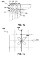
- FIG. 1a schematically a section of a first image sensor 100 is shown.
- the image sensor 100 has pixels I of the same spectral sensitivity, which are arranged in a square grid.
- the sensor 100 has sensor lines 110, 120, 130, etc., and sensor columns 101, 102, 103, and so on.
- similar pixels 111, 112, 113, etc. in the sensor row 120, similar pixels 121, 122, 123, etc. are juxtaposed.
- leads and other electronic components that are not shown in the schematic view lie between the individual pixels.
- Such sensors for use with an embodiment of the present invention are preferably provided with pixels which can simultaneously register all colors or only a same portion of the visible spectrum.
- FIG. 2a schematically a section of a second image sensor 200 is shown.
- the image sensor 200 has pixels R and B of different spectral sensitivity arranged in a square grid.
- the sensor 200 has, for example, red pixels R and blue pixels B, which are arranged alternately in sensor lines 210, 220, 230 etc. and sensor columns 201, 202, 203, etc.
- red pixels 211, 213, etc., and blue pixels 212, 214, etc. are alternately juxtaposed in the sensor row 220, alternately blue pixels 221, 223, etc., and red pixels 222, 224, and so on.
- the described second sensor 200 may be used together with an image sensor 100 with black-and-white or green pixels according to FIG FIG. 1a eg in a two-sensor camera accordingly FIG. 3 can be used, in which in known manner from the image data 71, 72 of the two sensors 41, 42, a single result image 78 is determined.
- FIG. 1b is an example of a trajectory 1003 for a sensor according to FIG. 1a shown in a diagram 1000.
- the diagram 1000 has an x-axis 1001 and a ⁇ -axis 1002, which span a plane. It is the sensor level.
- the origin of the coordinate system ie the Intersection of the axes 1001 and 1002, the rest position of the sensor center is assigned. Since all the individual pixels of an image sensor move identically with the sensor center, the origin can also be assigned to the center of a single pixel.
- the centers of adjacent single pixels are spaced according to the coordinates on the axes 1001 and 1002. For example, if pixel 122 is at the origin (0/0) of the coordinate system, pixel 123 is at position (1/0), pixel 112 at position (0/1), and so on.
- the illustrated trajectory is approximately cross-shaped, with the major axes of the cross rotated 45 ° to the coordinate axes.
- the four arms are approximately drop-shaped, wherein the shape approximately corresponds to a superposition of four circles whose centers are equally spaced on the coordinate axes corresponds. It should be noted that, for example, with a helical trajectory or with Trajectories of any suitable form, the teaching of the invention can be realized.
- a sensor pixel captures a significantly larger area of the image compared to the size of its photosensitive area and thus also extends to resting locations of neighboring pixels, with the resulting photosensitivity decreasing from the center of rest and having the desired directional dependence derived from the geometry of the pixel array ,
- FIG. 1b an example of a trajectory 2003 for a sensor according to FIG. 2a with two different color sensitive (R, B) pixel types shown in a diagram 2000.
- the diagram 2000 also has an x-axis 2001 and a y-axis 2002 spanning a plane.
- the origin of the coordinate system is in turn assigned to the rest position of the sensor or pixel center. For example, when the R pixel 222 is at the origin (0/0) of the coordinate system, the B pixel 223 is located at the position (1/0) but the nearest R pixels are farther away at the positions 211, 213, 231 and 233 lie.
- the trajectory 2003 according to FIG. 2b is similar to the trajectory 1003 according to FIG. 1b , with some differences.
- the arms of the cross are aligned parallel to the coordinate axes 2001, 2002.
- the shape of the trajectory is approximated by a superposition of four circles whose centers lie on diagonals of the coordinate system and whose radii are larger than the corresponding radii FIG. 1b are.
- trajectories of quite a different kind can be used to achieve the desired photosensitivity profile.
- the superimposition of two circular motions was chosen here because it is technically particularly easy to implement and since it already allows a good approximation to the desired result here. It is understood, however, that the trajectories may also be described by completely different functions, and the embodiments described herein are to be understood as illustrative and not restrictive.
- FIG. 3 is an embodiment of a digital camera referred to, which has an example of an optical prefiltering according to the invention and designated overall by 3.
- the image captured by a lens 10 is projected onto two image sensors 41 and 42 via a rotating mirror sector gear 31.
- the image sensor 41 is a black and white or green image sensor according to FIG. 1a and the image sensor 42 as a red-blue sensor according to FIG. 2a educated.
- the image sensor 41 is detected by a motor 51 during exposure on a trajectory according to FIG. 1b , the image sensor 42 from a motor 52 on a trajectory according to FIG. 2b emotional.
- the respective movement plane is perpendicular to the drawing plane.
- the rapidly rotating mirror sector wheel 31 is formed with reflective and transmissive sectors, so that the captured image as possible during the exposure time is repeatedly projected alternately on the image sensor 41 and 42, whereby a quasi-simultaneous exposure of both sensors takes place.
- each image sensor will always receive the light from at least exactly one complete cycle of its respective trajectory.
- the light flow to a sensor during such a cycle is interrupted or attenuated once or several times during the exposure time by a sector wheel segment.
- an even number of complete trajectories or trajectories with an arbitrary starting point is always carried out during an exposure time of a pixel.
- mirror sectors and gap sectors preferably have equal angular widths and, preferably, the angle of rotation of the sector wheel is always an odd multiple of a mirror sector angle plus gap sector angle. For cameras with two rotating mirror sector wheels for splitting the image into 3 images, similar conditions apply.
- optical Element 56 can be used for relative movement between image and sensor.
- a separate optical element with its own drive can also be provided in front of each sensor. The latter would allow, as in the case of separate sensor drives, also an optional static offset between the sensor pixels of the two sensors. Such an offset can then be used in a known manner to increase the sharpness of the resulting image 78, as already described above. Due to the motor-driven drives this offset can be withdrawn at any time again, for example, in a known manner to achieve a result image, which can represent a high brightness range.
- FIG. 3 further comprises a camera control means 60 provided for controlling the image sensors 41 and 42, the motors 51, 52 and 55, the image processing means 75 and other means.
Landscapes
- Engineering & Computer Science (AREA)
- Multimedia (AREA)
- Signal Processing (AREA)
- Physics & Mathematics (AREA)
- General Physics & Mathematics (AREA)
- Studio Devices (AREA)
- Holo Graphy (AREA)
- Liquid Crystal (AREA)
- Facsimile Image Signal Circuits (AREA)
- Shutters For Cameras (AREA)
- Blocking Light For Cameras (AREA)
- Transforming Light Signals Into Electric Signals (AREA)
Abstract
Description
Die Erfindung betrifft ein Verfahren zur Ortsfrequenzfilterung sowie ein Bildaufnahmegerät nach den Oberbegriffen der unabhängigen Patentansprüche.The invention relates to a method for spatial frequency filtering and an image recording apparatus according to the preambles of the independent claims.
Im folgenden wird im wesentlichen auf Filmkameras Bezug genommen, ohne dass die Erfindung darauf beschränkt wäre. Es versteht sich, dass das erfindungsgemäße Verfahren z. B. ebenso für Fotokameras oder andere Bildaufnahmegeräte anwendbar ist.In the following, reference is essentially made to film cameras, without the invention being restricted thereto. It is understood that the inventive method z. B. is also applicable for photo cameras or other image recording devices.
Um ein möglichst naturgetreues und artefaktfreies Bild aufnehmen zu können, sind Kameras mit optoelektronischen Bildsensoren, die eine regelmäßige Pixelanordnung aufweisen, mit einer optischen Vorfilterung bzw. Ortsfrequenzfilterung ausgestattet. Die optische Vorfilterung ist bei Bildsensoren prinzipiell erforderlich, wenn Alias-Effekte vermieden werden sollen. Die sog. Alias-Strukturen können auch nicht nachträglich bspw. mittels digitaler Filterung der Pixeldaten entfernt werden, da die digitalen Daten keine Unterscheidung zwischen Alias-Strukturen und Bildszenen-Strukturen zulassen.In order to be able to record a picture that is as lifelike and free of artifacts as possible, cameras with optoelectronic image sensors that have a regular pixel arrangement are equipped with optical prefiltering or spatial frequency filtering. The optical pre-filtering is in principle required for image sensors, if aliasing effects are to be avoided. The so-called alias structures can also not subsequently be removed, for example, by means of digital filtering of the pixel data, since the digital data do not allow a distinction between alias structures and image scene structures.
Der theoretische Hintergrund ist im Zusammenhang mit dem Nyquist-Shannon-Abtasttheorem bekannt. Die Nyquist-Frequenz wird durch die halbe Abtastfrequenz definiert.The theoretical background is known in the context of the Nyquist-Shannon sampling theorem. The Nyquist frequency is defined by half the sampling frequency.
Die optische Vorfilterung bzw. Ortsfrequenzfilterung sollte daher alle Strukturen des auf den Bildsensor vom Objektiv projizierten Abbilds der aufzunehmenden Szene, welche feiner als der halbe Abstand zwischen zwei benachbarten Pixeln gleicher spektraler Lichtempfindlichkeit sind, möglichst vollständig unterdrücken und alle gröberen Strukturen möglichst nicht unterdrücken. Da dies technisch unmöglich ist, muss immer ein Kompromiss zwischen der Unterdrückung von Alias-Artefakten und einer möglichst hohen Bildschärfe eingegangen werden.The optical prefiltering or spatial frequency filtering should therefore suppress as completely as possible all structures of the image of the scene to be recorded projected onto the image sensor by the objective, which are finer than half the distance between two neighboring pixels of the same spectral photosensitivity, and should not suppress all coarser structures as far as possible. Since this is technically impossible, there must always be a compromise between the suppression of alias artifacts and the highest possible image sharpness.
Die Lichtempfindlichkeit eines theoretischen, idealen Pixels eines Bildsensors sollte mit zunehmendem Abstand vom seinem Mittelpunkt aus abnehmen, wobei aber auch noch die Orte von Nachbarpixeln mit erfasst werden. Die entsprechende richtungsabhängige Kurve hängt sowohl vom ortsabhängigen Verlauf der Lichtempfindlichkeit eines realen Sensorpixels als auch von der geometrischen Anordnung der Sensorpixel zueinander und auch von dem gewünschten Kompromiss zwischen hoher Bildschärfe und hoher Unterdrückung von Aliasartefakten ab. Ein ideales optisches Vorfilter sollte das Licht des Abbilds so auf ein reales Sensorpixel verteilen, dass dieses den Lichtempfindlichkeitsverlauf des idealisierten Pixels soweit als möglich aufweist.The photosensitivity of a theoretical, ideal pixel of an image sensor should decrease with increasing distance from its center, but also the locations of neighboring pixels are also detected. The corresponding direction-dependent curve depends both on the location-dependent profile of the photosensitivity of a real sensor pixel and on the geometric arrangement of the sensor pixels relative to each other and also on the desired compromise between high image sharpness and high suppression of alias artifacts. An ideal optical pre-filter should distribute the light of the image onto a real sensor pixel so that it has the photosensitivity profile of the idealized pixel as far as possible.
Im Stand der Technik existieren hierzu unterschiedliche Lösungen. Es gibt digitale Bildaufnahmegeräte, bei denen allein durch die Unschärfe des Objektivs der Lichtempfindlichkeitsverlauf der Sensorpixel relativ zum Abbild verändert wird. Da hiermit in keinem Fall der gewünschte Verlauf erzielt werden kann, werden in der Regel jedoch speziell für diesen Zweck ausgestaltete optische Filter verwendet. So werden vor den Sensorpixeln angeordnete Zerstreuungsscheiben, welche die auftreffenden Lichtstrahlen in alle Richtungen verbreitern, so dass ein Pixel einen größeren Bereich des Abbilds registriert, verwendet. Hiermit kann jedoch nicht die erforderliche Richtungsabhängigkeit der Filterung erreicht werden. Daher werden vor allem Filter verwendet, die auf dem Prinzip der Doppelbrechung in Kristallen basieren. Ein eintreffender Strahl wird durch den Filter in bspw. zwei oder vier ausgehende Strahlen aufgeteilt, womit eine richtungsabhängige Filterung erreicht wird, welche für übliche Pixelanordnungen bereits bessere Ergebnisse liefert. Ein derartiges Verfahren ist in der
In der
Die
The
Mit diesen Verfahren kann jedoch kein gewünschter ortsabhängiger Filterverlauf erreicht werden.With these methods, however, no desired location-dependent filter profile can be achieved.
Eine Möglichkeit, die Wirksamkeit einer jeden optischen Vorfilterung zu erhöhen, besteht darin, Bildsensoren mit einer größeren als der erwünschten Auflösung (Ergebnis) zu verwenden. Die Filterleistung steigt mit dem Verhältnis zwischen der Feinheit bzw. Frequenz des Pixelrasters und des Ergebnisrasters. Diese Lösung führt allerdings zu einer geringeren Lichtempfindlichkeit, da bei Sensoren mit mehr Pixeln die effektive lichtempfindliche Fläche des Sensors aufgrund der notwendigen Zuleitungen auf dem Sensor abnimmt, da letztere eine gleichbleibend große Fläche je Pixel benötigen. Weiterhin führt diese Lösung zu einem erhöhten Datenverarbeitungsbedarf und damit einhergehend zu der Notwendigkeit, eine leistungsfähigere Elektronik mit erhöhtem Energiebedarf zu verwenden.One way to increase the effectiveness of each optical prefilter is to use image sensors with a resolution greater than the desired resolution (result). The filter performance increases with the ratio between the fineness or frequency of the pixel grid and the result grid. However, this solution leads to a lower photosensitivity, as with sensors with more pixels, the effective photosensitive area of the sensor decreases due to the necessary supply lines on the sensor, since the latter require a consistently large area per pixel. Furthermore, this solution leads to an increased data processing demand and, consequently, to the need to use a more powerful electronics with increased energy requirements.
Ein weiterer Nachteil bekannter optischer Vorfilterungen besteht darin, dass der Verlauf bzw. die Ausgestaltung der Filterkurve fest vorgegeben und nicht variabel ist. Es wäre hingegen vorteilhaft, die Ausgestaltung der Filterung an die Situation anpassen zu können. Beispielsweise erfordern Portraitaufnahmen eine starke Unterdrückung von Aliasingartefakten bei geringerer Anforderung an die Schärfe, wohingegen bei Aufnahmen von Totalen mit vielen feinen Details und wenig regelmäßigen Strukturen, wie Landschaftsaufnahmen, meist nur wenig Aliasingartefakte auftreten und eine möglichst hohe Schärfe im Vordergrund steht.Another disadvantage of known optical pre-filtering is that the course or the design of the filter curve is fixed and not variable. On the other hand, it would be advantageous to be able to adapt the design of the filtering to the situation. For example, portrait shots require strong suppression of aliasing artifacts with less sharpness requirement, whereas when shooting shots with many fine details and less regular structures such as landscape shots, there is usually little aliasing artifacts and as much sharpness as possible.
Es besteht daher die Aufgabe, eine verbesserte optische Vorfilterung bzw. Ortsfrequenzfilterung zur Verfügung zu stellen.It is therefore the object to provide an improved optical prefiltering or spatial frequency filtering available.
Erfindungsgemäß werden ein Verfahren zur Ortsfrequenzfilterung und ein Bildaufnahmegerät mit den Merkmalen der unabhängigen Patentansprüche vorgestellt.According to the invention, a method for spatial frequency filtering and an image recording device with the features of the independent patent claims are presented.
Die nachfolgend aufgeführten Erläuterungen und Vorteile beziehen sich auf alle erfindungsgemäßen Lösungen, soweit es nicht ausdrücklich anders beschrieben ist. Das erfindungsgemäße Bildaufnahmegerät weist entsprechende Mittel zum Durchführen der beschriebenen Schritte auf.The following explanations and advantages relate to all solutions according to the invention, unless expressly described otherwise. The image recording device according to the invention has corresponding means for performing the steps described.
Es wird ein Verfahren zur Ortsfrequenzfilterung bei einem Bildaufnahmegerät mit einem Objektiv, das ein erfasstes Bild auf einen oder mehrere optoelektronische Bildsensoren mit lichtempfindlichen Pixeln projiziert, vorgeschlagen. Wenigstens ein optoelektronischer Bildsensor und das vom Objektiv auf ihn projizierte Abbild werden während der Bildaufnahme in der Pixelebene, insbesondere regel- bzw. steuerbar, relativ zueinander bewegt. Dies ist in der Praxis durch eine Bewegung des Bildsensors bei festem Abbild, oder einer Bewegung des Abbildes bei festem Bildsensor, oder durch eine Kombination beider Bewegungen realisierbar. Jede Möglichkeit weist bestimmte Vorteile auf, die weiter unten im einzelnen diskutiert werden. Dabei nimmt der Bewegungsvektor der Relativbewegung vorbestimmbare Aufenthaltsorte mit einer jeweils vorbestimmbaren Aufenthaltsdauer bzw. Geschwindigkeit ein. Der Bewegungsvektor beschreibt somit eine geschlossene Trajektorie bzw. Bewegungsbahn, die zur Charakterisierung der Bewegung herangezogen werden kann.A method of spatial frequency filtering is proposed in an image pickup apparatus having an objective which projects a captured image onto one or more photosensitive pixel opto-electronic image sensors. At least one optoelectronic image sensor and the image projected onto it by the objective are moved relative to one another during image acquisition in the pixel plane, in particular controllably. This can be realized in practice by a movement of the image sensor with a fixed image, or a movement of the image with a fixed image sensor, or by a combination of both movements. Each option has certain advantages, which are discussed in detail below. In this case, the motion vector of the relative movement takes pre-definable locations with a each predeterminable length of stay or speed. The motion vector thus describes a closed trajectory or trajectory, which can be used to characterize the movement.
Jedes Pixel des Sensors bewegt sich relativ zum Abbild bzw. das Abbild bewegt sich relativ zum Sensor, so dass ein Sensorpixel eine größere Fläche des Abbilds erfasst, als dies ohne Relativbewegung der Fall wäre. Die Orte des Bewegungsvektors mit geringerer Geschwindigkeit bzw. längerer Aufenthaltsdauer entsprechen Orten erhöhter Belichtungsdauer und damit auch erhöhter relativer Lichtempfindlichkeit eines Sensorpixels bezogen auf den entsprechenden Abbildort.Each pixel of the sensor moves relative to the image or the image moves relative to the sensor, so that a sensor pixel detects a larger area of the image than would be the case without relative movement. The locations of the motion vector at a lower speed or longer residence time correspond to locations of increased exposure time and thus also increased relative photosensitivity of a sensor pixel relative to the corresponding image location.
Mittels entsprechender Vorgabe der Aufenthaltsorte und der diesen zugeordneten Geschwindigkeiten bzw. Verweildauern des Bewegungsvektors, in Zusammenhang mit der geometrischen Anordnung und dem ortsabhängigen Verlauf der Lichtempfindlichkeit der realen Pixel, kann ein beliebiger gewünschter Verlauf der ortsabhängigen Lichtempfindlichkeit eines Sensorpixels relativ zum Abbild erreicht werden.By means of appropriate specification of the whereabouts and their associated speeds or residence times of the motion vector, in connection with the geometric arrangement and the location-dependent course of the photosensitivity of the real pixels, any desired course of the location-dependent photosensitivity of a sensor pixel relative to the image can be achieved.
Ein weiterer besonderer Vorteil der Erfindung liegt in der variablen Gestaltbarkeit der Trajektorie. Damit kann eine optische Vorfilterung erreicht werden, die an verschiedene Bildaufnahmesituationen und Betriebsarten der Kamera, wie weiter unten beschrieben, anpassbar ist.Another particular advantage of the invention lies in the variable configurability of the trajectory. Thus, an optical pre-filtering can be achieved, which is adaptable to various image recording situations and operating modes of the camera, as described below.
Vorteilhafte Ausgestaltungen sind Gegenstand der Unteransprüche und der nachfolgenden Beschreibung.Advantageous embodiments are the subject of the dependent claims and the following description.
Die Relativbewegung zwischen Sensor und Abbild kann auf vielfältige Weise z.B. mittels elektromagnetischer oder nach dem Piezoeffekt arbeitender Antriebselemente bewirkt werden. Damit kann ein Bildsensor bzw. ein optisches Element bei geringen Herstellungskosten auf beliebigen Bewegungsbahnen mit variabler Geschwindigkeit bewegt werden.The relative movement between the sensor and the image can be measured in a variety of ways, e.g. be effected by means of electromagnetic or piezoelectric effect driving elements. Thus, an image sensor or an optical element can be moved at low production costs on any trajectories with variable speed.
Zur Vereinfachung der Beschreibung wird folgend stets die relative Bewegung zwischen Sensor und Abbild gemeint, wenn von einer Bewegungsbahn oder Bewegung eines Sensors oder Pixels die Rede ist. Diese relative Bewegung kann auch mittels Bewegung eines dem Sensor vorgeschalteten optischen Elements bewirkt werden, falls dies nicht ausdrücklich ausgeschlossen wird. Hier sei beispielsweise auf die Möglichkeit verwiesen, herkömmliche Bildstabilisierungseinrichtungen, mit denen digitale Kameras bzw. Filmkameras ausgestatten sind, zu verwenden. Eine derartige Bildstabilisierungseinrichtung wird bspw. in der
Prinzipiell ist die Erfindung mit allen Arten von digitalen Bildsensoren verwendbar. Da die Bewegungsbahnen einer erfindungsgemäßen Vorfilterung für alle Pixel eines Sensors zwangsläufig stets dieselben sind, sollte bei Sensoren mit Pixeln unterschiedlicher spektraler Lichtempfindlichkeit vorzugsweise jede Pixelart eine gleiche statische, ortsbezogene, relative Lichtempfindlichkeit und eine gleiche geometrische Anordnung auf der Sensorfläche und damit auch eine gleiche Pixelzahl haben.In principle, the invention can be used with all types of digital image sensors. Since the trajectories of a prefiltering according to the invention are necessarily always the same for all pixels of a sensor, in the case of sensors with pixels of different spectral photosensitivity, preferably each pixel type should have the same static, location-related, relative photosensitivity and the same geometric arrangement on the sensor surface and thus also the same number of pixels ,
Eine Trajektorie sollte, wie bereits oben erläutert, unter anderem in Abhängigkeit von dem gewünschten ortsbezogenen Lichtempfindlichkeitsverlauf eines Pixels relativ zum Abbild, von der geometrischen Anordnung der Nachbarpixel gleicher spektraler Empfindlichkeit und von der Pixelform und von eventuellen Lichtsammellinsen über den Pixeln ausgestaltet werden. Ist bspw. der Abstand eines Pixels zu seinen NachbarPixeln gleicher spektraler Sensitivität in horizontaler Richtung größer als in vertikaler Richtung, so sollte der Verlauf der Bewegungsbahnen diese Unsymmetrie berücksichtigen. Der Vorteil einer beliebig gestaltbaren Trajektorie besteht insbesondere darin, dass für jeden Bildsensortyp mit seinen spezifischen Pixelanordnungen und Parametern ein beliebiger gewünschter optischer Filterkurvenverlauf optimal erzielt werden kann.As already explained above, a trajectory should be designed, inter alia, as a function of the desired location-dependent photosensitivity profile of a pixel relative to the image, of the geometric arrangement of the neighboring pixels of equal spectral sensitivity and of the pixel form and of any light collecting lenses above the pixels. If, for example, the distance of a pixel to its neighboring pixels of the same spectral sensitivity in the horizontal direction is greater than in the vertical direction, the course of the trajectories should take this asymmetry into account. The advantage of an arbitrarily configurable trajectory is, in particular, that for each image sensor type with its specific pixel arrangements and parameters, any desired optical filter curve course can be optimally achieved.
Es sind unterschiedlichste Varianten für eine Trajektorie denkbar. So reicht es in vielen Fällen z.B. bereits aus, eine aus der Überlagerung einfacher Kreisbewegungen unterschiedlicher Frequenzen und Amplituden resultierende Trajektorie zu verwenden, um einen gewünschten ortsbezogenen Lichtempfindlichkeitsverlauf näherungsweise zu erzielen (siehe Beispiele weiter unten). Aus dem Zusammenhang des Aufenthaltsortes und der Aufenthaltsdauer einer solchen technisch realisierten Trajektorie und den physikalischen und geometrischen Eigenschaften eines Pixels kann ein auf das Abbild bezogenes ortsabhängiges relatives Lichtempfindlichkeitsprofil für ein Pixel abgeleitet werden, so dass die Qualität der Annäherung durch Vergleich mit dem gewünschten Lichtempfindlichkeitsprofil beurteilt werden kann.There are many different variants for a trajectory conceivable. So it is sufficient in many cases, e.g. already starting to use a resulting from the superposition of simple circular motions of different frequencies and amplitudes trajectory to approximately achieve a desired location-specific photosensitivity course (see examples below). From the context of the location and duration of such a technically realized trajectory and the physical and geometric properties of a pixel, a location-dependent relative photosensitivity profile for a pixel can be derived so that the quality of the approach is assessed by comparison with the desired photosensitivity profile can.
Es ist zweckmäßig, die Bewegung eines Sensors oder optischen Elements mit der Belichtungszeit der Bildaufnahme zu synchronisieren, damit der durch die Bewegung erzielte ortsbezogene Verlauf der relativen Lichtempfindlichkeit eines Pixels relativ zum Abbild unabhängig von seiner Belichtungszeit ist. Dies ist technisch, insbesondere durch Geschwindigkeitsveränderung, einfach zu realisieren. Während einer Belichtung bzw. Bildaufnahme sollte die Trajektorie daher ganzzahlige Male (d.h. einfach oder mehrfach) durchlaufen werden.It is expedient to synchronize the movement of a sensor or optical element with the exposure time of the image acquisition so that the location-related profile of the relative photosensitivity of a pixel relative to the image achieved by the movement is independent of its exposure time. This is technically easy to implement, especially by changing the speed. During exposure, the trajectory should therefore be traversed integer times (i.e., single or multiple).
Es ist besonders zweckmäßig, wenn eine auf die Vorfilterung abgestimmte Nachfilterung digital durchgeführt wird. Dies ist von Vorteil, da jedes unterschiedliche ortsbezogene Lichtempfindlichkeitsprofil auf spezifische Weise zu erwünschten und unerwünschten aufzunehmenden Strukturen im Sensorbildsignal führt. Erst wenn von der Bildverarbeitungselektronik die nachfolgende digitale Filterung in ihrer Charakteristik spezifisch auf die jeweils aktive optische Vorfiltercharakteristik abgestimmt wird, kann ein optimales Ergebnisbild erzielt werden. Die für die jeweilige digitale Nachfilterung erforderliche Charakteristik kann aus dem jeweiligen ortsbezogenen Lichtempfindlichkeitsprofil der optischen Vorfilterung berechnet werden.It is particularly expedient if a postfiltering adapted to the prefiltering is carried out digitally. This is an advantage since each site is different Photosensitive profile in a specific way leads to desirable and unwanted structures to be recorded in the sensor image signal. Only when the image processing electronics, the subsequent digital filtering is tuned in their characteristics specifically to the respective active optical prefilter characteristic, an optimal result image can be achieved. The characteristic required for the respective digital postfiltering can be calculated from the respective location-specific photosensitivity profile of the optical prefiltering.
Gemäß einer weiteren bevorzugten Ausführungsform werden wenigstens zwei nicht identische Zwischenbilder aufgenommen und zu einem Ergebnisbild verarbeitet. Die Zwischenbilder werden beispielsweise von einem Bildsensor nacheinander aufgenommen, der zwischen den Aufnahmen vorzugsweise um eine Pixelzeile verschoben wird. Die Zwischenbilder können ebenso von wenigstens zwei Bildsensoren aufgenommen werden. Beispielsweise können Vollfarbbilder, insbesondere mit einem Bayer-Sensor oder einem FOVEON X3-Bildsensor, Schwarz-Weiß-Bilder oder Teilfarbbilder aufgenommen werden. Vorzugsweise wird ein Schwarz-Weiß-Zwischenbild von einem Bildsensor und ein Rot/Blau-Zwischenbild von einem anderen Bildsensor aufgenommen oder erzeugt. Mit der Bereitstellung von wenigstens zwei nicht identischen Voll-, Teilfarb-, oder Schwarz-Weiß-Zwischenbildern können der Kontrast und/oder die Schärfe des Ergebnisbildes verbessert werden. Das Ergebnisbild verfügt vorteilhaft über weit mehr Informationen (Farbe, Helligkeitsbereich, Auflösung usw.) als jedes Zwischenbild für sich genommen.According to a further preferred embodiment, at least two non-identical intermediate images are recorded and processed into a result image. The intermediate images are recorded, for example, by an image sensor in succession, which is preferably shifted by one pixel line between the images. The intermediate images can also be recorded by at least two image sensors. For example, full-color images, in particular with a Bayer sensor or a FOVEON X3 image sensor, black-and-white images or partial color images can be recorded. Preferably, a black-and-white intermediate image is picked up or generated by an image sensor and a red / blue interim image by another image sensor. By providing at least two non-identical full, partial color, or black and white intermediate images, the contrast and / or sharpness of the resulting image can be improved. The result image advantageously has much more information (Color, Brightness Range, Resolution, etc.) taken as each intermediate image by itself.
Erfindungsgemäß wird auch ein Bildaufnahmegerät gemäß Anspruch 7 vorgestellt.According to the invention, an image recording apparatus according to claim 7 is also presented.
In vorteilhaften Ausgestaltungen weist das erfindungsgemäße Bildaufnahmegerät Mittel zur Durchführung von Ausgestaltungen des erfindungsgemäßen Verfahrens auf.In advantageous embodiments, the image recording device according to the invention comprises means for carrying out embodiments of the method according to the invention.
In einer vorteilhaften Ausführungsform weist das Bildaufnahmegerät Speichermittel zur Speicherung von Daten wenigstens einer Trajektorie bzw. Bewegungsbahn des Bildsensors bzw. optischen Elements auf. Die Bewegungsbahnen und damit der ortsbezogene Verlauf der Lichtempfindlichkeit eines Pixels relativ zum Abbild sind steuerbar, so dass unterschiedliche ortsbezogene Lichtempfindlichkeitsprofile erzielt werden können, wobei die dafür erforderlichen Parameter, insbesondere vom Kamerahersteller, abspeicherbar und vom Anwender wieder aufrufbar sind. In einer Ausführungsform der Erfindung sind z.B. drei unterschiedliche Bewegungsbahnen abrufbar. Bei einer für Landschaftsaufnahmen vorgesehenen Bewegungsbahn überdeckt ein Pixel bei der Bewegung z.B. nur einen Teil vom Ruhebereich von Nachbarpixeln gleicher spektraler Empfindlichkeit, so dass sich eine hohe Bildschärfe bei jedoch nur geringer Aliasartefakt-Unterdrückung ergibt. Bei einer weiteren für Normalaufnahmen vorgesehenen Bewegungsbahn überdeckt ein Pixel bei der Bewegung z.B. einen großen Teil der Ruhebereiche der nächsten Nachbarpixel. Diese Bewegungsbahn bietet einen für die meisten Bildszenen geeigneten Kompromiss zwischen Bildschärfe und Aliasartefakt-Unterdrückung. Bei einer dritten Bewegungsbahn überdeckt ein Pixel bei der Bewegung z.B. alle Ruhebereiche der nächsten und teilweise auch der weiter entfernten Nachbarpixeln. Diese Bewegungsbahn ermöglicht eine gewünschte Schärfereduzierung für Portraitaufnahmen bei bester Aliasartefakt-Unterdrückung. Es versteht sich, dass weitere feiner abgestufte Filtercharakteristiken bereitgestellt werden können. Es wird weiterhin vorgeschlagen, dass jede gespeicherte Trajektorie mit einer zugehörigen digitalen Nachfilterfunktion kombiniert wird. Bildaufnahmegeräte mit herkömmlichen optischen Filtern weisen diese Art der variablen Filterung bisher nicht auf.In an advantageous embodiment, the image recording device has storage means for storing data of at least one trajectory or movement path of the image sensor or optical element. The trajectories and thus the location-related course of the photosensitivity of a pixel relative to the image are controllable, so that different location-related photosensitivity profiles can be achieved, the parameters required for this, in particular from the camera manufacturer, can be stored and retrieved by the user. In one embodiment of the invention, for example, three different trajectories are available. In the case of a movement path intended for landscape photography, for example, a pixel covers only part of the rest region of neighboring pixels of the same spectral sensitivity during the movement, so that a high image sharpness is obtained but only a small alias artifact suppression. In another movement path provided for normal recordings, a pixel covers, for example, a large part of the rest areas of the next neighboring pixels during the movement. This trajectory provides a compromise between image sharpness and alias artifact suppression suitable for most image scenes. In the case of a third trajectory, for example, a pixel covers all resting areas of the next and sometimes also of the more distant neighboring pixels during the movement. This trajectory allows a desired sharpening reduction for Portrait shots with the best alias artifact suppression. It is understood that further finer graded filter characteristics can be provided. It is further proposed that each stored trajectory is combined with an associated digital post-filter function. Image pickup devices with conventional optical filters have not yet had this type of variable filtering.
Bei Kameras mit zwei oder mehr gleichartigen Bildsensoren sind je nach Betriebsmodus vorteilhafterweise weitere unterschiedliche Trajektorien bzw. Bewegungsbahnen ausführbar und abspeicherbar. So können z.B. Betriebsmodi für die Erfassung eines erhöhten Helligkeitsbereichs oder einer erhöhten Bildschärfe vorgesehen sein. In letzterem Fall werden z.B. die Pixel der Sensoren um einen gewissen Pixelabstand in einer gewissen Richtung gegeneinander versetzt, um auf bekannte weise aus den unterschiedlichen Daten der Sensorbilder ein Ergebnisbild höherer Bildschärfe zu erzeugen. In diesem Fall werden vorzugsweise Trajektorien verwendet, als hätte die Kamera nur einen einzigen Sensor mit entsprechend höherer Pixelzahl bzw. Pixeldichte, woraus sich Trajektorien mit geringerer Amplitude und anderer Form ergeben. Da hierbei die Trajektorien der Sensoren gleich sind, kann statt der Sensoren auch ein einzelnes optisches Element zur Verlagerung des Abbilds auf den Sensoren bewegt werden.In cameras with two or more similar image sensors, depending on the operating mode, advantageously further different trajectories or trajectories can be executed and stored. Thus, e.g. Operating modes for detecting an increased brightness range or increased image sharpness can be provided. In the latter case, e.g. the pixels of the sensors offset by a certain pixel pitch in a certain direction against each other to produce in known manner from the different data of the sensor images, a result image of higher image sharpness. In this case, trajectories are preferably used as if the camera had only a single sensor with a correspondingly higher number of pixels or pixel density, resulting in trajectories with a lower amplitude and different shape. Since the trajectories of the sensors are the same here, a single optical element for displacing the image on the sensors can be moved instead of the sensors.
Bei Kameras bei welchen die Bildsensoren entsprechend der vorgesehenen Trajektorien mechanisch bewegt werden, wird vorzugsweise zumindest eine der mechanischen Vorrichtungen gleichzeitig auch zu einer während der Belichtungszeit konstanten Verlagerung eines Bildsensors relativ zu einem anderen Sensor um einen gewissen Betrag und eine gewisse Richtung verwendet. Dieser Betrag ist vorzugsweise abspeicherbar und wiederaufrufbar, so dass beliebig zwischen Betriebsmodi mit und ohne Sensorverlagerung umgeschaltet werden kann. Vorzugsweise ist zusätzlich ein konstanter Verlagerungsvektor abspeicherbar und wiederaufrufbar, mittels welchem ein unerwünschter, herstellungsbedingter mechanischer Versatz zwischen den Pixeln von zwei oder mehr Sensoren ausgeglichen werden kann, so dass bei der Herstellung nur eine exakt parallele Ausrichtung der Pixelzeilen bzw. Pixelspalten der Sensoren erfolgen muss.In cameras in which the image sensors are mechanically moved in accordance with the intended trajectories, preferably at least one of the mechanical devices at the same time to a constant during the exposure time displacement of an image sensor relative to another sensor by a certain amount and a certain direction used. This amount is preferably stored and recalled, so that it is possible to switch between operating modes with and without sensor displacement. Preferably, in addition, a constant displacement vector can be stored and recalled by means of which an undesired, production-related mechanical offset between the pixels of two or more sensors can be compensated, so that in the production only an exactly parallel alignment of the pixel rows or pixel columns of the sensors must be made.
Weitere Vorteile und Ausgestaltungen der Erfindung ergeben sich aus der Beschreibung und den beiliegenden Zeichnungen.Further advantages and embodiments of the invention will become apparent from the description and the accompanying drawings.
Es versteht sich, dass die vorstehend genannten und die nachstehend noch zu erläuternden Merkmale nicht nur in der jeweils angegebenen Kombination, sondern auch in anderen Kombinationen oder in Alleinstellung verwendbar sind, ohne den Rahmen der vorliegenden Erfindung zu verlassen.It is understood that the features mentioned above and those yet to be explained below can be used not only in the particular combination given, but also in other combinations or in isolation, without departing from the scope of the present invention.
Die Erfindung ist anhand mehrerer Ausführungsbeispiele in der Zeichnung schematisch dargestellt und wird im folgenden unter Bezugnahme auf die Zeichnung ausführlich beschrieben.The invention is illustrated schematically with reference to several embodiments in the drawing and will be described in detail below with reference to the drawing.
-
Figur 1a
einen Ausschnitt eines ersten Bildsensors zur Verwendung mit einer Ausgestaltung der Erfindung;FIG. 1a
a section of a first image sensor for use with an embodiment of the invention; -
Figur 1b
ein Ausführungsbeispiel einer Trajektorie der Relativbewegung zwischen Sensor und Abbild für den Sensor gemäßFigur 1a ;FIG. 1b
an embodiment of a trajectory of the relative movement between the sensor and image for the sensor according toFIG. 1a ; -
Figur 2a
einen Ausschnitt eines zweiten Bildsensors zur Verwendung mit einer Ausgestaltung der Erfindung;FIG. 2a
a section of a second image sensor for use with an embodiment of the invention; -
Figur 2b
ein Ausführungsbeispiel einer Trajektorie der Relativbewegung zwischen Sensor und Abbild für den Sensor gemäßFigur 2a ; undFIG. 2b
an embodiment of a trajectory of the relative movement between the sensor and image for the sensor according toFIG. 2a ; and -
Figur 3
ein Ausführungsbeispiel einer Kamera mit einem rotierendem Spiegelrad zur Bildverteilung auf zwei Bildsensoren.FIG. 3
an embodiment of a camera with a rotating mirror wheel for image distribution to two image sensors.
In
Derartige Sensoren zur Verwendung mit einer Ausgestaltung der vorliegenden Erfindung sind vorzugsweise mit Pixeln ausgestattet, welche gleichzeitig alle Farben oder nur einen gleichen Teilbereich des sichtbaren Spektrums registrieren können.Such sensors for use with an embodiment of the present invention are preferably provided with pixels which can simultaneously register all colors or only a same portion of the visible spectrum.
In
Der beschriebene zweite Sensor 200 kann zusammen mit einem Bildsensor 100 mit Schwarz-Weiß- oder Grünpixeln gemäß
In
Die Trajektorie 1003 resultiert hier aus der Überlagerung von zwei Kreisbewegungen entsprechend
- x = 0.42 cos(t) - 0.35 cos(3t)
- y = 0.42 sin(t) + 0.35 sin(3t)
- x = 0.42 cos (t) - 0.35 cos (3t)
- y = 0.42 sin (t) + 0.35 sin (3t)
Es sei angemerkt, dass die verwendeten Zahlenwerte lediglich bevorzugte Beispiele allgemein darstellbarer Parameter a, b, c, d sind. Eine allgemeinere Formulierung ist in der Form x = a cos (t) - b cos (3t) bzw. y = c sin(t) + d sin(3t) darstellbar.It should be noted that the numerical values used are merely preferred examples of generally representable parameters a, b, c, d. A more general formulation can be represented in the form x = a cos (t) -b cos (3t) or y = c sin (t) + d sin (3t).
Die dargestellte Trajektorie ist näherungsweise kreuzartig ausgebildet, wobei die Hauptachsen des Kreuzes um 45° zu den Koordinatenachsen gedreht sind. Die vier Arme sind näherungsweise tropfenförmig ausgebildet, wobei die Form näherungsweise eine Überlagerung von vier Kreisen, deren Mittelpunkte gleich beabstandet auf den Koordinatenachsen liegen, entspricht. Es sei angemerkt, dass beispielsweise auch mit einer spiralförmigen Trajektorie oder mit Trajektorien jeglicher geeigneter Form die erfindungsgemäße Lehre verwirklicht werden kann.The illustrated trajectory is approximately cross-shaped, with the major axes of the cross rotated 45 ° to the coordinate axes. The four arms are approximately drop-shaped, wherein the shape approximately corresponds to a superposition of four circles whose centers are equally spaced on the coordinate axes corresponds. It should be noted that, for example, with a helical trajectory or with Trajectories of any suitable form, the teaching of the invention can be realized.
Es spielt keine Rolle, in welcher Richtung die Trajektorie durchlaufen wird. Die Koeffizienten sind hier nur als Beispiel für hier angenommene Pixeleigenschaften und für ein hier angenommenes gewünschtes Lichtempfindlichkeitsprofil angegeben. Noch bessere Resultate liessen sich hier erzielen, wenn z.B. noch schnellere Kreisbewegungen geringerer Amplitude überlagert werden.It does not matter in which direction the trajectory is passed. The coefficients are given here only as an example of pixel properties assumed here and for a desired photosensitivity profile assumed here. Even better results could be achieved here, if e.g. even faster circular movements of lower amplitude are superimposed.
Bei diesem Beispiel erfasst ein Sensorpixel eine im Vergleich zur Größe seiner lichtempfindlichen Fläche erheblich größere Fläche des Abbilds und erstreckt sich damit auch auf Ruheorte der Nachbarpixel, wobei die resultierende Lichtempfindlichkeit vom Ruhezentrum aus abnimmt und wobei sie die aus der Geometrie der Pixelanordnung abgeleitete gewünschte Richtungsabhängigkeit aufweist.In this example, a sensor pixel captures a significantly larger area of the image compared to the size of its photosensitive area and thus also extends to resting locations of neighboring pixels, with the resulting photosensitivity decreasing from the center of rest and having the desired directional dependence derived from the geometry of the pixel array ,
In
Da beide Pixelarten (R,B) die gleiche geometrische Anordnung haben, führt die Trajektorie für jede Pixelart auch zu identischen Lichtempfindlichkeitsprofilen. Da die nächsten Nachbarpixel gleicher Farbempfindlichkeit weiter(ca. 1.4 mal) voneinander entfernt sind und auch in anderer Richtung (45 Grad) als beim Sensor gemäß
- x = 0.48 cos(t) - 0.68 cos(3t)
- y = 0.48 sin(t) + 0.68 sin(3t)
- x = 0.48 cos (t) - 0.68 cos (3t)
- y = 0.48 sin (t) + 0.68 sin (3t)
Auch hier sind die Zahlenwerte bevorzugte Werte allgemein darstellbarer Parameter a, b, c, d.Again, the numerical values are preferred values of generally representable parameters a, b, c, d.
Die Trajektorie 2003 gemäß
Noch bessere Resultate ließen sich hier wie bei
In anderen Ausgestaltungen können auch Trajektorien ganz anderer Art verwendet werden, um das gewünschte Lichtempfindlichkeitsprofil zu erreichen. Die Überlagerung zweier Kreisbewegungen wurde hier gewählt, da sie technisch besonders einfach zu realisieren ist und da sie bereits eine gute Annäherung an das hier gewünschte Ergebnis ermöglicht. Es versteht sich aber, dass die Trajektorien ebenso durch völlig andere Funktionen beschrieben werden können, und die hier beschriebenen Ausführungsformen lediglich beispielhaft und nicht als Einschränkung zu verstehen sind.In other embodiments, trajectories of quite a different kind can be used to achieve the desired photosensitivity profile. The superimposition of two circular motions was chosen here because it is technically particularly easy to implement and since it already allows a good approximation to the desired result here. It is understood, however, that the trajectories may also be described by completely different functions, and the embodiments described herein are to be understood as illustrative and not restrictive.
In
Das schnell rotierende Spiegelsektorrad 31 ist mit reflektierenden und durchlässigen Sektoren ausgebildet, so dass das erfasste Bild während der Belichtungszeit möglichst mehrfach abwechselnd auf den Bildsensor 41 bzw. 42 projiziert wird, womit eine quasi gleichzeitige Belichtung beider Sensoren erfolgt.The rapidly rotating
Es ist vorgesehen, dass während der Belichtungszeit eines Bildes jeder Bildsensor stets das Licht von zumindest exakt einem vollständigen Zyklus seiner jeweiligen Bewegungsbahn empfängt. Im Gegensatz zu Kameras mit einem Prisma zur Abbildverteilung wird der Lichtfluss auf einen Sensor während eines solchen Zyklus jedoch während der Belichtungszeit durch ein Sektorrad-Segment einmal oder mehrfach unterbrochen bzw. abgeschwächt. Um ein von dem Sektorrad unbeeinflusstes Lichtempfindlichkeitsprofil der Sensorpixel zu gewährleisten wird vorzugsweise während einer Belichtungszeit eines Pixels stets eine geradzahlige Anzahl vollständiger Bewegungsbahnzyklen bzw. Trajektorien mit beliebigem Anfangspunkt ausgeführt. Zusätzlich haben Spiegelsektoren und Lückensektoren vorzugsweise gleiche Winkelbreiten und vorzugsweise beträgt der erfolgte Rotationswinkel des Sektorrades stets ein ungeradzahliges Vielfaches eines Spiegelsektorwinkels plus Lückensektorwinkels. Bei Kameras mit zwei rotierenden Spiegelsektorrädern zur Aufteilung des Abbilds auf 3 Abbilder gelten ähnliche Bedingungen.It is contemplated that during the exposure time of an image, each image sensor will always receive the light from at least exactly one complete cycle of its respective trajectory. In contrast to cameras with a prism for image distribution, however, the light flow to a sensor during such a cycle is interrupted or attenuated once or several times during the exposure time by a sector wheel segment. In order to ensure a photosensitivity profile of the sensor pixels uninfluenced by the sector wheel, an even number of complete trajectories or trajectories with an arbitrary starting point is always carried out during an exposure time of a pixel. In addition, mirror sectors and gap sectors preferably have equal angular widths and, preferably, the angle of rotation of the sector wheel is always an odd multiple of a mirror sector angle plus gap sector angle. For cameras with two rotating mirror sector wheels for splitting the image into 3 images, similar conditions apply.
Werden anstelle der beiden Sensoren 100 und 200 zwei identische Sensoren verwendet, so sind auch die erforderlichen Trajektorien identisch. In diesem Fall kann statt der Bewegung der Sensoren 41, 42 mittels der beiden Antrieben 52, 52 auch ein einziges, vom Antrieb 55 lateral bewegtes und vor dem Bildverteiler 31 plaziertes optisches Element 56 zur relativen Bewegung zwischen Abbild und Sensor verwendet werden. Natürlich können auch vor jedem Sensor ein eigenes optisches Element mit eigenem Antrieb vorgesehen werden. Letzteres würde wie im Fall getrennter Sensorantriebe auch einen wahlweisen statischen Versatz zwischen den Sensorpixeln der beiden Sensoren erlauben. Ein solcher Versatz kann dann auf bekannte Weise zur Erhöhung der Bildschärfe des Ergebnisbildes 78 verwendet werden, wie bereits weiter oben beschrieben. Aufgrund der motorgesteuerten Antriebe kann dieser Versatz jederzeit wieder zurückgenommen werden, um z.B. auf ebenfalls bekannte Weise ein Ergebnisbild zu erzielen, welches einen hohen Helligkeitsbereich darstellen kann.If two identical sensors are used instead of the two
Von den Bildsensoren 41 und 42 wird je ein Zwischenbild 71 bzw. 72 aufgenommen. Die Zwischenbilder 71 und 72 werden einer Bildverarbeitung 75 zugeführt, die daraus auf bekannte Weise ein Ergebnisbild 78 erzeugt. Die Digitalkamera entsprechend
Claims (9)
- Method for spatial frequency filtering with an image acquisition device (3) comprising a lens (10), which projects a captured image onto one or more opto-electronic image sensors (100; 200; 41, 42) having light-sensitive pixels (111, 112, 113, ...; 211, 212, 213, ....), wherein at least one opto-electronic image sensor (100; 200; 41, 42) and the image projected onto it are moved relative to one another in the pixel plane during the image acquisition, characterised in that the movement vector of this relative movement adopts predetermined positions with a predetermined duration in each case, such that a desired position-dependent course of the light sensitivity of an image sensor pixel relative to the image is effected by means of variation of the position and the duration of the movement vector of the relative movement.
- Method according to claim 1, characterised in that the relative movement between the image sensor (100; 200; 41, 42) and the image is effected by moving the image sensor (100; 200; 41, 42) in the pixel plane and/or by moving an optical element.
- Method according to claim 1 or 2, characterised in that the movement vector preferably runs through one or more complete trajectory cycles (1003; 2003) during the image acquisition.
- Method according to claim 1, 2, or 3, characterised in that the relative movement is synchronised with an exposure time of the image acquisition.
- Method according to any one of the preceding claims, characterised in that a digital post-filtering is carried out which is matched to the spatial frequency filtering.
- Method according to any one of the preceding claims, characterised in that at least two non-identical intermediate images (71, 72) are acquired by at least one opto-electronic image sensor (100; 200, 41, 42) and processed to form a result image (78).
- Image acquisition device, in particular digital camera (3) comprising a lens (10), which projects a captured image onto one or more opto-electronic image sensors (100; 200; 41, 42) having light-sensitive pixels (111, 112, ...; 211, 212, ...), wherein means (51, 52, 55) for producing a relative movement between at least one image sensor (100; 200; 41, 42) and the image projected onto it during the acquisition of the image by moving at least one opto-electronic image sensor (100; 200; 41, 42) in the pixel plane and/or at least one optical element (56), for displacing the image on an image sensor (100; 200; 41, 42) in its pixel plane are provided, characterised in that the means for producing said relative movement are designed in such a way that the movement vector of said relative movement adopts predetermined positions with a predetermined duration in each case, such that a desired position-dependent course of the light sensitivity of an image sensor pixel relative to the image is effected by means of variation of the position and the duration of the movement vector of the relative movement.
- Image acquisition device according to claim 7,
characterised by using said means for said relative movement between the image sensor and the image for the simultaneous production of an additional displacement between the image sensor and the image in the pixel plane by a predetermined amount and in a predetermined direction, said displacement being constant at least during the exposure time of the image acquisition. - Image acquisition device according to claim 7 or 8, characterised by storage means for storing data of at least one trajectory of an image sensor and/or of an optical element for the image displacement.
Priority Applications (7)
| Application Number | Priority Date | Filing Date | Title |
|---|---|---|---|
| DE502006006893T DE502006006893D1 (en) | 2006-05-24 | 2006-05-24 | Method for spatial filtering and image recording device |
| EP06010768A EP1860492B1 (en) | 2006-05-24 | 2006-05-24 | Method of spatial filtering and image capture device |
| AT06010768T ATE467147T1 (en) | 2006-05-24 | 2006-05-24 | METHOD FOR SPACE FILTERING AND IMAGE RECORDING DEVICE |
| US12/302,246 US20090303335A1 (en) | 2006-05-24 | 2007-05-22 | Method of Spatial Frequency Filtering and Image Capture Device |
| JP2009511396A JP2009538068A (en) | 2006-05-24 | 2007-05-22 | Spatial frequency filtering method and image capture device |
| CNA2007800189628A CN101454714A (en) | 2006-05-24 | 2007-05-22 | Method for spatial-frequency filtering and imaging apparatus |
| PCT/EP2007/004533 WO2007134838A1 (en) | 2006-05-24 | 2007-05-22 | Method for spatial-frequency filtering and imaging apparatus |
Applications Claiming Priority (1)
| Application Number | Priority Date | Filing Date | Title |
|---|---|---|---|
| EP06010768A EP1860492B1 (en) | 2006-05-24 | 2006-05-24 | Method of spatial filtering and image capture device |
Publications (2)
| Publication Number | Publication Date |
|---|---|
| EP1860492A1 EP1860492A1 (en) | 2007-11-28 |
| EP1860492B1 true EP1860492B1 (en) | 2010-05-05 |
Family
ID=37101899
Family Applications (1)
| Application Number | Title | Priority Date | Filing Date |
|---|---|---|---|
| EP06010768A Not-in-force EP1860492B1 (en) | 2006-05-24 | 2006-05-24 | Method of spatial filtering and image capture device |
Country Status (7)
| Country | Link |
|---|---|
| US (1) | US20090303335A1 (en) |
| EP (1) | EP1860492B1 (en) |
| JP (1) | JP2009538068A (en) |
| CN (1) | CN101454714A (en) |
| AT (1) | ATE467147T1 (en) |
| DE (1) | DE502006006893D1 (en) |
| WO (1) | WO2007134838A1 (en) |
Families Citing this family (5)
| Publication number | Priority date | Publication date | Assignee | Title |
|---|---|---|---|---|
| US8482652B2 (en) * | 2009-03-27 | 2013-07-09 | Radiant Imaging, Inc. | Imaging devices with components for reflecting optical data and associated methods of use and manufacture |
| DE102013203425A1 (en) * | 2013-02-28 | 2014-08-28 | Arnold & Richter Cine Technik Gmbh & Co. Betriebs Kg | Digital movie camera |
| DE102019214198A1 (en) * | 2019-09-18 | 2021-03-18 | Robert Bosch Gmbh | Event-based detection and tracking of objects |
| KR102286945B1 (en) * | 2020-01-31 | 2021-08-09 | 주식회사 가치소프트 | Image capturing system and method thereof |
| CA3187781A1 (en) * | 2020-07-17 | 2022-01-20 | TechnoTeam Holding GmbH | Method and apparatus for suppressing aliasing errors in images from pixel-based display devices and for evaluation of such display devices |
Citations (2)
| Publication number | Priority date | Publication date | Assignee | Title |
|---|---|---|---|---|
| US5834761A (en) * | 1996-03-22 | 1998-11-10 | Sharp Kabushiki Kaisah | Image input apparatus having a spatial filter controller |
| EP1143713A1 (en) * | 2000-03-31 | 2001-10-10 | Sharp Kabushiki Kaisha | Image processing system |
Family Cites Families (17)
| Publication number | Priority date | Publication date | Assignee | Title |
|---|---|---|---|---|
| JPH01130677A (en) * | 1987-11-17 | 1989-05-23 | Victor Co Of Japan Ltd | Image pickup device |
| JPH03226078A (en) * | 1990-01-30 | 1991-10-07 | Minolta Camera Co Ltd | Video camera |
| JPH0618329A (en) * | 1992-07-01 | 1994-01-25 | Kajitsu Hihakai Hinshitsu Kenkyusho:Kk | Spectroscopic method for object image and its device |
| JP3247744B2 (en) * | 1992-12-25 | 2002-01-21 | キヤノン株式会社 | Imaging device |
| JPH06350931A (en) * | 1993-06-02 | 1994-12-22 | Hamamatsu Photonics Kk | Solid-state image pickup device |
| JP2752913B2 (en) * | 1995-02-24 | 1998-05-18 | 日本電気株式会社 | 3D image capturing device |
| US6587148B1 (en) * | 1995-09-01 | 2003-07-01 | Canon Kabushiki Kaisha | Reduced aliasing distortion optical filter, and an image sensing device using same |
| JP3599939B2 (en) * | 1997-02-13 | 2004-12-08 | シャープ株式会社 | Imaging device |
| JPH09326961A (en) * | 1996-06-07 | 1997-12-16 | Canon Inc | Image pickup device |
| JP3617887B2 (en) * | 1996-10-14 | 2005-02-09 | シャープ株式会社 | Imaging device |
| US6628330B1 (en) * | 1999-09-01 | 2003-09-30 | Neomagic Corp. | Color interpolator and horizontal/vertical edge enhancer using two line buffer and alternating even/odd filters for digital camera |
| JP2001188202A (en) * | 1999-12-28 | 2001-07-10 | Victor Co Of Japan Ltd | Image pickup device |
| US6914635B2 (en) * | 2001-02-08 | 2005-07-05 | Nokia Mobile Phones, Ltd. | Microminiature zoom system for digital camera |
| US20040012708A1 (en) * | 2002-07-18 | 2004-01-22 | Matherson Kevin James | Optical prefilter system that provides variable blur |
| JP4094458B2 (en) * | 2003-03-14 | 2008-06-04 | 株式会社リコー | Image input device |
| JP2004271694A (en) * | 2003-03-06 | 2004-09-30 | Minolta Co Ltd | Digital camera |
| JP4375043B2 (en) * | 2004-02-13 | 2009-12-02 | 株式会社ニコン | Optical low-pass filter and camera |
-
2006
- 2006-05-24 AT AT06010768T patent/ATE467147T1/en active
- 2006-05-24 DE DE502006006893T patent/DE502006006893D1/en active Active
- 2006-05-24 EP EP06010768A patent/EP1860492B1/en not_active Not-in-force
-
2007
- 2007-05-22 US US12/302,246 patent/US20090303335A1/en not_active Abandoned
- 2007-05-22 WO PCT/EP2007/004533 patent/WO2007134838A1/en active Application Filing
- 2007-05-22 CN CNA2007800189628A patent/CN101454714A/en active Pending
- 2007-05-22 JP JP2009511396A patent/JP2009538068A/en active Pending
Patent Citations (2)
| Publication number | Priority date | Publication date | Assignee | Title |
|---|---|---|---|---|
| US5834761A (en) * | 1996-03-22 | 1998-11-10 | Sharp Kabushiki Kaisah | Image input apparatus having a spatial filter controller |
| EP1143713A1 (en) * | 2000-03-31 | 2001-10-10 | Sharp Kabushiki Kaisha | Image processing system |
Also Published As
| Publication number | Publication date |
|---|---|
| DE502006006893D1 (en) | 2010-06-17 |
| WO2007134838A1 (en) | 2007-11-29 |
| JP2009538068A (en) | 2009-10-29 |
| EP1860492A1 (en) | 2007-11-28 |
| ATE467147T1 (en) | 2010-05-15 |
| CN101454714A (en) | 2009-06-10 |
| US20090303335A1 (en) | 2009-12-10 |
Similar Documents
| Publication | Publication Date | Title |
|---|---|---|
| DE102012005152B4 (en) | PICTURE RECORDING AND PICTURE RECORDING | |
| DE69636322T2 (en) | Image pickup device with various methods for pixel shifting | |
| DE10152883B4 (en) | tracking device | |
| DE69123926T2 (en) | System for correcting camera shake | |
| EP3610637B1 (en) | Devices for representing partial fields of view, multi-aperture representation devices and methods for providing the same | |
| DE3006630A1 (en) | OPTICAL DEVICE FOR GENERATING A GRID IMAGE | |
| DE102014214750B3 (en) | Image acquisition system with fast-vibrating global shutter CMOS sensor | |
| EP1860492B1 (en) | Method of spatial filtering and image capture device | |
| DE10033751B4 (en) | Digital, high-resolution cinema film camera | |
| DE102005023461A1 (en) | monitoring device | |
| WO2015091509A1 (en) | Multichannel optics image capture apparatus | |
| DE69633589T2 (en) | Method and device for processing visual information | |
| EP0310791A1 (en) | Device for recording a scene, especially for display thereof on the screen of a display unit | |
| DE69718009T2 (en) | OPTICAL DETECTION SYSTEM | |
| DE102006036769B3 (en) | Airplane real time-aerial view-monitoring device, has cameras with fields of view adjusted by one camera by compensator such that format of resultant image is switched between strip receiver and point or sport receiver | |
| DE4037739C1 (en) | ||
| DE102005036770B4 (en) | camera | |
| EP1761071A1 (en) | Image capture method and digital camera | |
| DE112019006274B4 (en) | Synchronized camera system with two different cameras and method for controlling or synchronizing a first and a second camera of the camera system | |
| DE60011294T2 (en) | DEVICE AND METHOD FOR REDUCING MOIRE | |
| WO2007025676A1 (en) | Digital film camera | |
| EP4351159A1 (en) | Image sensor | |
| WO2001061985A2 (en) | Digital camera | |
| EP2306234A2 (en) | Optical alias filter, pixel sensor assembly and digital recording device | |
| AT507543B1 (en) | METHOD AND DEVICE FOR RECORDING IMAGES |
Legal Events
| Date | Code | Title | Description |
|---|---|---|---|
| PUAI | Public reference made under article 153(3) epc to a published international application that has entered the european phase |
Free format text: ORIGINAL CODE: 0009012 |
|
| 17P | Request for examination filed |
Effective date: 20070227 |
|
| AK | Designated contracting states |
Kind code of ref document: A1 Designated state(s): AT BE BG CH CY CZ DE DK EE ES FI FR GB GR HU IE IS IT LI LT LU LV MC NL PL PT RO SE SI SK TR |
|
| AX | Request for extension of the european patent |
Extension state: AL BA HR MK YU |
|
| AKX | Designation fees paid |
Designated state(s): AT BE BG CH CY CZ DE DK EE ES FI FR GB GR HU IE IS IT LI LT LU LV MC NL PL PT RO SE SI SK TR |
|
| GRAP | Despatch of communication of intention to grant a patent |
Free format text: ORIGINAL CODE: EPIDOSNIGR1 |
|
| GRAS | Grant fee paid |
Free format text: ORIGINAL CODE: EPIDOSNIGR3 |
|
| GRAA | (expected) grant |
Free format text: ORIGINAL CODE: 0009210 |
|
| AK | Designated contracting states |
Kind code of ref document: B1 Designated state(s): AT BE BG CH CY CZ DE DK EE ES FI FR GB GR HU IE IS IT LI LT LU LV MC NL PL PT RO SE SI SK TR |
|
| REG | Reference to a national code |
Ref country code: GB Ref legal event code: FG4D Free format text: NOT ENGLISH |
|
| REG | Reference to a national code |
Ref country code: CH Ref legal event code: EP |
|
| REG | Reference to a national code |
Ref country code: IE Ref legal event code: FG4D Free format text: LANGUAGE OF EP DOCUMENT: GERMAN |
|
| REF | Corresponds to: |
Ref document number: 502006006893 Country of ref document: DE Date of ref document: 20100617 Kind code of ref document: P |
|
| REG | Reference to a national code |
Ref country code: NL Ref legal event code: VDEP Effective date: 20100505 |
|
| LTIE | Lt: invalidation of european patent or patent extension |
Effective date: 20100505 |
|
| PG25 | Lapsed in a contracting state [announced via postgrant information from national office to epo] |
Ref country code: NL Free format text: LAPSE BECAUSE OF FAILURE TO SUBMIT A TRANSLATION OF THE DESCRIPTION OR TO PAY THE FEE WITHIN THE PRESCRIBED TIME-LIMIT Effective date: 20100505 Ref country code: LT Free format text: LAPSE BECAUSE OF FAILURE TO SUBMIT A TRANSLATION OF THE DESCRIPTION OR TO PAY THE FEE WITHIN THE PRESCRIBED TIME-LIMIT Effective date: 20100505 Ref country code: ES Free format text: LAPSE BECAUSE OF FAILURE TO SUBMIT A TRANSLATION OF THE DESCRIPTION OR TO PAY THE FEE WITHIN THE PRESCRIBED TIME-LIMIT Effective date: 20100816 Ref country code: SE Free format text: LAPSE BECAUSE OF FAILURE TO SUBMIT A TRANSLATION OF THE DESCRIPTION OR TO PAY THE FEE WITHIN THE PRESCRIBED TIME-LIMIT Effective date: 20100505 |
|
| BERE | Be: lapsed |
Owner name: GERD STUECKLER Effective date: 20100531 |
|
| PG25 | Lapsed in a contracting state [announced via postgrant information from national office to epo] |
Ref country code: SI Free format text: LAPSE BECAUSE OF FAILURE TO SUBMIT A TRANSLATION OF THE DESCRIPTION OR TO PAY THE FEE WITHIN THE PRESCRIBED TIME-LIMIT Effective date: 20100505 Ref country code: LV Free format text: LAPSE BECAUSE OF FAILURE TO SUBMIT A TRANSLATION OF THE DESCRIPTION OR TO PAY THE FEE WITHIN THE PRESCRIBED TIME-LIMIT Effective date: 20100505 Ref country code: IS Free format text: LAPSE BECAUSE OF FAILURE TO SUBMIT A TRANSLATION OF THE DESCRIPTION OR TO PAY THE FEE WITHIN THE PRESCRIBED TIME-LIMIT Effective date: 20100905 Ref country code: FI Free format text: LAPSE BECAUSE OF FAILURE TO SUBMIT A TRANSLATION OF THE DESCRIPTION OR TO PAY THE FEE WITHIN THE PRESCRIBED TIME-LIMIT Effective date: 20100505 |
|
| PGFP | Annual fee paid to national office [announced via postgrant information from national office to epo] |
Ref country code: DE Payment date: 20100726 Year of fee payment: 5 Ref country code: FR Payment date: 20100729 Year of fee payment: 5 Ref country code: GB Payment date: 20100623 Year of fee payment: 5 |
|
| REG | Reference to a national code |
Ref country code: IE Ref legal event code: FD4D |
|
| PG25 | Lapsed in a contracting state [announced via postgrant information from national office to epo] |
Ref country code: GR Free format text: LAPSE BECAUSE OF FAILURE TO SUBMIT A TRANSLATION OF THE DESCRIPTION OR TO PAY THE FEE WITHIN THE PRESCRIBED TIME-LIMIT Effective date: 20100806 Ref country code: CY Free format text: LAPSE BECAUSE OF FAILURE TO SUBMIT A TRANSLATION OF THE DESCRIPTION OR TO PAY THE FEE WITHIN THE PRESCRIBED TIME-LIMIT Effective date: 20100519 Ref country code: PL Free format text: LAPSE BECAUSE OF FAILURE TO SUBMIT A TRANSLATION OF THE DESCRIPTION OR TO PAY THE FEE WITHIN THE PRESCRIBED TIME-LIMIT Effective date: 20100505 Ref country code: MC Free format text: LAPSE BECAUSE OF NON-PAYMENT OF DUE FEES Effective date: 20100531 |
|
| REG | Reference to a national code |
Ref country code: CH Ref legal event code: PL |
|
| PG25 | Lapsed in a contracting state [announced via postgrant information from national office to epo] |
Ref country code: PT Free format text: LAPSE BECAUSE OF FAILURE TO SUBMIT A TRANSLATION OF THE DESCRIPTION OR TO PAY THE FEE WITHIN THE PRESCRIBED TIME-LIMIT Effective date: 20100906 Ref country code: IE Free format text: LAPSE BECAUSE OF FAILURE TO SUBMIT A TRANSLATION OF THE DESCRIPTION OR TO PAY THE FEE WITHIN THE PRESCRIBED TIME-LIMIT Effective date: 20100505 Ref country code: EE Free format text: LAPSE BECAUSE OF FAILURE TO SUBMIT A TRANSLATION OF THE DESCRIPTION OR TO PAY THE FEE WITHIN THE PRESCRIBED TIME-LIMIT Effective date: 20100505 Ref country code: DK Free format text: LAPSE BECAUSE OF FAILURE TO SUBMIT A TRANSLATION OF THE DESCRIPTION OR TO PAY THE FEE WITHIN THE PRESCRIBED TIME-LIMIT Effective date: 20100505 |
|
| PG25 | Lapsed in a contracting state [announced via postgrant information from national office to epo] |
Ref country code: SK Free format text: LAPSE BECAUSE OF FAILURE TO SUBMIT A TRANSLATION OF THE DESCRIPTION OR TO PAY THE FEE WITHIN THE PRESCRIBED TIME-LIMIT Effective date: 20100505 Ref country code: LI Free format text: LAPSE BECAUSE OF NON-PAYMENT OF DUE FEES Effective date: 20100531 Ref country code: CZ Free format text: LAPSE BECAUSE OF FAILURE TO SUBMIT A TRANSLATION OF THE DESCRIPTION OR TO PAY THE FEE WITHIN THE PRESCRIBED TIME-LIMIT Effective date: 20100505 Ref country code: CH Free format text: LAPSE BECAUSE OF NON-PAYMENT OF DUE FEES Effective date: 20100531 Ref country code: RO Free format text: LAPSE BECAUSE OF FAILURE TO SUBMIT A TRANSLATION OF THE DESCRIPTION OR TO PAY THE FEE WITHIN THE PRESCRIBED TIME-LIMIT Effective date: 20100505 |
|
| PLBE | No opposition filed within time limit |
Free format text: ORIGINAL CODE: 0009261 |
|
| STAA | Information on the status of an ep patent application or granted ep patent |
Free format text: STATUS: NO OPPOSITION FILED WITHIN TIME LIMIT |
|
| PG25 | Lapsed in a contracting state [announced via postgrant information from national office to epo] |
Ref country code: BE Free format text: LAPSE BECAUSE OF NON-PAYMENT OF DUE FEES Effective date: 20100531 Ref country code: IT Free format text: LAPSE BECAUSE OF FAILURE TO SUBMIT A TRANSLATION OF THE DESCRIPTION OR TO PAY THE FEE WITHIN THE PRESCRIBED TIME-LIMIT Effective date: 20100505 |
|
| 26N | No opposition filed |
Effective date: 20110208 |
|
| REG | Reference to a national code |
Ref country code: DE Ref legal event code: R097 Ref document number: 502006006893 Country of ref document: DE Effective date: 20110207 |
|
| GBPC | Gb: european patent ceased through non-payment of renewal fee |
Effective date: 20110524 |
|
| REG | Reference to a national code |
Ref country code: FR Ref legal event code: ST Effective date: 20120131 |
|
| REG | Reference to a national code |
Ref country code: DE Ref legal event code: R119 Ref document number: 502006006893 Country of ref document: DE Effective date: 20111201 |
|
| PG25 | Lapsed in a contracting state [announced via postgrant information from national office to epo] |
Ref country code: FR Free format text: LAPSE BECAUSE OF NON-PAYMENT OF DUE FEES Effective date: 20110531 |
|
| PG25 | Lapsed in a contracting state [announced via postgrant information from national office to epo] |
Ref country code: GB Free format text: LAPSE BECAUSE OF NON-PAYMENT OF DUE FEES Effective date: 20110524 |
|
| PG25 | Lapsed in a contracting state [announced via postgrant information from national office to epo] |
Ref country code: LU Free format text: LAPSE BECAUSE OF NON-PAYMENT OF DUE FEES Effective date: 20100524 Ref country code: HU Free format text: LAPSE BECAUSE OF FAILURE TO SUBMIT A TRANSLATION OF THE DESCRIPTION OR TO PAY THE FEE WITHIN THE PRESCRIBED TIME-LIMIT Effective date: 20101106 Ref country code: BG Free format text: LAPSE BECAUSE OF FAILURE TO SUBMIT A TRANSLATION OF THE DESCRIPTION OR TO PAY THE FEE WITHIN THE PRESCRIBED TIME-LIMIT Effective date: 20100505 |
|
| PG25 | Lapsed in a contracting state [announced via postgrant information from national office to epo] |
Ref country code: TR Free format text: LAPSE BECAUSE OF FAILURE TO SUBMIT A TRANSLATION OF THE DESCRIPTION OR TO PAY THE FEE WITHIN THE PRESCRIBED TIME-LIMIT Effective date: 20100505 |
|
| REG | Reference to a national code |
Ref country code: AT Ref legal event code: MM01 Ref document number: 467147 Country of ref document: AT Kind code of ref document: T Effective date: 20110524 |
|
| PG25 | Lapsed in a contracting state [announced via postgrant information from national office to epo] |
Ref country code: AT Free format text: LAPSE BECAUSE OF NON-PAYMENT OF DUE FEES Effective date: 20110524 |
|
| PG25 | Lapsed in a contracting state [announced via postgrant information from national office to epo] |
Ref country code: DE Free format text: LAPSE BECAUSE OF NON-PAYMENT OF DUE FEES Effective date: 20111201 |
|
| PG25 | Lapsed in a contracting state [announced via postgrant information from national office to epo] |
Ref country code: BG Free format text: LAPSE BECAUSE OF FAILURE TO SUBMIT A TRANSLATION OF THE DESCRIPTION OR TO PAY THE FEE WITHIN THE PRESCRIBED TIME-LIMIT Effective date: 20100805 |