EP1859979A1 - Shading device for vehicle roofs - Google Patents
Shading device for vehicle roofs Download PDFInfo
- Publication number
- EP1859979A1 EP1859979A1 EP06381022A EP06381022A EP1859979A1 EP 1859979 A1 EP1859979 A1 EP 1859979A1 EP 06381022 A EP06381022 A EP 06381022A EP 06381022 A EP06381022 A EP 06381022A EP 1859979 A1 EP1859979 A1 EP 1859979A1
- Authority
- EP
- European Patent Office
- Prior art keywords
- cable
- shading device
- vehicle roofs
- roofs according
- limitation
- Prior art date
- Legal status (The legal status is an assumption and is not a legal conclusion. Google has not performed a legal analysis and makes no representation as to the accuracy of the status listed.)
- Granted
Links
- 238000004804 winding Methods 0.000 claims abstract description 35
- 238000009434 installation Methods 0.000 abstract description 9
- 238000006073 displacement reaction Methods 0.000 abstract description 6
- 230000009467 reduction Effects 0.000 abstract description 3
- 238000005457 optimization Methods 0.000 abstract description 2
- 239000000243 solution Substances 0.000 description 16
- 230000002787 reinforcement Effects 0.000 description 5
- 230000009471 action Effects 0.000 description 3
- 238000011084 recovery Methods 0.000 description 3
- 230000008859 change Effects 0.000 description 2
- 238000006243 chemical reaction Methods 0.000 description 2
- 238000013461 design Methods 0.000 description 2
- 230000014759 maintenance of location Effects 0.000 description 2
- 239000000853 adhesive Substances 0.000 description 1
- 230000001070 adhesive effect Effects 0.000 description 1
- 238000013459 approach Methods 0.000 description 1
- 238000010348 incorporation Methods 0.000 description 1
- 238000003780 insertion Methods 0.000 description 1
- 230000037431 insertion Effects 0.000 description 1
- 230000010354 integration Effects 0.000 description 1
- 238000004519 manufacturing process Methods 0.000 description 1
- 230000007246 mechanism Effects 0.000 description 1
- 238000000034 method Methods 0.000 description 1
- 230000008439 repair process Effects 0.000 description 1
- 238000004513 sizing Methods 0.000 description 1
- 239000012089 stop solution Substances 0.000 description 1
Images


Classifications
-
- B—PERFORMING OPERATIONS; TRANSPORTING
- B60—VEHICLES IN GENERAL
- B60J—WINDOWS, WINDSCREENS, NON-FIXED ROOFS, DOORS, OR SIMILAR DEVICES FOR VEHICLES; REMOVABLE EXTERNAL PROTECTIVE COVERINGS SPECIALLY ADAPTED FOR VEHICLES
- B60J7/00—Non-fixed roofs; Roofs with movable panels, e.g. rotary sunroofs
- B60J7/0007—Non-fixed roofs; Roofs with movable panels, e.g. rotary sunroofs moveable head-liners, screens, curtains or blinds for ceilings
- B60J7/0015—Non-fixed roofs; Roofs with movable panels, e.g. rotary sunroofs moveable head-liners, screens, curtains or blinds for ceilings roller blind
-
- B—PERFORMING OPERATIONS; TRANSPORTING
- B60—VEHICLES IN GENERAL
- B60J—WINDOWS, WINDSCREENS, NON-FIXED ROOFS, DOORS, OR SIMILAR DEVICES FOR VEHICLES; REMOVABLE EXTERNAL PROTECTIVE COVERINGS SPECIALLY ADAPTED FOR VEHICLES
- B60J7/00—Non-fixed roofs; Roofs with movable panels, e.g. rotary sunroofs
- B60J7/02—Non-fixed roofs; Roofs with movable panels, e.g. rotary sunroofs of sliding type, e.g. comprising guide shoes
- B60J7/04—Non-fixed roofs; Roofs with movable panels, e.g. rotary sunroofs of sliding type, e.g. comprising guide shoes with rigid plate-like element or elements, e.g. open roofs with harmonica-type folding rigid panels
- B60J7/057—Driving or actuating arrangements e.g. manually operated levers or knobs
- B60J7/0573—Driving or actuating arrangements e.g. manually operated levers or knobs power driven arrangements, e.g. electrical
-
- E—FIXED CONSTRUCTIONS
- E05—LOCKS; KEYS; WINDOW OR DOOR FITTINGS; SAFES
- E05F—DEVICES FOR MOVING WINGS INTO OPEN OR CLOSED POSITION; CHECKS FOR WINGS; WING FITTINGS NOT OTHERWISE PROVIDED FOR, CONCERNED WITH THE FUNCTIONING OF THE WING
- E05F11/00—Man-operated mechanisms for operating wings, including those which also operate the fastening
- E05F11/38—Man-operated mechanisms for operating wings, including those which also operate the fastening for sliding windows, e.g. vehicle windows, to be opened or closed by vertical movement
- E05F11/48—Man-operated mechanisms for operating wings, including those which also operate the fastening for sliding windows, e.g. vehicle windows, to be opened or closed by vertical movement operated by cords or chains or other flexible elongated pulling elements, e.g. tapes
- E05F11/481—Man-operated mechanisms for operating wings, including those which also operate the fastening for sliding windows, e.g. vehicle windows, to be opened or closed by vertical movement operated by cords or chains or other flexible elongated pulling elements, e.g. tapes for vehicle windows
- E05F11/483—Man-operated mechanisms for operating wings, including those which also operate the fastening for sliding windows, e.g. vehicle windows, to be opened or closed by vertical movement operated by cords or chains or other flexible elongated pulling elements, e.g. tapes for vehicle windows by cables
-
- E—FIXED CONSTRUCTIONS
- E05—LOCKS; KEYS; WINDOW OR DOOR FITTINGS; SAFES
- E05Y—INDEXING SCHEME ASSOCIATED WITH SUBCLASSES E05D AND E05F, RELATING TO CONSTRUCTION ELEMENTS, ELECTRIC CONTROL, POWER SUPPLY, POWER SIGNAL OR TRANSMISSION, USER INTERFACES, MOUNTING OR COUPLING, DETAILS, ACCESSORIES, AUXILIARY OPERATIONS NOT OTHERWISE PROVIDED FOR, APPLICATION THEREOF
- E05Y2900/00—Application of doors, windows, wings or fittings thereof
- E05Y2900/50—Application of doors, windows, wings or fittings thereof for vehicles
- E05Y2900/53—Type of wing
- E05Y2900/542—Roof panels
-
- E—FIXED CONSTRUCTIONS
- E05—LOCKS; KEYS; WINDOW OR DOOR FITTINGS; SAFES
- E05Y—INDEXING SCHEME ASSOCIATED WITH SUBCLASSES E05D AND E05F, RELATING TO CONSTRUCTION ELEMENTS, ELECTRIC CONTROL, POWER SUPPLY, POWER SIGNAL OR TRANSMISSION, USER INTERFACES, MOUNTING OR COUPLING, DETAILS, ACCESSORIES, AUXILIARY OPERATIONS NOT OTHERWISE PROVIDED FOR, APPLICATION THEREOF
- E05Y2900/00—Application of doors, windows, wings or fittings thereof
- E05Y2900/50—Application of doors, windows, wings or fittings thereof for vehicles
- E05Y2900/53—Type of wing
- E05Y2900/55—Windows
Definitions
- the object of this invention is a shading device for vehicle roofs which has a built-in aperture usually covered by a transparent element which must be covered against the entry of light.
- This shading device makes use of a curtain as shading element with traction by means of cable.
- the structural optimization and the major reduction of the structural requirements by the absence of stresses due to the reset permit it to be directly installed in the roof trim thus constituting a module.
- This device configured as a trim module which incorporates the shading element in an integrated way is equipped with a minimum resistant structure since the main core of this invention consists in built-in stop devices in the cable winding drum which hinder the presence of major stresses during the reset. Stresses, which if present, can cause more important structural requirements than required in a shading element such as the one proposed here.
- the object of this invention involves different technical solutions destined to establish a displacement stop in the end-stop both in the winding and the unwinding of the cable although in this case, the objective is not so much to prevent stresses but an excessive cable extension.
- the roof plate has greater rigidity than the interior trim of the roof thus the commonly used technical solution consists in defining a carrier structure of the different components of the shading element destined to be directly attached in the plate.
- the specific solution described herein makes use of a double shading element with guides and traction by means of push-pull cable.
- the reinforcement structure has been adapted to the configuration of the trim to which it is connected, for example by means of adhesive.
- the edges of the windows carried out on the trim are parts which have also been reinforced.
- This strategy reduces the manufacture costs in a very significant way since there are fewer parts; there is no prior installation of attachment devices instead there is solely its own support together with the logistical operations associated to its mounting.
- This patent is equipped with a reinforcement structure on the trim which allows this trim to absorb the stresses required both during its normal functioning as well as in the reset operation.
- the reset operation is denominated as conveying the shading element to its two end positions: total unwinding of the shading element and total winding of the shading element.
- the object of the reset is to make sure that the motor "learns" what the extension of the route is and assures that in its normal functioning, it is performed in the admissible winding and unwinding ranges without the need to reach the stops of the end-stop.
- This operation is carried out at the time of the installation and occasionally in other operations such as repairs that require the removal and reinstallation of the shading element, change of battery, etc.
- the blow of the end-stop causes for example the supports of the cable redirectors, when they are used as the case of the patent with publication number EP1375221 , and the different elements that intervene in the device to undergo the stresses of the traction either from the motor in the winding of the cable, the most important ones, or the recovery spring of the winding drum of the shading element. These stresses are much higher than those of normal functioning thus if the structure must be designed to support the reset, that remains oversized in relation to the normal functioning.
- This invention is founded on a strategy based on the use of limitation devices in the end-stops which only produce internal stresses and in the geared motor set together with the cable winding drum in such a way that these stresses are not transmitted to the support of the shading element.
- This strategy makes it possible to reduce the resistant structure by facilitating the integration in the trim as well as complying more easily with the severe space restrictions that are imposed by the inhabitancy inside the vehicle.
- This invention consists in a shading device for vehicle roofs in which there are means which, in the reset operation, hinder the stresses that are obtained upon reaching either of the end-stops from affecting the carrier structure of the shading element.
- the invention is useful for the reset in a motor when it is available in electronic mode as well when end positions of the shading element are reached when the motor does not possess an electronic mode.
- the major part of the description shall emphasize the case of reset, the invention is equally valid to halt the shading element in its end positions and driven with a motor without electronic mode which would be in charge of carrying out the halt in these end positions.
- the trim shall always be used as the carrier element of the shading element since in this way, the installation of the shading device on this trim forms a single module. Nevertheless, the essence of the invention solely involves the shading device, although the highly interesting implementation mode is precisely constituted by the trim module which incorporates this shading device thus preventing its separate installation in the vehicle roof.
- the collection of the shading element involves the total unwinding of the cable.
- the invention also solves the situation where the drum can continue unwinding once it has reached its maximum extension. Definitively, by unwinding the cable, it also solves the potential problem if the motor fails to stop and halts the unwinding of the entire cable so that it then winds it again in the opposite direction with the consequent breakage of the system.
- the extension operation of the shading element coincides with the cable collection in its drum; and the collection operation of the shading element coincides with the unwinding of the cable from its drum.
- the drum has also been solidified to the axis which exits the geared motor and with a protection casing configures a single resistant block.
- the strategy of placing the stop devices in the geared motor drum assures that the stresses generated in the reset are not transmitted to the carrier element, the trim in the examples, and thus it does not require excess reinforcement which increases the price and the weight.
- the invention shall incorporate a limitation device for the extension of the unwound cable by making use of a pin placed inside the cable winding drum.
- This pin is internally driven by a spring which tends to permanently remove it.
- the cable winding given that the pin has its exit in a point of the winding surface, pressures the pin maintaining it in its internal position and not allowing it to exit.
- the cable When the cable is unwound, it ceases to imprison the pin and it then exits.
- the rotation of the drum shall be limited by its support, that of the pin, in an aperture of the casing.
- the support hinders the drum from continuing to rotate and the cable from exiting.
- the support stresses which the casing undergoes are equal to the forces of the reaction undergone in the pin, balancing these stresses in the same body in such a way so that the drum-casing set is capable of absorbing the strains derived from these stresses, which are not transmitted to the support of this set, which means, to the carrier element such as the trim.
- the sizing of the structure attached to the trim and the reinforcements are substantially less than those that would be required if use was not made of the technical solution such as that proposed in this invention.
- the essential objective verifying that expressed in the section dedicated to the description of the invention, is to establish an end-stop limit in the exit and entry of the cable which hinders that in operations such as the reset in which these limits are reached, stresses are produced which reach the carrier element of the shading element which shall be the trim in all examples.
- Figure 1 and figure 2 represent trim (1) in which there is a window (1.1) which permits the entry of light and sunshine which pass through the transparent element of the roof, not represented in the figures.
- This window (1.1) is covered by a shading element which consists in a curtain primarily constituted by a sheet(2).
- the trim (1) is placed surrounding the window (1.1) with a resistant frame (4) which incorporates the elements subjected to stress such as the redirectors (5)and the supports (6) of the drum (7).
- the shading element is collected with the sheet (2) completely wound in its drum (7).
- the shading element uses a cable (8) to drive the extension by pulling the front rod (9).
- This front rod (9) pulls the sheet (2) of the shading element in a uniform way which is displaced so that its ends slide by lateral guides (10).
- the sheet (2) of the shading element is extended starting from its winding drum (7) which is equipped with a spring that always maintains the tendency to wind and collect this sheet (2).
- the traction cable (8) consists of two branches, independent or not, one on each side. This cable (8) is pulled by means of the geared motor (3) which is equipped with an internal winding drum (3.1) covered by a casing (3.2).
- Figure 3 shows the layout of the geared motor (3) in the front part of the trim (1) where it is possible to distinguish the casing (3.2) which covers the internal winding drum (3.1) of the cable (8). Starting from this internal drum (3.1), two branches of cable (8) exit, one on each side, to drive the ends of the rod (9) which drag the sheet (2) of the shading element.
- the geared motor (3) has a reinforced base to absorb the stresses derived from the traction of the cables (8) as well as others derived from the inertia forces. Nevertheless, other zones that require reinforcement such as the support frame (4) of the redirectors (5) and other structural elements which connect them shall be seen as reduced in size and in weight due to the fact that the maximum values of the traction to which they shall be subjected do not include stresses such as those derived from the reset operation.
- the internal drum (3.1) has in its periphery two sets of symmetrical helicoidal grooves (3.1.1) so that the branch of the cable (8) which is wound in the upper groove (3.1.1) and the branch of the cable (8) which is wound in the lower groove (3.1.1) are performed at the same time and in the same rotation direction.
- the two branches of cable (8) are wound or the two branches of cable (8) are unwound, thus displacing the front rod (9) in a coordinated way in their ends.
- the cable (8) shall exit from the internal drum (3.1) by means of a window (3.2.1) of the casing (3.2).
- a pin (3.1.2) shall hinder the rotation of the drum (3.1) so that it continues supplying the cable (8).
- This pin (3.1.2) is housed in the interior of the drum (3.1) in a longitudinal cavity (3.1.4) which imposes a single movement option: according to the longitudinal axis of the pin (3.1.2).
- the cavity (3.1.4) in which the pin (3.1.2) is housed emerges in a point of the helicoidal groove (3.1.1) which assures the correct winding of the cable (8) which approximately corresponds to the time when the cable (8) which leaves the groove is near to the end-stop that we want to define.
- the pin (3.1.2) is pressured in a permanent way by the internal spring (3.1.3) which tends to make the pin (3.1.2) exit from its cavity.
- the wound cable (8) pressures the pin (3.1.2) keeping it inside the cavity (3.1.4) until it reaches the point in which the cable (8) abandons the groove and releases the pin (3.1.2). It has been mentioned above that the cavity emerges in a point of the groove (3.1.1) with a helicoidal configuration approximately near to where the end-stop corresponds because once the pin (3.1.2) is released, this pin (3.1.2) does not make a stop until it has reached the exit window (3.2.1) of the cable (8).
- the second implementation example is designed to establish a limitation in the rotation of the drum (3.1) that acts in the opposite direction than the first example.
- the second example shall establish a limitation mechanism for the rotation of the drum (3.1) at the end of the winding.
- Figure 6 shows a section of the drum (3.1) which coincides with the cavity that houses the pin (3.1.2) and the spring (3.1.3) used in the first example plus a detail of the last section (3.1.1.1) of the groove (3.1.1) .
- This detail shows the depth reduction of the groove (3.1 .1) in such a way that it projects the cable (8) outwards which is supported on it.
- This exterior projection means that the cable (8) remains imprisoned against the interior surface of the casing (3.2).
- This imprisonment of the cable (8) shall only occur at the end of the winding, after having completed all the turns of the groove (3.1.1) arriving to its final section (3.1.1.1). In this point, the imprisonment hinders the drum (3.1) from continuing to turn establishing a stop that impedes reaching the end-stop in the extension operation of the shading device.
- the third example is a solution that resolves the limitation imposed in the second example in another way, by the extension limit of the shading device.
- This example uses a retention device which acts from the exterior of the casing (3.2).
- the cable (8) is equipped with a retainer (8.1), which in this implementation example has been designed in the form of a ball, verifying that its size is greater than the window (3.2.1) of the casing (3.2) for the entry of the cable (8) in the internal drum (3.1) where it is wound.
- a retainer (8.1) which in this implementation example has been designed in the form of a ball, verifying that its size is greater than the window (3.2.1) of the casing (3.2) for the entry of the cable (8) in the internal drum (3.1) where it is wound.
- the retainer (8.1) During the entry of the cable (8), it shall be wound in the drum (3.1) and the retainer (8.1) approaches until the time in which it makes a stop in the window (3.2.1) of the entry since it is not able to surpass it. This obstacle establishes the limitation for the rotation of the winding drum (3.1).
- the retainer (8.1) is externally located, the strain of the cable (8) is produced from the retainer element (8.1) towards the interior of the geared motor (3) and the stresses do not exit from this set, objective of the invention.
- the fourth example to carry out the limitation as an end-stop mode in the extension and collection operation of the shading element so that the generated stresses remain circumscribed to the geared motor set which has the particular feature of integrating a limitation in both directions in the same solution.
- FIGS 8a and 8b only show the internal drum (3.1) where the two branches of the cable (8) are wound and the casing (3.2).
- the casing (3.2) In its interior side, the casing (3.2) has a canal (3.2.2) or non-bushing slot in the form of a spiral with the ends near to the axis and the external perimeter surface respectively.
- the pin (3.1.4) is partially housed in a non-bushing slot (3.1.5) placed in the internal drum (3.1) and the essentially radial guide.
- the pin (3.1.4) is partially housed because it emerges in a section which is destined to be housed, once the casing (3.2) has been coupled in its operative position in the spiral canal (3.2.2).
- the relative rotation between the internal drum (3.1) and the casing (3.2) causes the insertion location of the spiral pin (3.1.4) is radially displaced in relation to the drum (3.1).
- This radial displacement has two end limits, the one near the rotation axis and the exterior end. This end limit which the pin (3.1.4) reaches in its displacement can be produced either in the spiral canal (3.2.2) or in the slot (3.1.5) of the drum (3.1), although the spiral stop is preferred.
- variable passage makes it possible to adjust for example the support mode in the ends when they make a stop between other stresses; nevertheless a simpler scheme is equally possible based on a constant passage spiral.
Landscapes
- Engineering & Computer Science (AREA)
- Mechanical Engineering (AREA)
- Electric Cable Arrangement Between Relatively Moving Parts (AREA)
- Operating, Guiding And Securing Of Roll- Type Closing Members (AREA)
- Seal Device For Vehicle (AREA)
- Body Structure For Vehicles (AREA)
- Power-Operated Mechanisms For Wings (AREA)
Abstract
Description
- The object of this invention is a shading device for vehicle roofs which has a built-in aperture usually covered by a transparent element which must be covered against the entry of light.
- This shading device makes use of a curtain as shading element with traction by means of cable. The structural optimization and the major reduction of the structural requirements by the absence of stresses due to the reset permit it to be directly installed in the roof trim thus constituting a module.
- In this way, it prevents its installation directly to the vehicle body plate plus the subsequent attachment of the trim module.
- This device configured as a trim module which incorporates the shading element in an integrated way is equipped with a minimum resistant structure since the main core of this invention consists in built-in stop devices in the cable winding drum which hinder the presence of major stresses during the reset. Stresses, which if present, can cause more important structural requirements than required in a shading element such as the one proposed here.
- The object of this invention involves different technical solutions destined to establish a displacement stop in the end-stop both in the winding and the unwinding of the cable although in this case, the objective is not so much to prevent stresses but an excessive cable extension.
- The usual procedures for the installation of shading devices to cover the entry of light or solar rays by means of an aperture usually covered by a transparent element present in the roof are to carry out the attachment of the shading element to the roof plate.
- The roof plate has greater rigidity than the interior trim of the roof thus the commonly used technical solution consists in defining a carrier structure of the different components of the shading element destined to be directly attached in the plate.
- This type of attachments must possess their own parts as well as the logistical means which permit the supply of the work post dedicated to their installation. After the incorporation of these attachment devices is when one proceeds to the installation of the shading device in the vehicle roof and the trim.
- It recognizes as the nearest technical state, the document with application number
EP05380100.7 - The specific solution described herein makes use of a double shading element with guides and traction by means of push-pull cable. The reinforcement structure has been adapted to the configuration of the trim to which it is connected, for example by means of adhesive. The edges of the windows carried out on the trim are parts which have also been reinforced.
- This strategy reduces the manufacture costs in a very significant way since there are fewer parts; there is no prior installation of attachment devices instead there is solely its own support together with the logistical operations associated to its mounting. This patent is equipped with a reinforcement structure on the trim which allows this trim to absorb the stresses required both during its normal functioning as well as in the reset operation.
- To clarify, the reset operation is denominated as conveying the shading element to its two end positions: total unwinding of the shading element and total winding of the shading element. The object of the reset is to make sure that the motor "learns" what the extension of the route is and assures that in its normal functioning, it is performed in the admissible winding and unwinding ranges without the need to reach the stops of the end-stop.
- This operation is carried out at the time of the installation and occasionally in other operations such as repairs that require the removal and reinstallation of the shading element, change of battery, etc.
- In this reset operation, it is possible that the displacement is such that they reach the stops of the end-stops, because the front rod of the traction element has reached the front stop after the extension of the shading element or because it has reached the rear stop after the collection of this shading element. In this second case, the stresses on the support are lower than in the first case since only the stresses of the spring of the unwinding recovery intervene.
- The blow of the end-stop causes for example the supports of the cable redirectors, when they are used as the case of the patent with publication number
EP1375221 , and the different elements that intervene in the device to undergo the stresses of the traction either from the motor in the winding of the cable, the most important ones, or the recovery spring of the winding drum of the shading element. These stresses are much higher than those of normal functioning thus if the structure must be designed to support the reset, that remains oversized in relation to the normal functioning. - These stresses, as mentioned above, are high and if the resistant structure is not capable of supporting them, it will be damaged and produce bends or breakages.
- This invention is founded on a strategy based on the use of limitation devices in the end-stops which only produce internal stresses and in the geared motor set together with the cable winding drum in such a way that these stresses are not transmitted to the support of the shading element.
- This strategy makes it possible to reduce the resistant structure by facilitating the integration in the trim as well as complying more easily with the severe space restrictions that are imposed by the inhabitancy inside the vehicle.
- This invention consists in a shading device for vehicle roofs in which there are means which, in the reset operation, hinder the stresses that are obtained upon reaching either of the end-stops from affecting the carrier structure of the shading element.
- In reality, the invention is useful for the reset in a motor when it is available in electronic mode as well when end positions of the shading element are reached when the motor does not possess an electronic mode. Although the major part of the description shall emphasize the case of reset, the invention is equally valid to halt the shading element in its end positions and driven with a motor without electronic mode which would be in charge of carrying out the halt in these end positions.
- In the examples, the trim shall always be used as the carrier element of the shading element since in this way, the installation of the shading device on this trim forms a single module. Nevertheless, the essence of the invention solely involves the shading device, although the highly interesting implementation mode is precisely constituted by the trim module which incorporates this shading device thus preventing its separate installation in the vehicle roof.
- Depending on the specific solution which is available, these stresses can be greater in the stops in the extension operation of the shading element or in the stops in the collection operation of the shading element.
- In the latter case, the collection of the shading element involves the total unwinding of the cable. In addition to preventing the presence of overstrains in the structure by reaching the stops, the invention also solves the situation where the drum can continue unwinding once it has reached its maximum extension. Definitively, by unwinding the cable, it also solves the potential problem if the motor fails to stop and halts the unwinding of the entire cable so that it then winds it again in the opposite direction with the consequent breakage of the system.
- In the implementation examples of this invention, they shall use a cable as the means to carry out the traction of the shading element since it is simple and facilitates its use in very small spaces.
- If the invention precisely reduces the resistance requirements of the carrier structure, the use of cables is one of the best candidates to follow the strategy proposed in this invention.
- In this case, the extension operation of the shading element coincides with the cable collection in its drum; and the collection operation of the shading element coincides with the unwinding of the cable from its drum. The drum has also been solidified to the axis which exits the geared motor and with a protection casing configures a single resistant block.
- The strategy of placing the stop devices in the geared motor drum assures that the stresses generated in the reset are not transmitted to the carrier element, the trim in the examples, and thus it does not require excess reinforcement which increases the price and the weight.
- It is possible that the invention solely adopts these advance limitation devices in a single direction if the particular mode to carry out the winding is not required in the other.
- In order to execute the invention, it shall incorporate a limitation device for the extension of the unwound cable by making use of a pin placed inside the cable winding drum. This pin is internally driven by a spring which tends to permanently remove it. Faced with this tendency, the cable winding, given that the pin has its exit in a point of the winding surface, pressures the pin maintaining it in its internal position and not allowing it to exit. When the cable is unwound, it ceases to imprison the pin and it then exits.
- Once the pin has exited, the rotation of the drum shall be limited by its support, that of the pin, in an aperture of the casing. The support hinders the drum from continuing to rotate and the cable from exiting. In this way, the support stresses which the casing undergoes are equal to the forces of the reaction undergone in the pin, balancing these stresses in the same body in such a way so that the drum-casing set is capable of absorbing the strains derived from these stresses, which are not transmitted to the support of this set, which means, to the carrier element such as the trim.
- This same strategy is applied in the winding operation. Two examples shall be described which make it possible to limit the cable winding, on by means of a ball solidified to the cable which makes a stop when reaching the casing during the cable entry, and the other reduces the size of the groove that admits the cable in such a way that it projects it against the casing exercising a braking action. An additional example integrates the stop solution in both directions of the displacement.
- In both cases, the stresses which appear in this movement limitation of the advance solely involve parts which belong to the set comprised by the geared motor, the winding drum, and the casing so that the action and reaction forces do not take place outside of this set and must be supported by the support which could be the trim.
- By preventing these overstrains in the reset operation also above the nominal stresses that appear in the normal functioning, the sizing of the structure attached to the trim and the reinforcements are substantially less than those that would be required if use was not made of the technical solution such as that proposed in this invention.
- This descriptive report is complemented with a set of plans which illustrate and never limit the preferential example of the invention.
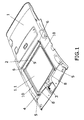
- Figure 1 and 2 are a view from the trim perspective which incorporates the shading device viewed from above. Figure 1 shows the shading element when it is collected and figure 2 when it is extended.
- Figure 3 is a detail of the shading element in its front section where the geared motor is located with the cable winding drum and where the end-stop limitation solutions object of this invention are located. The lower section of the figure shows four details which correspond to the end points where it is most likely that the stresses derived from use or in the reset shall appear.
- Figure 4 is an expanded perspective of the geared motor with the winding drum incorporating a primary solution as an example to prevent the excessive exit of the cable.
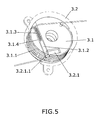
- Figure 5 is a detail of how this same solution functions in the interior of the winding drum.
- Figure 6 is an example of the implementation of the invention which makes it possible to limit and halt the winding of the cable by modifying the drum design.
- Figure 7 is another example of the implementation of the invention also destined to halt and limit the winding of the cable by using external stops.
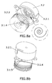
- Figures 8a and 8b represent an implementation mode of the invention in which a limitation is obtained in the drum-casing set both in the extension as well as in the collection of the cable.
- The essential objective, verifying that expressed in the section dedicated to the description of the invention, is to establish an end-stop limit in the exit and entry of the cable which hinders that in operations such as the reset in which these limits are reached, stresses are produced which reach the carrier element of the shading element which shall be the trim in all examples.
- With the support of the figures, several implementation examples shall be described which make it possible to achieve the indicated objective.
- Figure 1 and figure 2 represent trim (1) in which there is a window (1.1) which permits the entry of light and sunshine which pass through the transparent element of the roof, not represented in the figures. This window (1.1) is covered by a shading element which consists in a curtain primarily constituted by a sheet(2).
- It intends to make use of the trim (1) not only as the carrier element but also as a suitably reinforced structural element. With this objective, the trim (1) is placed surrounding the window (1.1) with a resistant frame (4) which incorporates the elements subjected to stress such as the redirectors (5)and the supports (6) of the drum (7).
- In figure 1, the shading element is collected with the sheet (2) completely wound in its drum (7).
- The shading element uses a cable (8) to drive the extension by pulling the front rod (9). This front rod (9) pulls the sheet (2) of the shading element in a uniform way which is displaced so that its ends slide by lateral guides (10).
- The sheet (2) of the shading element is extended starting from its winding drum (7) which is equipped with a spring that always maintains the tendency to wind and collect this sheet (2).
- The traction cable (8) consists of two branches, independent or not, one on each side. This cable (8) is pulled by means of the geared motor (3) which is equipped with an internal winding drum (3.1) covered by a casing (3.2).
- Figure 3 shows the layout of the geared motor (3) in the front part of the trim (1) where it is possible to distinguish the casing (3.2) which covers the internal winding drum (3.1) of the cable (8). Starting from this internal drum (3.1), two branches of cable (8) exit, one on each side, to drive the ends of the rod (9) which drag the sheet (2) of the shading element.
- The geared motor (3) has a reinforced base to absorb the stresses derived from the traction of the cables (8) as well as others derived from the inertia forces. Nevertheless, other zones that require reinforcement such as the support frame (4) of the redirectors (5) and other structural elements which connect them shall be seen as reduced in size and in weight due to the fact that the maximum values of the traction to which they shall be subjected do not include stresses such as those derived from the reset operation.
- To achieve a symmetrical functioning mode in each branch of the cable (8), as shown in the expanded perspective of figure 4, the internal drum (3.1) has in its periphery two sets of symmetrical helicoidal grooves (3.1.1) so that the branch of the cable (8) which is wound in the upper groove (3.1.1) and the branch of the cable (8) which is wound in the lower groove (3.1.1) are performed at the same time and in the same rotation direction. In this way, when rotating the drum (3.1) either the two branches of cable (8) are wound or the two branches of cable (8) are unwound, thus displacing the front rod (9) in a coordinated way in their ends.
- In this solution example, it contains a way to assure that the winding drum (3.1) of the cable (8) is limited at the end of the unwinding route, which means, during the collection of the sheet (2) of the shading element.
- In the winding operation, the cable (8) shall exit from the internal drum (3.1) by means of a window (3.2.1) of the casing (3.2).
- A pin (3.1.2) shall hinder the rotation of the drum (3.1) so that it continues supplying the cable (8).
- This pin (3.1.2) is housed in the interior of the drum (3.1) in a longitudinal cavity (3.1.4) which imposes a single movement option: according to the longitudinal axis of the pin (3.1.2).
- The cavity (3.1.4) in which the pin (3.1.2) is housed emerges in a point of the helicoidal groove (3.1.1) which assures the correct winding of the cable (8) which approximately corresponds to the time when the cable (8) which leaves the groove is near to the end-stop that we want to define.
- The pin (3.1.2) is pressured in a permanent way by the internal spring (3.1.3) which tends to make the pin (3.1.2) exit from its cavity. The wound cable (8) pressures the pin (3.1.2) keeping it inside the cavity (3.1.4) until it reaches the point in which the cable (8) abandons the groove and releases the pin (3.1.2). It has been mentioned above that the cavity emerges in a point of the groove (3.1.1) with a helicoidal configuration approximately near to where the end-stop corresponds because once the pin (3.1.2) is released, this pin (3.1.2) does not make a stop until it has reached the exit window (3.2.1) of the cable (8).
- Consequently, once the pin (3.1.2) is released because it is no longer pressured by the cable (8), the drum (3.1) continues rotating with the pin (3.1.2) making direct contact in the interior surface of the casing (3.2) until it reaches the exit window (3.2.1) of the cable (8) where it makes a stop in one internal side (3.2.1.1) and cannot advance any further. This stop is the one that limits the exit of the cable (8) establishing a stress which does not propagate beyond the geared motor set (3), drum (3.1), and casing (3.2).
- The internal side (3.2.1.1) of the window (3.2.1) of the casing (3.2) where the pin (3.1.2) makes its stop has been represented in figure 5 in a dotted line, where this reference must not be interpreted as an additional part. This side (3.2.1.1) has been shown in the graphic representation for clarity reasons thus indicating where the mechanical interference occurs which hinders the drum (3.1) from continuing to rotate.
- In figure 5, also observe the layout of the pin (3.1.2) in relation to the drum (3.1) where it is housed is not radial but shows a position of its axis separated from the rotation axis of the drum (3.1). This change of direction facilitates the recovery of its retracted position when the rotation direction of the winding drum (3.1) is changed since the retraction force that the interior surface of the casing (3.2)exercises has an action component placed in a way that attempts to prevent jamming. As a result, the force required in this layout of the pin (3.1.2) for its retraction is less giving rise to a smoother behaviour and with a lower requirement in relation to the pair motor.
- Although this solution could be applied to the two sections of cable (8), in the majority of the applications it is sufficient with one that hinders the rotation beyond where it has been predetermined in the design.
- The second implementation example is designed to establish a limitation in the rotation of the drum (3.1) that acts in the opposite direction than the first example. The second example shall establish a limitation mechanism for the rotation of the drum (3.1) at the end of the winding.
- Figure 6 shows a section of the drum (3.1) which coincides with the cavity that houses the pin (3.1.2) and the spring (3.1.3) used in the first example plus a detail of the last section (3.1.1.1) of the groove (3.1.1) .
- This detail shows the depth reduction of the groove (3.1 .1) in such a way that it projects the cable (8) outwards which is supported on it. This exterior projection means that the cable (8) remains imprisoned against the interior surface of the casing (3.2).
- This imprisonment of the cable (8) shall only occur at the end of the winding, after having completed all the turns of the groove (3.1.1) arriving to its final section (3.1.1.1). In this point, the imprisonment hinders the drum (3.1) from continuing to turn establishing a stop that impedes reaching the end-stop in the extension operation of the shading device.
- The third example is a solution that resolves the limitation imposed in the second example in another way, by the extension limit of the shading device.
- This example uses a retention device which acts from the exterior of the casing (3.2).
- In this case, the cable (8) is equipped with a retainer (8.1), which in this implementation example has been designed in the form of a ball, verifying that its size is greater than the window (3.2.1) of the casing (3.2) for the entry of the cable (8) in the internal drum (3.1) where it is wound.
- During the entry of the cable (8), it shall be wound in the drum (3.1) and the retainer (8.1) approaches until the time in which it makes a stop in the window (3.2.1) of the entry since it is not able to surpass it. This obstacle establishes the limitation for the rotation of the winding drum (3.1). Although the retainer (8.1) is externally located, the strain of the cable (8) is produced from the retainer element (8.1) towards the interior of the geared motor (3) and the stresses do not exit from this set, objective of the invention.
- Equivalent to that mentioned in the previous example, although two balls have been represented as the retainer element (8.1), one is sufficient to achieve the retention.
- The fourth example to carry out the limitation as an end-stop mode in the extension and collection operation of the shading element so that the generated stresses remain circumscribed to the geared motor set which has the particular feature of integrating a limitation in both directions in the same solution.
- Figures 8a and 8b only show the internal drum (3.1) where the two branches of the cable (8) are wound and the casing (3.2).
- In its interior side, the casing (3.2) has a canal (3.2.2) or non-bushing slot in the form of a spiral with the ends near to the axis and the external perimeter surface respectively.
- On the other hand, in the internal drum (3.1) there is a pin (3.1.4) in the side which faces the internal side of the casing (3.2) where the canal (3.2.2) is located. This pin (3.1.4) is different from that used in the first example, hence a numerical reference has been used here with a different identification.
- The pin (3.1.4) is partially housed in a non-bushing slot (3.1.5) placed in the internal drum (3.1) and the essentially radial guide.
- The pin (3.1.4) is partially housed because it emerges in a section which is destined to be housed, once the casing (3.2) has been coupled in its operative position in the spiral canal (3.2.2).
- In this functional position, in which the pin (3.1.4) is simultaneously partially inserted in the slot (3.1.5) and the canal (3.2.2), it is necessary to consider the relative movement between each one of the parts.
- The relative rotation between the internal drum (3.1) and the casing (3.2) causes the insertion location of the spiral pin (3.1.4) is radially displaced in relation to the drum (3.1). This radial displacement has two end limits, the one near the rotation axis and the exterior end. This end limit which the pin (3.1.4) reaches in its displacement can be produced either in the spiral canal (3.2.2) or in the slot (3.1.5) of the drum (3.1), although the spiral stop is preferred.
- In the disassembled detail of the spiral, observe that the guide is variable passage. The variable passage makes it possible to adjust for example the support mode in the ends when they make a stop between other stresses; nevertheless a simpler scheme is equally possible based on a constant passage spiral.
- In either of the two cases, the relative movement between the drum (3.1) and the casing (3.2) is found to be impeded simultaneously establishing the two limits or end-stops: one in the extension and the other in the collection of the shading element.
- In the description of the different components of the implementation examples, a single shading element has been used, nevertheless, the application of the invention's essence is possible in configurations of the shading device where two or more curtains are used which are moved at the same time or in an independent way.
Claims (19)
- a.- The shading device for vehicle roofs which comprises a sheet element (2) destined to cover a surface that essentially coincides with a window (1.1) of the roof covered or not covered by a transparent element by itself or in combination with others, extendable from a winding drum (7) which provides a tendency for collection, where it is extendable by traction by means of cable (8), acting on a rigid front rod (9) laterally guided and driven by a geared motor set (3) which incorporates an internal winding drum (3.1) of cable (8) covered by a casing (3.2), characterized because the geared motor set (3) is equipped with limitation devices for the advance in at least one end-stop, either at the end of the extension of the sheet element (2) or at the end of the collection of the sheet element (2) so that once this limitation has been reached, the stresses generated in this limitation do not take place outside the geared motor set (3).
- a.- Shading device for vehicle roofs according to claim 1 characterized because the limitation of the end-stop is established after the collection of the sheet element (2) and corresponding exit of the cable (8).
- a. - Shading device for vehicle roofs according to claim 2 characterized because the limitation of the end-stop is obtained by the mechanical interference that is caused by the exit of a pin (3.1.2) from the internal winding drum (3.1) which is released at the end of the exit of the cable (8) against the casing (3.2).
- a.- Shading device for vehicle roofs according to claim 3 characterized because the pin (3.1.2) is housed in a cavity of the internal winding drum (3.1) of the cable (8).
- a.- Shading device for vehicle roofs according to claim 4 characterized because the cavity is placed in a slanted position in relation to the radial position of the internal drum (3.1).
- a. - Shading device for vehicle roofs according to claim 3 characterized because the pin (3.1.2) is equipped with an internal spring (3.1.3)which possesses the permanent tendency to exit from its housing.
- a. Shading device for vehicle roofs according to claim 3 characterized because the mechanical interference of the pin (3.1.2) with the cavity (3.2) is produced in the exit window (3.2.1) of the cable (8).
- a.- Shading device for vehicle roofs according to claim 1 characterized because the limitation of the end-stop is established after the extension of the sheet element (2) and corresponding collection of the cable (8).
- a.- Shading device for vehicle roofs according to claim 8 characterized because the limitation of the end-stop is obtained by reducing the depth of the winding groove (3.1.1) of the cable (8) in the final stage to obtain the projection of the cable (8) against the casing (3.2) and its imprisonment to obtain a braking effect.
- a. Shading device for vehicle roofs according to claim 8 characterized because the limitation of the end-stop is obtained by the addition of a retainer (8.1) in the entry cable (8) to obtain the mechanical interference with the window (3.1.2) which hinders it from entering due to its smaller dimensions and thus obtains the braking of the internal drum (3.1).
- a.- Shading device for vehicle roofs according to claim 10 characterized because the retainer element (8.1) is a ball.
- a.- Shading device for vehicle roofs according to claim 10 characterized because the redirectors (5) and elements through which the retainer (8.1) passes have been adapted to permit its passage.
- a.- Shading device for vehicle roofs according to claim 1 characterized because the limitation of the end-stop is established in the two directions of the advance: Both in the extension of the shading element as well as in its collection.
- a.- Shading device for vehicle roofs according to claim 13 characterized because the casing (3.2) is equipped with an internal spiral canal (3.2.2) and the internal drum (3.1) with a slot (3.1.5) in an essentially radial layout so that a pin (3.1.4) is found partially housed simultaneously in the canal (3.2.2) and in the slot (3.1.5) so that the relative movement of the rotation between the drum (3.1) and the casing (3.2) displaces the pin (3.1.4) at the end of route or the canal (3.2.2) or the slot (3.1.4) establishing a limit to the advance.
- a. Shading device for vehicle roofs according to claim 14 characterized because the internal spiral canal (3.2.2) is with constant passage.
- a. Shading device for vehicle roofs according to claim 14 characterized because the internal spiral canal (3.2.2) is with variable passage.
- a - Shading device for vehicle roofs according to claim 1 characterized because the window (1.1) is covered by means of a single curtain.
- a.- Shading device for vehicle roofs according to claim 1 characterized because the window (1.1) is covered by means of two or more curtains moved at the same time or in an independent way.
- a. Roof trim module constituted by the trim (1) which incorporates a shading device with limitation devices for the advance based on any of the above claims so that the shading element is found directly attached to the trim (1).
Priority Applications (5)
| Application Number | Priority Date | Filing Date | Title |
|---|---|---|---|
| ES06381022T ES2323811T3 (en) | 2006-05-23 | 2006-05-23 | OCULTATION DEVICE FOR VEHICLE CEILINGS. |
| EP06381022A EP1859979B1 (en) | 2006-05-23 | 2006-05-23 | Shading device for vehicle roofs |
| DE602006007111T DE602006007111D1 (en) | 2006-05-23 | 2006-05-23 | Shading device for a vehicle roof |
| AT06381022T ATE432839T1 (en) | 2006-05-23 | 2006-05-23 | SHADING DEVICE FOR A VEHICLE ROOF |
| PCT/ES2006/070144 WO2007135203A1 (en) | 2006-05-23 | 2006-10-05 | Mask device for vehicle roofs |
Applications Claiming Priority (1)
| Application Number | Priority Date | Filing Date | Title |
|---|---|---|---|
| EP06381022A EP1859979B1 (en) | 2006-05-23 | 2006-05-23 | Shading device for vehicle roofs |
Publications (2)
| Publication Number | Publication Date |
|---|---|
| EP1859979A1 true EP1859979A1 (en) | 2007-11-28 |
| EP1859979B1 EP1859979B1 (en) | 2009-06-03 |
Family
ID=37155906
Family Applications (1)
| Application Number | Title | Priority Date | Filing Date |
|---|---|---|---|
| EP06381022A Not-in-force EP1859979B1 (en) | 2006-05-23 | 2006-05-23 | Shading device for vehicle roofs |
Country Status (5)
| Country | Link |
|---|---|
| EP (1) | EP1859979B1 (en) |
| AT (1) | ATE432839T1 (en) |
| DE (1) | DE602006007111D1 (en) |
| ES (1) | ES2323811T3 (en) |
| WO (1) | WO2007135203A1 (en) |
Citations (3)
| Publication number | Priority date | Publication date | Assignee | Title |
|---|---|---|---|---|
| DE10123422A1 (en) * | 2000-05-15 | 2001-12-06 | Webasto Vehicle Sys Int Gmbh | Drive for vehicle roof movable closure element has cable guided in casing over at least part of length, with casing having extension element for setting length of cable path and hence cable tension |
| EP1258378A2 (en) * | 2001-05-14 | 2002-11-20 | Webasto Vehicle Systems International GmbH | Roller blind for transparent roof element |
| EP1367207A2 (en) * | 2002-05-31 | 2003-12-03 | ArvinMeritor GmbH | Driving device, especially for a vehicle sliding roof, as well as vehicle sliding roof |
Family Cites Families (1)
| Publication number | Priority date | Publication date | Assignee | Title |
|---|---|---|---|---|
| ATE477965T1 (en) | 2005-05-19 | 2010-09-15 | Antolin Grupo Ing Sa | HEADLINER FOR A MOTOR VEHICLE ROOF WITH A TRANSPARENT ELEMENT |
-
2006
- 2006-05-23 AT AT06381022T patent/ATE432839T1/en not_active IP Right Cessation
- 2006-05-23 EP EP06381022A patent/EP1859979B1/en not_active Not-in-force
- 2006-05-23 DE DE602006007111T patent/DE602006007111D1/en not_active Expired - Fee Related
- 2006-05-23 ES ES06381022T patent/ES2323811T3/en active Active
- 2006-10-05 WO PCT/ES2006/070144 patent/WO2007135203A1/en not_active Ceased
Patent Citations (3)
| Publication number | Priority date | Publication date | Assignee | Title |
|---|---|---|---|---|
| DE10123422A1 (en) * | 2000-05-15 | 2001-12-06 | Webasto Vehicle Sys Int Gmbh | Drive for vehicle roof movable closure element has cable guided in casing over at least part of length, with casing having extension element for setting length of cable path and hence cable tension |
| EP1258378A2 (en) * | 2001-05-14 | 2002-11-20 | Webasto Vehicle Systems International GmbH | Roller blind for transparent roof element |
| EP1367207A2 (en) * | 2002-05-31 | 2003-12-03 | ArvinMeritor GmbH | Driving device, especially for a vehicle sliding roof, as well as vehicle sliding roof |
Also Published As
| Publication number | Publication date |
|---|---|
| DE602006007111D1 (en) | 2009-07-16 |
| WO2007135203A1 (en) | 2007-11-29 |
| ES2323811T3 (en) | 2009-07-24 |
| EP1859979B1 (en) | 2009-06-03 |
| ATE432839T1 (en) | 2009-06-15 |
Similar Documents
| Publication | Publication Date | Title |
|---|---|---|
| CN101432159B (en) | Drive device for moving a covering element, door module and method for assembling the drive device | |
| KR20080082927A (en) | Side Window Roller Blinds for Automatic Operation | |
| CN101628538B (en) | Vehicle sunshade device | |
| CN213768228U (en) | Automobile skylight sunshade curtain with inhaul cable driving structure | |
| ITMI980216A1 (en) | VEHICLE | |
| US20210246724A1 (en) | Mechanical module for filtering vibrations, electromechanical actuator comprising such a mechanical module for filtering vibrations, and closure, covering or solar protection installation comprising such an electro-mechanical actuator | |
| CN117227419A (en) | Roof assembly for a vehicle and roller blind assembly for use therein | |
| EP1859979B1 (en) | Shading device for vehicle roofs | |
| US20150300088A1 (en) | Motorized manoeuvring device intended to manoeuvre a moving windable fabric screen of a window or projection screen cover device | |
| CN213705121U (en) | Sun-shading device applied to automobile front windshield | |
| BE1019252A5 (en) | SCREEN DEVICE. | |
| EP3959409B1 (en) | External screening arrangement with a self-adjusting return element | |
| CN221213446U (en) | Roller blind system for vehicle sunroof and vehicle | |
| GB2535506A (en) | Retractable blind system | |
| EP1151881A2 (en) | Sunshade/Sunscreen combo | |
| CN217396181U (en) | Vehicle sunshade curtain and vehicle | |
| KR20100047958A (en) | Device for sun visor of vehicle | |
| EP4006295B1 (en) | A screening arrangement for a roof window, and roof window comprising such a screening arrangement | |
| EP3959407B1 (en) | External screening arrangement with a set of lamellas and method for manufacturing a screening body | |
| US20200198447A1 (en) | Automatic sun visor assembly | |
| CN222136428U (en) | Sunshade and vehicle | |
| CN221194019U (en) | Automatic core adjusting device and corresponding awning | |
| KR101511570B1 (en) | Rear Sunshade With Upper Area Covering Structure | |
| CN217892696U (en) | Vehicle-mounted terminal | |
| CN222179180U (en) | Automatically arranged vehicle-mounted sunshade device |
Legal Events
| Date | Code | Title | Description |
|---|---|---|---|
| PUAI | Public reference made under article 153(3) epc to a published international application that has entered the european phase |
Free format text: ORIGINAL CODE: 0009012 |
|
| AK | Designated contracting states |
Kind code of ref document: A1 Designated state(s): AT BE BG CH CY CZ DE DK EE ES FI FR GB GR HU IE IS IT LI LT LU LV MC NL PL PT RO SE SI SK TR |
|
| AX | Request for extension of the european patent |
Extension state: AL BA HR MK YU |
|
| 17P | Request for examination filed |
Effective date: 20080526 |
|
| AKX | Designation fees paid |
Designated state(s): AT BE BG CH CY CZ DE DK EE ES FI FR GB GR HU IE IS IT LI LT LU LV MC NL PL PT RO SE SI SK TR |
|
| 17Q | First examination report despatched |
Effective date: 20080710 |
|
| GRAP | Despatch of communication of intention to grant a patent |
Free format text: ORIGINAL CODE: EPIDOSNIGR1 |
|
| GRAS | Grant fee paid |
Free format text: ORIGINAL CODE: EPIDOSNIGR3 |
|
| GRAA | (expected) grant |
Free format text: ORIGINAL CODE: 0009210 |
|
| AK | Designated contracting states |
Kind code of ref document: B1 Designated state(s): AT BE BG CH CY CZ DE DK EE ES FI FR GB GR HU IE IS IT LI LT LU LV MC NL PL PT RO SE SI SK TR |
|
| REG | Reference to a national code |
Ref country code: GB Ref legal event code: FG4D |
|
| REG | Reference to a national code |
Ref country code: CH Ref legal event code: EP |
|
| REG | Reference to a national code |
Ref country code: IE Ref legal event code: FG4D |
|
| REF | Corresponds to: |
Ref document number: 602006007111 Country of ref document: DE Date of ref document: 20090716 Kind code of ref document: P |
|
| REG | Reference to a national code |
Ref country code: ES Ref legal event code: FG2A Ref document number: 2323811 Country of ref document: ES Kind code of ref document: T3 |
|
| PG25 | Lapsed in a contracting state [announced via postgrant information from national office to epo] |
Ref country code: FI Free format text: LAPSE BECAUSE OF FAILURE TO SUBMIT A TRANSLATION OF THE DESCRIPTION OR TO PAY THE FEE WITHIN THE PRESCRIBED TIME-LIMIT Effective date: 20090603 Ref country code: AT Free format text: LAPSE BECAUSE OF FAILURE TO SUBMIT A TRANSLATION OF THE DESCRIPTION OR TO PAY THE FEE WITHIN THE PRESCRIBED TIME-LIMIT Effective date: 20090603 Ref country code: LT Free format text: LAPSE BECAUSE OF FAILURE TO SUBMIT A TRANSLATION OF THE DESCRIPTION OR TO PAY THE FEE WITHIN THE PRESCRIBED TIME-LIMIT Effective date: 20090603 |
|
| NLV1 | Nl: lapsed or annulled due to failure to fulfill the requirements of art. 29p and 29m of the patents act | ||
| PG25 | Lapsed in a contracting state [announced via postgrant information from national office to epo] |
Ref country code: LV Free format text: LAPSE BECAUSE OF FAILURE TO SUBMIT A TRANSLATION OF THE DESCRIPTION OR TO PAY THE FEE WITHIN THE PRESCRIBED TIME-LIMIT Effective date: 20090603 Ref country code: PL Free format text: LAPSE BECAUSE OF FAILURE TO SUBMIT A TRANSLATION OF THE DESCRIPTION OR TO PAY THE FEE WITHIN THE PRESCRIBED TIME-LIMIT Effective date: 20090603 Ref country code: NL Free format text: LAPSE BECAUSE OF FAILURE TO SUBMIT A TRANSLATION OF THE DESCRIPTION OR TO PAY THE FEE WITHIN THE PRESCRIBED TIME-LIMIT Effective date: 20090603 Ref country code: SI Free format text: LAPSE BECAUSE OF FAILURE TO SUBMIT A TRANSLATION OF THE DESCRIPTION OR TO PAY THE FEE WITHIN THE PRESCRIBED TIME-LIMIT Effective date: 20090603 Ref country code: SE Free format text: LAPSE BECAUSE OF FAILURE TO SUBMIT A TRANSLATION OF THE DESCRIPTION OR TO PAY THE FEE WITHIN THE PRESCRIBED TIME-LIMIT Effective date: 20090903 |
|
| PG25 | Lapsed in a contracting state [announced via postgrant information from national office to epo] |
Ref country code: CZ Free format text: LAPSE BECAUSE OF FAILURE TO SUBMIT A TRANSLATION OF THE DESCRIPTION OR TO PAY THE FEE WITHIN THE PRESCRIBED TIME-LIMIT Effective date: 20090603 Ref country code: RO Free format text: LAPSE BECAUSE OF FAILURE TO SUBMIT A TRANSLATION OF THE DESCRIPTION OR TO PAY THE FEE WITHIN THE PRESCRIBED TIME-LIMIT Effective date: 20090603 Ref country code: EE Free format text: LAPSE BECAUSE OF FAILURE TO SUBMIT A TRANSLATION OF THE DESCRIPTION OR TO PAY THE FEE WITHIN THE PRESCRIBED TIME-LIMIT Effective date: 20090603 Ref country code: IS Free format text: LAPSE BECAUSE OF FAILURE TO SUBMIT A TRANSLATION OF THE DESCRIPTION OR TO PAY THE FEE WITHIN THE PRESCRIBED TIME-LIMIT Effective date: 20091003 |
|
| PG25 | Lapsed in a contracting state [announced via postgrant information from national office to epo] |
Ref country code: SK Free format text: LAPSE BECAUSE OF FAILURE TO SUBMIT A TRANSLATION OF THE DESCRIPTION OR TO PAY THE FEE WITHIN THE PRESCRIBED TIME-LIMIT Effective date: 20090603 Ref country code: BE Free format text: LAPSE BECAUSE OF FAILURE TO SUBMIT A TRANSLATION OF THE DESCRIPTION OR TO PAY THE FEE WITHIN THE PRESCRIBED TIME-LIMIT Effective date: 20090603 |
|
| PG25 | Lapsed in a contracting state [announced via postgrant information from national office to epo] |
Ref country code: BG Free format text: LAPSE BECAUSE OF FAILURE TO SUBMIT A TRANSLATION OF THE DESCRIPTION OR TO PAY THE FEE WITHIN THE PRESCRIBED TIME-LIMIT Effective date: 20090903 Ref country code: PT Free format text: LAPSE BECAUSE OF FAILURE TO SUBMIT A TRANSLATION OF THE DESCRIPTION OR TO PAY THE FEE WITHIN THE PRESCRIBED TIME-LIMIT Effective date: 20091003 |
|
| PLBE | No opposition filed within time limit |
Free format text: ORIGINAL CODE: 0009261 |
|
| STAA | Information on the status of an ep patent application or granted ep patent |
Free format text: STATUS: NO OPPOSITION FILED WITHIN TIME LIMIT |
|
| PG25 | Lapsed in a contracting state [announced via postgrant information from national office to epo] |
Ref country code: DK Free format text: LAPSE BECAUSE OF FAILURE TO SUBMIT A TRANSLATION OF THE DESCRIPTION OR TO PAY THE FEE WITHIN THE PRESCRIBED TIME-LIMIT Effective date: 20090603 |
|
| 26N | No opposition filed |
Effective date: 20100304 |
|
| PG25 | Lapsed in a contracting state [announced via postgrant information from national office to epo] |
Ref country code: GR Free format text: LAPSE BECAUSE OF FAILURE TO SUBMIT A TRANSLATION OF THE DESCRIPTION OR TO PAY THE FEE WITHIN THE PRESCRIBED TIME-LIMIT Effective date: 20090904 |
|
| PG25 | Lapsed in a contracting state [announced via postgrant information from national office to epo] |
Ref country code: MC Free format text: LAPSE BECAUSE OF NON-PAYMENT OF DUE FEES Effective date: 20100531 |
|
| REG | Reference to a national code |
Ref country code: CH Ref legal event code: PL |
|
| GBPC | Gb: european patent ceased through non-payment of renewal fee |
Effective date: 20100523 |
|
| REG | Reference to a national code |
Ref country code: FR Ref legal event code: ST Effective date: 20110131 |
|
| PG25 | Lapsed in a contracting state [announced via postgrant information from national office to epo] |
Ref country code: LI Free format text: LAPSE BECAUSE OF NON-PAYMENT OF DUE FEES Effective date: 20100531 Ref country code: CH Free format text: LAPSE BECAUSE OF NON-PAYMENT OF DUE FEES Effective date: 20100531 |
|
| REG | Reference to a national code |
Ref country code: IE Ref legal event code: MM4A |
|
| PG25 | Lapsed in a contracting state [announced via postgrant information from national office to epo] |
Ref country code: IT Free format text: LAPSE BECAUSE OF FAILURE TO SUBMIT A TRANSLATION OF THE DESCRIPTION OR TO PAY THE FEE WITHIN THE PRESCRIBED TIME-LIMIT Effective date: 20090603 |
|
| PG25 | Lapsed in a contracting state [announced via postgrant information from national office to epo] |
Ref country code: IE Free format text: LAPSE BECAUSE OF NON-PAYMENT OF DUE FEES Effective date: 20100523 Ref country code: DE Free format text: LAPSE BECAUSE OF NON-PAYMENT OF DUE FEES Effective date: 20101201 |
|
| PG25 | Lapsed in a contracting state [announced via postgrant information from national office to epo] |
Ref country code: FR Free format text: LAPSE BECAUSE OF NON-PAYMENT OF DUE FEES Effective date: 20100531 |
|
| PG25 | Lapsed in a contracting state [announced via postgrant information from national office to epo] |
Ref country code: GB Free format text: LAPSE BECAUSE OF NON-PAYMENT OF DUE FEES Effective date: 20100523 |
|
| PG25 | Lapsed in a contracting state [announced via postgrant information from national office to epo] |
Ref country code: CY Free format text: LAPSE BECAUSE OF FAILURE TO SUBMIT A TRANSLATION OF THE DESCRIPTION OR TO PAY THE FEE WITHIN THE PRESCRIBED TIME-LIMIT Effective date: 20090603 |
|
| PG25 | Lapsed in a contracting state [announced via postgrant information from national office to epo] |
Ref country code: LU Free format text: LAPSE BECAUSE OF NON-PAYMENT OF DUE FEES Effective date: 20100523 Ref country code: HU Free format text: LAPSE BECAUSE OF FAILURE TO SUBMIT A TRANSLATION OF THE DESCRIPTION OR TO PAY THE FEE WITHIN THE PRESCRIBED TIME-LIMIT Effective date: 20091204 |
|
| PG25 | Lapsed in a contracting state [announced via postgrant information from national office to epo] |
Ref country code: TR Free format text: LAPSE BECAUSE OF FAILURE TO SUBMIT A TRANSLATION OF THE DESCRIPTION OR TO PAY THE FEE WITHIN THE PRESCRIBED TIME-LIMIT Effective date: 20090603 |
|
| PGFP | Annual fee paid to national office [announced via postgrant information from national office to epo] |
Ref country code: ES Payment date: 20150304 Year of fee payment: 10 |
|
| PG25 | Lapsed in a contracting state [announced via postgrant information from national office to epo] |
Ref country code: ES Free format text: LAPSE BECAUSE OF NON-PAYMENT OF DUE FEES Effective date: 20160524 |
|
| REG | Reference to a national code |
Ref country code: ES Ref legal event code: FD2A Effective date: 20181205 |