EP1859741A2 - Apparatus and method for displaying an ultrasound image - Google Patents
Apparatus and method for displaying an ultrasound image Download PDFInfo
- Publication number
- EP1859741A2 EP1859741A2 EP07007568A EP07007568A EP1859741A2 EP 1859741 A2 EP1859741 A2 EP 1859741A2 EP 07007568 A EP07007568 A EP 07007568A EP 07007568 A EP07007568 A EP 07007568A EP 1859741 A2 EP1859741 A2 EP 1859741A2
- Authority
- EP
- European Patent Office
- Prior art keywords
- dimensional ultrasound
- ultrasound image
- dimensional
- images
- cutting
- Prior art date
- Legal status (The legal status is an assumption and is not a legal conclusion. Google has not performed a legal analysis and makes no representation as to the accuracy of the status listed.)
- Withdrawn
Links
Images


Classifications
-
- A—HUMAN NECESSITIES
- A61—MEDICAL OR VETERINARY SCIENCE; HYGIENE
- A61B—DIAGNOSIS; SURGERY; IDENTIFICATION
- A61B8/00—Diagnosis using ultrasonic, sonic or infrasonic waves
-
- A—HUMAN NECESSITIES
- A61—MEDICAL OR VETERINARY SCIENCE; HYGIENE
- A61B—DIAGNOSIS; SURGERY; IDENTIFICATION
- A61B8/00—Diagnosis using ultrasonic, sonic or infrasonic waves
- A61B8/08—Clinical applications
-
- A—HUMAN NECESSITIES
- A61—MEDICAL OR VETERINARY SCIENCE; HYGIENE
- A61B—DIAGNOSIS; SURGERY; IDENTIFICATION
- A61B8/00—Diagnosis using ultrasonic, sonic or infrasonic waves
- A61B8/46—Ultrasonic, sonic or infrasonic diagnostic devices with special arrangements for interfacing with the operator or the patient
- A61B8/461—Displaying means of special interest
- A61B8/465—Displaying means of special interest adapted to display user selection data, e.g. icons or menus
-
- A—HUMAN NECESSITIES
- A61—MEDICAL OR VETERINARY SCIENCE; HYGIENE
- A61B—DIAGNOSIS; SURGERY; IDENTIFICATION
- A61B8/00—Diagnosis using ultrasonic, sonic or infrasonic waves
- A61B8/48—Diagnostic techniques
- A61B8/483—Diagnostic techniques involving the acquisition of a 3D volume of data
-
- G—PHYSICS
- G01—MEASURING; TESTING
- G01S—RADIO DIRECTION-FINDING; RADIO NAVIGATION; DETERMINING DISTANCE OR VELOCITY BY USE OF RADIO WAVES; LOCATING OR PRESENCE-DETECTING BY USE OF THE REFLECTION OR RERADIATION OF RADIO WAVES; ANALOGOUS ARRANGEMENTS USING OTHER WAVES
- G01S15/00—Systems using the reflection or reradiation of acoustic waves, e.g. sonar systems
- G01S15/88—Sonar systems specially adapted for specific applications
- G01S15/89—Sonar systems specially adapted for specific applications for mapping or imaging
- G01S15/8906—Short-range imaging systems; Acoustic microscope systems using pulse-echo techniques
- G01S15/8993—Three dimensional imaging systems
-
- G—PHYSICS
- G06—COMPUTING OR CALCULATING; COUNTING
- G06T—IMAGE DATA PROCESSING OR GENERATION, IN GENERAL
- G06T19/00—Manipulating three-dimensional [3D] models or images for computer graphics
-
- A—HUMAN NECESSITIES
- A61—MEDICAL OR VETERINARY SCIENCE; HYGIENE
- A61B—DIAGNOSIS; SURGERY; IDENTIFICATION
- A61B8/00—Diagnosis using ultrasonic, sonic or infrasonic waves
- A61B8/48—Diagnostic techniques
- A61B8/486—Diagnostic techniques involving arbitrary m-mode
-
- G—PHYSICS
- G06—COMPUTING OR CALCULATING; COUNTING
- G06T—IMAGE DATA PROCESSING OR GENERATION, IN GENERAL
- G06T2219/00—Indexing scheme for manipulating 3D models or images for computer graphics
- G06T2219/008—Cut plane or projection plane definition
Definitions
- the present invention generally relates to ultrasound image processing, and more particularly to an apparatus and method for displaying a 3-dimensional ultrasound image formed by superposing a plurality of 2-dimensional ultrasound images.
- An ultrasound diagnostic system has become an important and popular diagnostic tool since it has a wide range of applications. Specifically, due to its non-invasive and non-destructive nature, the ultrasound diagnostic system has been extensively used in the medical profession. Modem high-performance ultrasound diagnostic systems and techniques are commonly used to produce two or three-dimensional diagnostic images of internal features of an object (e.g., human organs).
- an object e.g., human organs
- the ultrasound diagnostic system generally uses a wide bandwidth transducer to transmit and receive ultrasound signals.
- the ultrasound diagnostic system forms images of human internal tissues by electrically exciting an acoustic transducer element or an array of acoustic transducer elements to generate ultrasound signals that travel into the body.
- the ultrasound signals produce ultrasound echo signals since they are reflected from body tissues, which appear as discontinuities to the propagating ultrasound signals.
- Various ultrasound echo signals return to the transducer element and are converted into electrical signals, which are amplified and processed to produce ultrasound data for an image of the tissues.
- the ultrasound diagnostic system is very important in the medical field since it provides physicians with real-time and high-resolution images of human internal features without the need for invasive observation techniques such as surgery.
- the ultrasound diagnostic system obtains raw 3D data (e.g., data on a coordinate system (x, y, z)) through a 3D probe by stacking consecutive frames. It then processes the consecutive frames using a 3D rendering technique, thereby producing 3D static images.
- raw 3D data e.g., data on a coordinate system (x, y, z)
- 3D rendering technique e.g., 3D rendering technique
- the static 3D images are widely used.
- the static 3D images are not useful in observing a moving target object in real time, such as a heart and a fetus in the uterus.
- a live 3D imaging method and apparatus for providing a live 3D moving image have been developed.
- the 3-dimensional probe for forming a live 3D ultrasound image is disadvantageous since it is very complex and expensive.
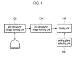
- FIG. 1 is a block diagram showing an ultrasound diagnostic system constructed in accordance with the present invention
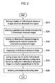
- FIG. 2 is a flowchart illustrating a method of displaying an ultrasound image in accordance with an embodiment of the present invention
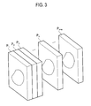
- FIG. 3 is a schematic diagram illustrating a plurality of 2-dimensional ultrasound images formed based on ultrasound echo signals reflected from a predetermined region of a target object;
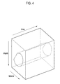
- FIG. 4 is a schematic diagram illustrating a 3-dimensional ultrasound image formed by superposing a plurality of 2-dimensional ultrasound images
- FIG. 5 is a schematic diagram showing a 3-dimensional ultrasound image formed by superposing a plurality of 2-dimensional ultrasound images when movement occurs.
- FIG. 6 is a schematic diagram showing an example of setting an oblique line on the 3-dimensional ultrasound image illustrated in FIG. 5.
- FIG. 1 is a block diagram showing an ultrasound diagnostic system constructed in accordance with the present invention.
- the ultrasound diagnostic system 100 includes a probe 110, a 2-dimensional ultrasound image forming unit 120, a 3-dimensional ultrasound image forming unit 130, a display unit 140 and a cutting plane selecting unit 150.
- the probe 110 transmits ultrasound signals to a target object and receives ultrasound echo signals.
- the probe 110 may be any probe capable of acquiring a 2-dimensional ultrasound image.
- the 2-dimensional ultrasound image forming unit 120 forms a plurality of 2-dimensional ultrasound images having serial numbers based on the ultrasound echo signals reflected from a predetermined region of a target object.
- the 2-dimensional ultrasound images may be one of B-mode images, Doppler images and color-mode images.
- the serial number may be set in an order of acquisition time of the 2-dimensional ultrasound images.
- the 3-dimensional ultrasound image forming unit 130 forms a 3-dimensional ultrasound image based on the plurality of 2-dimensional ultrasound images.
- the 3-dimensional ultrasound image forming unit 130 selects a predetermined number of 2-dimensional ultrasound images in accordance with one embodiment of the present invention.
- the selected 2-dimensional ultrasound images are sequentially buffered and then superposed, thereby forming the 3-dimensional ultrasound image.
- the 3-dimensional ultrasound image forming unit 130 may individually render the selected 2-dimensional ultrasound images and can then superpose them in order to form the 3-dimensional ultrasound image.
- the 3-dimensional ultrasound image forming unit 130 may set a region of interest (ROI) in each 2-dimensional ultrasound images and then extracts the images included in the ROIs.
- the 3-dimensional ultrasound image forming unit 130 can superpose the extracted images, thereby forming the 3-dimensional ultrasound image.
- ROI region of interest
- the 3-dimensional ultrasound image forming unit 130 may provide a transparent 3-dimensional ultrasound image obtained by an appropriate transparency treatment for showing a volume of interest (VOI) in the 3-dimensional ultrasound image.
- VOI volume of interest
- the 3-dimensional ultrasound image or the transparent 3-dimensional ultrasound image formed in the 3-dimensional ultrasound image forming unit 130 is transmitted to the display unit and then displayed on a screen of the display unit 140.
- the cutting plane selecting unit 150 receives a line setting instruction from a user and sets at least one line on the 3-dimensional ultrasound image displayed on the display unit 140 in response to the line setting instruction.
- the line setting instruction may be inputted by using a control key (not denoted) provided in the ultrasound diagnostic system to set an arbitrary line on the 3-dimensional ultrasound image.
- the cutting plane selecting unit 150 cuts the 3-dimensional ultrasound image along the line in a depth direction and then selects one of the cutting planes.
- the selected plane is rendered, wherein the rendered plane image is then displayed on the display unit 140.
- a plurality of lines may be set on the 3-dimensional ultrasound image and the rendering of the cutting plane may be performed by using an anti-aliasing technique.
- FIG. 2 is a flowchart illustrating a method of displaying the ultrasound image in accordance with one embodiment of the present invention.
- the 2-dimensional ultrasound image forming unit 120 forms a plurality of 2-dimensional ultrasound images in real time based on the ultrasound echo signals, which are reflected from a predetermined region of a target object, as shown in FIG. 3 at step S210.
- Serial numbers P 1 -P n+m may be assigned to each 2-dimensional ultrasound image.
- the serial numbers assigned to the 2-dimensional ultrasound images may be set in an order of acquisition time of the 2-dimensional ultrasound images.
- the 3-dimensional ultrasound image forming unit 130 selects a predetermined number of 2-dimensional ultrasound images having consecutive serial numbers among the 2-dimensional ultrasound images at step S220.
- the selected 2-dimensional ultrasound images are superposed to thereby form a 3-dimensional ultrasound image at step S230.
- the 3-dimensional ultrasound image is displayed on the display unit 140 at step S240, as shown in FIG. 4. Thereafter, at least one line is set on the displayed 3-dimensional ultrasound image and then one cutting plane obtained by cutting the 3-dimensional ultrasound image in a depth direction is selected at step S250.
- the selected cutting plane is displayed on the display unit 240 at step S260.
- the cutting plane may be rendered by using the anti-aliasing technique and then displayed on the display unit 140.
- FIG. 5 is a schematic diagram showing a 3-dimensional ultrasound image formed by superposing 2-dimensional ultrasound images when the movement occurs.
- FIG. 6 is a schematic diagram showing an example of setting an oblique line on the 3-dimensional ultrasound image illustrated in FIG. 5.
- an arbitrary oblique line may be set on a desirable portion in the 3-dimensional ultrasound image.
- the 3-dimensional ultrasound image is then cut along the oblique line in a depth direction.
- One of the cutting planes may be selected, wherein the selected cutting plane is rendered.
- the rendered plane is then displayed on the display unit 140.
- the 3-dimensional ultrasound image is formed by superposing the 2-dimensional ultrasound images in accordance with one embodiment of the present invention. As such, the 3-dimensional ultrasound image can be provided without using an expensive 3-dimensional probe.
- the oblique line can be set on the 3-dimensional ultrasound image formed by superposing the 2-dimensional ultrasound images in accordance with the present invention, the user can see the disable plane in the 3-dimensional ultrasound image even if the movement occurs in acquiring the 2-dimensional ultrasound images.
- a method of displaying an ultrasound image in an ultrasound diagnostic system comprises: a) forming a plurality of sequential 2-dimensional ultrasound images based on ultrasound echo signals reflected from a predetermined region of a target object; b) selecting a predetermined number of consecutive 2-dimensional ultrasound images from the plurality of 2-dimensional ultrasound images; c) superposing the selected 2-dimensional ultrasound images to form a 3-dimensional ultrasound image; d) setting at least one line on the 3-dimensional ultrasound image; e) cutting the 3-dimensional ultrasound image along the line to obtain a plurality of cutting planes; f) selecting one cutting plane from the plurality of cutting planes; and g) rendering the selected cutting plane and displaying the rendered cutting plane.
- An apparatus of displaying an ultrasound image in an ultrasound diagnostic system comprises: a probe for transmitting ultrasound signals into a target object and receiving ultrasound echo signals; a 2-dimensional ultrasound image forming unit for forming a plurality of 2-dimensional ultrasound images based on the ultrasound image signals reflected from a predetermined region of a target object; a 3-dimensional ultrasound image forming unit for selecting a predetermined number of consecutive 2-dimensional ultrasound images and superposing the selected 2-dimensional ultrasound images, thereby forming a 3-dimensional ultrasound image; a cutting plane selecting unit for setting at least one line on the 3-dimensional ultrasound image and cutting the 3-dimensional ultrasound image along the line to obtain a plurality of cutting planes, wherein the cutting plane selecting unit is configured to select one cutting plane from the plurality of cutting planes; and a displaying unit for displaying the 3-dimensional ultrasound image and the cutting plane.
- any reference in this specification to "one embodiment,” “an embodiment,” “example embodiment,” etc. means that a particular feature, structure or characteristic described in connection with the embodiment is included in at least one embodiment of the invention.
- the appearances of such phrases in various places in the specification are not necessarily all referring to the same embodiment.
Landscapes
- Life Sciences & Earth Sciences (AREA)
- Health & Medical Sciences (AREA)
- Engineering & Computer Science (AREA)
- Physics & Mathematics (AREA)
- General Health & Medical Sciences (AREA)
- Medical Informatics (AREA)
- Veterinary Medicine (AREA)
- Public Health (AREA)
- Animal Behavior & Ethology (AREA)
- Surgery (AREA)
- Molecular Biology (AREA)
- Biophysics (AREA)
- Nuclear Medicine, Radiotherapy & Molecular Imaging (AREA)
- Pathology (AREA)
- Radiology & Medical Imaging (AREA)
- Biomedical Technology (AREA)
- Heart & Thoracic Surgery (AREA)
- Radar, Positioning & Navigation (AREA)
- Remote Sensing (AREA)
- General Physics & Mathematics (AREA)
- Acoustics & Sound (AREA)
- Software Systems (AREA)
- Computer Hardware Design (AREA)
- General Engineering & Computer Science (AREA)
- Human Computer Interaction (AREA)
- Computer Graphics (AREA)
- Theoretical Computer Science (AREA)
- Computer Networks & Wireless Communication (AREA)
- Ultra Sonic Daignosis Equipment (AREA)
Abstract
Description
- The present application claims priority from
Korean Patent Application No. 10-2006-0046603 filed on May 24, 2006 - The present invention generally relates to ultrasound image processing, and more particularly to an apparatus and method for displaying a 3-dimensional ultrasound image formed by superposing a plurality of 2-dimensional ultrasound images.
- An ultrasound diagnostic system has become an important and popular diagnostic tool since it has a wide range of applications. Specifically, due to its non-invasive and non-destructive nature, the ultrasound diagnostic system has been extensively used in the medical profession. Modem high-performance ultrasound diagnostic systems and techniques are commonly used to produce two or three-dimensional diagnostic images of internal features of an object (e.g., human organs).
- The ultrasound diagnostic system generally uses a wide bandwidth transducer to transmit and receive ultrasound signals. The ultrasound diagnostic system forms images of human internal tissues by electrically exciting an acoustic transducer element or an array of acoustic transducer elements to generate ultrasound signals that travel into the body. The ultrasound signals produce ultrasound echo signals since they are reflected from body tissues, which appear as discontinuities to the propagating ultrasound signals. Various ultrasound echo signals return to the transducer element and are converted into electrical signals, which are amplified and processed to produce ultrasound data for an image of the tissues. The ultrasound diagnostic system is very important in the medical field since it provides physicians with real-time and high-resolution images of human internal features without the need for invasive observation techniques such as surgery.
- Generally, the ultrasound diagnostic system obtains raw 3D data (e.g., data on a coordinate system (x, y, z)) through a 3D probe by stacking consecutive frames. It then processes the consecutive frames using a 3D rendering technique, thereby producing 3D static images. By using the static 3D images for ultrasound diagnostic purposes, one may easily and accurately observe, diagnose and treat the internal state of a human body without performing any complicated procedures associated with invasive operations. Thus, the static 3D images are widely used. However, the static 3D images are not useful in observing a moving target object in real time, such as a heart and a fetus in the uterus.
- In order to overcome this shortcoming, a live 3D imaging method and apparatus for providing a live 3D moving image (rather than static 3D images) have been developed. However, it is impossible to scan the entire motion of a heart by using a 3-dimensional probe for live 3D imaging due to the limitations in hardware capability. Therefore, there is a problem in that a change of motion at a specific region of the heart cannot be observed in real time. Also, the 3-dimensional probe for forming a live 3D ultrasound image is disadvantageous since it is very complex and expensive.
- Accordingly, there is a strong need in the art to form a 3-dimensional ultrasound image in real time without using a 3-dimensional probe.
- Arrangements and embodiments may be described in detail with reference to the following drawings in which like reference numerals refer to like elements and wherein:
- FIG. 1 is a block diagram showing an ultrasound diagnostic system constructed in accordance with the present invention;
- FIG. 2 is a flowchart illustrating a method of displaying an ultrasound image in accordance with an embodiment of the present invention;
- FIG. 3 is a schematic diagram illustrating a plurality of 2-dimensional ultrasound images formed based on ultrasound echo signals reflected from a predetermined region of a target object;
- FIG. 4 is a schematic diagram illustrating a 3-dimensional ultrasound image formed by superposing a plurality of 2-dimensional ultrasound images;
- FIG. 5 is a schematic diagram showing a 3-dimensional ultrasound image formed by superposing a plurality of 2-dimensional ultrasound images when movement occurs; and
- FIG. 6 is a schematic diagram showing an example of setting an oblique line on the 3-dimensional ultrasound image illustrated in FIG. 5.
- A detailed description may be provided with reference to the accompanying drawings. One of ordinary skill in the art may realize that the following description is illustrative only and is not in any way limiting. Other embodiments of the present invention may readily suggest themselves to such skilled persons having the benefit of this disclosure.
- FIG. 1 is a block diagram showing an ultrasound diagnostic system constructed in accordance with the present invention. As shown in FIG. 1, the ultrasound diagnostic system 100 includes a probe 110, a 2-dimensional ultrasound
image forming unit 120, a 3-dimensional ultrasoundimage forming unit 130, adisplay unit 140 and a cuttingplane selecting unit 150. The probe 110 transmits ultrasound signals to a target object and receives ultrasound echo signals. The probe 110 may be any probe capable of acquiring a 2-dimensional ultrasound image. - The 2-dimensional ultrasound
image forming unit 120 forms a plurality of 2-dimensional ultrasound images having serial numbers based on the ultrasound echo signals reflected from a predetermined region of a target object. The 2-dimensional ultrasound images may be one of B-mode images, Doppler images and color-mode images. The serial number may be set in an order of acquisition time of the 2-dimensional ultrasound images. - The 3-dimensional ultrasound
image forming unit 130 forms a 3-dimensional ultrasound image based on the plurality of 2-dimensional ultrasound images. The 3-dimensional ultrasoundimage forming unit 130 selects a predetermined number of 2-dimensional ultrasound images in accordance with one embodiment of the present invention. The selected 2-dimensional ultrasound images are sequentially buffered and then superposed, thereby forming the 3-dimensional ultrasound image. Also, the 3-dimensional ultrasoundimage forming unit 130 may individually render the selected 2-dimensional ultrasound images and can then superpose them in order to form the 3-dimensional ultrasound image. - In accordance with another embodiment of the present invention, the 3-dimensional ultrasound
image forming unit 130 may set a region of interest (ROI) in each 2-dimensional ultrasound images and then extracts the images included in the ROIs. The 3-dimensional ultrasoundimage forming unit 130 can superpose the extracted images, thereby forming the 3-dimensional ultrasound image. - The 3-dimensional ultrasound
image forming unit 130 may provide a transparent 3-dimensional ultrasound image obtained by an appropriate transparency treatment for showing a volume of interest (VOI) in the 3-dimensional ultrasound image. The 3-dimensional ultrasound image or the transparent 3-dimensional ultrasound image formed in the 3-dimensional ultrasoundimage forming unit 130 is transmitted to the display unit and then displayed on a screen of thedisplay unit 140. - The cutting
plane selecting unit 150 receives a line setting instruction from a user and sets at least one line on the 3-dimensional ultrasound image displayed on thedisplay unit 140 in response to the line setting instruction. The line setting instruction may be inputted by using a control key (not denoted) provided in the ultrasound diagnostic system to set an arbitrary line on the 3-dimensional ultrasound image. The cuttingplane selecting unit 150 cuts the 3-dimensional ultrasound image along the line in a depth direction and then selects one of the cutting planes. The selected plane is rendered, wherein the rendered plane image is then displayed on thedisplay unit 140. A plurality of lines may be set on the 3-dimensional ultrasound image and the rendering of the cutting plane may be performed by using an anti-aliasing technique. - Hereinafter, a method of displaying an ultrasound image will be described in detail with reference to FIGS. 2 to 6. FIG. 2 is a flowchart illustrating a method of displaying the ultrasound image in accordance with one embodiment of the present invention.
- Referring to FIG. 2, the 2-dimensional ultrasound
image forming unit 120 forms a plurality of 2-dimensional ultrasound images in real time based on the ultrasound echo signals, which are reflected from a predetermined region of a target object, as shown in FIG. 3 at step S210. Serial numbers P1-Pn+m may be assigned to each 2-dimensional ultrasound image. The serial numbers assigned to the 2-dimensional ultrasound images may be set in an order of acquisition time of the 2-dimensional ultrasound images. The 3-dimensional ultrasoundimage forming unit 130 selects a predetermined number of 2-dimensional ultrasound images having consecutive serial numbers among the 2-dimensional ultrasound images at step S220. - The selected 2-dimensional ultrasound images are superposed to thereby form a 3-dimensional ultrasound image at step S230. The 3-dimensional ultrasound image is displayed on the
display unit 140 at step S240, as shown in FIG. 4. Thereafter, at least one line is set on the displayed 3-dimensional ultrasound image and then one cutting plane obtained by cutting the 3-dimensional ultrasound image in a depth direction is selected at step S250. The selected cutting plane is displayed on the display unit 240 at step S260. The cutting plane may be rendered by using the anti-aliasing technique and then displayed on thedisplay unit 140. - Further, when the 2-dimensional ultrasound images are acquired, the movement of the 2-dimensional ultrasound images may occur due to trembling hands, heart beats or movements of a target object. FIG. 5 is a schematic diagram showing a 3-dimensional ultrasound image formed by superposing 2-dimensional ultrasound images when the movement occurs.
- FIG. 6 is a schematic diagram showing an example of setting an oblique line on the 3-dimensional ultrasound image illustrated in FIG. 5. As shown in FIG. 6, an arbitrary oblique line may be set on a desirable portion in the 3-dimensional ultrasound image. The 3-dimensional ultrasound image is then cut along the oblique line in a depth direction. One of the cutting planes may be selected, wherein the selected cutting plane is rendered. The rendered plane is then displayed on the
display unit 140. - As mentioned above, the 3-dimensional ultrasound image is formed by superposing the 2-dimensional ultrasound images in accordance with one embodiment of the present invention. As such, the 3-dimensional ultrasound image can be provided without using an expensive 3-dimensional probe.
- Also, since the oblique line can be set on the 3-dimensional ultrasound image formed by superposing the 2-dimensional ultrasound images in accordance with the present invention, the user can see the disable plane in the 3-dimensional ultrasound image even if the movement occurs in acquiring the 2-dimensional ultrasound images.
- A method of displaying an ultrasound image in an ultrasound diagnostic system, comprises: a) forming a plurality of sequential 2-dimensional ultrasound images based on ultrasound echo signals reflected from a predetermined region of a target object; b) selecting a predetermined number of consecutive 2-dimensional ultrasound images from the plurality of 2-dimensional ultrasound images; c) superposing the selected 2-dimensional ultrasound images to form a 3-dimensional ultrasound image; d) setting at least one line on the 3-dimensional ultrasound image; e) cutting the 3-dimensional ultrasound image along the line to obtain a plurality of cutting planes; f) selecting one cutting plane from the plurality of cutting planes; and g) rendering the selected cutting plane and displaying the rendered cutting plane.
- An apparatus of displaying an ultrasound image in an ultrasound diagnostic system, comprises: a probe for transmitting ultrasound signals into a target object and receiving ultrasound echo signals; a 2-dimensional ultrasound image forming unit for forming a plurality of 2-dimensional ultrasound images based on the ultrasound image signals reflected from a predetermined region of a target object; a 3-dimensional ultrasound image forming unit for selecting a predetermined number of consecutive 2-dimensional ultrasound images and superposing the selected 2-dimensional ultrasound images, thereby forming a 3-dimensional ultrasound image; a cutting plane selecting unit for setting at least one line on the 3-dimensional ultrasound image and cutting the 3-dimensional ultrasound image along the line to obtain a plurality of cutting planes, wherein the cutting plane selecting unit is configured to select one cutting plane from the plurality of cutting planes; and a displaying unit for displaying the 3-dimensional ultrasound image and the cutting plane.
- Any reference in this specification to "one embodiment," "an embodiment," "example embodiment," etc., means that a particular feature, structure or characteristic described in connection with the embodiment is included in at least one embodiment of the invention. The appearances of such phrases in various places in the specification are not necessarily all referring to the same embodiment. Further, when a particular feature, structure or characteristic is described in connection with any embodiment, it is submitted that it is within the purview of one skilled in the art to effect such feature, structure or characteristic in connection with other ones of the embodiments.
- Although embodiments have been described with reference to a number of illustrative embodiments thereof, it should be understood that numerous other modifications and embodiments can be devised by those skilled in the art that will fall within the spirit and scope of the principles of this disclosure. More particularly, numerous variations and modifications are possible in the component parts and/or arrangements of the subject combination arrangement within the scope of the disclosure, the drawings and the appended claims. In addition to variations and modifications in the component parts and/or arrangements, alternative uses will also be apparent to those skilled in the art.
Claims (9)
- A method of displaying an ultrasound image in an ultrasound diagnostic system, comprising:a) forming a plurality of sequential 2-dimensional ultrasound images based on ultrasound echo signals reflected from a predetermined region of a target object;b) selecting a predetermined number of consecutive 2-dimensional ultrasound images from the 2-dimensional ultrasound images;c) superposing the selected 2-dimensional ultrasound images to form a 3-dimensional ultrasound image;d) setting at least one line on the 3-dimensional ultrasound image;e) cutting the 3-dimensional ultrasound image along the line to obtain a plurality of cutting planes;f) selecting one cutting plane from the cutting planes; andg) rendering the selected cutting plane and displaying the rendered cutting plane.
- The method of Claim 1, wherein the step c) includes:c1) setting a region of interest (ROI) on each selected 2-dimensional ultrasound image;c2) extracting 2-dimensional ultrasound images included in the ROIs; andc3) superposing the extracted 2-dimensional images to form the 3-dimesnional ultrasound image.
- The method of Claim 1, wherein the cutting is carried out along a depth direction.
- The method of Claim 1, wherein the line set at the step d) includes an oblique line.
- The method of Claim 1, wherein the rendering is carried out by using an anti-aliasing technique.
- An apparatus of displaying an ultrasound image in an ultrasound diagnostic system, comprising:a probe for transmitting ultrasound signals into a target object and receiving ultrasound echo signals;a 2-dimensional ultrasound image forming unit for forming a plurality of 2-dimensional ultrasound images based on the ultrasound image signals reflected from a predetermined region of a target object;a 3-dimensional ultrasound image forming unit for selecting a predetermined number of consecutive 2-dimensional ultrasound images and superposing the selected 2-dimensional ultrasound images to thereby form a 3-dimensional ultrasound image;a cutting plane selecting unit for setting at least one line on the 3-dimensional ultrasound image and cutting the 3-dimensional ultrasound image along the line to obtain a plurality of cutting planes, wherein the cutting plane selecting unit selects one cutting plane from the cutting planes; anda displaying unit for displaying the 3-dimensional ultrasound image and the cutting plane.
- The apparatus of Claim 6, wherein the line includes an oblique line.
- The apparatus of Claim 6, wherein the cutting plane selecting unit cuts the 3-dimensional ultrasound image along a depth direction.
- The apparatus of Claim 6, wherein the rendering is carried out by using an anti-aliasing method.
Applications Claiming Priority (1)
| Application Number | Priority Date | Filing Date | Title |
|---|---|---|---|
| KR1020060046603A KR100947826B1 (en) | 2006-05-24 | 2006-05-24 | Apparatus and method for displaying ultrasound images |
Publications (2)
| Publication Number | Publication Date |
|---|---|
| EP1859741A2 true EP1859741A2 (en) | 2007-11-28 |
| EP1859741A3 EP1859741A3 (en) | 2008-01-02 |
Family
ID=38529748
Family Applications (1)
| Application Number | Title | Priority Date | Filing Date |
|---|---|---|---|
| EP07007568A Withdrawn EP1859741A3 (en) | 2006-05-24 | 2007-04-13 | Apparatus and method for displaying an ultrasound image |
Country Status (4)
| Country | Link |
|---|---|
| US (1) | US20070287916A1 (en) |
| EP (1) | EP1859741A3 (en) |
| JP (1) | JP2007313311A (en) |
| KR (1) | KR100947826B1 (en) |
Cited By (1)
| Publication number | Priority date | Publication date | Assignee | Title |
|---|---|---|---|---|
| WO2018120840A1 (en) * | 2016-12-29 | 2018-07-05 | 深圳开立生物医疗科技股份有限公司 | Ultrasonic imaging apparatus, and ultrasonic imaging method and device |
Families Citing this family (9)
| Publication number | Priority date | Publication date | Assignee | Title |
|---|---|---|---|---|
| EP1798573A3 (en) * | 2005-12-16 | 2009-09-09 | Medison Co., Ltd. | Ultrasound diagnostic system and method for displaying doppler spectrum images of multiple sample volumes |
| KR100923431B1 (en) * | 2006-06-26 | 2009-10-27 | 주식회사 메디슨 | Ultrasonic Image Display Device and Method |
| KR101071015B1 (en) * | 2007-12-27 | 2011-10-06 | 삼성메디슨 주식회사 | Ultrasound diagnostic device and method for displaying images |
| KR101024857B1 (en) * | 2009-12-01 | 2011-03-31 | 주식회사 메디슨 | Ultrasound system and method for performing color modeling on 3D ultrasound images |
| KR101100464B1 (en) * | 2009-12-09 | 2011-12-29 | 삼성메디슨 주식회사 | An ultrasound system and method for providing a 3D ultrasound image based on a secondary region of interest |
| KR101188593B1 (en) * | 2009-12-15 | 2012-10-05 | 삼성메디슨 주식회사 | Ultrasound system and method for providing a plurality of three-dimensional ultrasound images |
| US20120245465A1 (en) * | 2011-03-25 | 2012-09-27 | Joger Hansegard | Method and system for displaying intersection information on a volumetric ultrasound image |
| US9665990B2 (en) | 2013-02-08 | 2017-05-30 | Ewoosoft Co., Ltd. | Image display to display 3D image and sectional images |
| KR101792234B1 (en) * | 2016-05-18 | 2017-11-20 | 주식회사 선테크 | Apparatus and method for diagnosing sleep disordered breathing |
Family Cites Families (13)
| Publication number | Priority date | Publication date | Assignee | Title |
|---|---|---|---|---|
| NO943214D0 (en) * | 1994-08-30 | 1994-08-30 | Vingmed Sound As | Method of ultrasound imaging |
| JPH1080420A (en) * | 1996-09-06 | 1998-03-31 | Fuji Photo Optical Co Ltd | Ultrasonic inspecting device |
| KR20000069171A (en) * | 1996-11-29 | 2000-11-25 | 라이프 이미징 시스템즈 인코퍼레이티드 | Enhanced image processing for a three-dimensional imaging system |
| US5916168A (en) | 1997-05-29 | 1999-06-29 | Advanced Technology Laboratories, Inc. | Three dimensional M-mode ultrasonic diagnostic imaging system |
| JP3352613B2 (en) * | 1997-10-17 | 2002-12-03 | 松下電器産業株式会社 | Ultrasound image diagnostic equipment |
| JPH11206760A (en) * | 1998-01-28 | 1999-08-03 | Ge Yokogawa Medical Systems Ltd | Method and device for ultrasonic imaging |
| US6102861A (en) * | 1999-04-23 | 2000-08-15 | General Electric Company | Method and apparatus for three-dimensional ultrasound imaging using surface-enhanced volume rendering |
| US6413219B1 (en) * | 1999-03-31 | 2002-07-02 | General Electric Company | Three-dimensional ultrasound data display using multiple cut planes |
| KR100449284B1 (en) * | 2001-04-28 | 2004-09-18 | (주)온디맨드소프트 | 3-dimension visible device from 2-dimension ultrasonic image |
| JP4202697B2 (en) * | 2002-08-12 | 2008-12-24 | 株式会社東芝 | Ultrasonic diagnostic apparatus, ultrasonic image display apparatus, and ultrasonic image display method |
| KR100579669B1 (en) * | 2003-03-04 | 2006-05-23 | 주식회사 메디슨 | Rendering device and method for real-time three-dimensional ultrasound diagnostic system |
| KR100751852B1 (en) * | 2003-12-31 | 2007-08-27 | 주식회사 메디슨 | Apparatus and method for displaying slices of a target object utilizing 3 dimensional ultrasound data thereof |
| US7436402B2 (en) * | 2004-09-01 | 2008-10-14 | Medison Co., Ltd. | Rendering apparatus and method for a real-time 3D ultrasound diagnostic system |
-
2006
- 2006-05-24 KR KR1020060046603A patent/KR100947826B1/en not_active Expired - Fee Related
-
2007
- 2007-04-12 US US11/734,571 patent/US20070287916A1/en not_active Abandoned
- 2007-04-13 EP EP07007568A patent/EP1859741A3/en not_active Withdrawn
- 2007-05-17 JP JP2007131446A patent/JP2007313311A/en active Pending
Cited By (1)
| Publication number | Priority date | Publication date | Assignee | Title |
|---|---|---|---|---|
| WO2018120840A1 (en) * | 2016-12-29 | 2018-07-05 | 深圳开立生物医疗科技股份有限公司 | Ultrasonic imaging apparatus, and ultrasonic imaging method and device |
Also Published As
| Publication number | Publication date |
|---|---|
| US20070287916A1 (en) | 2007-12-13 |
| EP1859741A3 (en) | 2008-01-02 |
| KR100947826B1 (en) | 2010-03-18 |
| KR20070112976A (en) | 2007-11-28 |
| JP2007313311A (en) | 2007-12-06 |
Similar Documents
| Publication | Publication Date | Title |
|---|---|---|
| US20070287916A1 (en) | Apparatus and method for displaying an ultrasound image | |
| US9386964B2 (en) | 3D view of 2D ultrasound images | |
| Gill | The Physics and Technology of Diagnostic Ultrasound: a practitioner's guide | |
| EP2444001A1 (en) | Providing an ultrasound spatial compound image based on a phased array probe in an ultrasound system | |
| US20080063305A1 (en) | Apparatus and method for displaying an ultrasound image | |
| CN101884553B (en) | Ultrasonic diagnostic apparatus, ultrasonic image processing apparatus and ultrasonic image processing method | |
| JP7286025B2 (en) | Systems and methods for assessing placenta | |
| JP5253893B2 (en) | Medical image processing apparatus, ultrasonic diagnostic apparatus, and ultrasonic image acquisition program | |
| JP2009291295A5 (en) | ||
| CN103327905B (en) | The three-D ultrasonic of operating theater instruments guides | |
| EP1873719A2 (en) | Apparatus and method for displaying an ultrasound image | |
| US20150374340A1 (en) | 3-dimensional ultrasound image provision using volume slices in an ultrasound system | |
| JP2007020908A (en) | Ultrasonic diagnostic apparatus and control program for ultrasonic diagnostic apparatus | |
| EP1795129B1 (en) | Apparatus and method for displaying an ultrasound image | |
| CN110035701A (en) | Ultrasonic imaging method and the device for implementing the method | |
| EP1739627B1 (en) | Method and apparatus for displaying a color flow image in an ultrasound diagnostic system | |
| EP1775601B1 (en) | System and method for forming 3-dimensional images using multiple sectional plane images | |
| KR101107478B1 (en) | Ultrasound system and method for forming a plurality of three-dimensional ultrasound images | |
| US20070197910A1 (en) | Apparatus and method for displaying an ultrasound image | |
| CN108852409B (en) | Method and system for enhancing visualization of moving structures by cross-plane ultrasound images | |
| JP2013141515A (en) | Medical image device and medical image constituting method | |
| EP2068174A2 (en) | Ultrasound system and method of forming an ultrasound image | |
| KR101014552B1 (en) | Ultrasound System and 3D Ultrasound Image Formation Method | |
| US9131918B2 (en) | 3-dimensional ultrasound image provision using volume slices in an ultrasound system | |
| KR100769546B1 (en) | 3D ultrasound image forming method and ultrasonic diagnostic system using 2D ultrasound image |
Legal Events
| Date | Code | Title | Description |
|---|---|---|---|
| PUAI | Public reference made under article 153(3) epc to a published international application that has entered the european phase |
Free format text: ORIGINAL CODE: 0009012 |
|
| AK | Designated contracting states |
Kind code of ref document: A2 Designated state(s): AT BE BG CH CY CZ DE DK EE ES FI FR GB GR HU IE IS IT LI LT LU LV MC MT NL PL PT RO SE SI SK TR |
|
| AX | Request for extension of the european patent |
Extension state: AL BA HR MK YU |
|
| PUAL | Search report despatched |
Free format text: ORIGINAL CODE: 0009013 |
|
| AK | Designated contracting states |
Kind code of ref document: A3 Designated state(s): AT BE BG CH CY CZ DE DK EE ES FI FR GB GR HU IE IS IT LI LT LU LV MC MT NL PL PT RO SE SI SK TR |
|
| AX | Request for extension of the european patent |
Extension state: AL BA HR MK YU |
|
| 17P | Request for examination filed |
Effective date: 20080311 |
|
| 17Q | First examination report despatched |
Effective date: 20080424 |
|
| AKX | Designation fees paid |
Designated state(s): DE FR IT |
|
| STAA | Information on the status of an ep patent application or granted ep patent |
Free format text: STATUS: THE APPLICATION IS DEEMED TO BE WITHDRAWN |
|
| 18D | Application deemed to be withdrawn |
Effective date: 20161101 |