EP1859649B1 - Membrane with high resistance against buckling and/or crinkling - Google Patents
Membrane with high resistance against buckling and/or crinkling Download PDFInfo
- Publication number
- EP1859649B1 EP1859649B1 EP06710992.6A EP06710992A EP1859649B1 EP 1859649 B1 EP1859649 B1 EP 1859649B1 EP 06710992 A EP06710992 A EP 06710992A EP 1859649 B1 EP1859649 B1 EP 1859649B1
- Authority
- EP
- European Patent Office
- Prior art keywords
- membrane
- crinkling
- layer
- load
- buckling
- Prior art date
- Legal status (The legal status is an assumption and is not a legal conclusion. Google has not performed a legal analysis and makes no representation as to the accuracy of the status listed.)
- Expired - Lifetime
Links
Images
Classifications
-
- H—ELECTRICITY
- H04—ELECTRIC COMMUNICATION TECHNIQUE
- H04R—LOUDSPEAKERS, MICROPHONES, GRAMOPHONE PICK-UPS OR LIKE ACOUSTIC ELECTROMECHANICAL TRANSDUCERS; ELECTRIC HEARING AIDS; PUBLIC ADDRESS SYSTEMS
- H04R7/00—Diaphragms for electromechanical transducers; Cones
- H04R7/02—Diaphragms for electromechanical transducers; Cones characterised by the construction
-
- H—ELECTRICITY
- H04—ELECTRIC COMMUNICATION TECHNIQUE
- H04R—LOUDSPEAKERS, MICROPHONES, GRAMOPHONE PICK-UPS OR LIKE ACOUSTIC ELECTROMECHANICAL TRANSDUCERS; ELECTRIC HEARING AIDS; PUBLIC ADDRESS SYSTEMS
- H04R7/00—Diaphragms for electromechanical transducers; Cones
- H04R7/02—Diaphragms for electromechanical transducers; Cones characterised by the construction
- H04R7/12—Non-planar diaphragms or cones
-
- H—ELECTRICITY
- H04—ELECTRIC COMMUNICATION TECHNIQUE
- H04R—LOUDSPEAKERS, MICROPHONES, GRAMOPHONE PICK-UPS OR LIKE ACOUSTIC ELECTROMECHANICAL TRANSDUCERS; ELECTRIC HEARING AIDS; PUBLIC ADDRESS SYSTEMS
- H04R2307/00—Details of diaphragms or cones for electromechanical transducers, their suspension or their manufacture covered by H04R7/00 or H04R31/003, not provided for in any of its subgroups
- H04R2307/029—Diaphragms comprising fibres
Definitions
- the invention relates to a membrane for an electroacoustic transducer, to an electroacoustic transducer having an inventive membrane, as well as to a device having an inventive transducer.
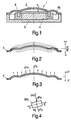
- FIG. 1 shows a simplified cross section of a speaker 1.
- the speaker 1 comprises a membrane 2, a coil 3 attached to said membrane 2, a magnetic system 4 interacting with the coil 3, and a housing 5, which keeps the aforesaid parts together.
- the membrane 2 has a certain thickness d and together with housing 5 forms a back volume Vb.
- Membrane 2 normally also comprises corrugations, which enable its movement, which corrugations are left in this and further drawings for the sake of brevity.
- FIG. 2 now shows the movement of the membrane 2.
- Membrane 2 may move in the direction of movement MOV. Thin lines indicate its lower dead center and its upper dead center. The distance of movement s of the membrane 2 is measured in direction of movement MOV, wherein a positive distance of movement s indicates an upward movement, a negative one a downward movement.
- Figure 3 shows differential operating loads dFo acting on the membrane 2.
- the coil 3 which is not shown, forces the membrane 2 to move up and down. Integration of all differential operating loads dFo results in an overall operating load Fo, which is to be produced by the magnetic force between coil 3 and magnetic system 4. Loads F directed upwards are positive, those directed downwards are negative.
- Figure 4 shows a differential part 2dp of membrane 2 (see also dotted circle in Fig. 3 ).
- a differential mass dm an acceleration -a downwards causes a differential accelerating force dFa to go up:
- ⁇ angular velocity
- f the frequency of the membrane 2
- smax is the maximum amplitude of the membrane 2.
- a differential pressure force dFp is acting on the differential part 2dp, since it is assumed that the membrane 2 is below its idle position in Fig. 4 .
- both, the differential accelerating force dFa and the differential pressure force dFp form the differential operating load dFo.
- the latter one causes the membrane 2 to be bent.
- the elasticity of the membrane defined by the Young's modulus E of the membrane 2, transversal to its extension of thickness d, acts against this bending (see also Eavg in Fig. 7 for the definition of said direction).
- a certain operating load Fo leads to a certain movement of the membrane 2.
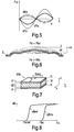
- Figure 5 now shows the distance of movement s of the membrane 2 as well as the differential loads dF acting on the membrane 2 over time. It is assumed that a sinusoidal current flows through the coil 3. Hence the membrane 2 moves sinusoidally as well, visualized by the graph for the distance of movement s (solid thin line).
- the differential accelerating force dFa (dash-and-dot line) is sinusoidal as well, as it is directed opposite to the acceleration a, which is the second derivation of the distance of movement s.
- dFp dashex-and-dot line
- both the differential accelerating force dFa and the differential pressure force dFp forms the differential operating load dFo (solid bold line) as stated before. Since membranes in general are relatively lightweight and sound pressure is relatively high (meaning that the amplitude of the membrane's movement is also high), the differential pressure force dFp is higher than the differential accelerating force dFa. Since both are in phase, the differential operating load dFo shows an in-phase negative sinusoidal graph. The same applies to overall loads, meaning that the differential loads may be integrated over the whole membrane 2 or at least over part of said membrane 2.
- FIG. 6 now shows the membrane 2 in its idle position as well as in its upper dead center (thin dashed line).
- the dome of the membrane 2 which is the part of the membrane 2 inside the coil 3 substantially keeps its shape. At the least it is bent outwards.
- the dome of the membrane 2 snaps inwards due to the so-called buckling and/or crinkling effect (thin solid line).
- a multi-layer membrane for an electroacoustic transducer comprising:
- the critical buckling/crinkling load Fbc depends on a second form factor k2, the thickness d of the membrane, a third form factor x, which is an exponent of the thickness d, and the Young's modulus E of the membrane.
- First form factor k1 (from the formula for the resonant frequency fres), second form factor k2 and third form factor x depend on the geometric shape and dimension of a membrane. Due to the complex forms of the membranes it is more or less impossible to give formulas for the values of the factors k1, k2, and x. They can only be determined by computer simulation of a certain membrane.
- Membrane for an electroacoustic transducer wherein a thickness of said membrane and an average Young's modulus of said membrane, transversal to its extension of thickness, are chosen in such a way that the stiffness of the membrane in its direction of movement is decreased, compared to a reference membrane of the same shape, dimension, and critical load, which decrease causes at least part of the reference membrane made of Polycarbonate to buckle and/or crinkle.
- a thickness of said membrane and an average Young's modulus of said membrane, transversal to its extension of thickness are chosen in such a way that the stiffness of the membrane in its direction of movement is decreased, compared to a reference membrane of the same shape, dimension, and critical load, which decrease causes at least part of the reference membrane made of Polycarbonate to buckle and/or crinkle.
- the only difference here is the way of defining of the technical improvement.
- a preferred membrane is now achieved, when the average Young's modulus is lower and the thickness is higher than those of said reference membrane. In this manner the critical buckling/crinkling load may be increased.
- Thicker membranes are easier to produce than thinner ones. During the ironing process a piece of raw material is stretched to a multiple of its original extension, reducing the thickness to a fraction at the same time. The higher the ratio between original thickness and thickness of the finished membrane, the more critical it is to obtain similar membranes, since the material characteristics vary. Thus it is preferred to have a lower ratio so as to increase the membrane's reproducibility.
- the present invention offers the advantage to have relatively thick membranes at an increased sound quality and/or sound pressure.
- a preferred membrane is further achieved, when the critical buckling/crinkling load is higher than the operating loads of said transducer on said membrane, which are higher than the critical reference buckling/crinkling load of said reference membrane. This condition defines the secure operating area of a transducer, because the operating loads do not exceed the critical buckling/crinkling load.
- Yet another preferred embodiment of the invention is a membrane, wherein the absolute value of the difference of pressure between an environment of said electroacoustic transducer and said back volume of said transducer is higher than 600 Pa (150dB).
- transducers for example a speaker in a mobile device such as a mobile phone, often have very small back volumes due to limited space. This results in a dramatic increase of the difference of pressure between the environment of the transducer and its back volume, which can easily be imagined when looking at the adiabatic gas equation. Therefore the present invention in particular refers to transducers having a relatively small back volume and a relatively high sound pressure (meaning a high amplitude of the membrane).
- a further preferred embodiment of the invention is a membrane, wherein said absolute value is higher than 2000 Pa (160 dB).
- 6000 Pa (170 dB is of advantage.
- Another preferred embodiment of the invention is a membrane, comprising at least two layers of different materials.
- a so-called compound membrane which consists of various layers of different materials.
- Very common are compound membranes having outer layers of relatively hard material with a relatively soft material in-between. Usually they are used because of their good damping characteristics.
- the present invention proposes to use them also to prevent buckling and/or crinkling.
- the membrane comprises two outer first layers made of Polyarylate (PAR) or Polycarbonate (PC) and an inner second layer made of an adhesive on acrylic basis. It has been found out during experiments that this combination of materials notably provide the inventive effect. The object of the invention may therefore be achieved by using common materials.
- PAR Polyarylate
- PC Polycarbonate
- the object of the invention is furthermore achieved by an electroacoustic transducer, comprising an inventive membrane, as well as by a device, comprising an inventive electroacoustic transducer.
- an electroacoustic transducer comprising an inventive membrane
- a device comprising an inventive electroacoustic transducer.
- the invention is related to electroacoustic transducers in general, which means to speakers as well as microphones, even though reference is mostly made to speakers.
- Figure 7 shows how the average Young's modulus of a membrane 2, transversal to its extension of thickness d (here in y-direction) may be calculated.
- the membrane 2 is of the so-called compound type.
- Two first outer layers 11 of a first material enclose a second layer 12 of a second material.
- the first outer layers 11 are made of Polyarylat (PAR) and the inner second layer 12 is made of an adhesive on acrylic basis.
- the first layers 11 have a first thickness d1, the second layer 12 a second thickness d2.
- the first material has a first Young's modulus El
- the second material has a second Young's modulus E2.
- the Figure 7 shows a cuboid, cut out of the membrane 2, with an overall thickness 2 ⁇ d1+d2, a width w and a length 1.
- the average Young's modulus Eavg of a membrane 2, transversal to its extension of thickness d is calculated in the following:
- the relative elongation ⁇ in y-direction is the same for all three layers 11, 12, 11.
- Figure 8 shows the buckling/crinkling amplitude sB plotted against the operating loads Fo. Two graphs are drawn, a first graph sBref for a reference membrane made of Polycarbonate and a second one sBinv for a inventive membrane 2.
- the second graph sBinv has similar characteristics, but is shifted towards higher operating loads Fo, meaning that the critical buckling/crinkling load Fbc is much higher than the critical reference buckling/crinkling load Fbcref.
- the membrane 2 can be operated under higher operating loads Fo, which allows to increase the sound pressure. It should be noted at this point that both membrane 2 and the reference membrane have the same shape, dimension, and stiffness (and therefore the same resonant frequency) in direction of movement MOV.
- the area to the left of the first graph sBref defines the area of prior art transducers which are operated with membranes of known materials.
- the area to the right of the first graph sBref defines the area of the invention.
- In between the first and second graphs sBref and sBinv is the area, wherein an inventive transducer may be operated. If the operating loads Fo exceed the critical buckling/crinkling load Fbc, again there is buckling/crinkling, degrading acoustic performance of the transducer.
Landscapes
- Engineering & Computer Science (AREA)
- Multimedia (AREA)
- Physics & Mathematics (AREA)
- Acoustics & Sound (AREA)
- Signal Processing (AREA)
- Diaphragms For Electromechanical Transducers (AREA)
- Audible-Bandwidth Dynamoelectric Transducers Other Than Pickups (AREA)
Description
- The invention relates to a membrane for an electroacoustic transducer, to an electroacoustic transducer having an inventive membrane, as well as to a device having an inventive transducer.
- The ever increasing requirements on electroacoustic transducers, meaning increased sound pressure and sound quality at a decreased size of said transducers, lead to certain problems, wherein the membrane, which is a very important part, represents one of them. For good sound reproduction, on the one hand, a low resonant frequency of the membrane should be obtained, which means that thin membranes made of soft materials should be chosen. High sound pressures, on the other hand, demand relatively thick and stiff membranes. So there are opposite basic requirements for a membrane, which are to be balanced and which define a limit to what is technically possible. Nowadays transducers using membranes made of common materials such as Polycarbonate (PC), Polyetherimide (PEI), Polyethylenterephthalate (PET), or Polyethylennaphtalate (PEN), have reached this borderline, which is to be broken through.
- To explain the aforesaid problems in more detail, reference is now made to
Figure 1 , which shows a simplified cross section of a speaker 1. The speaker 1 comprises amembrane 2, acoil 3 attached to saidmembrane 2, amagnetic system 4 interacting with thecoil 3, and ahousing 5, which keeps the aforesaid parts together. Themembrane 2 has a certain thickness d and together withhousing 5 forms a back volume Vb.Membrane 2 normally also comprises corrugations, which enable its movement, which corrugations are left in this and further drawings for the sake of brevity. -
Figure 2 now shows the movement of themembrane 2.Membrane 2 may move in the direction of movement MOV. Thin lines indicate its lower dead center and its upper dead center. The distance of movement s of themembrane 2 is measured in direction of movement MOV, wherein a positive distance of movement s indicates an upward movement, a negative one a downward movement. -
Figure 3 shows differential operating loads dFo acting on themembrane 2. Thecoil 3, which is not shown, forces themembrane 2 to move up and down. Integration of all differential operating loads dFo results in an overall operating load Fo, which is to be produced by the magnetic force betweencoil 3 andmagnetic system 4. Loads F directed upwards are positive, those directed downwards are negative. -
Figure 4 shows a differential part 2dp of membrane 2 (see also dotted circle inFig. 3 ). As it has a differential mass dm, an acceleration -a downwards causes a differential accelerating force dFa to go up:
membrane 2 and wherein smax is the maximum amplitude of themembrane 2. At the same time a differential pressure force dFp is acting on the differential part 2dp, since it is assumed that themembrane 2 is below its idle position inFig. 4 . Thus the back volume Vb is compressed, causing a positive pressure force dFp acting perpendicularly on themembrane 2 according to the adiabatic gas equation
membrane 2 moves upwards. The differential pressure force dFp may now be calculated as follows
- Both, the differential accelerating force dFa and the differential pressure force dFp form the differential operating load dFo. The latter one causes the
membrane 2 to be bent. The elasticity of the membrane, defined by the Young's modulus E of themembrane 2, transversal to its extension of thickness d, acts against this bending (see also Eavg inFig. 7 for the definition of said direction). Hence a certain operating load Fo leads to a certain movement of themembrane 2. -
Figure 5 now shows the distance of movement s of themembrane 2 as well as the differential loads dF acting on themembrane 2 over time. It is assumed that a sinusoidal current flows through thecoil 3. Hence themembrane 2 moves sinusoidally as well, visualized by the graph for the distance of movement s (solid thin line). The differential accelerating force dFa (dash-and-dot line) is sinusoidal as well, as it is directed opposite to the acceleration a, which is the second derivation of the distance of movement s. In contrast to that is the differential pressure force dFp (dashed line), which is at its negative maximum in the upper dead center of themembrane 2. Both the differential accelerating force dFa and the differential pressure force dFp forms the differential operating load dFo (solid bold line) as stated before. Since membranes in general are relatively lightweight and sound pressure is relatively high (meaning that the amplitude of the membrane's movement is also high), the differential pressure force dFp is higher than the differential accelerating force dFa. Since both are in phase, the differential operating load dFo shows an in-phase negative sinusoidal graph. The same applies to overall loads, meaning that the differential loads may be integrated over thewhole membrane 2 or at least over part of saidmembrane 2. -
Figure 6 now shows themembrane 2 in its idle position as well as in its upper dead center (thin dashed line). As long as the operating load Fo is below a so-called critical buckling/crinkling load Fbc, the dome of themembrane 2, which is the part of themembrane 2 inside thecoil 3, substantially keeps its shape. At the least it is bent outwards. When the operating load Fo exceeds the critical buckling/crinkling load Fbc, the dome of themembrane 2 snaps inwards due to the so-called buckling and/or crinkling effect (thin solid line). - The same applies to the border area of the
membrane 2 outside thecoil 3 as well. Normally it is bent outwards, but at a certain load it may snap inwards. This effect is quite complex and highly depends on the shape of themembrane 2. A higher dome for instance would buckle much later than a flat one. Corrugations too, which are normally part of a membrane but which were left out for the sake of brevity here, highly influence this buckling and/or crinkling. Thus this effect may also be limited to a relatively small area of themembrane 2, for example if there are sharp edges or intersections, which essentially influence the mechanical behavior of themembrane 2. Because of the complexity of the buckling/crinkling effect, it is only possible to calculate where and when buckling/crinkling occurs by the use of computer simulation using the finite elements method. - In any case the aforesaid buckling and/or crinkling is an unwanted effect because it dramatically draws down the acoustic quality of a transducer as can easily be imagined.
Membrane 2 is to compress the air in front of the transducer in its upper position, whereas it more or less decompresses the air, when themembrane 2 buckles. So the sound wave does not show a sinusoidal graph anymore, although the current in thecoil 3 does. This is unacceptable for present-day requirements. - To explain the balancing problem of sound quality and sound pressure, which was briefly mentioned in the first paragraph of the "background of the invention" in more detail, reference is now made to basic formulas for the resonant frequency and for the stiffness of a membrane (meaning its resistance against movement in direction of movement or its spring constant):

- According to the first formula the resonant frequency fres of a membrane depends on a first form factor k1, the thickness d of the membrane and the Young's modulus E of the membrane. Since there is a tendency to decrease the resonant frequency fres, so as to increase the acoustic performance of a transducer, there is also a tendency to reduce the thickness d of the membranes. This leads to a drawback as the stiffness S of a membrane in its direction of movement is proportional to the square of the resonant frequency.

- It can easily be seen that a reduction of the thickness d and thus a reduction of resonant frequency fres results in a decrease of the stiffness S. A lower stiffness S in turn results in a decreased maximum possible sound pressure and an increased tendency for buckling/crinkling, which is undesired. So one could try to increase the Young's modulus E accordingly. But reaching the same stiffness S (and according to former investigations hence also the same tendency for buckling/crinkling) means also reaching the same resonant frequency fres again, which results in a degraded sound quality. The same applies to one who would decrease Young's modulus E and increase thickness d.
- To illustrate this fact, a simple example is given. To improve sound quality an engineer reduces the thickness s of the membrane by half. Accordingly, the resonant frequency fres is also halved. Looking at the stiffness S he realizes that stiffness S is only one fourth. Hence he chooses a material having a Young's modulus E four times higher to keep the same stiffness S, but evaluating the formula for the resonant frequency fres again, he realizes that the resonant frequency fres which was halved originally is doubled and hence the same as at the start.
- According to the aforesaid formulas there is no material to be expected which would lead to a breakthrough, meaning increasing sound quality (by reducing resonant frequency fres) and increasing sound pressure (by increasing stiffness S) at the same time, even when a harder material is chosen. Therefore, known materials simply have been kept, so that normally Polycarbonate (PC), Polyetherimide (PEI), Polyethylentrephthalate (PET), or Polyethylennaphtalate (PEN) have been used for membranes for example.
- These materials define a technical borderline, because they only allow certain combinations of sound quality and sound pressure. Beyond this borderline buckling and/or crinkling occurs, meaning that the operating load Fo exceeds the critical buckling/crinkling load Fbc. To develop improved transducers this borderline is to be crossed.
- Document HORNUNG M ET AL: "optimization Of Micromachined Ultrasound Transducer By Finite Elemente Simulation", PROCEEDINGS OF THE INTERNATIONAL SOLID-STATE SENSORS AND ACTUATROS CONFERENCE - TRANSDUCERS '95, vol. 2, 25 June 1995 (1995-06-25), pages 620-623, XP010305071, Stockholm, Sweden, 25-29 June 1995) discloses a membrane for an electroacoustic transducer, wherein a thickness of the membrane and an average Young's modulus of the membrane, transversal to its extension of thickness are varied.
- Hence it is an object of this invention to prevent a membrane from buckling and/or crinkling.
- This object is achieved by a multi-layer membrane for an electroacoustic transducer comprising:
- a first outer layer made of Polyarylate or Polycarbonate;
- a second outer layer made of Polyarylate or Polycarbonate: and
- an inner layer located between the first outer layer (11) and the second outer layer made of an adhesive on an acrylic base,
- wherein a thickness of said membrane and an average Young's modulus of said membrane, transversal to its extension of thickness are chosen in such a way that the critical load, which causes at least part of the membrane to buckle and/or crinkle, is increased, compared to a reference membrane made of Polycarbonate of the same shape, dimension transversal to its extension of thickness, and stiffness in its direction of movement.
- Surprisingly, the buckling and/or crinkling effect occurs at different critical buckling/crinkling loads for membranes of the same shape and dimension, but made of different materials, even when the stiffness of the membranes in their direction of movement is identical. This behavior was not to be predicted so that one does not wonder that there was a stagnation in transducer development. What was found out during extensive experiments and computer simulations is the following formula, which show the influence of basic characteristics of a membrane on the critical buckling/crinkling load Fbc.

- The critical buckling/crinkling load Fbc depends on a second form factor k2, the thickness d of the membrane, a third form factor x, which is an exponent of the thickness d, and the Young's modulus E of the membrane. First form factor k1 (from the formula for the resonant frequency fres), second form factor k2 and third form factor x depend on the geometric shape and dimension of a membrane. Due to the complex forms of the membranes it is more or less impossible to give formulas for the values of the factors k1, k2, and x. They can only be determined by computer simulation of a certain membrane.
- What the aforesaid formulae show is the following: Starting with a reference membrane made of Polycarbonate, as it has been commonly used for membranes, the resistance against buckling/crinkling can be improved without decreasing its acoustic performance (meaning keeping the resonant frequency fres of the membrane constant) by increasing the thickness d of the membrane and decreasing its Young's modulus E because of the third form factor x, which is always greater than 2. Hence an increase of the critical buckling/crinkling load Fbc has not necessarily led to an increase of the resonant frequency fres. An increased critical buckling/crinkling load Fbc not only allows higher sound pressures, but also flatter domes of the membrane and hence flatter speakers, because the lower the dome, the higher its tendency to buckle/crinkle.
- Coming back to our engineer who reduces thickness s of the membrane by half, we see the following. Again the resonant frequency fres is halved, and the stiffness S is only one fourth, but the critical buckling/crinkling load Fbc is higher than only one fourth, just by way of example let us say one third. Hence he chooses a material having a Young's modulus E three times higher to keep the same critical buckling/crinkling load Fbc. Evaluating the formula for the resonant frequency fres again, he realizes that the resonant frequency fres, which was halved originally, is increased by the square root of three and hence lower than at the start.
- It should be noted that the invention could also be defined as follows: Membrane for an electroacoustic transducer, wherein a thickness of said membrane and an average Young's modulus of said membrane, transversal to its extension of thickness, are chosen in such a way that the stiffness of the membrane in its direction of movement is decreased, compared to a reference membrane of the same shape, dimension, and critical load, which decrease causes at least part of the reference membrane made of Polycarbonate to buckle and/or crinkle. The only difference here is the way of defining of the technical improvement.
- A preferred membrane is now achieved, when the average Young's modulus is lower and the thickness is higher than those of said reference membrane. In this manner the critical buckling/crinkling load may be increased. Apart from the advantages which may be directly derived from the aforementioned formulas, there is an another advantage. Thicker membranes are easier to produce than thinner ones. During the ironing process a piece of raw material is stretched to a multiple of its original extension, reducing the thickness to a fraction at the same time. The higher the ratio between original thickness and thickness of the finished membrane, the more critical it is to obtain similar membranes, since the material characteristics vary. Thus it is preferred to have a lower ratio so as to increase the membrane's reproducibility. The present invention offers the advantage to have relatively thick membranes at an increased sound quality and/or sound pressure.
- A preferred membrane is further achieved, when the critical buckling/crinkling load is higher than the operating loads of said transducer on said membrane, which are higher than the critical reference buckling/crinkling load of said reference membrane. This condition defines the secure operating area of a transducer, because the operating loads do not exceed the critical buckling/crinkling load.
- It is further advantageous, when said critical buckling/crinkling load of said membrane is 20% lower than that of said reference membrane when defining the invention by means of a variable critical buckling/crinkling load (stiffness constant), and when said stiffness of said membrane is 20% lower than that of said reference membrane when defining the invention by means of variable stiffness (critical buckling/crinkling load constant). In this manner the invention is defined by a certain amount of technical improvement.
- Yet another preferred embodiment of the invention is a membrane, wherein the absolute value of the difference of pressure between an environment of said electroacoustic transducer and said back volume of said transducer is higher than 600 Pa (150dB). Nowadays transducers, for example a speaker in a mobile device such as a mobile phone, often have very small back volumes due to limited space. This results in a dramatic increase of the difference of pressure between the environment of the transducer and its back volume, which can easily be imagined when looking at the adiabatic gas equation. Therefore the present invention in particular refers to transducers having a relatively small back volume and a relatively high sound pressure (meaning a high amplitude of the membrane). A further preferred embodiment of the invention is a membrane, wherein said absolute value is higher than 2000 Pa (160 dB). Finally is of advantage a membrane in which said absolute value is higher than 6000 Pa (170 dB).
- It is also advantageous when a material with a Young's modulus of 2.5 GPa is used instead of Polycarbonate for the reference membrane. Since the Young's modulus of Polycarbonate may vary, a definite value for the reference Young's modulus is defined.
- Another preferred embodiment of the invention is a membrane, comprising at least two layers of different materials. To achieve a reduction of the Young's modulus it is proposed to use a so-called compound membrane, which consists of various layers of different materials. Very common are compound membranes having outer layers of relatively hard material with a relatively soft material in-between. Usually they are used because of their good damping characteristics. The present invention proposes to use them also to prevent buckling and/or crinkling.
- Finally it is also advantageous, when the membrane comprises two outer first layers made of Polyarylate (PAR) or Polycarbonate (PC) and an inner second layer made of an adhesive on acrylic basis. It has been found out during experiments that this combination of materials notably provide the inventive effect. The object of the invention may therefore be achieved by using common materials.
- The object of the invention is furthermore achieved by an electroacoustic transducer, comprising an inventive membrane, as well as by a device, comprising an inventive electroacoustic transducer. Advantages and preferred embodiments stated for the inventive membrane apply to the inventive transducer and the inventive device as well.
- It should be noted that the invention is related to electroacoustic transducers in general, which means to speakers as well as microphones, even though reference is mostly made to speakers.
- The aspects defined above and further aspects of the invention are apparent from the examples of embodiment to be described hereinafter and are explained with reference to these examples of embodiment.
- The invention will be described in more detail hereinafter with reference to examples of embodiment but to which the invention is not limited.
-
Figure 1 shows a simplified cross section of a speaker; -
Figure 2 shows the movement of a speaker's membrane; -
Figure 3 shows differential operating loads acting on a membrane; -
Figure 4 shows an differential part of a membrane; -
Figure 5 shows the distance of movement of a membrane as well as the differential forces acting on it plotted against time; -
Figure 6 shows the buckling/crinkling effect of a membrane. -
Figure 7 shows how the average Young's modulus of a membrane may be calculated; -
Figure 8 shows the buckling/crinkling amplitude over the operating loads. -
Figure 7 shows how the average Young's modulus of amembrane 2, transversal to its extension of thickness d (here in y-direction) may be calculated. Themembrane 2 is of the so-called compound type. Two firstouter layers 11 of a first material enclose asecond layer 12 of a second material. For example the firstouter layers 11 are made of Polyarylat (PAR) and the innersecond layer 12 is made of an adhesive on acrylic basis. - The first layers 11 have a first thickness d1, the second layer 12 a second thickness d2. Moreover, the first material has a first Young's modulus El, the second material a second Young's modulus E2. The
Figure 7 shows a cuboid, cut out of themembrane 2, with anoverall thickness 2·d1+d2, a width w and a length 1. The average Young's modulus Eavg of amembrane 2, transversal to its extension of thickness d is calculated in the following: The relative elongation ε in y-direction is the same for all threelayers first layer 11 may be calculated as
second layer 12 may be calculated as




-
Figure 8 shows the buckling/crinkling amplitude sB plotted against the operating loads Fo. Two graphs are drawn, a first graph sBref for a reference membrane made of Polycarbonate and a second one sBinv for ainventive membrane 2. - Over a wide range there is no buckling or crinkling for the reference membrane (first graph sBref) until the critical reference buckling/crinkling load Fbcref is reached. A further increase of the operating loads Fo results in a dramatic increase of the buckling/crinkling amplitude sB. This critical point is also shown in
Figure 6 , where the snap down of the membrane for Fo > Fbc is shown (for ease of visualization the absolute value of the buckling/crinkling amplitude sB is shown inFigure 8 ). After this snapping the buckling/crinkling amplitude sB is more or less saturated, meaning that a further increase of the operating loads Fo does not result in a substantial increase of the buckling/crinkling amplitude sB. - The second graph sBinv has similar characteristics, but is shifted towards higher operating loads Fo, meaning that the critical buckling/crinkling load Fbc is much higher than the critical reference buckling/crinkling load Fbcref. Hence the
membrane 2 can be operated under higher operating loads Fo, which allows to increase the sound pressure. It should be noted at this point that bothmembrane 2 and the reference membrane have the same shape, dimension, and stiffness (and therefore the same resonant frequency) in direction of movement MOV. - In conclusion it may be observed that the area to the left of the first graph sBref defines the area of prior art transducers which are operated with membranes of known materials. The area to the right of the first graph sBref defines the area of the invention. In between the first and second graphs sBref and sBinv is the area, wherein an inventive transducer may be operated. If the operating loads Fo exceed the critical buckling/crinkling load Fbc, again there is buckling/crinkling, degrading acoustic performance of the transducer.
- Finally, it should be noted that the above-mentioned embodiments illustrate rather than limit the invention, and that those skilled in the art will be capable of designing many alternative embodiments without departing from the scope of the invention as defined by the appended claims. In the claims, any reference signs placed in parentheses shall not be construed as limiting the claims. The word "comprising" and "comprises", and the like, does not exclude the presence of elements or steps other than those listed in any claim or the specification as a whole. The singular reference of an element does not exclude the plural reference of such elements and vice-versa. In a device claim enumerating several means, several of these means may be embodied by one and the same item of hardware. The mere fact that certain measures are recited in mutually different dependent claims does not indicate that a combination of these measures cannot be used to advantage.
Claims (11)
- A multi-layer membrane (2) for an electroacoustic transducer (1) comprising:a first outer layer (11) made of Polyarylate or Polycarbonate;a second outer layer (11) made of Polyarylate or Polycarbonate; andan inner layer (12) located between the first outer layer (11) and the second outer layer (11) made of an adhesive on an acrylic base,wherein a thickness (d) of said membrane (2) and an average Young's modulus (Eavg) of said membrane (2), transversal to its extension of thickness (d) are chosen in such a way that the critical load (Fbc), which causes at least part of the membrane (1) to buckle and/or crinkle, is increased, compared to a reference membrane made of Polycarbonate of the same shape, dimension transversal to its extension of thickness (d), and stiffness in its direction of movement (MOV).
- The multi-layer membrane (2) according to claim 1, wherein the average Young's modulus (Eavg) is lower and the thickness (d) is higher than those of said reference membrane.
- The multi-layer membrane (2) according to claim 1, wherein the critical buckling/crinkling load (Fbc) is higher than the operating loads (Fo) of said transducer (1) on said membrane (2), which are higher than the critical reference buckling/ crinkling load (Fbcref) of said reference membrane.
- The multi-layer membrane (2) according to claim 1, wherein the absolute value of the difference of pressure between an environment of said electroacoustic transducer (1) and a back volume (Vb) of said transducer (1) is higher than 600 Pa.
- The multi-layer membrane (2) according to claim 1, wherein a material with a Young's modulus of 2.5 GPa is used instead of Polycarbonate for the reference membrane.
- The multi-layer membrane (2) according to claim 3, wherein the critical load of the multi-layer membrane (2) is 20% lower than the critical load of the reference membrane.
- The multi-layer membrane (2) according to claim 3, wherein the stiffness of the multi-layer membrane (2) is 20% lower than the stiffness of the reference membrane.
- The multi-layer membrane (2) according to claim 4, wherein the absolute value of the difference of pressure between the environment of the electroacoustic transducer (1) and the back volume (Vb) of the transducer (1) is higher than 2000 Pa.
- The multi-layer membrane (2) according to claim 8, wherein the absolute value of the difference of pressure between the environment of the electroacoustic transducer (1) and the back volume (Vb) of the transducer (1) is higher than 6000 Pa.
- Electroacoustic transducer, comprising a multi-layer membrane according to any one of the claims 1-9.
- Device comprising an electroacoustic transducer according to claim 10.
Priority Applications (1)
| Application Number | Priority Date | Filing Date | Title |
|---|---|---|---|
| EP06710992.6A EP1859649B1 (en) | 2005-03-10 | 2006-03-01 | Membrane with high resistance against buckling and/or crinkling |
Applications Claiming Priority (3)
| Application Number | Priority Date | Filing Date | Title |
|---|---|---|---|
| EP05101861 | 2005-03-10 | ||
| PCT/IB2006/050633 WO2006095280A1 (en) | 2005-03-10 | 2006-03-01 | Membrane with high resistance against buckling and/or crinkling |
| EP06710992.6A EP1859649B1 (en) | 2005-03-10 | 2006-03-01 | Membrane with high resistance against buckling and/or crinkling |
Publications (2)
| Publication Number | Publication Date |
|---|---|
| EP1859649A1 EP1859649A1 (en) | 2007-11-28 |
| EP1859649B1 true EP1859649B1 (en) | 2016-05-18 |
Family
ID=36390145
Family Applications (1)
| Application Number | Title | Priority Date | Filing Date |
|---|---|---|---|
| EP06710992.6A Expired - Lifetime EP1859649B1 (en) | 2005-03-10 | 2006-03-01 | Membrane with high resistance against buckling and/or crinkling |
Country Status (6)
| Country | Link |
|---|---|
| US (1) | US7644801B2 (en) |
| EP (1) | EP1859649B1 (en) |
| JP (1) | JP2008533790A (en) |
| KR (1) | KR101199689B1 (en) |
| CN (1) | CN101147422B (en) |
| WO (1) | WO2006095280A1 (en) |
Families Citing this family (9)
| Publication number | Priority date | Publication date | Assignee | Title |
|---|---|---|---|---|
| EP2268058B1 (en) * | 2009-06-26 | 2019-10-30 | SSI New Material (Zhenjiang) Co., Ltd. | Diaphragm for a micro loudspeaker |
| CN102065355A (en) * | 2010-05-04 | 2011-05-18 | 瑞声声学科技(深圳)有限公司 | Vibrating membrane and miniature acoustic generator comprising same |
| US20120308037A1 (en) * | 2011-06-03 | 2012-12-06 | Hung-Jen Chen | Microelectromechanical microphone chip having stereoscopic diaphragm structure and fabrication method thereof |
| US11001494B2 (en) | 2011-06-23 | 2021-05-11 | Duality Reality Energy, LLC | Multi-zone microstructure spring |
| US9085454B2 (en) | 2011-07-05 | 2015-07-21 | Duality Reality Energy, LLC | Reduced stiffness micro-mechanical structure |
| US9076961B2 (en) | 2012-01-31 | 2015-07-07 | Duality Reality Energy, LLC | Energy harvesting with a micro-electro-machanical system (MEMS) |
| DE102012208477A1 (en) | 2012-05-21 | 2013-11-21 | Tesa Se | Asymmetric multilayer membrane for electroacoustic transducers |
| CN202873037U (en) * | 2012-09-26 | 2013-04-10 | 瑞声光电科技(常州)有限公司 | Composite diaphragm and loudspeaker applying the same |
| US9113250B2 (en) * | 2013-05-29 | 2015-08-18 | Tang Band Industries Co., Ltd. | Speaker with diaphragm arrangement |
Family Cites Families (20)
| Publication number | Priority date | Publication date | Assignee | Title |
|---|---|---|---|---|
| DE2500397C2 (en) * | 1975-01-07 | 1986-05-28 | Schorlemer, Frhr. von, Reinfried, Dipl.-Phys., 3500 Kassel | Membrane for an electroacoustic transducer system and an electroacoustic transducer system equipped with it |
| CA1098774A (en) * | 1976-05-17 | 1981-04-07 | Hirotoshi Niguchi | Acoustic diaphragm with polyurethane elastomer coating |
| GB2134748B (en) * | 1983-01-17 | 1986-06-25 | Victor Company Of Japan | Loudspeaker diaphragm |
| EP0297572B1 (en) * | 1987-07-03 | 1991-05-02 | EWD Electronic-Werke Deutschland GmbH | Membrane for loudspeaker |
| US5259036A (en) * | 1991-07-22 | 1993-11-02 | Shure Brothers, Inc. | Diaphragm for dynamic microphones and methods of manufacturing the same |
| CN2119059U (en) * | 1991-12-06 | 1992-10-14 | 天津市电声器材厂 | Speaker mounted to car |
| CN1122436C (en) * | 1994-11-30 | 2003-09-24 | 先锋电子股份有限公司 | Loudspeaker vibrating diaphragm and methods for its production |
| JP3337631B2 (en) * | 1997-11-10 | 2002-10-21 | パイオニア株式会社 | Dome speaker and manufacturing method thereof |
| CN1121809C (en) * | 1999-04-09 | 2003-09-17 | 张凡 | Loudspeaker |
| US6390232B1 (en) * | 1999-10-29 | 2002-05-21 | Communications Products Corporation | Speaker cone assembly |
| JP2002152885A (en) * | 2000-11-14 | 2002-05-24 | Sony Corp | Speaker device |
| US6480563B2 (en) * | 2000-12-19 | 2002-11-12 | Ge Medical Systems Global Technology Co., Llc | System and method of aligning scintillator crystalline structures for computed tomography imaging |
| WO2002093972A2 (en) * | 2001-05-11 | 2002-11-21 | New Transducers Limited | Acoustic member for a loudspeaker comprising a component having a selected frequency dependence and method of making same |
| US7268190B2 (en) * | 2001-08-03 | 2007-09-11 | Toray Industries, Inc. | Resin composition comprising polylactic acid and polyacetal and a molded article, film, and fiber each comprising the same |
| WO2004047487A1 (en) * | 2002-11-21 | 2004-06-03 | Koninklijke Philips Electronics N.V. | Electroacoustic transducer comprising a membrane with a middle area comprising stiffening grooves |
| EP1668955A4 (en) * | 2003-09-08 | 2007-10-31 | John M Norton | Audio loudspeaker |
| CN101002502B (en) * | 2004-04-29 | 2011-07-20 | Nxp股份有限公司 | Diaphragm for a loudspeaker with a moving coil |
| JP2006295245A (en) * | 2005-04-05 | 2006-10-26 | Sony Corp | Acoustic diaphragm |
| JP4049179B2 (en) * | 2005-05-25 | 2008-02-20 | オンキヨー株式会社 | Speaker diaphragm and speaker structure |
| WO2007015518A1 (en) * | 2005-08-02 | 2007-02-08 | Teijin Fibers Limited | Speaker formed with screen as a unitary block |
-
2006
- 2006-03-01 EP EP06710992.6A patent/EP1859649B1/en not_active Expired - Lifetime
- 2006-03-01 US US11/908,288 patent/US7644801B2/en active Active
- 2006-03-01 JP JP2008500299A patent/JP2008533790A/en not_active Withdrawn
- 2006-03-01 WO PCT/IB2006/050633 patent/WO2006095280A1/en not_active Ceased
- 2006-03-01 CN CN2006800076201A patent/CN101147422B/en not_active Expired - Fee Related
- 2006-03-01 KR KR1020077023010A patent/KR101199689B1/en not_active Expired - Fee Related
Also Published As
| Publication number | Publication date |
|---|---|
| JP2008533790A (en) | 2008-08-21 |
| US7644801B2 (en) | 2010-01-12 |
| KR101199689B1 (en) | 2012-11-08 |
| US20080202845A1 (en) | 2008-08-28 |
| WO2006095280A1 (en) | 2006-09-14 |
| KR20070118627A (en) | 2007-12-17 |
| CN101147422B (en) | 2012-11-21 |
| EP1859649A1 (en) | 2007-11-28 |
| CN101147422A (en) | 2008-03-19 |
Similar Documents
| Publication | Publication Date | Title |
|---|---|---|
| CN215268715U (en) | MEMS piezoelectric actuator and loudspeaker thereof | |
| CN205051859U (en) | Acoustic transducer and film that is used for acoustic transducer | |
| TW573438B (en) | Flat panel sound radiator with supported exciter and compliant surround | |
| US8411894B2 (en) | Transducer with deformable corner | |
| US20040037447A1 (en) | Rectangular panel-form loudspeaker and its radiating panel | |
| US7644801B2 (en) | Membrane with a high resistance against buckling and/or crinkling | |
| CN215773557U (en) | MEMS piezoelectric speaker | |
| US9602899B2 (en) | Speaker and its production method | |
| KR20190130649A (en) | Piezoelectric acoustic components | |
| US8437496B2 (en) | Membrane for an acoustic device and acoustic device | |
| CN101310561B (en) | Asymmetrical moving systems for a piezoelectric speaker and asymmetrical speaker | |
| US9674594B2 (en) | Speaker | |
| US20230152411A1 (en) | Directional acoustic sensor | |
| JP2009204836A (en) | Sound absorption structure, sound absorption structure group, sound box, method of adjusting sound structure and noise reduction method | |
| CN112655223A (en) | Product with integrally formed vibration panel speaker | |
| Kim et al. | Zero Poisson's ratio metamaterial and meander-inspired diaphragms for enhancing low-frequency performance in flat-panel loudspeaker | |
| JP7703531B2 (en) | Acoustic transducer with drop ring connected at a resonant node | |
| JP4697007B2 (en) | Electrostatic speaker | |
| Mendoza-López et al. | Characterization and modelling of circular piezoelectric micro speakers for audio acoustic actuation | |
| TWM651929U (en) | Flat diaphragm device | |
| TWI269604B (en) | Diaphragm for micro-electroacoustic device | |
| US20180192205A1 (en) | Lateral mode capacitive microphone | |
| WO2021236063A1 (en) | Actuator module with spring damping layer | |
| Nomoto et al. | Improvement in the Acoustic Characteristics of the Micro Speaker by Changing Thickness and Foaming Ratio of the Diaphragm | |
| Duclos et al. | Study of a dome shaped PVDF loudspeaker |
Legal Events
| Date | Code | Title | Description |
|---|---|---|---|
| PUAI | Public reference made under article 153(3) epc to a published international application that has entered the european phase |
Free format text: ORIGINAL CODE: 0009012 |
|
| 17P | Request for examination filed |
Effective date: 20071010 |
|
| AK | Designated contracting states |
Kind code of ref document: A1 Designated state(s): AT BE BG CH CY CZ DE DK EE ES FI FR GB GR HU IE IS IT LI LT LU LV MC NL PL PT RO SE SI SK TR |
|
| AX | Request for extension of the european patent |
Extension state: AL BA HR MK YU |
|
| 17Q | First examination report despatched |
Effective date: 20080704 |
|
| RAP1 | Party data changed (applicant data changed or rights of an application transferred) |
Owner name: KNOWLES ELECTRONICS ASIA PTE. LTD. |
|
| GRAP | Despatch of communication of intention to grant a patent |
Free format text: ORIGINAL CODE: EPIDOSNIGR1 |
|
| INTG | Intention to grant announced |
Effective date: 20160205 |
|
| GRAS | Grant fee paid |
Free format text: ORIGINAL CODE: EPIDOSNIGR3 |
|
| GRAA | (expected) grant |
Free format text: ORIGINAL CODE: 0009210 |
|
| AK | Designated contracting states |
Kind code of ref document: B1 Designated state(s): AT BE BG CH CY CZ DE DK EE ES FI FR GB GR HU IE IS IT LI LT LU LV MC NL PL PT RO SE SI SK TR |
|
| AX | Request for extension of the european patent |
Extension state: AL BA HR MK YU |
|
| RAP1 | Party data changed (applicant data changed or rights of an application transferred) |
Owner name: KNOWLES IPC (M) SDN BHD |
|
| REG | Reference to a national code |
Ref country code: GB Ref legal event code: FG4D |
|
| REG | Reference to a national code |
Ref country code: DE Ref legal event code: R081 Ref document number: 602006049116 Country of ref document: DE Owner name: SOUND SOLUTIONS INTERNATIONAL CO., LTD., CN Free format text: FORMER OWNER: NXP B.V., EINDHOVEN, NL |
|
| REG | Reference to a national code |
Ref country code: CH Ref legal event code: EP |
|
| REG | Reference to a national code |
Ref country code: IE Ref legal event code: FG4D Ref country code: AT Ref legal event code: REF Ref document number: 801339 Country of ref document: AT Kind code of ref document: T Effective date: 20160615 |
|
| REG | Reference to a national code |
Ref country code: DE Ref legal event code: R096 Ref document number: 602006049116 Country of ref document: DE |
|
| REG | Reference to a national code |
Ref country code: NL Ref legal event code: MP Effective date: 20160518 |
|
| REG | Reference to a national code |
Ref country code: LT Ref legal event code: MG4D |
|
| REG | Reference to a national code |
Ref country code: DE Ref legal event code: R082 Ref document number: 602006049116 Country of ref document: DE Representative=s name: BOSCH JEHLE PATENTANWALTSGESELLSCHAFT MBH, DE Ref country code: DE Ref legal event code: R081 Ref document number: 602006049116 Country of ref document: DE Owner name: SOUND SOLUTIONS INTERNATIONAL CO., LTD., CN Free format text: FORMER OWNER: KNOWLES IPC (M) SDN BHD, PULAU PINANG, MY Ref country code: DE Ref legal event code: R082 Ref document number: 602006049116 Country of ref document: DE Representative=s name: ANWAELTE BURGER UND PARTNER RECHTSANWALTSKANZL, AT Ref country code: DE Ref legal event code: R082 Ref document number: 602006049116 Country of ref document: DE Representative=s name: ABP BURGER RECHTSANWALTSGESELLSCHAFT MBH, DE |
|
| PG25 | Lapsed in a contracting state [announced via postgrant information from national office to epo] |
Ref country code: FI Free format text: LAPSE BECAUSE OF FAILURE TO SUBMIT A TRANSLATION OF THE DESCRIPTION OR TO PAY THE FEE WITHIN THE PRESCRIBED TIME-LIMIT Effective date: 20160518 Ref country code: LT Free format text: LAPSE BECAUSE OF FAILURE TO SUBMIT A TRANSLATION OF THE DESCRIPTION OR TO PAY THE FEE WITHIN THE PRESCRIBED TIME-LIMIT Effective date: 20160518 Ref country code: NL Free format text: LAPSE BECAUSE OF FAILURE TO SUBMIT A TRANSLATION OF THE DESCRIPTION OR TO PAY THE FEE WITHIN THE PRESCRIBED TIME-LIMIT Effective date: 20160518 |
|
| REG | Reference to a national code |
Ref country code: AT Ref legal event code: MK05 Ref document number: 801339 Country of ref document: AT Kind code of ref document: T Effective date: 20160518 |
|
| PG25 | Lapsed in a contracting state [announced via postgrant information from national office to epo] |
Ref country code: LV Free format text: LAPSE BECAUSE OF FAILURE TO SUBMIT A TRANSLATION OF THE DESCRIPTION OR TO PAY THE FEE WITHIN THE PRESCRIBED TIME-LIMIT Effective date: 20160518 Ref country code: GR Free format text: LAPSE BECAUSE OF FAILURE TO SUBMIT A TRANSLATION OF THE DESCRIPTION OR TO PAY THE FEE WITHIN THE PRESCRIBED TIME-LIMIT Effective date: 20160819 Ref country code: SE Free format text: LAPSE BECAUSE OF FAILURE TO SUBMIT A TRANSLATION OF THE DESCRIPTION OR TO PAY THE FEE WITHIN THE PRESCRIBED TIME-LIMIT Effective date: 20160518 Ref country code: PT Free format text: LAPSE BECAUSE OF FAILURE TO SUBMIT A TRANSLATION OF THE DESCRIPTION OR TO PAY THE FEE WITHIN THE PRESCRIBED TIME-LIMIT Effective date: 20160919 Ref country code: ES Free format text: LAPSE BECAUSE OF FAILURE TO SUBMIT A TRANSLATION OF THE DESCRIPTION OR TO PAY THE FEE WITHIN THE PRESCRIBED TIME-LIMIT Effective date: 20160518 |
|
| PG25 | Lapsed in a contracting state [announced via postgrant information from national office to epo] |
Ref country code: IT Free format text: LAPSE BECAUSE OF FAILURE TO SUBMIT A TRANSLATION OF THE DESCRIPTION OR TO PAY THE FEE WITHIN THE PRESCRIBED TIME-LIMIT Effective date: 20160518 |
|
| PG25 | Lapsed in a contracting state [announced via postgrant information from national office to epo] |
Ref country code: SK Free format text: LAPSE BECAUSE OF FAILURE TO SUBMIT A TRANSLATION OF THE DESCRIPTION OR TO PAY THE FEE WITHIN THE PRESCRIBED TIME-LIMIT Effective date: 20160518 Ref country code: DK Free format text: LAPSE BECAUSE OF FAILURE TO SUBMIT A TRANSLATION OF THE DESCRIPTION OR TO PAY THE FEE WITHIN THE PRESCRIBED TIME-LIMIT Effective date: 20160518 Ref country code: EE Free format text: LAPSE BECAUSE OF FAILURE TO SUBMIT A TRANSLATION OF THE DESCRIPTION OR TO PAY THE FEE WITHIN THE PRESCRIBED TIME-LIMIT Effective date: 20160518 Ref country code: RO Free format text: LAPSE BECAUSE OF FAILURE TO SUBMIT A TRANSLATION OF THE DESCRIPTION OR TO PAY THE FEE WITHIN THE PRESCRIBED TIME-LIMIT Effective date: 20160518 Ref country code: CZ Free format text: LAPSE BECAUSE OF FAILURE TO SUBMIT A TRANSLATION OF THE DESCRIPTION OR TO PAY THE FEE WITHIN THE PRESCRIBED TIME-LIMIT Effective date: 20160518 |
|
| REG | Reference to a national code |
Ref country code: DE Ref legal event code: R097 Ref document number: 602006049116 Country of ref document: DE |
|
| PG25 | Lapsed in a contracting state [announced via postgrant information from national office to epo] |
Ref country code: PL Free format text: LAPSE BECAUSE OF FAILURE TO SUBMIT A TRANSLATION OF THE DESCRIPTION OR TO PAY THE FEE WITHIN THE PRESCRIBED TIME-LIMIT Effective date: 20160518 Ref country code: BE Free format text: LAPSE BECAUSE OF FAILURE TO SUBMIT A TRANSLATION OF THE DESCRIPTION OR TO PAY THE FEE WITHIN THE PRESCRIBED TIME-LIMIT Effective date: 20160518 Ref country code: AT Free format text: LAPSE BECAUSE OF FAILURE TO SUBMIT A TRANSLATION OF THE DESCRIPTION OR TO PAY THE FEE WITHIN THE PRESCRIBED TIME-LIMIT Effective date: 20160518 |
|
| REG | Reference to a national code |
Ref country code: DE Ref legal event code: R082 Ref document number: 602006049116 Country of ref document: DE Representative=s name: ANWAELTE BURGER UND PARTNER RECHTSANWALTSKANZL, AT Ref country code: DE Ref legal event code: R082 Ref document number: 602006049116 Country of ref document: DE Representative=s name: ABP BURGER RECHTSANWALTSGESELLSCHAFT MBH, DE |
|
| PLBE | No opposition filed within time limit |
Free format text: ORIGINAL CODE: 0009261 |
|
| STAA | Information on the status of an ep patent application or granted ep patent |
Free format text: STATUS: NO OPPOSITION FILED WITHIN TIME LIMIT |
|
| 26N | No opposition filed |
Effective date: 20170221 |
|
| PGFP | Annual fee paid to national office [announced via postgrant information from national office to epo] |
Ref country code: DE Payment date: 20170221 Year of fee payment: 12 |
|
| PG25 | Lapsed in a contracting state [announced via postgrant information from national office to epo] |
Ref country code: SI Free format text: LAPSE BECAUSE OF FAILURE TO SUBMIT A TRANSLATION OF THE DESCRIPTION OR TO PAY THE FEE WITHIN THE PRESCRIBED TIME-LIMIT Effective date: 20160518 |
|
| REG | Reference to a national code |
Ref country code: CH Ref legal event code: PL |
|
| GBPC | Gb: european patent ceased through non-payment of renewal fee |
Effective date: 20170301 |
|
| PG25 | Lapsed in a contracting state [announced via postgrant information from national office to epo] |
Ref country code: MC Free format text: LAPSE BECAUSE OF FAILURE TO SUBMIT A TRANSLATION OF THE DESCRIPTION OR TO PAY THE FEE WITHIN THE PRESCRIBED TIME-LIMIT Effective date: 20160518 |
|
| REG | Reference to a national code |
Ref country code: IE Ref legal event code: MM4A |
|
| REG | Reference to a national code |
Ref country code: FR Ref legal event code: ST Effective date: 20171130 |
|
| PG25 | Lapsed in a contracting state [announced via postgrant information from national office to epo] |
Ref country code: FR Free format text: LAPSE BECAUSE OF NON-PAYMENT OF DUE FEES Effective date: 20170331 Ref country code: LU Free format text: LAPSE BECAUSE OF NON-PAYMENT OF DUE FEES Effective date: 20170301 |
|
| PG25 | Lapsed in a contracting state [announced via postgrant information from national office to epo] |
Ref country code: LI Free format text: LAPSE BECAUSE OF NON-PAYMENT OF DUE FEES Effective date: 20170331 Ref country code: IE Free format text: LAPSE BECAUSE OF NON-PAYMENT OF DUE FEES Effective date: 20170301 Ref country code: GB Free format text: LAPSE BECAUSE OF NON-PAYMENT OF DUE FEES Effective date: 20170301 Ref country code: CH Free format text: LAPSE BECAUSE OF NON-PAYMENT OF DUE FEES Effective date: 20170331 |
|
| REG | Reference to a national code |
Ref country code: DE Ref legal event code: R082 Ref document number: 602006049116 Country of ref document: DE Representative=s name: ABP BURGER RECHTSANWALTSGESELLSCHAFT MBH, DE |
|
| REG | Reference to a national code |
Ref country code: DE Ref legal event code: R119 Ref document number: 602006049116 Country of ref document: DE |
|
| PG25 | Lapsed in a contracting state [announced via postgrant information from national office to epo] |
Ref country code: DE Free format text: LAPSE BECAUSE OF NON-PAYMENT OF DUE FEES Effective date: 20181002 |
|
| PG25 | Lapsed in a contracting state [announced via postgrant information from national office to epo] |
Ref country code: HU Free format text: LAPSE BECAUSE OF FAILURE TO SUBMIT A TRANSLATION OF THE DESCRIPTION OR TO PAY THE FEE WITHIN THE PRESCRIBED TIME-LIMIT; INVALID AB INITIO Effective date: 20060301 |
|
| PG25 | Lapsed in a contracting state [announced via postgrant information from national office to epo] |
Ref country code: BG Free format text: LAPSE BECAUSE OF FAILURE TO SUBMIT A TRANSLATION OF THE DESCRIPTION OR TO PAY THE FEE WITHIN THE PRESCRIBED TIME-LIMIT Effective date: 20160518 |
|
| PG25 | Lapsed in a contracting state [announced via postgrant information from national office to epo] |
Ref country code: CY Free format text: LAPSE BECAUSE OF NON-PAYMENT OF DUE FEES Effective date: 20160518 |
|
| PG25 | Lapsed in a contracting state [announced via postgrant information from national office to epo] |
Ref country code: TR Free format text: LAPSE BECAUSE OF FAILURE TO SUBMIT A TRANSLATION OF THE DESCRIPTION OR TO PAY THE FEE WITHIN THE PRESCRIBED TIME-LIMIT Effective date: 20160518 |
|
| PG25 | Lapsed in a contracting state [announced via postgrant information from national office to epo] |
Ref country code: IS Free format text: LAPSE BECAUSE OF FAILURE TO SUBMIT A TRANSLATION OF THE DESCRIPTION OR TO PAY THE FEE WITHIN THE PRESCRIBED TIME-LIMIT Effective date: 20160918 |