EP1858460B1 - Device and method for aligning an eye with a surgical laser - Google Patents
Device and method for aligning an eye with a surgical laser Download PDFInfo
- Publication number
- EP1858460B1 EP1858460B1 EP06710216A EP06710216A EP1858460B1 EP 1858460 B1 EP1858460 B1 EP 1858460B1 EP 06710216 A EP06710216 A EP 06710216A EP 06710216 A EP06710216 A EP 06710216A EP 1858460 B1 EP1858460 B1 EP 1858460B1
- Authority
- EP
- European Patent Office
- Prior art keywords
- eye
- laser system
- recited
- spatial position
- laser
- Prior art date
- Legal status (The legal status is an assumption and is not a legal conclusion. Google has not performed a legal analysis and makes no representation as to the accuracy of the status listed.)
- Expired - Lifetime
Links
Images
Classifications
-
- A—HUMAN NECESSITIES
- A61—MEDICAL OR VETERINARY SCIENCE; HYGIENE
- A61F—FILTERS IMPLANTABLE INTO BLOOD VESSELS; PROSTHESES; DEVICES PROVIDING PATENCY TO, OR PREVENTING COLLAPSING OF, TUBULAR STRUCTURES OF THE BODY, e.g. STENTS; ORTHOPAEDIC, NURSING OR CONTRACEPTIVE DEVICES; FOMENTATION; TREATMENT OR PROTECTION OF EYES OR EARS; BANDAGES, DRESSINGS OR ABSORBENT PADS; FIRST-AID KITS
- A61F9/00—Methods or devices for treatment of the eyes; Devices for putting in contact-lenses; Devices to correct squinting; Apparatus to guide the blind; Protective devices for the eyes, carried on the body or in the hand
- A61F9/007—Methods or devices for eye surgery
- A61F9/008—Methods or devices for eye surgery using laser
- A61F9/009—Auxiliary devices making contact with the eyeball and coupling in laser light, e.g. goniolenses
-
- A—HUMAN NECESSITIES
- A61—MEDICAL OR VETERINARY SCIENCE; HYGIENE
- A61F—FILTERS IMPLANTABLE INTO BLOOD VESSELS; PROSTHESES; DEVICES PROVIDING PATENCY TO, OR PREVENTING COLLAPSING OF, TUBULAR STRUCTURES OF THE BODY, e.g. STENTS; ORTHOPAEDIC, NURSING OR CONTRACEPTIVE DEVICES; FOMENTATION; TREATMENT OR PROTECTION OF EYES OR EARS; BANDAGES, DRESSINGS OR ABSORBENT PADS; FIRST-AID KITS
- A61F9/00—Methods or devices for treatment of the eyes; Devices for putting in contact-lenses; Devices to correct squinting; Apparatus to guide the blind; Protective devices for the eyes, carried on the body or in the hand
- A61F9/007—Methods or devices for eye surgery
- A61F9/008—Methods or devices for eye surgery using laser
-
- A—HUMAN NECESSITIES
- A61—MEDICAL OR VETERINARY SCIENCE; HYGIENE
- A61B—DIAGNOSIS; SURGERY; IDENTIFICATION
- A61B17/00—Surgical instruments, devices or methods
- A61B17/30—Surgical pincettes, i.e. surgical tweezers without pivotal connections
- A61B2017/306—Surgical pincettes, i.e. surgical tweezers without pivotal connections holding by means of suction
Definitions
- the present invention pertains generally to devices and methods for performing ocular laser surgery. More particularly, the present invention pertains to devices for positioning the eye of a patient for laser surgery.
- the present invention is useful as a device for establishing a contact alignment between a patient's eye and a laser system to facilitate the engagement of the eye with the laser system prior to a refractive laser surgery procedure.
- Surgical lasers are now commonly used in a variety of ophthalmic applications, including the diagnosis and treatment of ocular diseases, as well as the diagnosis and correction of optical deficiencies.
- corneal reshaping procedures using lasers such as the well known LASIK procedure, are now widely available.
- the surgical laser is chosen as the tool of choice because of the ability of the laser to be accurately focused on extremely small amounts of ocular tissue.
- the ability of the laser to be guided to prescribed locations within the eye with precision and reliability has enabled a whole new class of ophthalmic procedures that require nothing short of pinpoint accuracy.
- movements of the eye relative to the laser source can undermine the accuracy of the laser and reduce the efficacy of the laser procedure.
- movements of the eye can be classified broadly into two groups, namely, voluntary movements and involuntary movements.
- Voluntary movements can often be almost completely eliminated in most patients by instructing the patient to concentrate (i.e. fixate) on a target such as a small light source.
- involuntary eye movements cannot be remedied by instruction, and as a consequence, they must be somehow controlled. Included in the involuntary eye movements are movements due to the patient's pulse, movements due to the patient breathing, and psychotic eye movements which can occur, for example, when a patient is startled.
- eye stabilization systems can be used to effectively eliminate eye movements, and are generally more reliable and less complicated than eye tracking systems.
- some eye stabilization systems can be used to establish a desirable alignment between the eye and the laser source.
- the eye stabilization element can be attached to the laser system to establish and maintain an optimal (and known) optical path length between the eye and laser system.
- eye stabilization devices typically apply a mechanical pressure to the eye for the purpose of restraining the eye.
- this pressure is applied to the surface of the eye (i.e. the sclera, limbus or cornea).
- large pressures applied to the eye are often uncomfortable to the patient and can result in post-operative pain and scarring.
- the pressure can cause damage to the eye by increasing the intra-ocular pressure of the eye to dangerous levels.
- a stabilizing element is first attached to the eye and thereafter the stabilizing element is aligned with and attached to a coupler or adapter on the laser source.
- the pressures exerted on the eye during both stabilization and coupling to the laser source must be considered.
- an eye stabilizing and alignment device must also be positioned such that it does not interfere with the laser procedure. Specifically, this implies that opaque portions of the device do not lie along the laser delivery beam path.
- an objective of the present invention to provide a device and method for aligning a patient's eye relative to a laser system to facilitate an engagement between the eye and laser system.
- Another object of the present invention is to provide an automated device for aligning a patient's eye relative to a laser system which does not rely exclusively on human eye hand coordination.
- Yet another object of the present invention is to provide a device and method for aligning and engaging a patient's eye with a laser system without damaging the eye.
- Still another object of the present invention is to provide a device and method for aligning a patient's eye relative to a laser system that is easy to use, relatively simple to manufacture, and comparatively cost effective.
- the present invention is directed to a device for establishing a desired contact alignment between a patient's eye and a laser system. Once properly aligned, the eye can be safely engaged with the laser system to hold the eye stationary relative to the laser system. This fixed arrangement then allows a surgical beam to be accurately delivered from a source and focused to a selected ocular location.
- a platform is provided for supporting the patient during a surgical procedure. Further, the platform is moveable relative to a laser system. Typically, the platform is configured for independent movement along each of three mutually orthogonal axes (e.g. x, y and z axes), and is moveable in response to a control signal from a system controller.
- the laser system can be mounted on the moveable platform, and the combination of platform and laser system can be reconfigured to control movement of the laser system relative to the patient's eye.
- the device includes a detector and, preferably, an illumination system also.
- the illumination system is positioned and configured to directly illuminate the eye. Reflections from an anatomical feature of the eye are then imaged using a detector and this image, which is indicative of the spatial position of the eye, is transmitted to the system controller.
- a marker can be mounted on the laser system to provide an indication of the laser system's position. Alternatively, a component of the laser system can be used for this purpose. In either case, the marker (or component) is then imaged using the detector. Then, along with the reflections from the eye, the marker (component) image is transmitted to the system controller.
- images of the respective spatial positions of the eye and the laser system are processed to determine a measured alignment of the eye relative to the laser system.
- This measured alignment is then compared to the desired alignment to determine an alignment difference.
- An error signal is then generated that is indicative of the alignment difference.
- the error signal from the system controller is used to incrementally move the platform in an appropriate direction.
- the platform can be a motorized chair having a plurality of individually controllable stepper motors that are selectively energized in response to the error signal.
- a second image can be evaluated. This second image, which includes the marker and reflections from the eye, is detected and used to determine a more refined second alignment difference.
- This second alignment difference is used by the system controller to generate a second error signal and cause a second chair movement. The process is then repeated, as many times as necessary, until the desired alignment between the eye and laser system is achieved (i.e. the alignment difference is zero).
- the alignment device is used to align an eye stabilizing element (e.g. contact lens, suction ring, etc.) with the eye to facilitate an engagement between the eye and the eye stabilizing element.
- an eye stabilizing element e.g. contact lens, suction ring, etc.
- the eye stabilizing element is first fixedly attached to the laser system. Once the eye stabilizing element is aligned with the eye as described above, the eye stabilizing element is advanced toward the eye to contact and engage an anterior surface of the eye.
- the eye stabilizing element can contact and engage the cornea, limbus, sclera and combinations thereof.
- the eye stabilizing element is first installed on the eye for movement therewith.
- a contact lens with an integral suction ring, or a suction ring alone can be positioned on the eye and affixed thereto by the application of a suitable suction ring vacuum.
- an adapter is mounted on the laser source for interaction with the eye stabilizing element.
- the eye stabilizing element is formed with an engagement feature that can be coupled to a mating feature that is formed on the adapter.
- one arrangement of particular interest includes two detectors.
- a first detector is positioned to create an image that indicates misalignments between the eye and laser system in a plane normal to a laser delivery beam path (i.e. misalignments in an x-y plane).
- the second detector is positioned to give positional information about the eye and laser system along the laser delivery beam path (i.e. in a z-direction).
- the alignment device can be used to initially align the eye and laser system (or, if applicable, the eye stabilizing element and adapter) in the x-y plane. Once aligned in the x-y plane, the eye can be moved in the z-direction toward the laser system. During this z-movement, the alignment device measures and maintains alignment in the x-y plane. Z-axis movement is then continued until the eye is engaged with the laser system (or, if applicable, the eye stabilizing element is engaged with the adapter).
- an embodiment of the alignment device can include a plurality of pressure sensors that are mounted on the laser system. More specifically, each sensor is positioned to measure a contact pressure between the eye and the laser system (or, if applicable, between the eye stabilizing element and the adapter). In one arrangement, three sensors are uniformly distributed around the laser delivery beam path and oriented to measure contact pressures that are directed parallel to the beam path.
- the sensors can be used to perform one or more of the following functionalities: 1) to detect misalignments and augment the optical alignment device that is described above, 2) to ensure that dangerous pressure levels are not exerted on the patient's eye, and 3) to mechanically deform portions of the eye into a selected shape by placing a predetermined pressure gradient on the eye during engagement of the eye and laser system.
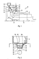
- FIG. 1 An apparatus for performing an ocular laser procedure is shown in Fig. 1 and is generally designated 10.
- the apparatus 10 includes a stationary surgical laser system 12 and a platform 14, which for the embodiment shown is a motorized chair.
- the platform 14 is configured to support a patient 16, and is moveable to align the eye 18 of the patient 16 with an eye stabilizing element 20 which is rigidly attached to the laser system 12.
- the laser system 12 can be moved relative to the platform 14 to accomplish this same purpose. Once aligned, the platform 14 can be moved to engage the eye 18 with the eye stabilizing element 20.
- the laser system 12 also includes a laser source 22 for generating a laser beam and directing the beam along beam path 24, as shown.
- Laser source 22 is activated and controlled by a system controller 26 via cable 28.
- the system controller 26 typically includes a software equipped computer processor. Also shown, the system controller 26 is connected to a graphical user interface 30 via cable 32 which is provided to receive instructions from, and present information to, a system operator (not shown).
- Fig. 1 further shows that an electrical cable 34 connects the system controller 26 to the platform 14.
- the platform 14 is configured for independent movement along each of three mutually orthogonal axes (e.g. x, y and z axes) in response to a control signal from a system controller 26. These axes are shown in Fig. 1 (axes y and z) and Fig. 3 (axes x and y).
- the platform 14 can be moved using three individually controllable stepper motors (not shown) that are selectively energized to move the platform 14 incrementally in response to the control signal.
- Fig. 2 shows the eye stabilizing element 20 in greater detail.
- the eye stabilizing element 20 is mounted on the laser system 12 and includes a hollow, base member 36 which is substantially shaped as a truncated cone and defines a longitudinal axis 38.
- the eye stabilizing element 20 also includes a curved lens 40 that is substantially centered on the axis 38 and is formed with a surface 42 for contacting the anterior surface 44 of the cornea 46 of the eye 18.
- the contact surface 42 of lens 40 will typically have a radius of curvature that is approximately 8.8mm and be made of a dear, transparent material such as Poly(methyl) methacrylate.
- the eye 18 will be illuminated through the curved contact glass of the lens 40.
- the optical detectors 58 and 60 can then be used to detect the structure of the contact glass of the lens 40, as well as anatomical structures of the patient's eye (e.g. pupil, iris or retina). Alternatively, reflections of the illumination from the contact glass of the lens 40, and the anterior surface 44 of the eye 18 can be used for detection purposes.
- the eye stabilizing element 20 includes a recessed vacuum channel 48 that is formed at the periphery of the lens 40. Additionally, a passageway 50 is formed in the base member 36 to establish fluid communication between the vacuum channel 48 and a vacuum pump 52.
- the eye stabilizing element 20 can be engaged with the eye 18. Specifically, as described further herein, the eye 18 is first aligned in the x-y plane (see Fig. 3 ) with the eye stabilizing element 20. Next, the eye 18 is moved toward the eye stabilizing element 20 until the anterior surface 44 of the cornea 46 contacts the surface 42 of the lens 40. At this point, the vacuum pump 52 is activated to establish a vacuum in the channel 48 to hold the eye 18 against the eye stabilizing element 20.
- the apparatus 10 To align the eye 18 with the eye stabilizing element 20, the apparatus 10 includes a ring shaped marker 54 that is mounted on the eye stabilizing element 20 as shown in Fig. 2 . As further shown, an illumination system 56 is positioned and configured to directly illuminate the eye 18. As shown in Fig. 1 , the apparatus 10 also includes a pair of optical detectors 58, 60 (e.g. cameras) that are connected to the system controller 26 via respective cables 62, 64.
- a dichroic (or partially silvered) mirror 68 e.g. cameras
- the dichroic (or partially silvered) mirror 68 allows a portion of the reflected light to be observed by the surgeon at a surgeon's microscope 72.
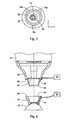
- Fig. 3 illustrates the relative position of the eye 18 and marker 54 as viewed by the detector 58.
- the system controller 26 can use an image processing algorithm to establish a measured alignment of the eye 18 relative to the eye stabilization element 20.
- the system controller 26 can determine the relative location of a specific anatomical feature of the eye 18, such as the iris 74, shown in Fig. 3 .
- the pupil, the iris, or some non-anatomical feature, such as a mark (not shown) made on the eye 18, can be used to determine the relative alignment between the eye 18 and the marker 54, or some component of the laser system 12.
- a measured alignment of the eye 18 relative to the eye stabilizing element 20 in an x-y plane is established by the system controller 26 using an image obtained by the detector 58. Then, the system controller 26 compares the measured alignment to the desired alignment to determine an alignment difference and generates an error signal that is indicative of the alignment difference.
- the error signal is then sent from the system controller 26 to the platform 14 where it is used to incrementally move the platform 14 in an appropriate direction. Typically, this involves the selective activation of a plurality of individually controllable stepper motors (not shown).
- a second image which includes the marker 54 and reflections from the eye 18 is obtained by the detector 58 and used by the system controller 26 to determine a second alignment difference.
- This second alignment difference is used by the system controller 26 to generate a second error signal and cause a second movement of platform 14.
- the process is then repeated, as many times as necessary, until the desired alignment in the x-y plane between the eye 18 and laser system 12 is achieved (i.e. the x-y alignment difference is zero).
- the apparatus 10 can be used to maintain an alignment between the eye 18 and laser system 12 in spite of movements (i.e. involuntary movements) of the eye 18.
- the platform 14 is then moved in the z direction until contact is established between the anterior surface 44 of the cornea 46 and the surface 42 of the lens 40 (see Fig. 2 ). During this z movement, alignment in the x-y plane can be maintained using the detector 58 as described above. In addition, movements of the platform 14 in the z direction can be monitored by the optical detector 60 shown in Fig. 1 .
- each sensor 76a-c is positioned to measure a contact pressure between the eye 18 and the laser eye stabilizing element 20.
- the pressure sensors 76a-c can be strain gauges or other sensors known in the pertinent art. Outputs from the pressure sensors 76a-c are provided to the system controller 26 via cables (not shown). As best seen in Fig. 3 , the three sensors 76a-c are uniformly distributed around the laser delivery beam path 66 and oriented to measure contact pressures that are directed parallel to the beam path 66.
- the sensors 76a-c can be used to ensure that dangerous pressure levels are not exerted on the eye 18.
- the sensors 76a-c can be used to detect misalignments and augment alignment using the detector 58. More specifically, a misalignment between the eye 18 and eye stabilizing element 20 will result in pressure differences between adjacent pressure sensors 76a-c. The platform 14 can then be moved to reduce these pressure gradients and ensure correct alignment.
- the sensors 76a-c can be used to mechanically deform portions of the eye 18 into a selected shape by allowing a predetermined pressure gradient to be established during contact and engagement of the eye 18 and laser system 12.
- the vacuum pump 52 is activated to establish a vacuum in the channel 48 to hold the eye 18 against the eye stabilizing element 20.
- continuous monitoring by the pressure sensors 76a-c can be performed to ensure that dangerous pressure levels are not exerted on the eye 18.
- Fig. 4 illustrates another embodiment in accordance with the present invention in which the eye stabilizing element 20' is first installed on the eye 18' and held there by the application of suction from vacuum pump 52'.
- an adapter 78' is mounted on the laser system 12' for engagement with the eye stabilizing element 20'.
- the eye stabilizing element 20' and adapter 78' are formed with engagement features that allow the eye stabilizing element 20' to be coupled to and engage with the adapter 78'.
- These engagement features include an inner conical surface 82' formed on the eye stabilizing element 20' which contacts an outer conical surface 84' formed on the adapter 78'.
- the eye stabilizing element 20' is advanced onto the adapter 78' until a rim 86' on the eye stabilizing element 20' contacts and abuts a shelf 88' that is formed on the adapter 78'.
- a suction can then be established in channel 90' by vacuum pump 92' to hold the eye stabilizing element 20' and adapter 78' together.
- a marker 54' is mounted on the eye stabilizing element 20' and a marker 94' is mounted on the adapter 78'.
- a detector such as the detector 58 shown in Fig. 1 , can be used to align the eye stabilizing element 20' with the adapter 78' as described above.
Landscapes
- Health & Medical Sciences (AREA)
- Ophthalmology & Optometry (AREA)
- Optics & Photonics (AREA)
- Physics & Mathematics (AREA)
- Heart & Thoracic Surgery (AREA)
- Surgery (AREA)
- Engineering & Computer Science (AREA)
- Biomedical Technology (AREA)
- Nuclear Medicine, Radiotherapy & Molecular Imaging (AREA)
- Vascular Medicine (AREA)
- Life Sciences & Earth Sciences (AREA)
- Animal Behavior & Ethology (AREA)
- General Health & Medical Sciences (AREA)
- Public Health (AREA)
- Veterinary Medicine (AREA)
- Laser Surgery Devices (AREA)
- Eye Examination Apparatus (AREA)
Abstract
Description
- The present invention pertains generally to devices and methods for performing ocular laser surgery. More particularly, the present invention pertains to devices for positioning the eye of a patient for laser surgery. The present invention is useful as a device for establishing a contact alignment between a patient's eye and a laser system to facilitate the engagement of the eye with the laser system prior to a refractive laser surgery procedure.
- Surgical lasers are now commonly used in a variety of ophthalmic applications, including the diagnosis and treatment of ocular diseases, as well as the diagnosis and correction of optical deficiencies. As an example, corneal reshaping procedures using lasers, such as the well known LASIK procedure, are now widely available. In all of these procedures, the surgical laser is chosen as the tool of choice because of the ability of the laser to be accurately focused on extremely small amounts of ocular tissue. In addition, the ability of the laser to be guided to prescribed locations within the eye with precision and reliability has enabled a whole new class of ophthalmic procedures that require nothing short of pinpoint accuracy. Unfortunately, movements of the eye relative to the laser source can undermine the accuracy of the laser and reduce the efficacy of the laser procedure.
- With the above in mind, movements of the eye can be classified broadly into two groups, namely, voluntary movements and involuntary movements. Voluntary movements can often be almost completely eliminated in most patients by instructing the patient to concentrate (i.e. fixate) on a target such as a small light source. On the other hand, involuntary eye movements cannot be remedied by instruction, and as a consequence, they must be somehow controlled. Included in the involuntary eye movements are movements due to the patient's pulse, movements due to the patient breathing, and psychotic eye movements which can occur, for example, when a patient is startled.
- It can be easily appreciated that these involuntary movements can have an adverse effect on a laser operation unless the movements are either compensated for, or effectively eliminated. With regard to the former, eye tracking systems have been proposed to compensate for eye movement during a procedure. In simple terms, these tracking systems measure movements of the eye during a procedure and provide a real time signal indicating eye position to the laser system. In response to the signal, the laser system moves, and in some cases reshapes, the laser beam to follow the movements of the eye. Unfortunately, these eye tracking systems tend to be overly complicated, and, as a practical matter, do not always provide the reliability that is required for certain types of procedures. For example, for procedures wherein the laser is configured to ablate and destroy selected tissue, an error or malfunction of the tracking system can result in the immediate destruction of non-target tissue.
- Unlike eye tracking systems which attempt to compensate for eye movements, eye stabilization systems can be used to effectively eliminate eye movements, and are generally more reliable and less complicated than eye tracking systems. In addition to eliminating eye movement, some eye stabilization systems can be used to establish a desirable alignment between the eye and the laser source. Moreover, the eye stabilization element can be attached to the laser system to establish and maintain an optimal (and known) optical path length between the eye and laser system.
- One factor that is worthy of consideration when contemplating the use of an eye stabilization and alignment device is the comfort and safety of the patient. In this regard, eye stabilization devices typically apply a mechanical pressure to the eye for the purpose of restraining the eye. Generally, this pressure is applied to the surface of the eye (i.e. the sclera, limbus or cornea). For obvious reasons, large pressures applied to the eye are often uncomfortable to the patient and can result in post-operative pain and scarring. Moreover, the pressure can cause damage to the eye by increasing the intra-ocular pressure of the eye to dangerous levels.
- For some eye stabilizing devices, a stabilizing element is first attached to the eye and thereafter the stabilizing element is aligned with and attached to a coupler or adapter on the laser source. For these types of devices, the pressures exerted on the eye during both stabilization and coupling to the laser source must be considered. In addition to the constraints described above, an eye stabilizing and alignment device must also be positioned such that it does not interfere with the laser procedure. Specifically, this implies that opaque portions of the device do not lie along the laser delivery beam path.
- With regard to the process of aligning and attaching an eye to a laser system, as indicated above, this procedure must be carried out carefully to avoid the exertion of dangerous pressure levels on the eye. Heretofore, these alignment and "docking" procedures have generally been done manually. Specifically, this means that the movement of the eye relative to the laser system has needed to be observed visually by the surgeon and controlled by the hand of the surgeon. In these procedures, movements of the eye must be accommodated and corrected for and this often results in a relatively slow, labor intensive procedure, the satisfactory performance of which is highly dependent on the skill and patience of the surgeon. Document
US-A-2004/0044333 relates to a corneal surgery apparatus capable of obtaining positional information on an eye during laser irradiation and controlling the alignment and the torsion of the patient's head. - In light of the above, it is an objective of the present invention to provide a device and method for aligning a patient's eye relative to a laser system to facilitate an engagement between the eye and laser system. Another object of the present invention is to provide an automated device for aligning a patient's eye relative to a laser system which does not rely exclusively on human eye hand coordination. Yet another object of the present invention is to provide a device and method for aligning and engaging a patient's eye with a laser system without damaging the eye. Still another object of the present invention is to provide a device and method for aligning a patient's eye relative to a laser system that is easy to use, relatively simple to manufacture, and comparatively cost effective.
- The present invention is directed to a device for establishing a desired contact alignment between a patient's eye and a laser system. Once properly aligned, the eye can be safely engaged with the laser system to hold the eye stationary relative to the laser system. This fixed arrangement then allows a surgical beam to be accurately delivered from a source and focused to a selected ocular location.
- As intended for the device of the present invention, a platform is provided for supporting the patient during a surgical procedure. Further, the platform is moveable relative to a laser system. Typically, the platform is configured for independent movement along each of three mutually orthogonal axes (e.g. x, y and z axes), and is moveable in response to a control signal from a system controller. In an alternate arrangement for the device of the present invention, the laser system can be mounted on the moveable platform, and the combination of platform and laser system can be reconfigured to control movement of the laser system relative to the patient's eye.
- To determine a relative alignment between the eye and the laser system, the device includes a detector and, preferably, an illumination system also. In one embodiment, the illumination system is positioned and configured to directly illuminate the eye. Reflections from an anatomical feature of the eye are then imaged using a detector and this image, which is indicative of the spatial position of the eye, is transmitted to the system controller. Also for this embodiment, a marker can be mounted on the laser system to provide an indication of the laser system's position. Alternatively, a component of the laser system can be used for this purpose. In either case, the marker (or component) is then imaged using the detector. Then, along with the reflections from the eye, the marker (component) image is transmitted to the system controller. There, at the system controller, images of the respective spatial positions of the eye and the laser system are processed to determine a measured alignment of the eye relative to the laser system. This measured alignment is then compared to the desired alignment to determine an alignment difference. An error signal is then generated that is indicative of the alignment difference.
- For the alignment device, the error signal from the system controller is used to incrementally move the platform in an appropriate direction. For example, the platform can be a motorized chair having a plurality of individually controllable stepper motors that are selectively energized in response to the error signal. After the first chair movement described above has been accomplished, a second image can be evaluated. This second image, which includes the marker and reflections from the eye, is detected and used to determine a more refined second alignment difference. This second alignment difference, in turn, is used by the system controller to generate a second error signal and cause a second chair movement. The process is then repeated, as many times as necessary, until the desired alignment between the eye and laser system is achieved (i.e. the alignment difference is zero).
- In a particular embodiment of the present invention, the alignment device is used to align an eye stabilizing element (e.g. contact lens, suction ring, etc.) with the eye to facilitate an engagement between the eye and the eye stabilizing element. For this embodiment, the eye stabilizing element is first fixedly attached to the laser system. Once the eye stabilizing element is aligned with the eye as described above, the eye stabilizing element is advanced toward the eye to contact and engage an anterior surface of the eye. For example, the eye stabilizing element can contact and engage the cornea, limbus, sclera and combinations thereof.
- In another embodiment, the eye stabilizing element is first installed on the eye for movement therewith. For example, a contact lens with an integral suction ring, or a suction ring alone, can be positioned on the eye and affixed thereto by the application of a suitable suction ring vacuum. For this embodiment, an adapter is mounted on the laser source for interaction with the eye stabilizing element. Specifically, the eye stabilizing element is formed with an engagement feature that can be coupled to a mating feature that is formed on the adapter.
- It is to be appreciated that within the context of the present disclosure, several detector arrangements can be employed to create the image(s) necessary to align the eye with the laser system as described above. With the above caveat in mind, however, one arrangement of particular interest includes two detectors. For this arrangement, a first detector is positioned to create an image that indicates misalignments between the eye and laser system in a plane normal to a laser delivery beam path (i.e. misalignments in an x-y plane). On the other hand, the second detector is positioned to give positional information about the eye and laser system along the laser delivery beam path (i.e. in a z-direction). With this cooperation of structure, the alignment device can be used to initially align the eye and laser system (or, if applicable, the eye stabilizing element and adapter) in the x-y plane. Once aligned in the x-y plane, the eye can be moved in the z-direction toward the laser system. During this z-movement, the alignment device measures and maintains alignment in the x-y plane. Z-axis movement is then continued until the eye is engaged with the laser system (or, if applicable, the eye stabilizing element is engaged with the adapter).
- In another aspect of the present invention, an embodiment of the alignment device can include a plurality of pressure sensors that are mounted on the laser system. More specifically, each sensor is positioned to measure a contact pressure between the eye and the laser system (or, if applicable, between the eye stabilizing element and the adapter). In one arrangement, three sensors are uniformly distributed around the laser delivery beam path and oriented to measure contact pressures that are directed parallel to the beam path. With this interactive cooperation of structure, the sensors can be used to perform one or more of the following functionalities: 1) to detect misalignments and augment the optical alignment device that is described above, 2) to ensure that dangerous pressure levels are not exerted on the patient's eye, and 3) to mechanically deform portions of the eye into a selected shape by placing a predetermined pressure gradient on the eye during engagement of the eye and laser system.
- The novel features of this invention, as well as the invention itself, both as to its structure and its operation, will be best understood from the accompanying drawings, taken in conjunction with the accompanying description, in which similar reference characters refer to similar parts, and in which:
-
Fig. 1 is a front plan view of an apparatus for performing an ocular laser procedure on a patient having a device for aligning and engaging the patient's eye with a laser system, shown with portions broken away for clarity; -
Fig. 2 is a cross sectional view of a portion of the apparatus ofFig. 1 , as seen along the line 2-2 inFig. 1 ; -
Fig. 3 is a view as seen along the line 2-2 inFig. 1 showing a plurality of pressure sensors for measuring contact pressures during alignment and engagement of the eye with an eye stabilizing element; and -
Fig. 4 is an exploded cross-sectional view of an eye stabilizing device in accordance with the present invention. - An apparatus for performing an ocular laser procedure is shown in
Fig. 1 and is generally designated 10. As shown, the apparatus 10 includes a stationarysurgical laser system 12 and aplatform 14, which for the embodiment shown is a motorized chair. For the apparatus 10, theplatform 14 is configured to support apatient 16, and is moveable to align theeye 18 of the patient 16 with aneye stabilizing element 20 which is rigidly attached to thelaser system 12. On the other hand, thelaser system 12 can be moved relative to theplatform 14 to accomplish this same purpose. Once aligned, theplatform 14 can be moved to engage theeye 18 with theeye stabilizing element 20. - For the apparatus 10, the
laser system 12 also includes alaser source 22 for generating a laser beam and directing the beam alongbeam path 24, as shown.Laser source 22 is activated and controlled by asystem controller 26 viacable 28. For the apparatus 10, thesystem controller 26 typically includes a software equipped computer processor. Also shown, thesystem controller 26 is connected to agraphical user interface 30 viacable 32 which is provided to receive instructions from, and present information to, a system operator (not shown). -
Fig. 1 further shows that anelectrical cable 34 connects thesystem controller 26 to theplatform 14. Typically, theplatform 14 is configured for independent movement along each of three mutually orthogonal axes (e.g. x, y and z axes) in response to a control signal from asystem controller 26. These axes are shown inFig. 1 (axes y and z) andFig. 3 (axes x and y). For example, theplatform 14 can be moved using three individually controllable stepper motors (not shown) that are selectively energized to move theplatform 14 incrementally in response to the control signal. -
Fig. 2 shows theeye stabilizing element 20 in greater detail. As shown there, theeye stabilizing element 20 is mounted on thelaser system 12 and includes a hollow,base member 36 which is substantially shaped as a truncated cone and defines alongitudinal axis 38. Theeye stabilizing element 20 also includes acurved lens 40 that is substantially centered on theaxis 38 and is formed with asurface 42 for contacting theanterior surface 44 of thecornea 46 of theeye 18. For this purpose, thecontact surface 42 oflens 40 will typically have a radius of curvature that is approximately 8.8mm and be made of a dear, transparent material such as Poly(methyl) methacrylate. When alens 40 is used, theeye 18 will be illuminated through the curved contact glass of thelens 40. Theoptical detectors lens 40, as well as anatomical structures of the patient's eye (e.g. pupil, iris or retina). Alternatively, reflections of the illumination from the contact glass of thelens 40, and theanterior surface 44 of theeye 18 can be used for detection purposes. - As further shown in
Fig. 2 , theeye stabilizing element 20 includes a recessedvacuum channel 48 that is formed at the periphery of thelens 40. Additionally, apassageway 50 is formed in thebase member 36 to establish fluid communication between thevacuum channel 48 and avacuum pump 52. With this cooperation of structure, theeye stabilizing element 20 can be engaged with theeye 18. Specifically, as described further herein, theeye 18 is first aligned in the x-y plane (seeFig. 3 ) with theeye stabilizing element 20. Next, theeye 18 is moved toward theeye stabilizing element 20 until theanterior surface 44 of thecornea 46 contacts thesurface 42 of thelens 40. At this point, thevacuum pump 52 is activated to establish a vacuum in thechannel 48 to hold theeye 18 against theeye stabilizing element 20. - To align the
eye 18 with theeye stabilizing element 20, the apparatus 10 includes a ring shapedmarker 54 that is mounted on theeye stabilizing element 20 as shown inFig. 2 . As further shown, anillumination system 56 is positioned and configured to directly illuminate theeye 18. As shown inFig. 1 , the apparatus 10 also includes a pair ofoptical detectors 58, 60 (e.g. cameras) that are connected to thesystem controller 26 viarespective cables illumination system 56 activated, reflections from theeye 18 andmarker 54 traveling alongbeam path 66 are reflected by a dichroic (or partially silvered)mirror 68 and passed alongbeam path 70 to thedetector 58. In addition, the dichroic (or partially silvered)mirror 68 allows a portion of the reflected light to be observed by the surgeon at a surgeon'smicroscope 72. -
Fig. 3 illustrates the relative position of theeye 18 andmarker 54 as viewed by thedetector 58. With this image, thesystem controller 26 can use an image processing algorithm to establish a measured alignment of theeye 18 relative to theeye stabilization element 20. For this purpose, thesystem controller 26 can determine the relative location of a specific anatomical feature of theeye 18, such as theiris 74, shown inFig. 3 . Alternatively, the pupil, the iris, or some non-anatomical feature, such as a mark (not shown) made on theeye 18, can be used to determine the relative alignment between theeye 18 and themarker 54, or some component of thelaser system 12. - With cross reference to
Figs. 1 and3 , it is to be appreciated that a measured alignment of theeye 18 relative to theeye stabilizing element 20 in an x-y plane is established by thesystem controller 26 using an image obtained by thedetector 58. Then, thesystem controller 26 compares the measured alignment to the desired alignment to determine an alignment difference and generates an error signal that is indicative of the alignment difference. - The error signal is then sent from the
system controller 26 to theplatform 14 where it is used to incrementally move theplatform 14 in an appropriate direction. Typically, this involves the selective activation of a plurality of individually controllable stepper motors (not shown). After thefirst platform 14 movement described above, a second image which includes themarker 54 and reflections from theeye 18 is obtained by thedetector 58 and used by thesystem controller 26 to determine a second alignment difference. This second alignment difference, in turn, is used by thesystem controller 26 to generate a second error signal and cause a second movement ofplatform 14. The process is then repeated, as many times as necessary, until the desired alignment in the x-y plane between theeye 18 andlaser system 12 is achieved (i.e. the x-y alignment difference is zero). Moreover, the apparatus 10 can be used to maintain an alignment between theeye 18 andlaser system 12 in spite of movements (i.e. involuntary movements) of theeye 18. - Once the
eye 18 andeye stabilizing element 20 are aligned in the x-y plane as described above, theplatform 14 is then moved in the z direction until contact is established between theanterior surface 44 of thecornea 46 and thesurface 42 of the lens 40 (seeFig. 2 ). During this z movement, alignment in the x-y plane can be maintained using thedetector 58 as described above. In addition, movements of theplatform 14 in the z direction can be monitored by theoptical detector 60 shown inFig. 1 . - Cross referencing
Figs. 2 and3 , it can be seen that threepressure sensors 76a-c are interposed between theeye stabilizing element 20 and thelaser system 12. With this arrangement, eachsensor 76a-c is positioned to measure a contact pressure between theeye 18 and the lasereye stabilizing element 20. For the apparatus 10, thepressure sensors 76a-c can be strain gauges or other sensors known in the pertinent art. Outputs from thepressure sensors 76a-c are provided to thesystem controller 26 via cables (not shown). As best seen inFig. 3 , the threesensors 76a-c are uniformly distributed around the laserdelivery beam path 66 and oriented to measure contact pressures that are directed parallel to thebeam path 66. With this structure, thesensors 76a-c can be used to ensure that dangerous pressure levels are not exerted on theeye 18. In addition, thesensors 76a-c can be used to detect misalignments and augment alignment using thedetector 58. More specifically, a misalignment between theeye 18 andeye stabilizing element 20 will result in pressure differences betweenadjacent pressure sensors 76a-c. Theplatform 14 can then be moved to reduce these pressure gradients and ensure correct alignment. In yet another implementation, thesensors 76a-c can be used to mechanically deform portions of theeye 18 into a selected shape by allowing a predetermined pressure gradient to be established during contact and engagement of theeye 18 andlaser system 12. - Once proper contact has been established between the
eye 18 and theeye stabilizing element 20, thevacuum pump 52 is activated to establish a vacuum in thechannel 48 to hold theeye 18 against theeye stabilizing element 20. During activation of thevacuum pump 52, continuous monitoring by thepressure sensors 76a-c can be performed to ensure that dangerous pressure levels are not exerted on theeye 18. -
Fig. 4 illustrates another embodiment in accordance with the present invention in which the eye stabilizing element 20' is first installed on theeye 18' and held there by the application of suction from vacuum pump 52'. For this embodiment, anadapter 78' is mounted on the laser system 12' for engagement with the eye stabilizing element 20'. Specifically, as shown, the eye stabilizing element 20' andadapter 78' are formed with engagement features that allow the eye stabilizing element 20' to be coupled to and engage with theadapter 78'. These engagement features include an inner conical surface 82' formed on the eye stabilizing element 20' which contacts an outer conical surface 84' formed on theadapter 78'. During engagement, the eye stabilizing element 20' is advanced onto theadapter 78' until a rim 86' on the eye stabilizing element 20' contacts and abuts a shelf 88' that is formed on theadapter 78'. A suction can then be established in channel 90' by vacuum pump 92' to hold the eye stabilizing element 20' andadapter 78' together. A more detailed description of a suitable eye stabilizing element 20' andadapter 78' are provided in co-owned, co-pendingU.S. Patent Application No. 10/790,625 filed March 1, 2004 - As further shown in
Fig. 4 , a marker 54' is mounted on the eye stabilizing element 20' and a marker 94' is mounted on theadapter 78'. With the structure, a detector, such as thedetector 58 shown inFig. 1 , can be used to align the eye stabilizing element 20' with theadapter 78' as described above. - While the particular Device and Method for Aligning an Eye with a Surgical Laser and corresponding methods of use as herein shown and disclosed in detail are fully capable of obtaining the objects and providing the advantages herein before stated, it is to be understood that they are merely illustrative of the presently preferred embodiments of the invention and that no limitations are intended to the details of construction or design herein shown other than as described in the appended claims.
Claims (14)
- A device for establishing a predetermined contact alignment between an eye (18) of a patient (16) and a laser system (12) during ocular surgery which comprises:at least one detector (58, 60) for detecting a spatial position of the eye (18) and a spatial position of the laser system (12);a controller means (26) for determining an alignment difference between the spatial position of the eye (18) and the spatial position of the laser system (12);a means for altering the alignment difference between the eye (18) and the laser system (12) to establish the predetermined contact alignment; characterized in thatat least one pressure sensor (76 a-c) is mounted on the laser system (12) for measuring a contact pressure on the eye (18) during contact between the eye (18) and the laser system (12).
- A device as recited in claim 1 further comprising
a switch interconnecting the pressure sensor (76 a-c) with the altering means for stopping the altering means whenever the pressure exceeds a predetermined level. - A device as recited in claim 1 further comprising:at least three pressure sensors (76 a-c) mounted on the laser system (12) for measuring a respective contact pressure on the eye (18) during contact between the eye (18) and the laser system (12); anda computer means for calculating a pressure differential between each sensor (76 a-c) and each other sensor (76 a-c), wherein the altering means is activated by the computer means to substantially nullify all pressure differentials.
- A device as recited in claim 1 wherein the altering means moves the patient (16) or
wherein the altering means moves the laser system (12) or
wherein the detector (58, 60) includes a camera. - A device as recited in claim 1 further comprising:a contact lens (40) mounted on the laser system (12) for engagement with the eye (18) during the refractive surgery; anda marker (54) positioned on the laser system (12), wherein the marker (54) is indicative of the spatial position of the laser system (12).
- A device as recited in claim 1 wherein the spatial position of the eye (18) is determined by detecting an anatomical structure of the eye (18).
- A device as recited in one of claims 1 to 4 or 6,
wherein the controller is configured to generate a control signal indicative of an alignment difference between a spatial position of the eye (18) and a spatial position of the laser system (12); and
wherein the means for altering the alignment difference between the eye and the laser system includes a motorized platform (14) for supporting the eye (18) and the laser system (12), the platform (14) being reconfigurable in response to the control signal to effect a relative movement between the eye (18) and the laser system (12) to engage the eye (18) of the patient (16) with the laser system (12). - A device as recited in claim 7 wherein the detector (58, 60) comprises:a marker (54) positioned on the laser system (12);an illumination system (56) for creating a light pattern from the eye (18); andat least one camera for simultaneously imaging the marker (54) and the light pattern for use in generating the control signal.
- A device as recited in claim 8 further comprising a contact lens (40) mounted on the laser system (12) for engagement with the eye (18) and wherein the marker (54) is affixed to the contact lens (40) or
wherein the light pattern is created by reflections from an anatomical structure of the eye (18) or
wherein the light pattern is created by reflections from an exposed anterior surface (44) of the eye (18). - A device as recited in claim 7 wherein the eye (18') is attached to an eye stabilizing device (20') and an adapter (78') is mounted on the laser source and wherein the device is configured to receive light reflected
from the eye stabilizing element (20') to generate the control signal. - A device as recited in claim 7 wherein the platform (14) supports and moves the patient (16) or
wherein the detector (58, 60) comprises a camera for simultaneously detecting the spatial position of the eye (18) and the spatial position of the laser system (12). - A method for aligning an eye (18) of a patient (16) with a surgical laser system to facilitate an engagement therebetween, the method comprising the steps of:configuring an optical detection system to generate a control signal indicative of an alignment difference between a spatial position of the eye (18) and a spatial position of the laser system (12);providing a motorized platform (14) for supporting the eye (18) and the laser system (12);reconfiguring the motorized platform (14) in response to the control signal to effect a relative movement between the eye (18) and the laser system (12) to engage the eye (18) of the patient (16) with the laser system (12); andmeasuring a contact pressure on the eye (18) during contact between the eye (18) and the laser system (12).
- A method as recited in claim 12, wherein the optical detection system comprises:a marker (54) positioned on the laser system (12);an illumination system for creating a pattern from the eye (18); andat least one camera for simultaneously imaging the marker (54) and the light pattern for use in generating the control signal.
- A method as recited in claim 12 or 13, further comprising the steps of:stopping the reconfiguration of the motorized platform (14) whenever the pressure exceeds a predetermined level.
Applications Claiming Priority (2)
| Application Number | Priority Date | Filing Date | Title |
|---|---|---|---|
| US11/066,726 US7390089B2 (en) | 2005-02-25 | 2005-02-25 | Device and method for aligning an eye with a surgical laser |
| PCT/IB2006/000002 WO2006090217A1 (en) | 2005-02-25 | 2006-01-04 | Device and mehtod for aligning an eye with a surgical laser |
Publications (2)
| Publication Number | Publication Date |
|---|---|
| EP1858460A1 EP1858460A1 (en) | 2007-11-28 |
| EP1858460B1 true EP1858460B1 (en) | 2011-09-21 |
Family
ID=36424635
Family Applications (1)
| Application Number | Title | Priority Date | Filing Date |
|---|---|---|---|
| EP06710216A Expired - Lifetime EP1858460B1 (en) | 2005-02-25 | 2006-01-04 | Device and method for aligning an eye with a surgical laser |
Country Status (6)
| Country | Link |
|---|---|
| US (1) | US7390089B2 (en) |
| EP (1) | EP1858460B1 (en) |
| JP (1) | JP4950077B2 (en) |
| AT (1) | ATE525048T1 (en) |
| ES (1) | ES2368939T3 (en) |
| WO (1) | WO2006090217A1 (en) |
Families Citing this family (120)
| Publication number | Priority date | Publication date | Assignee | Title |
|---|---|---|---|---|
| US6104959A (en) | 1997-07-31 | 2000-08-15 | Microwave Medical Corp. | Method and apparatus for treating subcutaneous histological features |
| US20120016349A1 (en) | 2001-01-29 | 2012-01-19 | Amo Development, Llc. | Hybrid ophthalmic interface apparatus and method of interfacing a surgical laser with an eye |
| US20080071254A1 (en) * | 2001-01-29 | 2008-03-20 | Advanced Medical Optics, Inc. | Ophthalmic interface apparatus and system and method of interfacing a surgical laser with an eye |
| US7402159B2 (en) * | 2004-03-01 | 2008-07-22 | 20/10 Perfect Vision Optische Geraete Gmbh | System and method for positioning a patient for laser surgery |
| DE102004030904A1 (en) * | 2004-06-25 | 2006-01-19 | Neuhann, Thomas, Prof.Dr.med. | Device for detecting the spatial position of the optical axis of an eye and for centering a reference system relative to the optical axis |
| DE102005046130A1 (en) * | 2005-09-27 | 2007-03-29 | Bausch & Lomb Inc. | Excimer laser-eye surgical system, has eye tracing device sending instruction signal to laser device via bidirectional bus to fire shot, when preset position data is same as initial position data of scanning device for shot |
| US9545338B2 (en) | 2006-01-20 | 2017-01-17 | Lensar, Llc. | System and method for improving the accommodative amplitude and increasing the refractive power of the human lens with a laser |
| US9889043B2 (en) | 2006-01-20 | 2018-02-13 | Lensar, Inc. | System and apparatus for delivering a laser beam to the lens of an eye |
| US8262646B2 (en) * | 2006-01-20 | 2012-09-11 | Lensar, Inc. | System and method for providing the shaped structural weakening of the human lens with a laser |
| US10842675B2 (en) | 2006-01-20 | 2020-11-24 | Lensar, Inc. | System and method for treating the structure of the human lens with a laser |
| US20070173796A1 (en) * | 2006-01-25 | 2007-07-26 | Ralf Kessler | Device and method for calibrating a laser system |
| US7620147B2 (en) | 2006-12-13 | 2009-11-17 | Oraya Therapeutics, Inc. | Orthovoltage radiotherapy |
| US7535991B2 (en) | 2006-10-16 | 2009-05-19 | Oraya Therapeutics, Inc. | Portable orthovoltage radiotherapy |
| DE102006053098A1 (en) * | 2006-11-10 | 2008-05-15 | Carl Zeiss Meditec Ag | Ophthalmological device for contacting therapy process i.e. femto-second Laser treatment, has detection device holding eye of patient on suspension device and determining indication about relative shift of suspension device |
| US20080218692A1 (en) * | 2007-03-06 | 2008-09-11 | Hopler Mark D | Reflectometry/Interferometry System and Method for Corneal Plane Positioning |
| DE502007002400D1 (en) | 2007-03-14 | 2010-02-04 | Wavelight Ag | Apparatus for coupling an element to the eye |
| EP2142125B1 (en) | 2007-04-19 | 2014-03-05 | Miramar Labs, Inc. | Devices, and systems for non-invasive delivery of microwave therapy |
| EP2532320A3 (en) | 2007-04-19 | 2013-04-03 | Miramar Labs, Inc. | Apparatus for reducing sweat production |
| WO2008131306A1 (en) | 2007-04-19 | 2008-10-30 | The Foundry, Inc. | Systems and methods for creating an effect using microwave energy to specified tissue |
| US9427285B2 (en) | 2007-04-19 | 2016-08-30 | Miramar Labs, Inc. | Systems and methods for creating an effect using microwave energy to specified tissue |
| US8688228B2 (en) | 2007-04-19 | 2014-04-01 | Miramar Labs, Inc. | Systems, apparatus, methods and procedures for the noninvasive treatment of tissue using microwave energy |
| US8512236B2 (en) * | 2008-01-11 | 2013-08-20 | Oraya Therapeutics, Inc. | System and method for positioning and stabilizing an eye |
| WO2008150330A1 (en) * | 2007-06-04 | 2008-12-11 | Oraya Therapeutics, Inc. | Device and assembly for positioning, stabilizing and treating an eye |
| ES2600146T3 (en) * | 2007-06-04 | 2017-02-07 | Oraya Therapeutics, Inc. | Set to position, stabilize and treat an eye |
| US8363783B2 (en) | 2007-06-04 | 2013-01-29 | Oraya Therapeutics, Inc. | Method and device for ocular alignment and coupling of ocular structures |
| JP5623907B2 (en) * | 2007-09-05 | 2014-11-12 | アルコン レンゼックス, インコーポレーテッド | Laser-induced protective shield in laser surgery |
| US9456925B2 (en) * | 2007-09-06 | 2016-10-04 | Alcon Lensx, Inc. | Photodisruptive laser treatment of the crystalline lens |
| WO2009033107A2 (en) * | 2007-09-06 | 2009-03-12 | Lensx Lasers, Inc. | Photodisruptive treatment of crystalline lens |
| WO2009033111A2 (en) | 2007-09-06 | 2009-03-12 | Lensx Lasers, Inc. | Precise targeting of surgical photodisruption |
| WO2009036098A2 (en) * | 2007-09-10 | 2009-03-19 | Lensx Lasers, Inc. | Apparatus, systems and techniques for interfacing with an eye in laser surgery |
| EP2197382A4 (en) * | 2007-09-10 | 2013-01-23 | Alcon Lensx Inc | Effective laser photodisruptive surgery in a gravity field |
| DE112008002511T5 (en) * | 2007-09-18 | 2010-07-15 | LenSx Lasers, Inc., Aliso Viejo | Methods and devices for integrated cataract surgery |
| US20090137991A1 (en) * | 2007-09-18 | 2009-05-28 | Kurtz Ronald M | Methods and Apparatus for Laser Treatment of the Crystalline Lens |
| WO2009059251A2 (en) * | 2007-11-02 | 2009-05-07 | Lensx Lasers, Inc. | Methods and apparatus for improved post-operative ocular optical peformance |
| US8632526B2 (en) * | 2007-11-07 | 2014-01-21 | Amo Development, Llc | System and method of interfacing a surgical laser with an eye |
| KR102052152B1 (en) * | 2007-12-12 | 2020-01-08 | 미라마 랩스 인코포레이티드 | A disposable medical apparatus for use with an applicator which radiates microwave energy |
| EP3272395B1 (en) | 2007-12-23 | 2019-07-17 | Carl Zeiss Meditec, Inc. | Devices for detecting, controlling, and predicting radiation delivery |
| US7801271B2 (en) | 2007-12-23 | 2010-09-21 | Oraya Therapeutics, Inc. | Methods and devices for orthovoltage ocular radiotherapy and treatment planning |
| ES2690975T3 (en) * | 2008-01-09 | 2018-11-23 | Alcon Lensx, Inc. | Fragmentation of tissue by photodisruptive laser |
| EP2271276A4 (en) | 2008-04-17 | 2013-01-23 | Miramar Labs Inc | Systems, apparatus, methods and procedures for the noninvasive treatment of tissue using microwave energy |
| US8246609B2 (en) * | 2008-06-27 | 2012-08-21 | Amo Development, Llc. | Intracorneal inlay, system, and method |
| MX2011000095A (en) | 2008-06-30 | 2011-05-30 | Wavelight Gmbh | Device for ophthalmologic, particularly refractive, laser surgery. |
| RU2474405C2 (en) * | 2008-06-30 | 2013-02-10 | Уэйвлайт Гмбх | Apparatus for ophthalmological, particularly, refraction laser surgical operation |
| US8500723B2 (en) | 2008-07-25 | 2013-08-06 | Lensar, Inc. | Liquid filled index matching device for ophthalmic laser procedures |
| US8480659B2 (en) | 2008-07-25 | 2013-07-09 | Lensar, Inc. | Method and system for removal and replacement of lens material from the lens of an eye |
| RU2485923C2 (en) * | 2008-08-25 | 2013-06-27 | Уэйвлайт Гмбх | Method of ensuring contact of eye with laser device |
| WO2011003431A1 (en) * | 2009-07-10 | 2011-01-13 | Wavelight Gmbh | Device for cutting a tissue part of an eye by means of laser radiation |
| US10624787B2 (en) | 2009-07-10 | 2020-04-21 | Alcon Inc. | Apparatus for cutting a tissue section of an eye by laser radiation |
| AU2010276360A1 (en) * | 2009-07-24 | 2012-02-16 | Lensar, Inc. | Liquid holding interface device for ophthalmic laser procedures |
| US8758332B2 (en) | 2009-07-24 | 2014-06-24 | Lensar, Inc. | Laser system and method for performing and sealing corneal incisions in the eye |
| CA2769097A1 (en) | 2009-07-24 | 2011-01-27 | Lensar, Inc. | System and method for performing ladar assisted procedures on the lens of an eye |
| JP2013500078A (en) | 2009-07-24 | 2013-01-07 | レンサー, インク. | System and method for irradiating a lens of an eye with a laser irradiation pattern |
| US8617146B2 (en) | 2009-07-24 | 2013-12-31 | Lensar, Inc. | Laser system and method for correction of induced astigmatism |
| US8382745B2 (en) | 2009-07-24 | 2013-02-26 | Lensar, Inc. | Laser system and method for astigmatic corrections in association with cataract treatment |
| US8267925B2 (en) * | 2009-07-29 | 2012-09-18 | Alcon Lensx, Inc. | Optical system for ophthalmic surgical laser |
| US9504608B2 (en) | 2009-07-29 | 2016-11-29 | Alcon Lensx, Inc. | Optical system with movable lens for ophthalmic surgical laser |
| US8262647B2 (en) * | 2009-07-29 | 2012-09-11 | Alcon Lensx, Inc. | Optical system for ophthalmic surgical laser |
| US8419721B2 (en) * | 2009-07-29 | 2013-04-16 | Alcon Lensx, Inc. | Optical system for ophthalmic surgical laser |
| US8506559B2 (en) * | 2009-11-16 | 2013-08-13 | Alcon Lensx, Inc. | Variable stage optical system for ophthalmic surgical laser |
| US9492322B2 (en) | 2009-11-16 | 2016-11-15 | Alcon Lensx, Inc. | Imaging surgical target tissue by nonlinear scanning |
| CN102843955A (en) * | 2010-02-01 | 2012-12-26 | 雷萨公司 | Purkinjie image-based alignment of suction ring in ophthalmic applications |
| US8265364B2 (en) * | 2010-02-05 | 2012-09-11 | Alcon Lensx, Inc. | Gradient search integrated with local imaging in laser surgical systems |
| US8414564B2 (en) * | 2010-02-18 | 2013-04-09 | Alcon Lensx, Inc. | Optical coherence tomographic system for ophthalmic surgery |
| US8823488B2 (en) * | 2010-02-19 | 2014-09-02 | Wavelight Ag | Medical treatment system and method for operation thereof |
| US8398236B2 (en) | 2010-06-14 | 2013-03-19 | Alcon Lensx, Inc. | Image-guided docking for ophthalmic surgical systems |
| US8845624B2 (en) * | 2010-06-25 | 2014-09-30 | Alcon LexSx, Inc. | Adaptive patient interface |
| CN103228239B (en) | 2010-09-02 | 2015-04-01 | 眼科医疗公司 | Patient Interfaces for Ophthalmic Diagnostics and Interventional Procedures |
| US9532708B2 (en) | 2010-09-17 | 2017-01-03 | Alcon Lensx, Inc. | Electronically controlled fixation light for ophthalmic imaging systems |
| USD695408S1 (en) | 2010-10-15 | 2013-12-10 | Lensar, Inc. | Laser system for treatment of the eye |
| USD694890S1 (en) | 2010-10-15 | 2013-12-03 | Lensar, Inc. | Laser system for treatment of the eye |
| WO2012051490A1 (en) | 2010-10-15 | 2012-04-19 | Lensar, Inc. | System and method of scan controlled illumination of structures within an eye |
| US20120240939A1 (en) * | 2011-03-24 | 2012-09-27 | Jochen Kandulla | Apparatus and Method for Control of Refractive Index Changes in a Material |
| US10463541B2 (en) | 2011-03-25 | 2019-11-05 | Lensar, Inc. | System and method for correcting astigmatism using multiple paired arcuate laser generated corneal incisions |
| US8459794B2 (en) | 2011-05-02 | 2013-06-11 | Alcon Lensx, Inc. | Image-processor-controlled misalignment-reduction for ophthalmic systems |
| US9089401B2 (en) | 2011-05-06 | 2015-07-28 | Alcon Lensx, Inc. | Adjusting ophthalmic docking system |
| US9622913B2 (en) | 2011-05-18 | 2017-04-18 | Alcon Lensx, Inc. | Imaging-controlled laser surgical system |
| US9314301B2 (en) | 2011-08-01 | 2016-04-19 | Miramar Labs, Inc. | Applicator and tissue interface module for dermatological device |
| US8939967B2 (en) | 2011-08-03 | 2015-01-27 | Alcon Lensx, Inc. | Patient interface defogger |
| US8398238B1 (en) | 2011-08-26 | 2013-03-19 | Alcon Lensx, Inc. | Imaging-based guidance system for ophthalmic docking using a location-orientation analysis |
| US9237967B2 (en) | 2011-10-21 | 2016-01-19 | Optimedica Corporation | Patient interface for ophthalmologic diagnostic and interventional procedures |
| US8863749B2 (en) | 2011-10-21 | 2014-10-21 | Optimedica Corporation | Patient interface for ophthalmologic diagnostic and interventional procedures |
| US9044302B2 (en) * | 2011-10-21 | 2015-06-02 | Optimedica Corp. | Patient interface for ophthalmologic diagnostic and interventional procedures |
| US9066784B2 (en) | 2011-12-19 | 2015-06-30 | Alcon Lensx, Inc. | Intra-surgical optical coherence tomographic imaging of cataract procedures |
| US9023016B2 (en) | 2011-12-19 | 2015-05-05 | Alcon Lensx, Inc. | Image processor for intra-surgical optical coherence tomographic imaging of laser cataract procedures |
| US9044304B2 (en) | 2011-12-23 | 2015-06-02 | Alcon Lensx, Inc. | Patient interface with variable applanation |
| US8807752B2 (en) | 2012-03-08 | 2014-08-19 | Technolas Perfect Vision Gmbh | System and method with refractive corrections for controlled placement of a laser beam's focal point |
| US10182943B2 (en) | 2012-03-09 | 2019-01-22 | Alcon Lensx, Inc. | Adjustable pupil system for surgical laser systems |
| US8852177B2 (en) | 2012-03-09 | 2014-10-07 | Alcon Lensx, Inc. | Spatio-temporal beam modulator for surgical laser systems |
| JP6202252B2 (en) * | 2012-06-02 | 2017-09-27 | 株式会社ニデック | Ophthalmic laser surgery device |
| JP6024218B2 (en) * | 2012-06-02 | 2016-11-09 | 株式会社ニデック | Ophthalmic laser surgery device |
| US9987165B2 (en) * | 2012-11-02 | 2018-06-05 | Optimedica Corporation | Liquid optical interface for laser eye surgery system |
| US10314746B2 (en) | 2012-11-02 | 2019-06-11 | Optimedica Corporation | Laser eye surgery system calibration |
| US10285860B2 (en) | 2012-11-02 | 2019-05-14 | Optimedica Corporation | Vacuum loss detection during laser eye surgery |
| US9603744B2 (en) | 2012-11-09 | 2017-03-28 | Technolas Perfect Vision Gmbh | Adaptable patient interface |
| US9265458B2 (en) | 2012-12-04 | 2016-02-23 | Sync-Think, Inc. | Application of smooth pursuit cognitive testing paradigms to clinical drug development |
| KR101371384B1 (en) * | 2013-01-10 | 2014-03-07 | 경북대학교 산학협력단 | Tracking system and method for tracking using the same |
| US10335315B2 (en) | 2013-02-01 | 2019-07-02 | Alcon Lensx, Inc. | Bi-radial patient interface |
| US9380976B2 (en) | 2013-03-11 | 2016-07-05 | Sync-Think, Inc. | Optical neuroinformatics |
| US9398979B2 (en) | 2013-03-11 | 2016-07-26 | Technolas Perfect Vision Gmbh | Dimensional compensator for use with a patient interface |
| US10092393B2 (en) | 2013-03-14 | 2018-10-09 | Allotex, Inc. | Corneal implant systems and methods |
| WO2015013502A2 (en) | 2013-07-24 | 2015-01-29 | Miramar Labs, Inc. | Apparatus and methods for the treatment of tissue using microwave energy |
| KR101435435B1 (en) | 2013-07-25 | 2014-09-01 | 주식회사 루트로닉 | Contact lens and apparatus for treating ocular having the same |
| JP6580679B2 (en) | 2014-09-25 | 2019-09-25 | オプティメディカ・コーポレイションOptimedica Corporation | Method and system for corneal topography, blink detection, and laser eye surgery system |
| CA2964800A1 (en) | 2014-10-17 | 2016-04-21 | Optimedica Corporation | Vacuum loss detection during laser eye surgery |
| US10449090B2 (en) | 2015-07-31 | 2019-10-22 | Allotex, Inc. | Corneal implant systems and methods |
| US9877648B2 (en) * | 2015-09-18 | 2018-01-30 | Novartis Ag | Contact lens mounting speculum for vitreoretinal surgery |
| ES2670672T3 (en) * | 2015-11-10 | 2018-05-31 | Novartis Ag | Modular patient adapter for an eye laser device |
| KR101654539B1 (en) * | 2016-02-03 | 2016-09-07 | 정영택 | Adapter of laser for eye surgery having a laser beam non-irradiated areas |
| US10219948B2 (en) | 2016-02-24 | 2019-03-05 | Perfect Ip, Llc | Ophthalmic laser treatment system and method |
| EP4193975B1 (en) | 2016-04-05 | 2024-12-04 | AMO Development, LLC | Eye docking for laser eye surgery |
| EP4091589A1 (en) | 2016-04-05 | 2022-11-23 | AMO Development, LLC | Patient interface device for laser eye surgery |
| DE102016121469A1 (en) | 2016-11-09 | 2018-05-09 | Carl Zeiss Meditec Ag | Ophthalmic device and ophthalmic system for the examination and / or treatment of an eye |
| DE102017123300B4 (en) | 2017-10-06 | 2026-07-02 | Schwind Eye-Tech-Solutions Gmbh | Patient interface system, method for coupling a patient interface with a patient interface holder, patient interface and patient interface holder |
| US10575988B2 (en) | 2017-10-12 | 2020-03-03 | Amo Development, Llc | Ophthalmic docking system with 3-dimensional automatic positioning using differential RF coupling |
| US10568765B2 (en) | 2017-10-17 | 2020-02-25 | Amo Development, Llc | Ophthalmic docking system with 3-dimensional automatic positioning using magnetic sensing array |
| US11135093B2 (en) * | 2017-12-12 | 2021-10-05 | Alcon Inc. | Patient interface for ophthalmic surgery |
| FR3076994B1 (en) * | 2018-01-25 | 2022-03-11 | Keranova | DEVICE AND METHOD FOR CONTROLLING THE MOVEMENT OF AN OCULAR THERAPY DEVICE INCLUDING AN ARTICULATED SUPPORT ARM |
| US10973688B2 (en) | 2019-03-15 | 2021-04-13 | Amo Development, Llc | Eye suction loss and corneal applanation detection in ophthalmic docking system using optical signal |
| EP3945994B1 (en) * | 2019-03-27 | 2024-10-23 | Alcon Inc. | System and method of utilizing one or more images of an eye in medical procedures |
| DE102019219122A1 (en) * | 2019-09-10 | 2021-03-11 | Carl Zeiss Meditec Ag | Positioning device |
Family Cites Families (23)
| Publication number | Priority date | Publication date | Assignee | Title |
|---|---|---|---|---|
| US4702575A (en) | 1981-05-11 | 1987-10-27 | The United States Of America As Represented By The Secretary Of The Navy | Helmet mounted eye tracker using a position sensing detector |
| US4443075A (en) | 1981-06-26 | 1984-04-17 | Sri International | Stabilized visual system |
| US4718418A (en) | 1983-11-17 | 1988-01-12 | Lri L.P. | Apparatus for ophthalmological surgery |
| US4891043A (en) | 1987-05-28 | 1990-01-02 | Board Of Trustees Of The University Of Illinois | System for selective release of liposome encapsulated material via laser radiation |
| US4848340A (en) | 1988-02-10 | 1989-07-18 | Intelligent Surgical Lasers | Eyetracker and method of use |
| US4905711A (en) | 1988-03-08 | 1990-03-06 | Taunton Technologies, Inc. | Eye restraining device |
| DE3838253A1 (en) | 1988-11-11 | 1990-05-23 | Krumeich Joerg H | Suction ring for operations on the human eye |
| US6099522A (en) * | 1989-02-06 | 2000-08-08 | Visx Inc. | Automated laser workstation for high precision surgical and industrial interventions |
| EP1159986A3 (en) * | 1991-11-06 | 2004-01-28 | LAI, Shui, T. | Corneal surgery device and method |
| IL103290A (en) * | 1992-09-25 | 1996-06-18 | Ben Nun Joshua | Ophthalmologic examination and/or treatment apparatus |
| US5549632A (en) | 1992-10-26 | 1996-08-27 | Novatec Laser Systems, Inc. | Method and apparatus for ophthalmic surgery |
| US5336215A (en) | 1993-01-22 | 1994-08-09 | Intelligent Surgical Lasers | Eye stabilizing mechanism for use in ophthalmic laser surgery |
| US6299307B1 (en) | 1997-10-10 | 2001-10-09 | Visx, Incorporated | Eye tracking device for laser eye surgery using corneal margin detection |
| US6373571B1 (en) * | 1999-03-11 | 2002-04-16 | Intralase Corp. | Disposable contact lens for use with an ophthalmic laser system |
| AU4039600A (en) * | 1999-04-07 | 2000-10-23 | Visx Incorporated | Improved interface for laser eye surgery |
| US6280436B1 (en) | 1999-08-10 | 2001-08-28 | Memphis Eye & Cataract Associates Ambulatory Surgery Center | Eye tracking and positioning system for a refractive laser system |
| US6899707B2 (en) * | 2001-01-29 | 2005-05-31 | Intralase Corp. | Applanation lens and method for ophthalmic surgical applications |
| US6565585B2 (en) * | 2001-06-22 | 2003-05-20 | Nidek Co., Ltd. | Corneal surgical apparatus |
| EP1448124A1 (en) * | 2001-11-15 | 2004-08-25 | Optotech Ltd. | Non-penetrating filtration surgery |
| US6730074B2 (en) | 2002-05-24 | 2004-05-04 | 20/10 Perfect Vision Optische Geraete Gmbh | Cornea contact system for laser surgery |
| JP4162450B2 (en) * | 2002-08-29 | 2008-10-08 | 株式会社ニデック | Cornea surgery device |
| US6992765B2 (en) | 2002-10-11 | 2006-01-31 | Intralase Corp. | Method and system for determining the alignment of a surface of a material in relation to a laser beam |
| US7402159B2 (en) * | 2004-03-01 | 2008-07-22 | 20/10 Perfect Vision Optische Geraete Gmbh | System and method for positioning a patient for laser surgery |
-
2005
- 2005-02-25 US US11/066,726 patent/US7390089B2/en not_active Expired - Lifetime
-
2006
- 2006-01-04 AT AT06710216T patent/ATE525048T1/en not_active IP Right Cessation
- 2006-01-04 ES ES06710216T patent/ES2368939T3/en not_active Expired - Lifetime
- 2006-01-04 WO PCT/IB2006/000002 patent/WO2006090217A1/en not_active Ceased
- 2006-01-04 EP EP06710216A patent/EP1858460B1/en not_active Expired - Lifetime
- 2006-01-04 JP JP2007556670A patent/JP4950077B2/en not_active Expired - Lifetime
Also Published As
| Publication number | Publication date |
|---|---|
| JP2008531103A (en) | 2008-08-14 |
| US7390089B2 (en) | 2008-06-24 |
| WO2006090217A1 (en) | 2006-08-31 |
| ATE525048T1 (en) | 2011-10-15 |
| EP1858460A1 (en) | 2007-11-28 |
| US20060192921A1 (en) | 2006-08-31 |
| JP4950077B2 (en) | 2012-06-13 |
| ES2368939T3 (en) | 2011-11-23 |
Similar Documents
| Publication | Publication Date | Title |
|---|---|---|
| US7390089B2 (en) | Device and method for aligning an eye with a surgical laser | |
| EP3471675B1 (en) | Integrated ophthalmic surgical system | |
| CN109009658B (en) | Corneal topography measurement and alignment for corneal surgical procedures | |
| EP1252872B1 (en) | Apparatus for creating a corneal reference mark | |
| EP1138290B1 (en) | Ophthalmic surgery apparatus | |
| CN104883959B (en) | For operating the apparatus and method of the biggest power range order Wavefront sensor | |
| JP4080379B2 (en) | Ophthalmic laser equipment | |
| TWI631926B (en) | Centering technique for a cutting laser for refractive ophthalmic surgery | |
| US11439535B2 (en) | Ophthalmic device for treating an eye | |
| JP2021511120A5 (en) | ||
| KR20050116382A (en) | Method and apparatus for eye alignment | |
| JP6524609B2 (en) | Ophthalmic laser surgery device | |
| US7654668B2 (en) | Device and method for detecting the spatial position of the optical axis of an eye and for centering a reference system relation to the optical axis | |
| KR20260069626A (en) | Laser system having an orientation analysis system for measuring patient orientation | |
| US12274644B2 (en) | Ophthalmic device for treating an eye | |
| US20140257256A1 (en) | Dimensional compensator for use with a patient interface | |
| CN115666466B (en) | UV laser-based systems for correcting impaired vision and methods for centering them | |
| JPH10192333A (en) | Ophthalmic surgery device | |
| RU2775140C2 (en) | Device and method for control of movement of eye therapy device | |
| BR112020013859B1 (en) | MONITORING DEVICE FOR MONITORING THE MOVEMENT OF AN EYE THERAPY DEVICE | |
| HK1174522A (en) | Placido ring measurement of astigmatism axis and laser marking of astigmatism axis |
Legal Events
| Date | Code | Title | Description |
|---|---|---|---|
| PUAI | Public reference made under article 153(3) epc to a published international application that has entered the european phase |
Free format text: ORIGINAL CODE: 0009012 |
|
| 17P | Request for examination filed |
Effective date: 20070817 |
|
| AK | Designated contracting states |
Kind code of ref document: A1 Designated state(s): AT BE BG CH CY CZ DE DK EE ES FI FR GB GR HU IE IS IT LI LT LU LV MC NL PL PT RO SE SI SK TR |
|
| RIN1 | Information on inventor provided before grant (corrected) |
Inventor name: LOESEL, FRIEDER Inventor name: KUHN, TOBIAS Inventor name: GRESS, BERNHARD Inventor name: MEISEL, FRITZ |
|
| DAX | Request for extension of the european patent (deleted) | ||
| RAP1 | Party data changed (applicant data changed or rights of an application transferred) |
Owner name: TECHNOLAS PERFECT VISION GMBH |
|
| 17Q | First examination report despatched |
Effective date: 20100504 |
|
| GRAP | Despatch of communication of intention to grant a patent |
Free format text: ORIGINAL CODE: EPIDOSNIGR1 |
|
| GRAS | Grant fee paid |
Free format text: ORIGINAL CODE: EPIDOSNIGR3 |
|
| GRAA | (expected) grant |
Free format text: ORIGINAL CODE: 0009210 |
|
| AK | Designated contracting states |
Kind code of ref document: B1 Designated state(s): AT BE BG CH CY CZ DE DK EE ES FI FR GB GR HU IE IS IT LI LT LU LV MC NL PL PT RO SE SI SK TR |
|
| REG | Reference to a national code |
Ref country code: GB Ref legal event code: FG4D |
|
| REG | Reference to a national code |
Ref country code: CH Ref legal event code: EP |
|
| REG | Reference to a national code |
Ref country code: IE Ref legal event code: FG4D |
|
| REG | Reference to a national code |
Ref country code: ES Ref legal event code: FG2A Ref document number: 2368939 Country of ref document: ES Kind code of ref document: T3 Effective date: 20111123 |
|
| REG | Reference to a national code |
Ref country code: DE Ref legal event code: R096 Ref document number: 602006024528 Country of ref document: DE Effective date: 20111208 |
|
| REG | Reference to a national code |
Ref country code: NL Ref legal event code: VDEP Effective date: 20110921 |
|
| PG25 | Lapsed in a contracting state [announced via postgrant information from national office to epo] |
Ref country code: LT Free format text: LAPSE BECAUSE OF FAILURE TO SUBMIT A TRANSLATION OF THE DESCRIPTION OR TO PAY THE FEE WITHIN THE PRESCRIBED TIME-LIMIT Effective date: 20110921 Ref country code: FI Free format text: LAPSE BECAUSE OF FAILURE TO SUBMIT A TRANSLATION OF THE DESCRIPTION OR TO PAY THE FEE WITHIN THE PRESCRIBED TIME-LIMIT Effective date: 20110921 Ref country code: SE Free format text: LAPSE BECAUSE OF FAILURE TO SUBMIT A TRANSLATION OF THE DESCRIPTION OR TO PAY THE FEE WITHIN THE PRESCRIBED TIME-LIMIT Effective date: 20110921 |
|
| LTIE | Lt: invalidation of european patent or patent extension |
Effective date: 20110921 |
|
| PG25 | Lapsed in a contracting state [announced via postgrant information from national office to epo] |
Ref country code: CY Free format text: LAPSE BECAUSE OF FAILURE TO SUBMIT A TRANSLATION OF THE DESCRIPTION OR TO PAY THE FEE WITHIN THE PRESCRIBED TIME-LIMIT Effective date: 20110921 Ref country code: GR Free format text: LAPSE BECAUSE OF FAILURE TO SUBMIT A TRANSLATION OF THE DESCRIPTION OR TO PAY THE FEE WITHIN THE PRESCRIBED TIME-LIMIT Effective date: 20111222 Ref country code: SI Free format text: LAPSE BECAUSE OF FAILURE TO SUBMIT A TRANSLATION OF THE DESCRIPTION OR TO PAY THE FEE WITHIN THE PRESCRIBED TIME-LIMIT Effective date: 20110921 Ref country code: AT Free format text: LAPSE BECAUSE OF FAILURE TO SUBMIT A TRANSLATION OF THE DESCRIPTION OR TO PAY THE FEE WITHIN THE PRESCRIBED TIME-LIMIT Effective date: 20110921 Ref country code: LV Free format text: LAPSE BECAUSE OF FAILURE TO SUBMIT A TRANSLATION OF THE DESCRIPTION OR TO PAY THE FEE WITHIN THE PRESCRIBED TIME-LIMIT Effective date: 20110921 |
|
| REG | Reference to a national code |
Ref country code: AT Ref legal event code: MK05 Ref document number: 525048 Country of ref document: AT Kind code of ref document: T Effective date: 20110921 |
|
| PG25 | Lapsed in a contracting state [announced via postgrant information from national office to epo] |
Ref country code: BE Free format text: LAPSE BECAUSE OF FAILURE TO SUBMIT A TRANSLATION OF THE DESCRIPTION OR TO PAY THE FEE WITHIN THE PRESCRIBED TIME-LIMIT Effective date: 20110921 |
|
| PG25 | Lapsed in a contracting state [announced via postgrant information from national office to epo] |
Ref country code: IS Free format text: LAPSE BECAUSE OF FAILURE TO SUBMIT A TRANSLATION OF THE DESCRIPTION OR TO PAY THE FEE WITHIN THE PRESCRIBED TIME-LIMIT Effective date: 20120121 Ref country code: SK Free format text: LAPSE BECAUSE OF FAILURE TO SUBMIT A TRANSLATION OF THE DESCRIPTION OR TO PAY THE FEE WITHIN THE PRESCRIBED TIME-LIMIT Effective date: 20110921 Ref country code: CZ Free format text: LAPSE BECAUSE OF FAILURE TO SUBMIT A TRANSLATION OF THE DESCRIPTION OR TO PAY THE FEE WITHIN THE PRESCRIBED TIME-LIMIT Effective date: 20110921 |
|
| PG25 | Lapsed in a contracting state [announced via postgrant information from national office to epo] |
Ref country code: EE Free format text: LAPSE BECAUSE OF FAILURE TO SUBMIT A TRANSLATION OF THE DESCRIPTION OR TO PAY THE FEE WITHIN THE PRESCRIBED TIME-LIMIT Effective date: 20110921 Ref country code: RO Free format text: LAPSE BECAUSE OF FAILURE TO SUBMIT A TRANSLATION OF THE DESCRIPTION OR TO PAY THE FEE WITHIN THE PRESCRIBED TIME-LIMIT Effective date: 20110921 Ref country code: PT Free format text: LAPSE BECAUSE OF FAILURE TO SUBMIT A TRANSLATION OF THE DESCRIPTION OR TO PAY THE FEE WITHIN THE PRESCRIBED TIME-LIMIT Effective date: 20120123 Ref country code: NL Free format text: LAPSE BECAUSE OF FAILURE TO SUBMIT A TRANSLATION OF THE DESCRIPTION OR TO PAY THE FEE WITHIN THE PRESCRIBED TIME-LIMIT Effective date: 20110921 Ref country code: PL Free format text: LAPSE BECAUSE OF FAILURE TO SUBMIT A TRANSLATION OF THE DESCRIPTION OR TO PAY THE FEE WITHIN THE PRESCRIBED TIME-LIMIT Effective date: 20110921 |
|
| PLBE | No opposition filed within time limit |
Free format text: ORIGINAL CODE: 0009261 |
|
| STAA | Information on the status of an ep patent application or granted ep patent |
Free format text: STATUS: NO OPPOSITION FILED WITHIN TIME LIMIT |
|
| PG25 | Lapsed in a contracting state [announced via postgrant information from national office to epo] |
Ref country code: DK Free format text: LAPSE BECAUSE OF FAILURE TO SUBMIT A TRANSLATION OF THE DESCRIPTION OR TO PAY THE FEE WITHIN THE PRESCRIBED TIME-LIMIT Effective date: 20110921 |
|
| 26N | No opposition filed |
Effective date: 20120622 |
|
| PG25 | Lapsed in a contracting state [announced via postgrant information from national office to epo] |
Ref country code: MC Free format text: LAPSE BECAUSE OF NON-PAYMENT OF DUE FEES Effective date: 20120131 |
|
| REG | Reference to a national code |
Ref country code: CH Ref legal event code: PL |
|
| REG | Reference to a national code |
Ref country code: DE Ref legal event code: R097 Ref document number: 602006024528 Country of ref document: DE Effective date: 20120622 |
|
| REG | Reference to a national code |
Ref country code: IE Ref legal event code: MM4A |
|
| PG25 | Lapsed in a contracting state [announced via postgrant information from national office to epo] |
Ref country code: CH Free format text: LAPSE BECAUSE OF NON-PAYMENT OF DUE FEES Effective date: 20120131 Ref country code: LI Free format text: LAPSE BECAUSE OF NON-PAYMENT OF DUE FEES Effective date: 20120131 |
|
| PG25 | Lapsed in a contracting state [announced via postgrant information from national office to epo] |
Ref country code: IE Free format text: LAPSE BECAUSE OF NON-PAYMENT OF DUE FEES Effective date: 20120104 |
|
| PG25 | Lapsed in a contracting state [announced via postgrant information from national office to epo] |
Ref country code: BG Free format text: LAPSE BECAUSE OF FAILURE TO SUBMIT A TRANSLATION OF THE DESCRIPTION OR TO PAY THE FEE WITHIN THE PRESCRIBED TIME-LIMIT Effective date: 20111221 |
|
| PG25 | Lapsed in a contracting state [announced via postgrant information from national office to epo] |
Ref country code: TR Free format text: LAPSE BECAUSE OF FAILURE TO SUBMIT A TRANSLATION OF THE DESCRIPTION OR TO PAY THE FEE WITHIN THE PRESCRIBED TIME-LIMIT Effective date: 20110921 |
|
| PG25 | Lapsed in a contracting state [announced via postgrant information from national office to epo] |
Ref country code: LU Free format text: LAPSE BECAUSE OF NON-PAYMENT OF DUE FEES Effective date: 20120104 |
|
| PG25 | Lapsed in a contracting state [announced via postgrant information from national office to epo] |
Ref country code: HU Free format text: LAPSE BECAUSE OF FAILURE TO SUBMIT A TRANSLATION OF THE DESCRIPTION OR TO PAY THE FEE WITHIN THE PRESCRIBED TIME-LIMIT Effective date: 20060104 |
|
| REG | Reference to a national code |
Ref country code: FR Ref legal event code: PLFP Year of fee payment: 11 |
|
| REG | Reference to a national code |
Ref country code: FR Ref legal event code: PLFP Year of fee payment: 12 |
|
| REG | Reference to a national code |
Ref country code: FR Ref legal event code: PLFP Year of fee payment: 13 |
|
| P01 | Opt-out of the competence of the unified patent court (upc) registered |
Effective date: 20230508 |
|
| PGFP | Annual fee paid to national office [announced via postgrant information from national office to epo] |
Ref country code: GB Payment date: 20241219 Year of fee payment: 20 |
|
| PGFP | Annual fee paid to national office [announced via postgrant information from national office to epo] |
Ref country code: FR Payment date: 20241219 Year of fee payment: 20 |
|
| PGFP | Annual fee paid to national office [announced via postgrant information from national office to epo] |
Ref country code: DE Payment date: 20241218 Year of fee payment: 20 |
|
| PGFP | Annual fee paid to national office [announced via postgrant information from national office to epo] |
Ref country code: ES Payment date: 20250203 Year of fee payment: 20 |
|
| PGFP | Annual fee paid to national office [announced via postgrant information from national office to epo] |
Ref country code: IT Payment date: 20250107 Year of fee payment: 20 |
|
| REG | Reference to a national code |
Ref country code: DE Ref legal event code: R071 Ref document number: 602006024528 Country of ref document: DE |
|
| REG | Reference to a national code |
Ref country code: ES Ref legal event code: FD2A Effective date: 20260126 |
|
| REG | Reference to a national code |
Ref country code: GB Ref legal event code: PE20 Expiry date: 20260103 |
|
| PG25 | Lapsed in a contracting state [announced via postgrant information from national office to epo] |
Ref country code: ES Free format text: LAPSE BECAUSE OF EXPIRATION OF PROTECTION Effective date: 20260105 |