EP1858189A2 - Constellation rearrangement for transmit diversity schemes - Google Patents
Constellation rearrangement for transmit diversity schemes Download PDFInfo
- Publication number
- EP1858189A2 EP1858189A2 EP07013714A EP07013714A EP1858189A2 EP 1858189 A2 EP1858189 A2 EP 1858189A2 EP 07013714 A EP07013714 A EP 07013714A EP 07013714 A EP07013714 A EP 07013714A EP 1858189 A2 EP1858189 A2 EP 1858189A2
- Authority
- EP
- European Patent Office
- Prior art keywords
- data
- receiver
- signal constellation
- bits
- diversity
- Prior art date
- Legal status (The legal status is an assumption and is not a legal conclusion. Google has not performed a legal analysis and makes no representation as to the accuracy of the status listed.)
- Granted
Links
Images


Classifications
-
- H—ELECTRICITY
- H04—ELECTRIC COMMUNICATION TECHNIQUE
- H04L—TRANSMISSION OF DIGITAL INFORMATION, e.g. TELEGRAPHIC COMMUNICATION
- H04L1/00—Arrangements for detecting or preventing errors in the information received
- H04L1/02—Arrangements for detecting or preventing errors in the information received by diversity reception
- H04L1/06—Arrangements for detecting or preventing errors in the information received by diversity reception using space diversity
-
- H—ELECTRICITY
- H04—ELECTRIC COMMUNICATION TECHNIQUE
- H04B—TRANSMISSION
- H04B7/00—Radio transmission systems, i.e. using radiation field
- H04B7/02—Diversity systems; Multi-antenna system, i.e. transmission or reception using multiple antennas
- H04B7/04—Diversity systems; Multi-antenna system, i.e. transmission or reception using multiple antennas using two or more spaced independent antennas
- H04B7/06—Diversity systems; Multi-antenna system, i.e. transmission or reception using multiple antennas using two or more spaced independent antennas at the transmitting station
-
- H—ELECTRICITY
- H04—ELECTRIC COMMUNICATION TECHNIQUE
- H04L—TRANSMISSION OF DIGITAL INFORMATION, e.g. TELEGRAPHIC COMMUNICATION
- H04L1/00—Arrangements for detecting or preventing errors in the information received
- H04L1/02—Arrangements for detecting or preventing errors in the information received by diversity reception
-
- H—ELECTRICITY
- H04—ELECTRIC COMMUNICATION TECHNIQUE
- H04L—TRANSMISSION OF DIGITAL INFORMATION, e.g. TELEGRAPHIC COMMUNICATION
- H04L1/00—Arrangements for detecting or preventing errors in the information received
- H04L1/08—Arrangements for detecting or preventing errors in the information received by repeating transmission, e.g. Verdan system
-
- H—ELECTRICITY
- H04—ELECTRIC COMMUNICATION TECHNIQUE
- H04L—TRANSMISSION OF DIGITAL INFORMATION, e.g. TELEGRAPHIC COMMUNICATION
- H04L1/00—Arrangements for detecting or preventing errors in the information received
- H04L1/12—Arrangements for detecting or preventing errors in the information received by using return channel
- H04L1/16—Arrangements for detecting or preventing errors in the information received by using return channel in which the return channel carries supervisory signals, e.g. repetition request signals
- H04L1/18—Automatic repetition systems, e.g. Van Duuren systems
- H04L1/1812—Hybrid protocols; Hybrid automatic repeat request [HARQ]
- H04L1/1819—Hybrid protocols; Hybrid automatic repeat request [HARQ] with retransmission of additional or different redundancy
-
- H—ELECTRICITY
- H04—ELECTRIC COMMUNICATION TECHNIQUE
- H04L—TRANSMISSION OF DIGITAL INFORMATION, e.g. TELEGRAPHIC COMMUNICATION
- H04L1/00—Arrangements for detecting or preventing errors in the information received
- H04L1/12—Arrangements for detecting or preventing errors in the information received by using return channel
- H04L1/16—Arrangements for detecting or preventing errors in the information received by using return channel in which the return channel carries supervisory signals, e.g. repetition request signals
- H04L1/18—Automatic repetition systems, e.g. Van Duuren systems
- H04L1/1829—Arrangements specially adapted for the receiver end
- H04L1/1835—Buffer management
- H04L1/1845—Combining techniques, e.g. code combining
-
- H—ELECTRICITY
- H04—ELECTRIC COMMUNICATION TECHNIQUE
- H04L—TRANSMISSION OF DIGITAL INFORMATION, e.g. TELEGRAPHIC COMMUNICATION
- H04L1/00—Arrangements for detecting or preventing errors in the information received
- H04L1/12—Arrangements for detecting or preventing errors in the information received by using return channel
- H04L1/16—Arrangements for detecting or preventing errors in the information received by using return channel in which the return channel carries supervisory signals, e.g. repetition request signals
- H04L1/18—Automatic repetition systems, e.g. Van Duuren systems
- H04L1/1867—Arrangements specially adapted for the transmitter end
- H04L1/1893—Physical mapping arrangements
-
- H—ELECTRICITY
- H04—ELECTRIC COMMUNICATION TECHNIQUE
- H04L—TRANSMISSION OF DIGITAL INFORMATION, e.g. TELEGRAPHIC COMMUNICATION
- H04L25/00—Baseband systems
- H04L25/02—Details ; arrangements for supplying electrical power along data transmission lines
- H04L25/06—Dc level restoring means; Bias distortion correction ; Decision circuits providing symbol by symbol detection
- H04L25/067—Dc level restoring means; Bias distortion correction ; Decision circuits providing symbol by symbol detection providing soft decisions, i.e. decisions together with an estimate of reliability
-
- H—ELECTRICITY
- H04—ELECTRIC COMMUNICATION TECHNIQUE
- H04L—TRANSMISSION OF DIGITAL INFORMATION, e.g. TELEGRAPHIC COMMUNICATION
- H04L27/00—Modulated-carrier systems
- H04L27/0008—Modulated-carrier systems arrangements for allowing a transmitter or receiver to use more than one type of modulation
-
- H—ELECTRICITY
- H04—ELECTRIC COMMUNICATION TECHNIQUE
- H04L—TRANSMISSION OF DIGITAL INFORMATION, e.g. TELEGRAPHIC COMMUNICATION
- H04L27/00—Modulated-carrier systems
- H04L27/32—Carrier systems characterised by combinations of two or more of the types covered by groups H04L27/02, H04L27/10, H04L27/18 or H04L27/26
- H04L27/34—Amplitude- and phase-modulated carrier systems, e.g. quadrature-amplitude modulated carrier systems
-
- H—ELECTRICITY
- H04—ELECTRIC COMMUNICATION TECHNIQUE
- H04B—TRANSMISSION
- H04B7/00—Radio transmission systems, i.e. using radiation field
- H04B7/02—Diversity systems; Multi-antenna system, i.e. transmission or reception using multiple antennas
- H04B7/04—Diversity systems; Multi-antenna system, i.e. transmission or reception using multiple antennas using two or more spaced independent antennas
- H04B7/08—Diversity systems; Multi-antenna system, i.e. transmission or reception using multiple antennas using two or more spaced independent antennas at the receiving station
- H04B7/0837—Diversity systems; Multi-antenna system, i.e. transmission or reception using multiple antennas using two or more spaced independent antennas at the receiving station using pre-detection combining
- H04B7/0842—Weighted combining
-
- H—ELECTRICITY
- H04—ELECTRIC COMMUNICATION TECHNIQUE
- H04L—TRANSMISSION OF DIGITAL INFORMATION, e.g. TELEGRAPHIC COMMUNICATION
- H04L1/00—Arrangements for detecting or preventing errors in the information received
- H04L1/004—Arrangements for detecting or preventing errors in the information received by using forward error control
- H04L1/0056—Systems characterized by the type of code used
- H04L1/0071—Use of interleaving
Definitions
- the present invention relates generally to transmission techniques in wireless communication systems and in particular to a method, transceiver and receiver using transmit diversity schemes wherein the bit-to-symbol mapping is performed differently for different transmitted diversity branches.
- the invention is particularly applicable to systems with unreliable and time-varying channel conditions resulting in an improved performance avoiding transmission errors.
- ARQ Automatic Repeat reQuest
- FEC Forward Error Correction
- HARQ hybrid ARQ
- the object of the invention is to provide a method, transmitter and receiver which show an improved performance with regard to transmission errors. This object is solved by a method, transmitter and receiver as set forth in the independent claims.
- the invention is based on the idea to improve the decoding performance at the receiver by applying different signal constellation mappings to the available distinguishable transmit diversity branches.
- the idea is applicable to modulation formats, where more than 2 bits are mapped onto one modulation symbol, since this implies a variation in reliabilities for the bits mapped onto the signal constellation (e.g. for regular BPSK and QPSK modulation all bits mapped onto a modulation symbol have the same reliability).
- the variations depend on the employed mapping and on the actually transmitted content of the bits.
- Averaging in the sense of the present invention is understood as a process of reducing the differences in mean combined bit reliabilities among the different bits of a data symbol.
- averaging means in the context of the document any process steps in the direction of reducing the mean combined bit reliability differences. Assuming on average an equal SNR for all available diversity branches, for 16-QAM 4 mappings (4 diversity branches) would be needed to perfectly average out the reliabilities for all bits mapped on any symbol. However, if e.g. only 2 branches are available a perfect averaging is not possible. Hence, the averaging should then be performed on a best effort basis as shown in the example below.
- the received diversity branches are combined at the receiver before applying the FEC decoder.
- a common combining technique is the maximal ratio combining, which can be achieved by adding the calculated log-likelihood-ratios LLRs from each individual received diversity branch.
- r Pr b 0
- the mean LLR for i 1 and i 2 for a given transmitted modulation symbol yields the values given in Table 1 (substituting 4 Kx 0 2 by A). Mean in this sense, refers to that the mean received value for a given transmitted constellation point, exactly matches this transmitted constellation point. Individual samples of course experience noise according to the parameter K. However, for a Gaussian channel the mean value of the noise process is zero. In case of transmitted modulation symbols 0 q 1 1 q 2 and 1 q 1 1 q 2 , where q 1 and q 2 are arbitrary, the magnitude of the mean LLR (i 1 ) is higher than of the mean LLR (i 2 ).
- Mean LLRs (per branch) and combined mean LLRs for bits mapped on the in-phase component of the signal constellation for the diversity branches when employing Mapping 1 and 2 and when employing 2 times Mapping 1.
- Mean LLR ( i 1 ) Mean LLR ( i 2 ) Mean LLR ( i 1 ) Mean LLR ( i 2 ) 1 0 q 1 0 q 2 - ⁇ - ⁇ - ⁇ - ⁇ 0 q 1 1 q 2 -3 ⁇ ⁇ -3 ⁇ ⁇ 1 q 1 0 q 2 ⁇ - ⁇ ⁇ - ⁇ 1q 1 1q 2 3 ⁇ ⁇ 3 ⁇ ⁇ 2 0 q 1 0 q 2 - ⁇ ⁇ - ⁇ 1q 1q 2 3 ⁇ ⁇ 3 ⁇ ⁇ 2 0 q 1 0 q 2 - ⁇ -3 ⁇ - ⁇ - ⁇ 0 q 1 1 q 2 - ⁇ 3 ⁇ ⁇ 1 q 1 0 0 q 2 - ⁇ -3 ⁇ - ⁇
- Figure 3 shows the additional mappings for diversity branches 3 and 4, under the assumption that Mappings 1 and 2 are used for branches 1 and 2 (in Figure 1 and
- mappings are non exhaustive and more combinations of mappings fulfilling the same requirements can be found.
- Table 4 Mean LLRs (per branch) and combined mean LLR s for bits mapped on the in-phase component of the signal constellation for the diversity branches when employing Mappings 1 to 4 and when employing 4 times Mapping 1.
- mapping 2 can be obtained from mapping 1 by the following operations:
- those bits that end in positions 1 and 2 can also be inverted (resulting in a different mapping with an identical bit-reliability characteristics).
- mappings 1 to 4 (or mappings with equivalent bit reliabilities for i 1 , i 2 , q 1 and q 2 ), where the bits always refer to the first transmission, and a long dash above a character denotes logical bit inversion of that bit: Table 5.
- Interleaver and Inverter functionality 1 i 1 q 1 i 2 q 2 2 i ⁇ 2 q ⁇ 2 i ⁇ 1 q ⁇ 1 or i 2 q 2 i ⁇ 1 q ⁇ 1 3 i ⁇ 2 q ⁇ 2 i 1 q 1 or i 2 q 2 i 1 q 1 4 i 1 q 1 i ⁇ 2 q ⁇ 2 or i ⁇ 1 q ⁇ 1 i ⁇ 2 q ⁇ 2
- mappings should be employed for N > 1 diversity branches, where the order and the selection of the mappings is irrelevant, as long as the bit-reliability averaging process, meaning the (reduction of differences in reliabilities) is maintained.
- the applied signal constellation mappings for modulation at the transmitter and demodulation at the receiver need to match for each individual transmit diversity branch. This can be achieved by appropriate signalling of parameters indicating the proper mapping or combination of mappings to be applied for the diversity branches. Alternatively the definition of the mappings to be applied for transmit diversity branches may be system predefined.
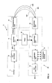
- Figure 4 shows an exemplary embodiment of a communication system according to the present invention. More specifically, the communication system comprises a transmitter 10 and a receiver 20 which communicate through a communication channel consisting of a plurality of diversity branches 40A, 40B and 40C. Although three diversity branches are illustrated in the figure, it becomes clear to a person skilled in the art that an arbitrary number of branches may be chosen.
- a data source 11 data packets are supplied to a FEC encoder 12, preferably a FEC Turbo encoder, where redundancy bits are added to correct errors.
- the bits output from the FEC encoder are subsequently supplied to a mapping unit 13 acting as a modulator to output symbols formed according to the applied modulation scheme stored as a constellation pattern in a table 15.
- the data symbols are applied to a transmission unit 30 for transmission over the branches 40A - C.
- the receiver 20 receives the data packets by the receiving unit 35.
- the bits are then input into a demapping unit 21 which acts as a demodulator using the same signal constellation pattern stored in the table 15 which was used during the modulation of that symbol.
- the demodulated data packets received over one diversity branch are stored in a temporary buffer 22 for subsequent combining in a combining unit 23 with the data packets received over at least one other diversity branch.
- table 15 stores a plurality of signal constellation patterns #0..#n which are selected for the individual transmissions over the individual diversity branches according to a predetermined scheme.
- the scheme i.e. the sequence of signal constellation patterns used for modulating/demodulating are either pre-stored in the transmitter and the receiver or are signalled by transmitter to the receiver prior to usage.
Abstract
Description
- The present invention relates generally to transmission techniques in wireless communication systems and in particular to a method, transceiver and receiver using transmit diversity schemes wherein the bit-to-symbol mapping is performed differently for different transmitted diversity branches. The invention is particularly applicable to systems with unreliable and time-varying channel conditions resulting in an improved performance avoiding transmission errors.
- There exist several well known transmit diversity techniques wherein one or several redundancy versions relating to identical data are transmitted on several (at least two) diversity branches "by default" without explicitly requesting (by a feedback channel) further diversity branches (as done in an ARQ scheme by requesting retransmissions).For example the following schemes are considered as transmit diversity:
- ■ Site Diversity: The transmitted signal originates from different sites, e.g. different base stations in a cellular environment.
- ■ Antenna Diversity: The transmitted signal originates from different antennas, e.g. different antennas of a multi-antenna base station.
- ■ Polarization Diversity: The transmitted signal is mapped onto different polarizations.
- ■ Frequency Diversity: The transmitted signal is mapped e.g. on different carrier frequencies or on different frequency hopping sequences.
- ■ Time Diversity: The transmitted signal is e.g. mapped on different interleaving sequences.
- ■ Multicode Diversity: The transmitted signal is mapped on different codes in e.g. a CDMA (Code Division Multiple Access) system.
- There are known several diversity combining techniques. The following three techniques are the most common ones:
- ■ Selection Combining: Selecting the diversity branch with the highest SNR for decoding, ignoring the remaining ones.
- ■ Equal Gain Combining: Combining received diversity branches with ignoring the differences in received SNR.
- ■ Maximal Ratio Combining: Combining received diversity branches taking the received SNR of each diversity branch into account. The combining can be performed at bit-level (e.g. LLR) or at modulation symbol level.
- Furthermore, a common technique for error detection/correction is based on Automatic Repeat reQuest (ARQ) schemes together with Forward Error Correction (FEC), called hybrid ARQ (HARQ). If an error is detected within a packet by the Cyclic Redundancy Check (CRC), the receiver requests the transmitter to send additional information (retransmission) to improve the probability to correctly decode the erroneous packet.
- In WO-02/067491 A1 a method for hybrid ARQ transmissions has been disclosed which averages the bit reliabilities over successively requested retransmissions by means of signal constellation rearrangement.
- As shown therein, when employing higher order modulation formats (e.g. M-PSK, M-QAM with log2(M) > 2), where more than 2 bits are mapped onto one modulation symbol, the bits mapped onto a modulation symbol have different reliabilities depending on their content and depending on the chosen mapping. This leads for most FEC (e.g. Turbo Codes) schemes to a degraded decoder performance compared to an input of more equally distributed bit reliabilities.
- In conventional communication systems the modulation dependent variations in bit reliabilities are not taken into account and, hence, usually the variations remain after combining the diversity branches at the receiver.
- The object of the invention is to provide a method, transmitter and receiver which show an improved performance with regard to transmission errors. This object is solved by a method, transmitter and receiver as set forth in the independent claims.
- The invention is based on the idea to improve the decoding performance at the receiver by applying different signal constellation mappings to the available distinguishable transmit diversity branches. The idea is applicable to modulation formats, where more than 2 bits are mapped onto one modulation symbol, since this implies a variation in reliabilities for the bits mapped onto the signal constellation (e.g. for regular BPSK and QPSK modulation all bits mapped onto a modulation symbol have the same reliability). The variations depend on the employed mapping and on the actually transmitted content of the bits.
- Depending on the employed modulation format and the actual number of bits mapped onto a single modulation symbol, for a given arbitrary number (N > 1) of available diversity branches the quality of the averaging process is different. Averaging in the sense of the present invention is understood as a process of reducing the differences in mean combined bit reliabilities among the different bits of a data symbol. Although it might be that only after using several diversity branches or paths a perfect averaging with no remaining differences is achieved, averaging means in the context of the document any process steps in the direction of reducing the mean combined bit reliability differences. Assuming on average an equal SNR for all available diversity branches, for 16-
QAM 4 mappings (4 diversity branches) would be needed to perfectly average out the reliabilities for all bits mapped on any symbol. However, if e.g. only 2 branches are available a perfect averaging is not possible. Hence, the averaging should then be performed on a best effort basis as shown in the example below. - The present invention will be more readily understood from the following detailed description of preferred embodiments with reference to the accompanying figures which show:
- FIG. 1
- an example for a 16-QAM signal constellation;
- FIG. 2
- an example for a different mapping of a 16-QAM signal constellation;
- FIG. 3
- two further examples of 16-QAM signal constellations;
- FIG. 4
- an exemplary embodiment of a communication system according to the present invention; and
- FIG. 5
- details of a table for storing a plurality of signal constellation patterns.
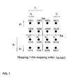
- The following detailed description is shown for a square 16-QAM with Gray mapping. However, without loss of generality the shown example is extendable to other M-QAM and M-PSK (with log2(M) > 2) formats. Moreover, the examples are shown for transmit diversity schemes transmitting an identical bit-sequence on both branches (single redundancy version scheme). Then again, an extension to a transmit diversity scheme transmitting only partly identical bits on the diversity branches can be accomplished. An example for a system using multiple redundancy versions is described in copending
EP 01127244, filed on November 16, 2001 - Assuming a transmit diversity scheme with two generated diversity branches, which are distinguishable at the receiver (e.g. by different spreading or scrambling codes in a CDMA system, or other techniques of creating orthogonal branches) and a transmission of the same redundancy version, usually the received diversity branches are combined at the receiver before applying the FEC decoder. A common combining technique is the maximal ratio combining, which can be achieved by adding the calculated log-likelihood-ratios LLRs from each individual received diversity branch.
- The log-likelihood-ratio LLR as a soft-metric for the reliability of a demodulated bit b from a received modulation symbol r = x + jy is defined as follows:

- As can be seen from Figure 1 (bars indicate rows/columns for which the respective bit equals 1), the mappings of the in-phase component bits and the quadrature component bits on the signal constellation are orthogonal (for M-PSK the LLR calculation cannot be simplified by separating into complex components, however the general procedure of bit-reliability averaging is similar). Therefore, it is sufficient to focus on the in-phase component bits i 1 and i 2. The same conclusions apply then for q 1 and q 2.
- Assuming that
Mapping 1 from Figure 1 is applied for the bit-to-symbol mapping for the 1st diversity branch, the log-likelihood-ratio LLR of the most significant bit (MSB) i 1 and the least significant bit (LSB) i 2 yields the following equations for a Gaussian channel:

where x denotes the in-phase component of the normalized received modulation symbol r and K is a factor proportional to the signal-to-noise ratio. Under the assumption of a uniform signal constellation (x1 = 3x0,regular 16-QAM) equations (2) and (3) can be fairly good approximated as shown in S. Le Goff, A. Glavieux, C. Berrou, "Turbo-Codes and High Spectral Efficiency Modulation," IEEE SUPERCOMM/ICC '94, Vol. 2 , pp. 645 -649 ,1994, and Ch. Wengerter, A. Golitschek Edler von Elbwart, E. Seidel, G. Velev, M.P. Schmitt, "Advanced Hybrid ARQ Technique Employing a Signal Constellation Rearrangement," IEEE Proceedings of VTC 2002 Fall, Vancouver, Canada, September 2002 by

- The mean LLR for i 1 and i 2 for a given transmitted modulation symbol yields the values given in Table 1 (substituting 4Kx 0 2 by A). Mean in this sense, refers to that the mean received value for a given transmitted constellation point, exactly matches this transmitted constellation point. Individual samples of course experience noise according to the parameter K. However, for a Gaussian channel the mean value of the noise process is zero. In case of transmitted modulation symbols 0q 11q 2 and 1q 11q2, where q1 and q2 are arbitrary, the magnitude of the mean LLR (i1) is higher than of the mean LLR (i2). This means that the LLR for the MSB i 1 depends on the content of the LSB i2; e.g. in Figure 1 i 1 has a higher mean reliability in case the logical value for i2 equals 1 (leftmost and rightmost columns). Hence, assuming a uniform distribution of transmitted modulation symbols, on average 50 % of the MSBs i 1 have about three times the magnitude in LLR of i2.
Table 1. Mean LLRs for bits mapped on the in-phase component of the signal constellation for Mapping 1 in Figure 1 according to equations (4) and (5).Symbol (i 1 q 1 i 2 q 2) Mean value of x Mean LLR (i 1) Mean LLR (i 2) 0q 10q 2 x 0 -4Kx0 2 = -Λ -4Kx0 2 = -Λ 0q 11q 2 x 1 -12Kx0 2 = - 3Λ 4Kx 02 = Λ 1 q10q2 -x0 4Kx0 2 = Λ -4Kx0 2 = -Λ 1q 11q 2 -x1 12Kx 0 2 = 3Λ 4Kx 0 2 = Λ - If now adding a 2nd transmit diversity branch transmitting e.g. an identical bit sequence prior art schemes would employ an identical mapping to the 1st diversity branch. Here, it is proposed to employ a 2nd signal constellation mapping (Mapping 2) according to Figure 2 (of course, also one of the constellations depicted in Figure 3 are possible), which yields the mean LLRs given in Table 2.
Table 2. Mean LLRs for bits mapped on the in-phase component of the signal constellation for Mapping 2 in Figure 2.Symbol (i1 q 1 i 2 q 2) Mean value of x Mean LLR (i 1) Mean LLR (i 2) 0q 10q 2 x 0 -Λ -3Λ 0q 11q 2 x 1 -Λ 3Λ 1q 10q 2 -x 0 Λ -Λ 1q 11q 2 -x 1 Λ Λ - Comparing now the soft-combined LLRs of the received diversity branches applying the constellation rearrangement (
Mapping 1+2) and applying the identical mappings (Mapping 1+1, prior art), it can be observed from table 3 that the combined mean LLR values with applying the constellation rearrangement have a more uniform distribution (Magnitudes: 4 x 4A and 4 x 2A instead of 2 x 6A and 6 x 2A). For most FEC decoders (e.g. Turbo Codes and Convolutional Codes) this leads to a better decoding performance. Investigations have revealed that in particular Turbo encoding/decoding systems exhibit a superior performance. It should be noted, that the chosen mappings are non exhaustive and more combinations of mappings fulfilling the same requirements can be found.Table 3. Mean LLRs (per branch) and combined mean LLRs for bits mapped on the in-phase component of the signal constellation for the diversity branches when employing Mapping times Mapping 1.Transmit Diversity Branch Symbol (i1q1i2q2) Constellation Rearrangement ( Mapping 1 +2)Prior Art No Rearrangement ( Mapping 1+1)Mean LLR (i 1) Mean LLR (i 2) Mean LLR (i 1) Mean LLR (i 2) 1 0q 10q 2 -Λ -Λ -Λ -Λ 0q 11q 2 -3Λ Λ -3Λ Λ 1q 10q 2 Λ -Λ Λ -Λ 1q11q2 3Λ Λ 3Λ Λ 2 0q 10q 2 -Λ -3Λ -Λ -Λ 0q 11q 2 -Λ 3Λ -3Λ Λ 1q 10q 2 Λ -Λ Λ -Λ 1q 11q 2 Λ Λ 3Λ Λ Combined 1+2 0q 10q 2 -2Λ -4Λ -2Λ -2Λ 0q 11q 2 -4Λ -4Λ -6Λ 2Λ 1q 1 q 2 2Λ -2Λ 2Λ -2Λ 1q 11q 2 4Λ 2Λ 6Λ 2Λ - In the following an example with 4 diversity branches will be described. Here, the same principles apply as for 2 diversity branches. However, since 4 diversity branches are available and the averaging with 2 diversity branches is not perfect, additional mappings can be used to improve the averaging process.
- Figure 3 shows the additional mappings for
diversity branches Mappings branches 1 and 2 (in Figure 1 and - Figure 2). Then the averaging can be performed perfectly and all bits mapped on any symbol will have an equal mean bit reliability (assuming the same SNR for all transmissions). Table 4 compares the LLRs with and without applying the proposed Constellation Rearrangement. Having a closer look at the combined LLRs, it can be seen that with application of the Constellation Rearrangement the magnitude for all bit reliabilities results in 6A.
- It should be noted again, that the chosen mappings are non exhaustive and more combinations of mappings fulfilling the same requirements can be found.
Table 4. Mean LLRs (per branch) and combined mean LLRs for bits mapped on the in-phase component of the signal constellation for the diversity branches when employing Mappings 1 to 4 and when employing 4times Mapping 1.Transmit Diversity Branch Symbol (i 1 q 1 i 2 q 2) Constellation Rearrangement ( Mapping 1 +2+3+4)Prior Art No Rearrangement ( Mapping 1 +1 +1 +1)Mean LLR (i1) Mean LLR (i 2) Mean LLR (i 1) Mean LLR (i 2) 1 0q 10q 2 -Λ -Λ -Λ -Λ 0q 11q 2 -3Λ Λ -3Λ Λ 1q 10q 2 Λ -Λ Λ -Λ 1q 11q 2 3Λ Λ 3Λ Λ 2 0q 10q 2 -Λ -3Λ -Λ -Λ 0q 11q 2 -Λ 3Λ -3Λ Λ 1 q 10q 2 Λ -Λ Λ -Λ 1q 11q 2 Λ Λ 3Λ Λ 3 0q 10q 2 -Λ -Λ -Λ -Λ 0q 11q 2 -Λ Λ -3Λ Λ 1q 10q 2 Λ -3Λ Λ -Λ 1q 11q 2 Λ 3Λ 3Λ Λ 4 0q 10q 2 -3Λ -Λ -Λ -Λ 0q 11q 2 -Λ Λ -3Λ Λ 1q 10q 2 3Λ -Λ Λ -Λ 1q 11q 2 Λ Λ 3Λ Λ Combined 1+2+3+4 0q 10q 2 -6Λ -6Λ -4Λ -4Λ 0q 11q2 -6Λ 6Λ -12Λ 4Λ 1q 10q 2 6Λ -6Λ 4Λ -4Λ 1q 11q 2 6Λ 6Λ 12Λ 4Λ - If the constellation rearrangement is performed by applying different mapping schemes, one would end up in employing a number of different mappings as given in Figure 1, Figure 2 and Figure 3. If the identical mapper (e.g. Figure 1) should be kept for all transmit diversity branches,
e.g. mapping 2 can be obtained frommapping 1 by the following operations: - ■ exchange positions of original bits i 1 and i 2
- ■ exchange positions of original bits q 1 and q 2
- ■ logical bit inversion of original bits i 1 and q 1
- Alternatively, those bits that end in
positions - Therefore, the following table provides an example how to obtain
mappings 1 to 4 (or mappings with equivalent bit reliabilities for i 1 , i2, q1 and q 2), where the bits always refer to the first transmission, and a long dash above a character denotes logical bit inversion of that bit:Table 5. Alternative implementation of the Constellation Rearrangement by interleaving (intra-symbol interleaving) and logical inversion of bits mapped onto the modulation symbols. Mapping No. Interleaver and Inverter functionality 1 i 1 q 1 i 2 q 2 2 i̅ 2 q̅ 2 i̅ 1 q̅ 1 or i 2 q 2i̅1 q̅ 1 3 i̅ 2 q̅ 2 i 1 q 1 or i 2 q 2 i 1 q 1 4 i 1 q 1 i̅ 2 q̅ 2 or i̅ 1 q̅ 1 i̅ 2q̅2 - Generally at least 2 different mappings should be employed for N > 1 diversity branches, where the order and the selection of the mappings is irrelevant, as long as the bit-reliability averaging process, meaning the (reduction of differences in reliabilities) is maintained.
- Preferred realizations in terms of number of employed mappings
- o M-QAM
- ■ Employing log2(M) different mappings
- ■ Employing log2(M)/2 different mappings
- o M-PSK
- ■ Employing log2(M) different mappings
- ■ Employing log2(M)/2 different mappings
- ■ Employing 2log2(M) different mappings
- The applied signal constellation mappings for modulation at the transmitter and demodulation at the receiver need to match for each individual transmit diversity branch. This can be achieved by appropriate signalling of parameters indicating the proper mapping or combination of mappings to be applied for the diversity branches. Alternatively the definition of the mappings to be applied for transmit diversity branches may be system predefined.
- Figure 4 shows an exemplary embodiment of a communication system according to the present invention. More specifically, the communication system comprises a
transmitter 10 and areceiver 20 which communicate through a communication channel consisting of a plurality ofdiversity branches data source 11, data packets are supplied to aFEC encoder 12, preferably a FEC Turbo encoder, where redundancy bits are added to correct errors. The bits output from the FEC encoder are subsequently supplied to amapping unit 13 acting as a modulator to output symbols formed according to the applied modulation scheme stored as a constellation pattern in a table 15. Subsequently the data symbols are applied to atransmission unit 30 for transmission over thebranches 40A - C. Thereceiver 20 receives the data packets by the receivingunit 35. The bits are then input into ademapping unit 21 which acts as a demodulator using the same signal constellation pattern stored in the table 15 which was used during the modulation of that symbol. - The demodulated data packets received over one diversity branch are stored in a
temporary buffer 22 for subsequent combining in a combiningunit 23 with the data packets received over at least one other diversity branch. - As illustrated in figure 5, table 15 stores a plurality of signal
constellation patterns # 0..#n which are selected for the individual transmissions over the individual diversity branches according to a predetermined scheme. The scheme, i.e. the sequence of signal constellation patterns used for modulating/demodulating are either pre-stored in the transmitter and the receiver or are signalled by transmitter to the receiver prior to usage.
Claims (21)
- A method of transmitting data in a wireless communication system from a transmitter to a receiver, comprising the steps of
modulating data at the transmitter using a first signal constellation pattern to obtain a first data symbol,
transmitting the first data symbol to the receiver over a first diversity branch;
modulating said data at the transmitter using a second signal constellation pattern to obtain a second data symbol;
transmitting the second data symbol to the receiver over a second diversity branch;
demodulating the received first and second data symbol at the receiver using the first and respectively second signal constellation pattern; and
diversity combining the demodulated data. - The method according to claim 1, wherein the data to be transmitted contains at least one data packet comprising a plurality of data bits which are encoded using a forward error correction (FEC) scheme prior to modulation.
- The method according to claim 2, wherein employed encoding scheme is a Turbo coding scheme.
- The method according to one of claims 1 or 3, wherein the employed modulation scheme is a higher order modulation scheme such as M-PSK, M-QAM with log2 (M) > 2 wherein the data bits mapped onto the data symbols have different bit reliabilities depending on the chosen mapping.
- The method according to one of claims 1 to 4, wherein the signal constellation pattern for the first and second diversity branches are selected such that after combining the data bits, the differences in magnitude among the combined bit reliabilities are reduced.
- The method according to one of claims 1 to 5, wherein the number of different mappings is equal to log2(M).
- The method according to one of claims 1 to 6, wherein the data for transmission is modulated using a single redundancy version scheme with an identical data bit sequence.
- The method according to one of claims 1 to 7, wherein the data for transmission is modulated using a multiple redundancy version scheme of partly identical bits.
- The method according to one of claims 1 to 8, wherein the first and second signal constellation patterns are pre-stored in a memory table.
- The method according to one of claims 1 to 9, wherein the first and second signal constellation patterns are signaled to the receiver.
- The method according to one of claims 1 to 10, wherein the properties of the first and second signal constellation patterns are obtained by interleaving the positions of and/or inverting the bit values of the bits mapped onto the signal constellation patterns.
- The method according to one of claims 1 to 11, wherein the interleaving is performed with symbols resulting in an intra-symbol interleaving.
- The method according to one of claims 1 to 12, wherein the data is transmitted with a plurality of redundancy versions, and the transmitted bits comprise systematic and parity bits and the systematic bits are included in each redundancy version.
- The method according to one of claims 1 to 13, wherein the combined mean bit reliabilities for the systematic bits are higher than that of the parity bits.
- A transmitter for transmitting data in a wireless communication system to a receiver, comprising:a mapping unit for modulating data using a first signal constellation pattern to obtain a first data symbol;a transmitting unit for transmitting the first data symbol to the receiver using a first diversity branch;said mapping unit modulating said data using a second signal constellation pattern to obtain a second data symbol; andsaid transmitting unit transmitting the second data symbol to the receiver using a second diversity branch.
- The transmitter according to claim 15, further comprising table means for prestoring the first and second signal constellation pattern.
- The transmitter according to claim 15, further comprising an interleaver and/or inverter to obtain different signal constellation patterns.
- The transmitter according to one of claims 15 to 17, further comprising a forward error correction (FEC) encoder for encoding the data prior to modulation.
- A receiver as part of a wireless communication system, comprising:receiving means for receiving a first and second data symbol respectively modulated using a first and second signal constellation pattern and transmitted over a first and second diversity branch, anda demapping unit for demodulating the received first and second data symbol using the first and second constellation pattern respectively,a combining unit for diversity combining the received data symbols.
- The receiver according to claim 19, further comprising a memory means for storing received data prior to combining same.
- The receiver according to claim 19 or 20, further comprising a forward error correction (FEC) decoder for decoding the combined first and second data after diversity combining.
Priority Applications (2)
| Application Number | Priority Date | Filing Date | Title |
|---|---|---|---|
| DE60234792T DE60234792D1 (en) | 2002-10-18 | 2002-10-18 | Constellation reorganization for broadcast diversity types |
| EP09165063.0A EP2110978B1 (en) | 2002-10-18 | 2002-10-18 | Constellation rearrangement for transmit diversity schemes |
Applications Claiming Priority (2)
| Application Number | Priority Date | Filing Date | Title |
|---|---|---|---|
| EP02774730A EP1552637B1 (en) | 2002-10-18 | 2002-10-18 | Constellation rearrangement for transmit diversity schemes |
| PCT/EP2002/011695 WO2004036817A1 (en) | 2002-10-18 | 2002-10-18 | Constellation rearrangement for transmit diversity schemes |
Related Parent Applications (1)
| Application Number | Title | Priority Date | Filing Date |
|---|---|---|---|
| EP02774730A Division EP1552637B1 (en) | 2002-10-18 | 2002-10-18 | Constellation rearrangement for transmit diversity schemes |
Related Child Applications (1)
| Application Number | Title | Priority Date | Filing Date |
|---|---|---|---|
| EP09165063.0A Division EP2110978B1 (en) | 2002-10-18 | 2002-10-18 | Constellation rearrangement for transmit diversity schemes |
Publications (3)
| Publication Number | Publication Date |
|---|---|
| EP1858189A2 true EP1858189A2 (en) | 2007-11-21 |
| EP1858189A3 EP1858189A3 (en) | 2008-03-19 |
| EP1858189B1 EP1858189B1 (en) | 2009-12-16 |
Family
ID=32103875
Family Applications (3)
| Application Number | Title | Priority Date | Filing Date |
|---|---|---|---|
| EP09165063.0A Expired - Lifetime EP2110978B1 (en) | 2002-10-18 | 2002-10-18 | Constellation rearrangement for transmit diversity schemes |
| EP07013714A Expired - Lifetime EP1858189B1 (en) | 2002-10-18 | 2002-10-18 | Constellation rearrangement for transmit diversity schemes |
| EP02774730A Expired - Lifetime EP1552637B1 (en) | 2002-10-18 | 2002-10-18 | Constellation rearrangement for transmit diversity schemes |
Family Applications Before (1)
| Application Number | Title | Priority Date | Filing Date |
|---|---|---|---|
| EP09165063.0A Expired - Lifetime EP2110978B1 (en) | 2002-10-18 | 2002-10-18 | Constellation rearrangement for transmit diversity schemes |
Family Applications After (1)
| Application Number | Title | Priority Date | Filing Date |
|---|---|---|---|
| EP02774730A Expired - Lifetime EP1552637B1 (en) | 2002-10-18 | 2002-10-18 | Constellation rearrangement for transmit diversity schemes |
Country Status (9)
| Country | Link |
|---|---|
| US (4) | US7164727B2 (en) |
| EP (3) | EP2110978B1 (en) |
| JP (1) | JP3885079B2 (en) |
| KR (1) | KR100636947B1 (en) |
| CN (1) | CN1301603C (en) |
| AT (2) | ATE367689T1 (en) |
| AU (1) | AU2002340580A1 (en) |
| DE (2) | DE60234792D1 (en) |
| WO (1) | WO2004036817A1 (en) |
Families Citing this family (30)
| Publication number | Priority date | Publication date | Assignee | Title |
|---|---|---|---|---|
| WO2004036817A1 (en) * | 2002-10-18 | 2004-04-29 | Matsushita Electric Industrial Co., Ltd. | Constellation rearrangement for transmit diversity schemes |
| US7925953B2 (en) * | 2003-10-07 | 2011-04-12 | Nokia Corporation | Redundancy strategy selection scheme |
| WO2005109710A1 (en) | 2004-05-11 | 2005-11-17 | Matsushita Electric Industrial Co., Ltd. | Radio transmitter apparatus, radio receiver apparatus, and wireless communication system |
| US7281174B1 (en) * | 2004-10-01 | 2007-10-09 | Rockwell Collins, Inc. | Diversity code combining scheme for turbo coded systems |
| EP1655878A1 (en) | 2004-11-03 | 2006-05-10 | Matsushita Electric Industrial Co., Ltd. | Method and transmitter structure reducing ambiguity by repetition rearrangement in the symbol domain |
| WO2006048061A1 (en) * | 2004-11-03 | 2006-05-11 | Matsushita Electric Industrial Co., Ltd. | Method and transmitter structure removing phase ambiguity by repetition rearrangement |
| EP1655877A1 (en) | 2004-11-03 | 2006-05-10 | Matsushita Electric Industrial Co., Ltd. | Method and transmitter structure reducing ambiguity by repetition rearrangement in the bit domain |
| DE602005012440D1 (en) * | 2005-04-28 | 2009-03-05 | Panasonic Corp | REPEAT-DEPENDENT ILLUSTRATION FOR HIGH-ORDER MODULATION PROCEDURES |
| CN101218773B (en) * | 2005-05-04 | 2012-08-29 | 松下电器产业株式会社 | Signal space expansion method and device for 16 QAM scheme |
| EP1878188B1 (en) | 2005-05-04 | 2009-09-16 | Panasonic Corporation | Data transmissions in a mobile communication system employing diversity and constellation rearrangement of a 16 qam scheme |
| CN100420177C (en) * | 2005-06-27 | 2008-09-17 | 华为技术有限公司 | Mixed automatic retransmitting method |
| EP1897316B1 (en) | 2005-06-29 | 2014-11-26 | Panasonic Intellectual Property Corporation of America | Method for using a symbol mapper using a symbol mapping scheme to generate modulation symbols according to a different symbol mapping scheme and a method for generating a symbol mapping scheme |
| US20070005248A1 (en) * | 2005-06-29 | 2007-01-04 | Intel Corporation | Data reconstruction in link-based interconnects |
| ATE553580T1 (en) | 2005-07-26 | 2012-04-15 | Panasonic Corp | BIT-POWERED REORDER DIVERSITY FOR AICO IMAGE |
| EP1938538B1 (en) * | 2005-08-19 | 2019-10-23 | Samsung Electronics Co., Ltd. | Method for variable sub-carrier mapping and device using the same |
| KR101287272B1 (en) | 2006-08-07 | 2013-07-17 | 엘지전자 주식회사 | data transmission method and hybrid automatic repeat request method using adaptive mapper |
| CN101272526B (en) * | 2007-03-22 | 2012-07-04 | 华为技术有限公司 | Service data transmission method, communication system, base station and user device |
| US7925783B2 (en) * | 2007-05-23 | 2011-04-12 | Microsoft Corporation | Transparent envelope for XML messages |
| WO2009031805A2 (en) * | 2007-09-05 | 2009-03-12 | Lg Electronics Inc. | Method of transmitting and receiving a signal and apparatus for transmitting and receiving a signal |
| CN101471757B (en) * | 2007-12-25 | 2013-06-05 | 华为技术有限公司 | Reception and coalition method, system and equipment |
| CN101483463B (en) * | 2008-01-11 | 2013-06-05 | 华为技术有限公司 | Data sending method and apparatus based on multi-diversity |
| DE102008039051A1 (en) | 2008-08-21 | 2010-02-25 | Audi Ag | Method of obtaining images in multiple reception |
| JP5327808B2 (en) * | 2009-11-18 | 2013-10-30 | 国立大学法人東京工業大学 | IDMA receiver |
| CN102148797B (en) * | 2010-02-08 | 2014-02-12 | 上海贝尔股份有限公司 | Combined multiple data stream transmission technology |
| KR101199781B1 (en) * | 2010-08-03 | 2012-11-12 | (주)에프씨아이 | Detection method of data transfer error using periodic pattern data |
| WO2017213564A1 (en) | 2016-06-09 | 2017-12-14 | Telefonaktiebolaget Lm Ericsson (Publ) | Packet modulation and coding suitable for broadcasting using hierarchical modulation and unequal error protection |
| TWI625955B (en) * | 2016-10-12 | 2018-06-01 | 國立清華大學 | Cooperative multimedia communication method and system thereof |
| TW202310595A (en) * | 2019-01-09 | 2023-03-01 | 美商Idac控股公司 | Methods and apparatuses for reliable multi-transmission systems |
| WO2020170316A1 (en) * | 2019-02-18 | 2020-08-27 | 学校法人玉川学園 | Information processing device |
| CN110730059B (en) * | 2019-10-21 | 2022-03-29 | 深圳智微电子科技有限公司 | Diversity copy receiving performance optimization method |
Citations (2)
| Publication number | Priority date | Publication date | Assignee | Title |
|---|---|---|---|---|
| EP1096718A2 (en) | 1999-10-28 | 2001-05-02 | Lucent Technologies Inc. | Data transmission with diversity, using several modulation schemes |
| US20020036980A1 (en) | 1999-04-15 | 2002-03-28 | Lundby Stein S. | Interleaver and deinterleaver for use in a diversity transmission communication system |
Family Cites Families (28)
| Publication number | Priority date | Publication date | Assignee | Title |
|---|---|---|---|---|
| US5583889A (en) * | 1994-07-08 | 1996-12-10 | Zenith Electronics Corporation | Trellis coded modulation system for HDTV |
| US5689439A (en) | 1995-03-31 | 1997-11-18 | Lucent Technologies, Inc. | Switched antenna diversity transmission method and system |
| US7180955B2 (en) * | 2000-08-22 | 2007-02-20 | Texas Instruments Incorporated | Parallel concatenated trellis-coded modulation with asymmetric signal mapping |
| JP4034824B2 (en) * | 1996-04-26 | 2008-01-16 | エイ・ティ・アンド・ティ・コーポレーション | Method and apparatus for data transmission using multiple transmit antennas |
| US5914959A (en) * | 1996-10-31 | 1999-06-22 | Glenayre Electronics, Inc. | Digital communications system having an automatically selectable transmission rate |
| US6134273A (en) * | 1996-12-23 | 2000-10-17 | Texas Instruments Incorporated | Bit loading and rate adaptation on DMT DSL data transmission |
| AU736233B2 (en) * | 1997-06-13 | 2001-07-26 | Lucent Technologies Inc. | Multilevel coding with time diversity |
| US6208663B1 (en) * | 1997-08-29 | 2001-03-27 | Telefonaktiebolaget Lm Ericsson (Publ) | Method and system for block ARQ with reselection of FEC coding and/or modulation |
| FI105734B (en) * | 1998-07-03 | 2000-09-29 | Nokia Networks Oy | Automatic retransmission |
| EP0998045A1 (en) * | 1998-10-30 | 2000-05-03 | Lucent Technologies Inc. | Digital transmission system and method |
| US6285034B1 (en) | 1998-11-04 | 2001-09-04 | James L. Hanna | Inspection system for flanged bolts |
| US6891897B1 (en) * | 1999-07-23 | 2005-05-10 | Nortel Networks Limited | Space-time coding and channel estimation scheme, arrangement and method |
| US7173978B2 (en) * | 2000-07-21 | 2007-02-06 | Song Zhang | Method and system for turbo encoding in ADSL |
| US6476734B2 (en) * | 2000-09-14 | 2002-11-05 | Texas Instruments Incorporated | Method and apparatus for prioritizing information protection in high order modulation symbol mapping |
| DE60033198T2 (en) * | 2000-11-22 | 2007-05-03 | Nortel Networks Ltd., St. Laurent | METHOD AND DEVICE FOR TURBO ROOM-TIME TRELLISCODING |
| DE60102296T2 (en) * | 2001-02-21 | 2004-07-29 | Matsushita Electric Industrial Co., Ltd., Kadoma | HYBRID ARQ METHOD WITH REORGANIZATION OF SIGNAL CONSTELLATION |
| US7133459B2 (en) * | 2001-05-01 | 2006-11-07 | Texas Instruments Incorporated | Space-time transmit diversity |
| US7778355B2 (en) * | 2001-05-01 | 2010-08-17 | Texas Instruments Incorporated | Space-time transmit diversity |
| US20030012315A1 (en) * | 2001-07-06 | 2003-01-16 | John Fan | System and method for multistage error correction coding wirelessly transmitted information in a multiple antennae communication system |
| KR100464346B1 (en) * | 2001-08-17 | 2005-01-03 | 삼성전자주식회사 | Transmission/reception apparatus and method for packet retransmission in a cdma mobile communication system |
| US6738370B2 (en) * | 2001-08-22 | 2004-05-18 | Nokia Corporation | Method and apparatus implementing retransmission in a communication system providing H-ARQ |
| KR100464325B1 (en) * | 2001-10-15 | 2005-01-03 | 삼성전자주식회사 | Method and apparatus for transmitting/receiving for re-transmission of packet in mobile communication system |
| EP1313248B1 (en) * | 2001-11-16 | 2005-08-31 | Matsushita Electric Industrial Co., Ltd. | Hybrid ARQ method for packet data transmission |
| DE60114849T2 (en) * | 2001-11-16 | 2006-04-20 | Matsushita Electric Industrial Co., Ltd., Kadoma | ARQ retransmission with request repeating scheme that uses multiple redundancy versions and receiver / sender for it |
| US7095812B2 (en) * | 2002-06-24 | 2006-08-22 | Agere Systems Inc. | Reduced complexity receiver for space-time- bit-interleaved coded modulation |
| US7095709B2 (en) * | 2002-06-24 | 2006-08-22 | Qualcomm, Incorporated | Diversity transmission modes for MIMO OFDM communication systems |
| WO2004036817A1 (en) * | 2002-10-18 | 2004-04-29 | Matsushita Electric Industrial Co., Ltd. | Constellation rearrangement for transmit diversity schemes |
| US8369449B2 (en) * | 2005-09-20 | 2013-02-05 | Koninklijke Philips Electronics N.V. | Method and system of diversity transmission of data employing M-point QAM modulation |
-
2002
- 2002-10-18 WO PCT/EP2002/011695 patent/WO2004036817A1/en active IP Right Grant
- 2002-10-18 DE DE60234792T patent/DE60234792D1/en not_active Expired - Lifetime
- 2002-10-18 EP EP09165063.0A patent/EP2110978B1/en not_active Expired - Lifetime
- 2002-10-18 DE DE60221297T patent/DE60221297T2/en not_active Expired - Lifetime
- 2002-10-18 US US10/501,905 patent/US7164727B2/en not_active Expired - Lifetime
- 2002-10-18 AU AU2002340580A patent/AU2002340580A1/en not_active Abandoned
- 2002-10-18 AT AT02774730T patent/ATE367689T1/en not_active IP Right Cessation
- 2002-10-18 EP EP07013714A patent/EP1858189B1/en not_active Expired - Lifetime
- 2002-10-18 KR KR1020047012009A patent/KR100636947B1/en active IP Right Grant
- 2002-10-18 CN CNB028280822A patent/CN1301603C/en not_active Expired - Lifetime
- 2002-10-18 AT AT07013714T patent/ATE452478T1/en not_active IP Right Cessation
- 2002-10-18 JP JP2004543996A patent/JP3885079B2/en not_active Expired - Lifetime
- 2002-10-18 EP EP02774730A patent/EP1552637B1/en not_active Expired - Lifetime
-
2006
- 2006-12-06 US US11/634,127 patent/US7558331B2/en not_active Expired - Lifetime
-
2009
- 2009-06-12 US US12/484,060 patent/US8005163B2/en not_active Expired - Fee Related
-
2011
- 2011-07-14 US US13/182,929 patent/US8675774B2/en not_active Expired - Lifetime
Patent Citations (2)
| Publication number | Priority date | Publication date | Assignee | Title |
|---|---|---|---|---|
| US20020036980A1 (en) | 1999-04-15 | 2002-03-28 | Lundby Stein S. | Interleaver and deinterleaver for use in a diversity transmission communication system |
| EP1096718A2 (en) | 1999-10-28 | 2001-05-02 | Lucent Technologies Inc. | Data transmission with diversity, using several modulation schemes |
Also Published As
| Publication number | Publication date |
|---|---|
| EP1552637B1 (en) | 2007-07-18 |
| DE60221297D1 (en) | 2007-08-30 |
| KR20040079435A (en) | 2004-09-14 |
| US20090245407A1 (en) | 2009-10-01 |
| AU2002340580A1 (en) | 2004-05-04 |
| EP2110978A2 (en) | 2009-10-21 |
| US7164727B2 (en) | 2007-01-16 |
| EP1858189B1 (en) | 2009-12-16 |
| US8675774B2 (en) | 2014-03-18 |
| ATE452478T1 (en) | 2010-01-15 |
| JP3885079B2 (en) | 2007-02-21 |
| EP1552637A1 (en) | 2005-07-13 |
| US20110274195A1 (en) | 2011-11-10 |
| WO2004036817A1 (en) | 2004-04-29 |
| US7558331B2 (en) | 2009-07-07 |
| JP2005533462A (en) | 2005-11-04 |
| EP2110978A3 (en) | 2010-11-03 |
| ATE367689T1 (en) | 2007-08-15 |
| DE60221297T2 (en) | 2007-10-31 |
| EP1858189A3 (en) | 2008-03-19 |
| US8005163B2 (en) | 2011-08-23 |
| US20050163040A1 (en) | 2005-07-28 |
| DE60234792D1 (en) | 2010-01-28 |
| KR100636947B1 (en) | 2006-10-19 |
| CN1620775A (en) | 2005-05-25 |
| EP2110978B1 (en) | 2014-01-01 |
| US20070140373A1 (en) | 2007-06-21 |
| CN1301603C (en) | 2007-02-21 |
Similar Documents
| Publication | Publication Date | Title |
|---|---|---|
| EP1552639B1 (en) | Constellation rearrangement for arq transmit diversity schemes | |
| EP1858189B1 (en) | Constellation rearrangement for transmit diversity schemes | |
| EP1571774B1 (en) | ARQ retransmission method with bit reordering scheme employing multiple redundancy versions and receiver/transmitter therefor | |
| US7289567B2 (en) | Apparatus and method for transmitting and receiving data using partial chase combining | |
| FI127323B (en) | Transmitter receiver device and method for retransmitting packets in a mobile communication system | |
| US20070002969A1 (en) | Transmitting/receiving apparatus and method in a mobile communication system | |
| US20060195756A1 (en) | Radio transmitter apparatus, radio receiver apparatus, and radio transmission method | |
| EP2259478A1 (en) | Constellation rearrangement for ARQ transmit diversity schemes | |
| GB2391778A (en) | Retransmission system in which bits are inverted and/or the mapping of bits to symbols is rearranged, depending on the number of previous retransmissions | |
| EP1760928B1 (en) | Hybrid ARQ method with mapping rearrangement of the signals constellation |
Legal Events
| Date | Code | Title | Description |
|---|---|---|---|
| PUAI | Public reference made under article 153(3) epc to a published international application that has entered the european phase |
Free format text: ORIGINAL CODE: 0009012 |
|
| AC | Divisional application: reference to earlier application |
Ref document number: 1552637 Country of ref document: EP Kind code of ref document: P |
|
| AK | Designated contracting states |
Kind code of ref document: A2 Designated state(s): AT BE BG CH CY CZ DE DK EE ES FI FR GB GR IE IT LI LU MC NL PT SE SK TR |
|
| AX | Request for extension of the european patent |
Extension state: AL LT LV MK RO SI |
|
| PUAL | Search report despatched |
Free format text: ORIGINAL CODE: 0009013 |
|
| AK | Designated contracting states |
Kind code of ref document: A3 Designated state(s): AT BE BG CH CY CZ DE DK EE ES FI FR GB GR IE IT LI LU MC NL PT SE SK TR |
|
| AX | Request for extension of the european patent |
Extension state: AL LT LV MK RO SI |
|
| 17P | Request for examination filed |
Effective date: 20080901 |
|
| 17Q | First examination report despatched |
Effective date: 20081009 |
|
| RAP1 | Party data changed (applicant data changed or rights of an application transferred) |
Owner name: PANASONIC CORPORATION |
|
| AKX | Designation fees paid |
Designated state(s): AT BE BG CH CY CZ DE DK EE ES FI FR GB GR IE IT LI LU MC NL PT SE SK TR |
|
| GRAP | Despatch of communication of intention to grant a patent |
Free format text: ORIGINAL CODE: EPIDOSNIGR1 |
|
| GRAS | Grant fee paid |
Free format text: ORIGINAL CODE: EPIDOSNIGR3 |
|
| GRAA | (expected) grant |
Free format text: ORIGINAL CODE: 0009210 |
|
| AC | Divisional application: reference to earlier application |
Ref document number: 1552637 Country of ref document: EP Kind code of ref document: P |
|
| AK | Designated contracting states |
Kind code of ref document: B1 Designated state(s): AT BE BG CH CY CZ DE DK EE ES FI FR GB GR IE IT LI LU MC NL PT SE SK TR |
|
| REG | Reference to a national code |
Ref country code: GB Ref legal event code: FG4D |
|
| REG | Reference to a national code |
Ref country code: CH Ref legal event code: EP |
|
| REG | Reference to a national code |
Ref country code: IE Ref legal event code: FG4D |
|
| REF | Corresponds to: |
Ref document number: 60234792 Country of ref document: DE Date of ref document: 20100128 Kind code of ref document: P |
|
| REG | Reference to a national code |
Ref country code: NL Ref legal event code: VDEP Effective date: 20091216 |
|
| PG25 | Lapsed in a contracting state [announced via postgrant information from national office to epo] |
Ref country code: SE Free format text: LAPSE BECAUSE OF FAILURE TO SUBMIT A TRANSLATION OF THE DESCRIPTION OR TO PAY THE FEE WITHIN THE PRESCRIBED TIME-LIMIT Effective date: 20091216 Ref country code: FI Free format text: LAPSE BECAUSE OF FAILURE TO SUBMIT A TRANSLATION OF THE DESCRIPTION OR TO PAY THE FEE WITHIN THE PRESCRIBED TIME-LIMIT Effective date: 20091216 |
|
| PG25 | Lapsed in a contracting state [announced via postgrant information from national office to epo] |
Ref country code: AT Free format text: LAPSE BECAUSE OF FAILURE TO SUBMIT A TRANSLATION OF THE DESCRIPTION OR TO PAY THE FEE WITHIN THE PRESCRIBED TIME-LIMIT Effective date: 20091216 |
|
| PG25 | Lapsed in a contracting state [announced via postgrant information from national office to epo] |
Ref country code: BG Free format text: LAPSE BECAUSE OF FAILURE TO SUBMIT A TRANSLATION OF THE DESCRIPTION OR TO PAY THE FEE WITHIN THE PRESCRIBED TIME-LIMIT Effective date: 20100316 Ref country code: EE Free format text: LAPSE BECAUSE OF FAILURE TO SUBMIT A TRANSLATION OF THE DESCRIPTION OR TO PAY THE FEE WITHIN THE PRESCRIBED TIME-LIMIT Effective date: 20091216 Ref country code: NL Free format text: LAPSE BECAUSE OF FAILURE TO SUBMIT A TRANSLATION OF THE DESCRIPTION OR TO PAY THE FEE WITHIN THE PRESCRIBED TIME-LIMIT Effective date: 20091216 Ref country code: PT Free format text: LAPSE BECAUSE OF FAILURE TO SUBMIT A TRANSLATION OF THE DESCRIPTION OR TO PAY THE FEE WITHIN THE PRESCRIBED TIME-LIMIT Effective date: 20100416 Ref country code: ES Free format text: LAPSE BECAUSE OF FAILURE TO SUBMIT A TRANSLATION OF THE DESCRIPTION OR TO PAY THE FEE WITHIN THE PRESCRIBED TIME-LIMIT Effective date: 20100327 |
|
| PG25 | Lapsed in a contracting state [announced via postgrant information from national office to epo] |
Ref country code: SK Free format text: LAPSE BECAUSE OF FAILURE TO SUBMIT A TRANSLATION OF THE DESCRIPTION OR TO PAY THE FEE WITHIN THE PRESCRIBED TIME-LIMIT Effective date: 20091216 Ref country code: CZ Free format text: LAPSE BECAUSE OF FAILURE TO SUBMIT A TRANSLATION OF THE DESCRIPTION OR TO PAY THE FEE WITHIN THE PRESCRIBED TIME-LIMIT Effective date: 20091216 Ref country code: BE Free format text: LAPSE BECAUSE OF FAILURE TO SUBMIT A TRANSLATION OF THE DESCRIPTION OR TO PAY THE FEE WITHIN THE PRESCRIBED TIME-LIMIT Effective date: 20091216 |
|
| PLBE | No opposition filed within time limit |
Free format text: ORIGINAL CODE: 0009261 |
|
| STAA | Information on the status of an ep patent application or granted ep patent |
Free format text: STATUS: NO OPPOSITION FILED WITHIN TIME LIMIT |
|
| PG25 | Lapsed in a contracting state [announced via postgrant information from national office to epo] |
Ref country code: CY Free format text: LAPSE BECAUSE OF FAILURE TO SUBMIT A TRANSLATION OF THE DESCRIPTION OR TO PAY THE FEE WITHIN THE PRESCRIBED TIME-LIMIT Effective date: 20091216 Ref country code: GR Free format text: LAPSE BECAUSE OF FAILURE TO SUBMIT A TRANSLATION OF THE DESCRIPTION OR TO PAY THE FEE WITHIN THE PRESCRIBED TIME-LIMIT Effective date: 20100317 |
|
| 26N | No opposition filed |
Effective date: 20100917 |
|
| PG25 | Lapsed in a contracting state [announced via postgrant information from national office to epo] |
Ref country code: DK Free format text: LAPSE BECAUSE OF FAILURE TO SUBMIT A TRANSLATION OF THE DESCRIPTION OR TO PAY THE FEE WITHIN THE PRESCRIBED TIME-LIMIT Effective date: 20091216 |
|
| PG25 | Lapsed in a contracting state [announced via postgrant information from national office to epo] |
Ref country code: IT Free format text: LAPSE BECAUSE OF FAILURE TO SUBMIT A TRANSLATION OF THE DESCRIPTION OR TO PAY THE FEE WITHIN THE PRESCRIBED TIME-LIMIT Effective date: 20091216 |
|
| PG25 | Lapsed in a contracting state [announced via postgrant information from national office to epo] |
Ref country code: MC Free format text: LAPSE BECAUSE OF NON-PAYMENT OF DUE FEES Effective date: 20101031 |
|
| REG | Reference to a national code |
Ref country code: CH Ref legal event code: PL |
|
| PG25 | Lapsed in a contracting state [announced via postgrant information from national office to epo] |
Ref country code: CH Free format text: LAPSE BECAUSE OF NON-PAYMENT OF DUE FEES Effective date: 20101031 Ref country code: LI Free format text: LAPSE BECAUSE OF NON-PAYMENT OF DUE FEES Effective date: 20101031 |
|
| PG25 | Lapsed in a contracting state [announced via postgrant information from national office to epo] |
Ref country code: IE Free format text: LAPSE BECAUSE OF NON-PAYMENT OF DUE FEES Effective date: 20101018 |
|
| PG25 | Lapsed in a contracting state [announced via postgrant information from national office to epo] |
Ref country code: LU Free format text: LAPSE BECAUSE OF NON-PAYMENT OF DUE FEES Effective date: 20101018 |
|
| PG25 | Lapsed in a contracting state [announced via postgrant information from national office to epo] |
Ref country code: TR Free format text: LAPSE BECAUSE OF FAILURE TO SUBMIT A TRANSLATION OF THE DESCRIPTION OR TO PAY THE FEE WITHIN THE PRESCRIBED TIME-LIMIT Effective date: 20091216 |
|
| REG | Reference to a national code |
Ref country code: GB Ref legal event code: 732E Free format text: REGISTERED BETWEEN 20140612 AND 20140618 |
|
| REG | Reference to a national code |
Ref country code: DE Ref legal event code: R082 Ref document number: 60234792 Country of ref document: DE Representative=s name: GRUENECKER, KINKELDEY, STOCKMAIR & SCHWANHAEUS, DE |
|
| REG | Reference to a national code |
Ref country code: DE Ref legal event code: R082 Ref document number: 60234792 Country of ref document: DE Representative=s name: GRUENECKER, KINKELDEY, STOCKMAIR & SCHWANHAEUS, DE Effective date: 20140711 Ref country code: DE Ref legal event code: R081 Ref document number: 60234792 Country of ref document: DE Owner name: PANASONIC INTELLECTUAL PROPERTY CORPORATION OF, US Free format text: FORMER OWNER: PANASONIC CORPORATION, KADOMA-SHI, OSAKA, JP Effective date: 20140711 Ref country code: DE Ref legal event code: R082 Ref document number: 60234792 Country of ref document: DE Representative=s name: GRUENECKER PATENT- UND RECHTSANWAELTE PARTG MB, DE Effective date: 20140711 |
|
| REG | Reference to a national code |
Ref country code: FR Ref legal event code: TP Owner name: PANASONIC INTELLECTUAL PROPERTY CORPORATION OF, US Effective date: 20140722 |
|
| REG | Reference to a national code |
Ref country code: FR Ref legal event code: PLFP Year of fee payment: 15 |
|
| REG | Reference to a national code |
Ref country code: FR Ref legal event code: PLFP Year of fee payment: 16 |
|
| REG | Reference to a national code |
Ref country code: FR Ref legal event code: PLFP Year of fee payment: 17 |
|
| PGFP | Annual fee paid to national office [announced via postgrant information from national office to epo] |
Ref country code: FR Payment date: 20210913 Year of fee payment: 20 |
|
| PGFP | Annual fee paid to national office [announced via postgrant information from national office to epo] |
Ref country code: GB Payment date: 20210907 Year of fee payment: 20 |
|
| PGFP | Annual fee paid to national office [announced via postgrant information from national office to epo] |
Ref country code: DE Payment date: 20210908 Year of fee payment: 20 |
|
| REG | Reference to a national code |
Ref country code: DE Ref legal event code: R071 Ref document number: 60234792 Country of ref document: DE |
|
| REG | Reference to a national code |
Ref country code: GB Ref legal event code: PE20 Expiry date: 20221017 |
|
| PG25 | Lapsed in a contracting state [announced via postgrant information from national office to epo] |
Ref country code: GB Free format text: LAPSE BECAUSE OF EXPIRATION OF PROTECTION Effective date: 20221017 |