EP1858110A1 - Fastening and connection apparatus for a panel-mounted vehicle antenna module - Google Patents
Fastening and connection apparatus for a panel-mounted vehicle antenna module Download PDFInfo
- Publication number
- EP1858110A1 EP1858110A1 EP07075364A EP07075364A EP1858110A1 EP 1858110 A1 EP1858110 A1 EP 1858110A1 EP 07075364 A EP07075364 A EP 07075364A EP 07075364 A EP07075364 A EP 07075364A EP 1858110 A1 EP1858110 A1 EP 1858110A1
- Authority
- EP
- European Patent Office
- Prior art keywords
- component
- panel
- exterior
- interior
- antenna module
- Prior art date
- Legal status (The legal status is an assumption and is not a legal conclusion. Google has not performed a legal analysis and makes no representation as to the accuracy of the status listed.)
- Granted
Links
Images

Classifications
-
- H—ELECTRICITY
- H01—ELECTRIC ELEMENTS
- H01Q—ANTENNAS, i.e. RADIO AERIALS
- H01Q1/00—Details of, or arrangements associated with, antennas
- H01Q1/27—Adaptation for use in or on movable bodies
- H01Q1/32—Adaptation for use in or on road or rail vehicles
- H01Q1/325—Adaptation for use in or on road or rail vehicles characterised by the location of the antenna on the vehicle
- H01Q1/3275—Adaptation for use in or on road or rail vehicles characterised by the location of the antenna on the vehicle mounted on a horizontal surface of the vehicle, e.g. on roof, hood, trunk
-
- H—ELECTRICITY
- H01—ELECTRIC ELEMENTS
- H01Q—ANTENNAS, i.e. RADIO AERIALS
- H01Q1/00—Details of, or arrangements associated with, antennas
- H01Q1/12—Supports; Mounting means
- H01Q1/1207—Supports; Mounting means for fastening a rigid aerial element
- H01Q1/1214—Supports; Mounting means for fastening a rigid aerial element through a wall
Definitions
- the present invention relates to an antenna module for a panel such as the roof of a vehicle, and more particularly to a fastening and electrical connection apparatus for the module.
- the present invention is directed to an improved panel-mounted antenna module for a vehicle including an exterior component and an interior component that are joined in a single operation to simultaneously achieve both mechanical fastening of the module and through-the-panel electrical connections of the antenna.
- the interior and exterior components are equipped with electrical connectors that are coupled when the interior and exterior components are joined, and alignment features that ensure accurate alignment of the connector terminals.
- the exterior component includes a gasket that seals against the panel, and a set of metal tangs that temporarily retain the exterior component in position while the interior component is installed from the panel interior.
- the interior component includes a set of resilient hooks that engage a shoulder of the exterior component to temporarily retain the interior component in place, and a bolt that is tightened to complete the electrical connections and to permanently join the interior and exterior components.
- the interior component also includes a set of electrical jumper cables that are hardwired to the respective electrical connectors to simplify connection of the module to the vehicle wiring harness.
- the reference numeral 10 generally designates the panel-mounted antenna module of this invention, disassembled in part to more clearly illustrate its constituent elements
- the reference numeral 12 designates an exterior panel of a vehicle, such as a roof panel.
- the antenna module 10 includes an exterior component 14 that is installed against an exterior or outside surface of the panel 12, and an interior component 16 that is installed against an interior or inside surface of the panel 12 (that is, from inside the vehicle cabin if the panel 12 is a roof panel).
- the exterior component 14 of antenna module 10 includes an electrical assembly 18, a metal retainer clip 20, a housing 22, and a rubber or polymeric gasket 24.
- the electrical assembly 18 includes a printed circuit board 26 and a three-terminal FAKRA-standard SMB connector 28 electrically coupled at its base 30 to the inboard face of circuit board 26.
- a conventional exterior-mount antenna assembly (not shown) such as depicted in the aforementioned U.S. Patent No. 6,930,643 is fastened to housing 22 and electrically coupled to the outboard face of circuit board 26.
- Various electronic devices (also not shown) mounted on the circuit board 26 condition the received radio frequency signals and couple them to the connector terminals 28a, 28b, 28c.
- the retainer clip 20 includes a set of three prongs or tangs 32a, 32b, 32c that nest between the connector terminals 28a, 28b, 28c and extend toward the panel 12.
- the housing 22 has a central Y-shaped boss 34 with a threaded central opening 34a, and an alignment post 35.
- the boss 34 has a first set of peripheral openings 36 through which the connector terminals 28a-28c pass, and a second set of peripheral openings 38 through which the tangs 32a-32c of retainer clip 20 protrude.
- a third set of openings 40 in the inboard face of boss 34 are used for temporary mechanical attachment of the exterior and interior components 14 and 16 as explained below.
- the housing 22 includes a trough 44 at its periphery for receiving the outer periphery 24a of gasket 24; the inner periphery 24b of gasket 24 seats against the base of housing 22 adjacent a housing lip 46 surrounding the boss 34 and alignment post 35.
- the panel 12 is provided with a major opening 50 for receiving the housing boss 34 and terminals 28a-28c, and a minor opening 52 for receiving the housing alignment post 35.
- the orientation of the openings 50 and 52 serve to properly align the antenna module 10 relative to the panel 12.
- the inner periphery 24b of gasket 24 seals around the panel openings 50 and 52, while the outer periphery 24a of gasket 24 seals around the housing 22 of exterior component 14.
- the tangs 32-32c of retainer clip 20 protrude radially outward from the boss openings 38, and engage the inner periphery of the panel 12 about the major opening 50 when the exterior component 14 is pushed into place on panel 12 by an installer. This temporarily retains the exterior component 14 in place on the panel 12 while the interior component 16 is installed.
- the interior component 16 includes a connector assembly 60 and a clamp assembly 62.
- the connector assembly 60 has a housing 64 in which are mounted a set of three FAKRA-standard SMB connector terminals 65 designed to mate with the connector terminals 28a-28c of exterior component 14.
- a set of cables 66 applied to the connector terminals 65 pass through a sidewall of housing 64, and terminate in connectors (not shown) for attachment to a wiring harness in the vehicle cabin.
- the housing 64 also includes an opening 67 for receiving the standoff post 42 of exterior component 14, and a set of three integrally fashioned finger hooks (hidden in FIG. 1) that are received in the boss openings 40 of exterior component 14 to effect temporary mechanical attachment of the interior and exterior components 14 and 16 during their installation on panel 12.
- the clamp assembly 62 includes a three-legged metal clip 68 and a captive bolt 70 that is received in the threaded opening 34a of boss 34 for permanent attachment of the exterior and interior components 14 and 16.
- the legs 72 of clip 68 pass through suitable openings in the connector assembly housing 64, and the bolt 70 passes through a central opening 74.
- the clip 68 is retained in the housing 64 by tangs 76 formed on the ends of the legs 72.
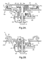
- FIGS. 2A-2D are taken through the bolt 70 and alignment post 35, and illustrate an installation of the exterior and interior components 14 and 16 of antenna module 10 on panel 12 and the functionality of the aforementioned constituent elements.
- FIG. 2A also depicts the interior component 16 being positioned from inside the vehicle cabin for attachment to the installed exterior component 14. In the illustrated position of interior component 16, the finger hooks 80 of connector assembly housing 64 have not yet protruded through the openings 40 of boss 34, and the standoff post 42 has not yet entered the opening 74 of housing 64.
- the circuit board 26, connector terminals 28 and gasket 24 have been omitted for convenience, and the interior component 16 is advanced toward the installed exterior component 14 so that the unthreaded stub 70a of bolt 70 is piloted into the opening 34a of boss 34. Also, the standoff post 42 has entered the opening 74 of connector assembly housing 64. The interface between bolt stub 70a and the opening 34a of boss 34 centers the interior component 16 with respect to the exterior component 14, while the interface between standoff post 42 and the opening 74 of housing 64 ensures accurate initial alignment of the connector terminals 28 and 65.
- the finger hooks 80 of connector assembly housing 64 protrude through the boss openings 40 and resiliently engage an internal shoulder 75 of boss 34 to temporarily attach the interior component 16 to the installed exterior component 14.
- the finger hooks 80 temporarily attach both the exterior and interior components 14 and 16 to panel 12, and such components do not need to be manually held in place by the installer.
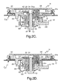
- FIGS. 2C and 2D illustrate the process of permanently attaching the exterior and interior components 14 and 16 to panel 12 by driving the bolt 70 into the threaded opening 34a of boss 34.
- the bolt 70 has been advanced to the point where the legs 72 of clip 68 contact the interior surface of panel 12.
- the electrical terminals 28 and 65 of exterior and interior components 14 and 16 begin to engage, and complementary features on the boss 34 and the connector assembly housing 64 ensure accurate alignment of the connector terminals 28, 65 as they come together.
- the bolt 70 has been driven to the point where the base of clip 68 adjacent the bolt 70 engages the standoff 42 of boss 34, limiting the travel of bolt 70.
- the connector terminals 28, 65 are fully coupled and the gasket 24 is pressed against the exterior surface of the panel 12.
- the legs 72 of clip 68 are allowed to yield or buckle as shown in this final stage of attachment, which compensates for variations in the thickness of panel 12 and cumulative dimensional variations in the antenna assembly due to individual component tolerances.
- the present invention provides an antenna module that is easily and quickly installed by one person if desired, while ensuring secure mechanical attachment and reliable electrical connections. While the present invention has been described with respect to the illustrated embodiment, it is recognized that numerous modifications and variations in addition to those mentioned herein will occur to those skilled in the art.
- the antenna module 10 may be mounted on a panel other than a roof panel
- the standoff post 42 could be mounted on the interior component 16 instead of the exterior component 14, and so on. Accordingly, it is intended that the invention not be limited to the disclosed embodiment, but that it have the full scope permitted by the language of the following claims.
Landscapes
- Engineering & Computer Science (AREA)
- Remote Sensing (AREA)
- Support Of Aerials (AREA)
- Details Of Connecting Devices For Male And Female Coupling (AREA)
- Fittings On The Vehicle Exterior For Carrying Loads, And Devices For Holding Or Mounting Articles (AREA)
- Details Of Aerials (AREA)
Abstract
Description
- The present invention relates to an antenna module for a panel such as the roof of a vehicle, and more particularly to a fastening and electrical connection apparatus for the module.
- Factory installation of a panel-mounted vehicle antenna module is often an awkward and time-consuming process. In a typical installation, electrical jumper wires from the antenna module are fed through an opening in the vehicle roof, whereafter the module is fastened to the roof with screws or a threaded nut, and the jumper wires individually connected to a wiring harness in the cabin of the vehicle. See, for example, the
U.S. Patent No. 6,930,643, issued on August 16, 2005 , and incorporated herein by reference. What is desired is an antenna module that can be easily and quickly installed without compromising the reliability of the mechanical and electrical connections. - The present invention is directed to an improved panel-mounted antenna module for a vehicle including an exterior component and an interior component that are joined in a single operation to simultaneously achieve both mechanical fastening of the module and through-the-panel electrical connections of the antenna. The interior and exterior components are equipped with electrical connectors that are coupled when the interior and exterior components are joined, and alignment features that ensure accurate alignment of the connector terminals. The exterior component includes a gasket that seals against the panel, and a set of metal tangs that temporarily retain the exterior component in position while the interior component is installed from the panel interior. The interior component includes a set of resilient hooks that engage a shoulder of the exterior component to temporarily retain the interior component in place, and a bolt that is tightened to complete the electrical connections and to permanently join the interior and exterior components. Preferably, the interior component also includes a set of electrical jumper cables that are hardwired to the respective electrical connectors to simplify connection of the module to the vehicle wiring harness.
-
- FIG. 1 is an exploded view of a panel-mounted vehicle antenna module according to the present invention;
- FIGS. 2A-2D are cross-sectional views of interior and exterior components of the antenna module of FIG. 1 during its installation on a vehicle panel. FIG. 2A illustrates the exterior component temporarily retained in place on the panel and an initial positioning of the interior component; FIG. 2B illustrates temporary mechanical retention of the interior component; FIG. 2C illustrates partially completed permanent attachment of the interior and exterior components and their electrical connector terminals; and FIG. 2D illustrates the completed permanent attachment of the interior and exterior components.
- Referring to FIG. 1, the
reference numeral 10 generally designates the panel-mounted antenna module of this invention, disassembled in part to more clearly illustrate its constituent elements, and thereference numeral 12 designates an exterior panel of a vehicle, such as a roof panel. In general, theantenna module 10 includes anexterior component 14 that is installed against an exterior or outside surface of thepanel 12, and aninterior component 16 that is installed against an interior or inside surface of the panel 12 (that is, from inside the vehicle cabin if thepanel 12 is a roof panel). - The
exterior component 14 ofantenna module 10 includes anelectrical assembly 18, ametal retainer clip 20, ahousing 22, and a rubber orpolymeric gasket 24. Theelectrical assembly 18 includes a printedcircuit board 26 and a three-terminal FAKRA-standard SMB connector 28 electrically coupled at itsbase 30 to the inboard face ofcircuit board 26. A conventional exterior-mount antenna assembly (not shown) such as depicted in the aforementionedU.S. Patent No. 6,930,643 is fastened tohousing 22 and electrically coupled to the outboard face ofcircuit board 26. Various electronic devices (also not shown) mounted on thecircuit board 26 condition the received radio frequency signals and couple them to theconnector terminals retainer clip 20 includes a set of three prongs ortangs connector terminals panel 12. Thehousing 22 has a central Y-shaped boss 34 with a threadedcentral opening 34a, and analignment post 35. Theboss 34 has a first set ofperipheral openings 36 through which theconnector terminals 28a-28c pass, and a second set ofperipheral openings 38 through which thetangs 32a-32c ofretainer clip 20 protrude. A third set ofopenings 40 in the inboard face ofboss 34 are used for temporary mechanical attachment of the exterior andinterior components standoff post 42 extending out ofboss 34 towardpanel 12 presets the installed spacing between exterior andinterior components housing 22 includes atrough 44 at its periphery for receiving theouter periphery 24a ofgasket 24; theinner periphery 24b of gasket 24 seats against the base ofhousing 22 adjacent ahousing lip 46 surrounding theboss 34 andalignment post 35. - The
panel 12 is provided with amajor opening 50 for receiving thehousing boss 34 andterminals 28a-28c, and aminor opening 52 for receiving thehousing alignment post 35. The orientation of theopenings antenna module 10 relative to thepanel 12. Theinner periphery 24b of gasket 24 seals around thepanel openings outer periphery 24a of gasket 24 seals around thehousing 22 ofexterior component 14. The tangs 32-32c ofretainer clip 20 protrude radially outward from theboss openings 38, and engage the inner periphery of thepanel 12 about themajor opening 50 when theexterior component 14 is pushed into place onpanel 12 by an installer. This temporarily retains theexterior component 14 in place on thepanel 12 while theinterior component 16 is installed. - The
interior component 16 includes aconnector assembly 60 and aclamp assembly 62. Theconnector assembly 60 has ahousing 64 in which are mounted a set of three FAKRA-standardSMB connector terminals 65 designed to mate with theconnector terminals 28a-28c ofexterior component 14. A set ofcables 66 applied to theconnector terminals 65 pass through a sidewall ofhousing 64, and terminate in connectors (not shown) for attachment to a wiring harness in the vehicle cabin. Thehousing 64 also includes anopening 67 for receiving thestandoff post 42 ofexterior component 14, and a set of three integrally fashioned finger hooks (hidden in FIG. 1) that are received in theboss openings 40 ofexterior component 14 to effect temporary mechanical attachment of the interior andexterior components panel 12. Theclamp assembly 62 includes a three-leggedmetal clip 68 and acaptive bolt 70 that is received in the threadedopening 34a ofboss 34 for permanent attachment of the exterior andinterior components legs 72 ofclip 68 pass through suitable openings in theconnector assembly housing 64, and thebolt 70 passes through acentral opening 74. Theclip 68 is retained in thehousing 64 bytangs 76 formed on the ends of thelegs 72. - The sectional views of FIGS. 2A-2D are taken through the
bolt 70 andalignment post 35, and illustrate an installation of the exterior andinterior components antenna module 10 onpanel 12 and the functionality of the aforementioned constituent elements. FIGS. 2A-2D depict one of the previously mentioned but un-shownfinger hooks 80 ofinterior component housing 64. - In the view of FIG. 2A, the
exterior component 14 is placed in position on the exterior surface ofpanel 12, with theboss 34,connector terminals 28 andretainer tangs 32a passing through themajor opening 50 ofpanel 12 , and thealignment post 35 passing through theminor opening 52. Significantly, thetangs 32a-32c ofretainer clip 20 seat against theinside surface 12a ofpanel 12 to temporarily retain theexterior component 14 in place while theinterior component 16 is being installed. FIG. 2A also depicts theinterior component 16 being positioned from inside the vehicle cabin for attachment to the installedexterior component 14. In the illustrated position ofinterior component 16, thefinger hooks 80 ofconnector assembly housing 64 have not yet protruded through theopenings 40 ofboss 34, and thestandoff post 42 has not yet entered the opening 74 ofhousing 64. - In the view of FIG. 2B, the
circuit board 26,connector terminals 28 andgasket 24 have been omitted for convenience, and theinterior component 16 is advanced toward the installedexterior component 14 so that theunthreaded stub 70a ofbolt 70 is piloted into the opening 34a ofboss 34. Also, thestandoff post 42 has entered the opening 74 ofconnector assembly housing 64. The interface betweenbolt stub 70a and the opening 34a ofboss 34 centers theinterior component 16 with respect to theexterior component 14, while the interface betweenstandoff post 42 and theopening 74 ofhousing 64 ensures accurate initial alignment of theconnector terminals finger hooks 80 ofconnector assembly housing 64 protrude through theboss openings 40 and resiliently engage an internal shoulder 75 ofboss 34 to temporarily attach theinterior component 16 to the installedexterior component 14. At this stage, thefinger hooks 80 temporarily attach both the exterior andinterior components panel 12, and such components do not need to be manually held in place by the installer. - FIGS. 2C and 2D illustrate the process of permanently attaching the exterior and
interior components panel 12 by driving thebolt 70 into the threadedopening 34a ofboss 34. In the view of FIG. 2C, thebolt 70 has been advanced to the point where thelegs 72 ofclip 68 contact the interior surface ofpanel 12. Also, theelectrical terminals interior components boss 34 and theconnector assembly housing 64 ensure accurate alignment of theconnector terminals bolt 70 has been driven to the point where the base ofclip 68 adjacent thebolt 70 engages thestandoff 42 ofboss 34, limiting the travel ofbolt 70. At this point, theconnector terminals gasket 24 is pressed against the exterior surface of thepanel 12. Thelegs 72 ofclip 68 are allowed to yield or buckle as shown in this final stage of attachment, which compensates for variations in the thickness ofpanel 12 and cumulative dimensional variations in the antenna assembly due to individual component tolerances. Once theantenna module 10 has been so installed, thecables 66 are connected to the vehicle wiring harness, completing the installation. - In summary, the present invention provides an antenna module that is easily and quickly installed by one person if desired, while ensuring secure mechanical attachment and reliable electrical connections. While the present invention has been described with respect to the illustrated embodiment, it is recognized that numerous modifications and variations in addition to those mentioned herein will occur to those skilled in the art. For example, the
antenna module 10 may be mounted on a panel other than a roof panel, thestandoff post 42 could be mounted on theinterior component 16 instead of theexterior component 14, and so on. Accordingly, it is intended that the invention not be limited to the disclosed embodiment, but that it have the full scope permitted by the language of the following claims.
Claims (11)
- An antenna module (10) for installation on a vehicle panel (12), the antenna module comprising:an exterior component (14) adapted to be placed against an exterior surface of said panel (12), said exterior component including an antenna circuit (26) and a first set of connector terminals (28) electrically coupled to said antenna circuit (26); andan interior component (16) adapted to be placed against an interior surface (12a) of said panel (12) and joined to said exterior component (14), said interior component (16) including a second set of connector terminals (65); where said first set of connector terminals (28) is joined with said second set of connector terminals (65) by the joining of said interior component (16) to said exterior component (14) to electrically couple said antenna circuit (26) to said second set of connector terminals (65).
- The antenna module of claim 1, wherein:said interior component (16) includes a set of jumper cables (66) coupled to said second set of connector terminals (65) for attachment of said antenna module (10) to a wiring harness of said vehicle.
- The antenna module of claim 1, wherein:said exterior component (14) includes a resilient retainer clip (20) having tangs (32a-32c) that seat against the interior surface (12a) of said panel (12) for temporarily maintaining the placement of said exterior component (14) against said panel (12).
- The antenna module of claim 1, wherein:said interior component (16) includes resilient hooks (80) that seat against said exterior component (14) to retain the placement of said interior component (16) against said panel (12).
- The antenna module of claim 4, wherein:said exterior component (14) includes openings (40) in which the resilient hooks (80) of said interior component (16) are received for aligning said second set of connector terminals (65) with said first set of connector terminals (28).
- The antenna module of claim 1, further comprising:a first retainer mechanism (20) for temporarily maintaining the placement of said exterior component (14) against said panel (12);a second retainer mechanism (80) for temporarily maintaining the placement of said interior component (16) against said panel (12); anda bolt (70) for joining said interior component (16) to said exterior component (14).
- The antenna module of claim 6, wherein:said bolt (70) is captured in said interior component (16) and threaded into said exterior component (14), said bolt (70) having an unthreaded stub (70a) that is initially piloted into said exterior component (14) to center said interior component (16) with respect to said exterior component (14).
- The antenna module of claim 1, wherein:said interior component (16) includes a bolt (70) that is threaded into said exterior component (14) for joining said interior component (16) to said exterior component (14), and a clamping element (68) that is driven into contact with the interior surface (12a) of said panel (12) as said bolt (70) is threaded into said exterior component (14).
- The antenna module of claim 8, wherein:said exterior component (14) includes a standoff post (42) that is contacted by said clamping element (68) to limit a travel of said bolt (70).
- The antenna module of claim 9, wherein:said interior component (16) includes an opening (67) in which the standoff post (42) of said exterior component (14) is received for aligning said second set of connector terminals (65) with said first set of connector terminals (28).
- The antenna module of claim 9, wherein:a portion (72) of said clamping element (68) that contacts the interior surface (12a) of said panel (12) is yieldable and buckles before said clamping element (68) contacts said standoff post (42).
Applications Claiming Priority (1)
| Application Number | Priority Date | Filing Date | Title |
|---|---|---|---|
| US11/437,363 US7710333B2 (en) | 2006-05-19 | 2006-05-19 | Fastening and connection apparatus for a panel-mounted vehicle antenna module |
Publications (2)
| Publication Number | Publication Date |
|---|---|
| EP1858110A1 true EP1858110A1 (en) | 2007-11-21 |
| EP1858110B1 EP1858110B1 (en) | 2009-08-05 |
Family
ID=38326397
Family Applications (1)
| Application Number | Title | Priority Date | Filing Date |
|---|---|---|---|
| EP07075364A Not-in-force EP1858110B1 (en) | 2006-05-19 | 2007-05-08 | Fastening and connection apparatus for a panel-mounted vehicle antenna module |
Country Status (4)
| Country | Link |
|---|---|
| US (1) | US7710333B2 (en) |
| EP (1) | EP1858110B1 (en) |
| AT (1) | ATE438938T1 (en) |
| DE (1) | DE602007001831D1 (en) |
Cited By (4)
| Publication number | Priority date | Publication date | Assignee | Title |
|---|---|---|---|---|
| WO2017178387A1 (en) * | 2016-04-12 | 2017-10-19 | Valeo Comfort And Driving Assistance | Antenna module for a motor vehicle |
| WO2017178385A1 (en) * | 2016-04-12 | 2017-10-19 | Valeo Comfort And Driving Assistance | Electronic module for a motor vehicle |
| FR3060213A1 (en) * | 2016-12-08 | 2018-06-15 | Valeo Comfort And Driving Assistance | ANTENNA MODULE (S) FOR A MOTOR VEHICLE |
| FR3060212A1 (en) * | 2016-12-08 | 2018-06-15 | Valeo Comfort And Driving Assistance | ELECTRONIC MODULE FOR MOTOR VEHICLE |
Families Citing this family (25)
| Publication number | Priority date | Publication date | Assignee | Title |
|---|---|---|---|---|
| DE102005033592A1 (en) * | 2005-07-19 | 2007-01-25 | Hirschmann Car Communication Gmbh | Carrier for receiving an antenna amplifier of a vehicle |
| JP4871949B2 (en) | 2007-12-20 | 2012-02-08 | 原田工業株式会社 | Patch antenna device |
| US8059044B2 (en) * | 2008-05-15 | 2011-11-15 | Laird Technologies Gmbh | Antenna mounting apparatus and methods including claw fasteners and/or bayonet locking structures |
| JP4524318B2 (en) * | 2008-05-27 | 2010-08-18 | 原田工業株式会社 | Automotive noise filter |
| JP5114325B2 (en) * | 2008-07-08 | 2013-01-09 | 原田工業株式会社 | Roof mount antenna device for vehicle |
| DE102008041125A1 (en) * | 2008-08-08 | 2010-02-11 | Robert Bosch Gmbh | Holder for a motor vehicle attachment and device for holding a motor vehicle attachment |
| JP4525823B2 (en) * | 2008-12-04 | 2010-08-18 | ミツミ電機株式会社 | Electrical equipment cabinet and antenna device |
| JP5241549B2 (en) * | 2009-02-09 | 2013-07-17 | 富士通テン株式会社 | Connector for vehicle antenna |
| JP4832549B2 (en) * | 2009-04-30 | 2011-12-07 | 原田工業株式会社 | Vehicle antenna apparatus using space filling curve |
| DE102010019383B4 (en) | 2009-05-04 | 2024-03-14 | Hirschmann Car Communication Gmbh | Attaching an electronic device such as an impedance converter or amplifier to a vehicle body |
| JP4955094B2 (en) * | 2009-11-02 | 2012-06-20 | 原田工業株式会社 | Patch antenna |
| JP5585139B2 (en) * | 2010-03-18 | 2014-09-10 | ミツミ電機株式会社 | Antenna device |
| EP2367232A2 (en) * | 2010-03-18 | 2011-09-21 | Mitsumi Electric Co., Ltd. | Fixation structure of a vehicular antenna apparatus |
| US8441401B2 (en) | 2010-04-29 | 2013-05-14 | Laird Technologies, Inc. | Vehicle antenna mounting apparatus, systems, and methods |
| US8537061B2 (en) * | 2010-05-17 | 2013-09-17 | General Electric Company | System and apparatus for locomotive radio communications |
| US8816917B2 (en) | 2011-01-12 | 2014-08-26 | Harada Industry Co., Ltd. | Antenna device |
| JP5274597B2 (en) | 2011-02-15 | 2013-08-28 | 原田工業株式会社 | Vehicle pole antenna |
| JP5654917B2 (en) | 2011-03-24 | 2015-01-14 | 原田工業株式会社 | Antenna device |
| JP5627641B2 (en) * | 2012-06-07 | 2014-11-19 | 原田工業株式会社 | Roof mount antenna device for vehicle |
| USD726696S1 (en) | 2012-09-12 | 2015-04-14 | Harada Industry Co., Ltd. | Vehicle antenna |
| US9413062B2 (en) * | 2013-12-07 | 2016-08-09 | Ethertronics, Inc. | Mounting flange for installation of distributed antenna systems |
| TWM481493U (en) * | 2014-01-03 | 2014-07-01 | Grand Tek Technology Co Ltd | Antenna connecting structure |
| US10374653B2 (en) | 2015-08-13 | 2019-08-06 | Laird Technologies, Inc. | V2X antenna systems |
| DE102019211755B3 (en) * | 2019-08-06 | 2020-12-31 | Volkswagen Aktiengesellschaft | Mounting system for a modular antenna |
| EP4396466B1 (en) * | 2021-08-31 | 2026-03-04 | AUMOVIO Germany GmbH | Fastening arrangement for fastening a device housing of a device to a vehicle panel of a motor vehicle, and motor vehicle and device |
Citations (6)
| Publication number | Priority date | Publication date | Assignee | Title |
|---|---|---|---|---|
| FR2691841A1 (en) * | 1992-05-29 | 1993-12-03 | Peugeot | Radio aerial for car - has lower element connected to coaxial cable and click fitting internally into hole in car bodywork, with antenna support plugging into it from exterior of vehicle |
| EP0632520A1 (en) * | 1993-06-30 | 1995-01-04 | Mecaniplast | Antenna base suitable for receiving a L-shaped bent connector |
| FR2773913A1 (en) * | 1998-01-22 | 1999-07-23 | Bosch Gmbh Robert | Connector for linking cables to external vehicle radio aerial |
| US6930643B2 (en) | 2003-11-03 | 2005-08-16 | Delphi Technologies, Inc. | Antenna module assembly |
| EP1648049A1 (en) | 2004-10-12 | 2006-04-19 | Harada Industry Co., Ltd. | Antenna mounting device |
| EP1653555A2 (en) * | 2004-10-30 | 2006-05-03 | Hirschmann Car Communication GmbH | apparatus for coupling a wiring harness to an antenna |
-
2006
- 2006-05-19 US US11/437,363 patent/US7710333B2/en not_active Expired - Fee Related
-
2007
- 2007-05-08 DE DE602007001831T patent/DE602007001831D1/en active Active
- 2007-05-08 EP EP07075364A patent/EP1858110B1/en not_active Not-in-force
- 2007-05-08 AT AT07075364T patent/ATE438938T1/en not_active IP Right Cessation
Patent Citations (6)
| Publication number | Priority date | Publication date | Assignee | Title |
|---|---|---|---|---|
| FR2691841A1 (en) * | 1992-05-29 | 1993-12-03 | Peugeot | Radio aerial for car - has lower element connected to coaxial cable and click fitting internally into hole in car bodywork, with antenna support plugging into it from exterior of vehicle |
| EP0632520A1 (en) * | 1993-06-30 | 1995-01-04 | Mecaniplast | Antenna base suitable for receiving a L-shaped bent connector |
| FR2773913A1 (en) * | 1998-01-22 | 1999-07-23 | Bosch Gmbh Robert | Connector for linking cables to external vehicle radio aerial |
| US6930643B2 (en) | 2003-11-03 | 2005-08-16 | Delphi Technologies, Inc. | Antenna module assembly |
| EP1648049A1 (en) | 2004-10-12 | 2006-04-19 | Harada Industry Co., Ltd. | Antenna mounting device |
| EP1653555A2 (en) * | 2004-10-30 | 2006-05-03 | Hirschmann Car Communication GmbH | apparatus for coupling a wiring harness to an antenna |
Cited By (4)
| Publication number | Priority date | Publication date | Assignee | Title |
|---|---|---|---|---|
| WO2017178387A1 (en) * | 2016-04-12 | 2017-10-19 | Valeo Comfort And Driving Assistance | Antenna module for a motor vehicle |
| WO2017178385A1 (en) * | 2016-04-12 | 2017-10-19 | Valeo Comfort And Driving Assistance | Electronic module for a motor vehicle |
| FR3060213A1 (en) * | 2016-12-08 | 2018-06-15 | Valeo Comfort And Driving Assistance | ANTENNA MODULE (S) FOR A MOTOR VEHICLE |
| FR3060212A1 (en) * | 2016-12-08 | 2018-06-15 | Valeo Comfort And Driving Assistance | ELECTRONIC MODULE FOR MOTOR VEHICLE |
Also Published As
| Publication number | Publication date |
|---|---|
| ATE438938T1 (en) | 2009-08-15 |
| US7710333B2 (en) | 2010-05-04 |
| EP1858110B1 (en) | 2009-08-05 |
| US20070279302A1 (en) | 2007-12-06 |
| DE602007001831D1 (en) | 2009-09-17 |
Similar Documents
| Publication | Publication Date | Title |
|---|---|---|
| EP1858110B1 (en) | Fastening and connection apparatus for a panel-mounted vehicle antenna module | |
| US7002523B2 (en) | Antenna device | |
| US6450833B1 (en) | Seven-way trailer connector | |
| EP2064775A2 (en) | Antenna assemblies including standard electrical connections and captured retainers and fasteners | |
| US20110267243A1 (en) | Vehicle antenna mounting apparatus, systems, and methods | |
| US8059044B2 (en) | Antenna mounting apparatus and methods including claw fasteners and/or bayonet locking structures | |
| CN102870289B (en) | Attachable plug connectors | |
| US20090303142A1 (en) | Mounting System and Mounting Procedure for a Vehicle Antenna | |
| US7736202B1 (en) | Contact assembly for attachment to an electronics module | |
| US20060094294A1 (en) | Connector for joining cable conductors with an antenna | |
| CN101114749B (en) | Connecting device with locking mechanism | |
| US6943292B2 (en) | Printed circuit board stiffener | |
| US7387518B2 (en) | Grounding attachment assembly | |
| JP2019110026A (en) | Mounting structure for connector | |
| US10476145B2 (en) | Radio frequency sensor module with mounting ears | |
| US4827273A (en) | Antenna mounting apparatus | |
| US12095137B2 (en) | Fastening system for a modular antenna | |
| KR20100006380U (en) | Antenna mounting unit | |
| JP3026639U (en) | Electrical component mounting system for airbag modules utilizing studs | |
| US20060057862A1 (en) | Connecting device | |
| EP1858111A1 (en) | Automotive component and method for mounting of an automotive component | |
| US20100149070A1 (en) | Electrical connection structure and antenna apparatus | |
| JP2503690Y2 (en) | Electronic device case body | |
| EP1356997B1 (en) | Vehicle component having an electrical conductor adhesively secured into the component | |
| US20040211582A1 (en) | Vehicle component having an electrical conductor adhesively secured into the component |
Legal Events
| Date | Code | Title | Description |
|---|---|---|---|
| PUAI | Public reference made under article 153(3) epc to a published international application that has entered the european phase |
Free format text: ORIGINAL CODE: 0009012 |
|
| AK | Designated contracting states |
Kind code of ref document: A1 Designated state(s): AT BE BG CH CY CZ DE DK EE ES FI FR GB GR HU IE IS IT LI LT LU LV MC MT NL PL PT RO SE SI SK TR |
|
| AX | Request for extension of the european patent |
Extension state: AL BA HR MK YU |
|
| 17P | Request for examination filed |
Effective date: 20080521 |
|
| 17Q | First examination report despatched |
Effective date: 20080626 |
|
| AKX | Designation fees paid |
Designated state(s): AT BE BG CH CY CZ DE DK EE ES FI FR GB GR HU IE IS IT LI LT LU LV MC MT NL PL PT RO SE SI SK TR |
|
| GRAP | Despatch of communication of intention to grant a patent |
Free format text: ORIGINAL CODE: EPIDOSNIGR1 |
|
| GRAS | Grant fee paid |
Free format text: ORIGINAL CODE: EPIDOSNIGR3 |
|
| GRAA | (expected) grant |
Free format text: ORIGINAL CODE: 0009210 |
|
| AK | Designated contracting states |
Kind code of ref document: B1 Designated state(s): AT BE BG CH CY CZ DE DK EE ES FI FR GB GR HU IE IS IT LI LT LU LV MC MT NL PL PT RO SE SI SK TR |
|
| REG | Reference to a national code |
Ref country code: GB Ref legal event code: FG4D |
|
| REG | Reference to a national code |
Ref country code: CH Ref legal event code: EP |
|
| REG | Reference to a national code |
Ref country code: IE Ref legal event code: FG4D |
|
| REF | Corresponds to: |
Ref document number: 602007001831 Country of ref document: DE Date of ref document: 20090917 Kind code of ref document: P |
|
| LTIE | Lt: invalidation of european patent or patent extension |
Effective date: 20090805 |
|
| PG25 | Lapsed in a contracting state [announced via postgrant information from national office to epo] |
Ref country code: AT Free format text: LAPSE BECAUSE OF FAILURE TO SUBMIT A TRANSLATION OF THE DESCRIPTION OR TO PAY THE FEE WITHIN THE PRESCRIBED TIME-LIMIT Effective date: 20090805 Ref country code: ES Free format text: LAPSE BECAUSE OF FAILURE TO SUBMIT A TRANSLATION OF THE DESCRIPTION OR TO PAY THE FEE WITHIN THE PRESCRIBED TIME-LIMIT Effective date: 20091116 Ref country code: IS Free format text: LAPSE BECAUSE OF FAILURE TO SUBMIT A TRANSLATION OF THE DESCRIPTION OR TO PAY THE FEE WITHIN THE PRESCRIBED TIME-LIMIT Effective date: 20091205 Ref country code: FI Free format text: LAPSE BECAUSE OF FAILURE TO SUBMIT A TRANSLATION OF THE DESCRIPTION OR TO PAY THE FEE WITHIN THE PRESCRIBED TIME-LIMIT Effective date: 20090805 Ref country code: LT Free format text: LAPSE BECAUSE OF FAILURE TO SUBMIT A TRANSLATION OF THE DESCRIPTION OR TO PAY THE FEE WITHIN THE PRESCRIBED TIME-LIMIT Effective date: 20090805 Ref country code: SE Free format text: LAPSE BECAUSE OF FAILURE TO SUBMIT A TRANSLATION OF THE DESCRIPTION OR TO PAY THE FEE WITHIN THE PRESCRIBED TIME-LIMIT Effective date: 20090805 |
|
| NLV1 | Nl: lapsed or annulled due to failure to fulfill the requirements of art. 29p and 29m of the patents act | ||
| PG25 | Lapsed in a contracting state [announced via postgrant information from national office to epo] |
Ref country code: PL Free format text: LAPSE BECAUSE OF FAILURE TO SUBMIT A TRANSLATION OF THE DESCRIPTION OR TO PAY THE FEE WITHIN THE PRESCRIBED TIME-LIMIT Effective date: 20090805 Ref country code: SI Free format text: LAPSE BECAUSE OF FAILURE TO SUBMIT A TRANSLATION OF THE DESCRIPTION OR TO PAY THE FEE WITHIN THE PRESCRIBED TIME-LIMIT Effective date: 20090805 Ref country code: NL Free format text: LAPSE BECAUSE OF FAILURE TO SUBMIT A TRANSLATION OF THE DESCRIPTION OR TO PAY THE FEE WITHIN THE PRESCRIBED TIME-LIMIT Effective date: 20090805 Ref country code: LV Free format text: LAPSE BECAUSE OF FAILURE TO SUBMIT A TRANSLATION OF THE DESCRIPTION OR TO PAY THE FEE WITHIN THE PRESCRIBED TIME-LIMIT Effective date: 20090805 |
|
| PG25 | Lapsed in a contracting state [announced via postgrant information from national office to epo] |
Ref country code: BG Free format text: LAPSE BECAUSE OF FAILURE TO SUBMIT A TRANSLATION OF THE DESCRIPTION OR TO PAY THE FEE WITHIN THE PRESCRIBED TIME-LIMIT Effective date: 20091105 Ref country code: PT Free format text: LAPSE BECAUSE OF FAILURE TO SUBMIT A TRANSLATION OF THE DESCRIPTION OR TO PAY THE FEE WITHIN THE PRESCRIBED TIME-LIMIT Effective date: 20091205 |
|
| PG25 | Lapsed in a contracting state [announced via postgrant information from national office to epo] |
Ref country code: EE Free format text: LAPSE BECAUSE OF FAILURE TO SUBMIT A TRANSLATION OF THE DESCRIPTION OR TO PAY THE FEE WITHIN THE PRESCRIBED TIME-LIMIT Effective date: 20090805 Ref country code: RO Free format text: LAPSE BECAUSE OF FAILURE TO SUBMIT A TRANSLATION OF THE DESCRIPTION OR TO PAY THE FEE WITHIN THE PRESCRIBED TIME-LIMIT Effective date: 20090805 Ref country code: DK Free format text: LAPSE BECAUSE OF FAILURE TO SUBMIT A TRANSLATION OF THE DESCRIPTION OR TO PAY THE FEE WITHIN THE PRESCRIBED TIME-LIMIT Effective date: 20090805 Ref country code: CZ Free format text: LAPSE BECAUSE OF FAILURE TO SUBMIT A TRANSLATION OF THE DESCRIPTION OR TO PAY THE FEE WITHIN THE PRESCRIBED TIME-LIMIT Effective date: 20090805 |
|
| PG25 | Lapsed in a contracting state [announced via postgrant information from national office to epo] |
Ref country code: SK Free format text: LAPSE BECAUSE OF FAILURE TO SUBMIT A TRANSLATION OF THE DESCRIPTION OR TO PAY THE FEE WITHIN THE PRESCRIBED TIME-LIMIT Effective date: 20090805 |
|
| PLBE | No opposition filed within time limit |
Free format text: ORIGINAL CODE: 0009261 |
|
| STAA | Information on the status of an ep patent application or granted ep patent |
Free format text: STATUS: NO OPPOSITION FILED WITHIN TIME LIMIT |
|
| PG25 | Lapsed in a contracting state [announced via postgrant information from national office to epo] |
Ref country code: BE Free format text: LAPSE BECAUSE OF FAILURE TO SUBMIT A TRANSLATION OF THE DESCRIPTION OR TO PAY THE FEE WITHIN THE PRESCRIBED TIME-LIMIT Effective date: 20090805 |
|
| 26N | No opposition filed |
Effective date: 20100507 |
|
| PG25 | Lapsed in a contracting state [announced via postgrant information from national office to epo] |
Ref country code: GR Free format text: LAPSE BECAUSE OF FAILURE TO SUBMIT A TRANSLATION OF THE DESCRIPTION OR TO PAY THE FEE WITHIN THE PRESCRIBED TIME-LIMIT Effective date: 20091106 |
|
| PG25 | Lapsed in a contracting state [announced via postgrant information from national office to epo] |
Ref country code: MC Free format text: LAPSE BECAUSE OF NON-PAYMENT OF DUE FEES Effective date: 20100531 |
|
| PG25 | Lapsed in a contracting state [announced via postgrant information from national office to epo] |
Ref country code: IT Free format text: LAPSE BECAUSE OF FAILURE TO SUBMIT A TRANSLATION OF THE DESCRIPTION OR TO PAY THE FEE WITHIN THE PRESCRIBED TIME-LIMIT Effective date: 20090805 |
|
| PG25 | Lapsed in a contracting state [announced via postgrant information from national office to epo] |
Ref country code: MT Free format text: LAPSE BECAUSE OF FAILURE TO SUBMIT A TRANSLATION OF THE DESCRIPTION OR TO PAY THE FEE WITHIN THE PRESCRIBED TIME-LIMIT Effective date: 20090805 Ref country code: IE Free format text: LAPSE BECAUSE OF NON-PAYMENT OF DUE FEES Effective date: 20100508 |
|
| REG | Reference to a national code |
Ref country code: CH Ref legal event code: PL |
|
| PG25 | Lapsed in a contracting state [announced via postgrant information from national office to epo] |
Ref country code: CH Free format text: LAPSE BECAUSE OF NON-PAYMENT OF DUE FEES Effective date: 20110531 Ref country code: LI Free format text: LAPSE BECAUSE OF NON-PAYMENT OF DUE FEES Effective date: 20110531 |
|
| PG25 | Lapsed in a contracting state [announced via postgrant information from national office to epo] |
Ref country code: CY Free format text: LAPSE BECAUSE OF FAILURE TO SUBMIT A TRANSLATION OF THE DESCRIPTION OR TO PAY THE FEE WITHIN THE PRESCRIBED TIME-LIMIT Effective date: 20090805 |
|
| PG25 | Lapsed in a contracting state [announced via postgrant information from national office to epo] |
Ref country code: HU Free format text: LAPSE BECAUSE OF FAILURE TO SUBMIT A TRANSLATION OF THE DESCRIPTION OR TO PAY THE FEE WITHIN THE PRESCRIBED TIME-LIMIT Effective date: 20100206 Ref country code: LU Free format text: LAPSE BECAUSE OF NON-PAYMENT OF DUE FEES Effective date: 20100508 |
|
| PG25 | Lapsed in a contracting state [announced via postgrant information from national office to epo] |
Ref country code: TR Free format text: LAPSE BECAUSE OF FAILURE TO SUBMIT A TRANSLATION OF THE DESCRIPTION OR TO PAY THE FEE WITHIN THE PRESCRIBED TIME-LIMIT Effective date: 20090805 |
|
| REG | Reference to a national code |
Ref country code: FR Ref legal event code: PLFP Year of fee payment: 10 |
|
| REG | Reference to a national code |
Ref country code: FR Ref legal event code: PLFP Year of fee payment: 11 |
|
| REG | Reference to a national code |
Ref country code: FR Ref legal event code: PLFP Year of fee payment: 12 |
|
| REG | Reference to a national code |
Ref country code: DE Ref legal event code: R082 Ref document number: 602007001831 Country of ref document: DE Representative=s name: MANITZ FINSTERWALD PATENT- UND RECHTSANWALTSPA, DE Ref country code: DE Ref legal event code: R082 Ref document number: 602007001831 Country of ref document: DE Representative=s name: MANITZ FINSTERWALD PATENTANWAELTE PARTMBB, DE Ref country code: DE Ref legal event code: R081 Ref document number: 602007001831 Country of ref document: DE Owner name: APTIV TECHNOLOGIES LIMITED, BB Free format text: FORMER OWNER: DELPHI TECHNOLOGIES, INC., TROY, MICH., US |
|
| REG | Reference to a national code |
Ref country code: GB Ref legal event code: 732E Free format text: REGISTERED BETWEEN 20190117 AND 20190123 |
|
| REG | Reference to a national code |
Ref country code: GB Ref legal event code: 732E Free format text: REGISTERED BETWEEN 20190124 AND 20190130 |
|
| PGFP | Annual fee paid to national office [announced via postgrant information from national office to epo] |
Ref country code: FR Payment date: 20190527 Year of fee payment: 13 |
|
| PGFP | Annual fee paid to national office [announced via postgrant information from national office to epo] |
Ref country code: GB Payment date: 20190528 Year of fee payment: 13 |
|
| GBPC | Gb: european patent ceased through non-payment of renewal fee |
Effective date: 20200508 |
|
| PG25 | Lapsed in a contracting state [announced via postgrant information from national office to epo] |
Ref country code: GB Free format text: LAPSE BECAUSE OF NON-PAYMENT OF DUE FEES Effective date: 20200508 Ref country code: FR Free format text: LAPSE BECAUSE OF NON-PAYMENT OF DUE FEES Effective date: 20200531 |
|
| P01 | Opt-out of the competence of the unified patent court (upc) registered |
Effective date: 20230425 |
|
| PGFP | Annual fee paid to national office [announced via postgrant information from national office to epo] |
Ref country code: DE Payment date: 20240516 Year of fee payment: 18 |
|
| REG | Reference to a national code |
Ref country code: DE Ref legal event code: R081 Ref document number: 602007001831 Country of ref document: DE Owner name: APTIV TECHNOLOGIES AG, CH Free format text: FORMER OWNER: APTIV TECHNOLOGIES LIMITED, ST. MICHAEL, BB |
|
| REG | Reference to a national code |
Ref country code: DE Ref legal event code: R119 Ref document number: 602007001831 Country of ref document: DE |
|
| PG25 | Lapsed in a contracting state [announced via postgrant information from national office to epo] |
Ref country code: DE Free format text: LAPSE BECAUSE OF NON-PAYMENT OF DUE FEES Effective date: 20251202 |