EP1858027A1 - A sensing circuit for semiconductor memories - Google Patents
A sensing circuit for semiconductor memories Download PDFInfo
- Publication number
- EP1858027A1 EP1858027A1 EP06114228A EP06114228A EP1858027A1 EP 1858027 A1 EP1858027 A1 EP 1858027A1 EP 06114228 A EP06114228 A EP 06114228A EP 06114228 A EP06114228 A EP 06114228A EP 1858027 A1 EP1858027 A1 EP 1858027A1
- Authority
- EP
- European Patent Office
- Prior art keywords
- current
- circuit node
- voltage
- node
- yms
- Prior art date
- Legal status (The legal status is an assumption and is not a legal conclusion. Google has not performed a legal analysis and makes no representation as to the accuracy of the status listed.)
- Withdrawn
Links
Images


Classifications
-
- G—PHYSICS
- G11—INFORMATION STORAGE
- G11C—STATIC STORES
- G11C16/00—Erasable programmable read-only memories
- G11C16/02—Erasable programmable read-only memories electrically programmable
- G11C16/06—Auxiliary circuits, e.g. for writing into memory
- G11C16/26—Sensing or reading circuits; Data output circuits
- G11C16/28—Sensing or reading circuits; Data output circuits using differential sensing or reference cells, e.g. dummy cells
-
- G—PHYSICS
- G11—INFORMATION STORAGE
- G11C—STATIC STORES
- G11C16/00—Erasable programmable read-only memories
- G11C16/02—Erasable programmable read-only memories electrically programmable
- G11C16/06—Auxiliary circuits, e.g. for writing into memory
- G11C16/24—Bit-line control circuits
-
- G—PHYSICS
- G11—INFORMATION STORAGE
- G11C—STATIC STORES
- G11C2207/00—Indexing scheme relating to arrangements for writing information into, or reading information out from, a digital store
- G11C2207/06—Sense amplifier related aspects
- G11C2207/063—Current sense amplifiers
-
- G—PHYSICS
- G11—INFORMATION STORAGE
- G11C—STATIC STORES
- G11C7/00—Arrangements for writing information into, or reading information out from, a digital store
- G11C7/06—Sense amplifiers; Associated circuits, e.g. timing or triggering circuits
- G11C7/067—Single-ended amplifiers
-
- G—PHYSICS
- G11—INFORMATION STORAGE
- G11C—STATIC STORES
- G11C7/00—Arrangements for writing information into, or reading information out from, a digital store
- G11C7/12—Bit line control circuits, e.g. drivers, boosters, pull-up circuits, pull-down circuits, precharging circuits, equalising circuits, for bit lines
Definitions
- the present invention generally relates to semiconductor memories, either stand-alone or embedded in more complex integrated circuit electronic systems.
- the invention relates to an improved sensing circuit for a semiconductor memory.
- Non-volatile memories are commonly used in several applications for storing information, both temporarily (in the so-called volatile memories), and permanently (in the so-called non-volatile memories). Non-volatile memories are capable of retaining the stored information even in absence of a power supply source.
- a non-volatile semiconductor memory comprises a matrix of memory cells, e.g., floating gate MOS transistors; each memory cell has a threshold voltage adapted to be programmed to different levels, corresponding to different logic values.
- flash memory is a very popular type of non-volatile memory, which also exhibits the capability of electrically writing and erasing the memory cells.
- each memory cell of a two-level flash memory is adapted to store a single information bit.
- the generic memory cell In an erased condition, the generic memory cell has a relatively low threshold voltage (associated by convention with the logic value "1"); the memory cell is programmed by injecting electrons into its floating gate: in this condition the memory cell has a higher threshold voltage (associated by convention with the logic value "0").
- Multilevel flash memories comprise instead memory cells capable of storing more than just one information bit.
- Each memory cell can be programmed to one of a plurality of different states, each corresponding to a respective range of threshold voltage values.
- each memory cell of a four-level flash memory stores a logic value consisting of two information bits ("11", “10”, “01” e “00", with the logic value "11” that is associated with the lowest threshold voltage range and the logic value "00" that is associated with the highest threshold voltage range).
- semiconductor memories comprise reading circuits, adapted to read the data stored in the memory cells.
- the data stored in the selected memory cell is read by comparing the behavior of the current flowing through the selected memory cell with the behavior of the current(s) provided by one or more reference cells which are programmed to predetermined states.
- the reading circuit has to properly bias the selected memory cell and the reference cells.
- the comparison between the currents flowing through the selected memory cell and the reference memory cells, respectively, is typically performed by sensing circuits, included in the reading circuit and adapted to generate output signals whose value provide an indication of the logic value stored in the selected memory cell.
- a known technique for reading the information stored in the memory cells is the so-called ramp-voltage sensing technique.
- the ramp-voltage sensing technique comprises two different phases: a precharge phase and an evaluation phase.
- the precharge phase Before the evaluation phase of the datum stored in the selected memory cell, the precharge phase is required for precharging an access line (e.g., a bit line) coupled to the selected memory cell, to a predetermined potential, in such a way as to charge stray capacitances intrinsically associated therewith.
- an access line e.g., a bit line
- a current flowing through the bit line causes the charging of the associated stray capacitances, and, accordingly, a corresponding transient is required before the bit line voltage and current reach a steady value.
- the length of this transient depends on a number of factors, such as the operating temperature, the value of a supply voltage of the memory device, and statistical variations of parameters whose values are affected by the manufacturing process.
- the evaluation phase provides for applying a voltage ramp to the control gate of a selected memory cell to be read and to the reference memory cells (having known threshold voltages); the datum stored in the selected memory cell is determined on the basis of a time relationship between the instants at which the selected memory cell and the reference memory cells pass from a first conduction state to a second conduction state.
- the first conduction state corresponds to a sunk current less than a predetermined current and the second conduction state corresponds to a sunk current equal to or exceeding the predetermined current.
- This sensing technique is particularly suited for the sensing of multi-level memory cells.
- FIG. 1 shows an exemplary circuit diagram of a known sensing circuit 100 adapted to perform both the precharge and the evaluation according to the ramp-voltage sensing technique.
- the sensing circuit 100 comprises an amplifier 110, particularly a differential amplifier of relatively high gain, having an inverting input (indicated by the symbol "-") and a non-inverting input (indicated by the symbol "+”).
- the inverting input of the amplifier 110 is connected to a circuital node YMS, that is coupled to a selected memory cell MC through a bit line BL.
- the non-inverting input is instead fed with a reference voltage VREF, having a desired predetermined value which is the target potential of the node YMS.
- a resistive load element R is connected in negative feedback between an output OUTDIF of the amplifier 110 and the inverting input thereof.
- the output OUTDIF1 of the amplifier 110 is also fed to an inverting input of a comparator 120, having a non-inverting input directly connected to the inverting input of the amplifier 110, and thus to the node YMS.
- An output of the comparator 120 forms an output SA-OUT of the sensing circuit 100.
- the node YMS is also connected to a reference current generator, providing a reference current IREF to be exploited during the evaluation phase.
- Figure 2 pictorially illustrates the evolution in time of the potentials of the node YMS, the output OUTDIF 1 and the output SA-OUT during both the precharge and evaluation phases.
- the capacitance (not shown in the Figure) intrinsically associated with the bit line BL (and thus loading the node YMS) is assumed to be discharged, so the potential of the node YMS is low, approximately equal to a reference (ground) voltage GND. Since the voltage difference between the non-inverting input and the inverting input of the amplifier 110 is positive (it is assumed that the reference voltage VREF is higher than the ground voltage GND), the potential of the output OUTDIF1 assumes a high positive value. Consequently, the amplifier 110 delivers a feedback current IF of relatively high intensity, flowing from the output OUTDIF1 to the node YMS through the resistor R. Also, the reference current IREF flows to the node YMS.
- the capacitance of the node YMS is charged, and the potential of the node YMS increases.
- the potential of the output OUTDIF1 is positive.
- the feedback current IF flows from the output OUTDIF1 to the node YMS, and the voltage difference between the non-inverting input and the inverting input of the comparator 120 is negative. Consequently, during this period of time, the potential of the output SA-OUT of the comparator 120 is low, for example at a value equal to the ground voltage GND.
- the (absolute value of the) potential of the output OUTDIF1 and the (absolute value of the) feedback current IF decrease.
- the potential of the node YMS reaches the reference voltage VREF, and the feedback current IF starts flowing in the reverse direction, flowing from the node YMS to the output OUTDIF1.
- the voltage difference between the node YMS and the output OUTDIF1 is positive and the potential of the output SA-OUT of the comparator 120 switches high, since the potential of its non-inverting terminal becomes higher than the potential of its inverting terminal.
- the feedback current IF equals the reference current IREF, and the potential of the node YMS is stable. In this steady-state condition, the voltage difference VR between the node YMS and the output OUTDIF1 is stable, with the node YMS at a potential higher than that of the output OUTDIF1.
- the evaluation phase is started by applying a voltage ramp to the control gate of the selected memory cell MC to be read and to the reference cells.
- the voltage ramp reaches a sufficiently high value
- the selected memory cell MC begins draining a current IBL from the node YMS, through the bit line BL.
- the feedback current IF still flows from the node YMS to the output OUTDIF1 but, since the reference current IREF is constant, as the current IBL increases, the (absolute value of the) feedback current IF decreases.
- the feedback current IF reverses its direction, flowing from the output OUTDIF1 to the node YMS and this in turn causes the reverse in the sign of the voltage difference VR across the resistor R.
- the potential of the output OUTDIF1 exceeds the potential of the node YMS at an inversion time IT, as depicted in Figure 2.
- the potential of the output SA-OUT of the comparator 120 switches again low (e.g., to the ground voltage GND) at a switching instant SW right after the inversion time IT.
- the delay between the inversion time IT and the switching instant SW depends on the switching speed of the comparator 120.
- the switching instant SW of the comparator 120 is then exploited for retrieving the datum stored into the selected memory cell MC: the higher the threshold voltage of the selected memory cell MC, the later the switching instant SW occurs. More in particular, the switching instant SW in respect of the selected cell to be read is compared to a switching instant SWREF for a reference memory cell having a known predetermined threshold voltage, determined using a sensing circuit identical to the circuit 100. If the switching instant SW occurs before the switching instant SWREF, the threshold voltage of the selected memory cell MC is lower than the threshold voltage of the reference memory cell, and vice versa.
- the sensing circuit 100 is very sensitive to variations of the reference current IREF and to disturbs affecting the reference voltage VREF, the potential of the node YMS and the potential of the output OUTDIF1. Since the inversion time IT (and the switching instant SW of the comparator 120) strongly depends on the voltage difference VR at the end of the precharge phase, the lower the intensity of the reference current IREF, the higher the sensitivity to the disturbs of the sensing circuit 100, because the voltage difference VR between the node YMS and the output OUTDIF1 is made smaller. Variations of the reference current IREF may delay or anticipate the switching instant SW, and consequently increase the uncertainty of the evaluation of the datum stored in the selected memory cell MC.
- the duration of the precharge phase is unfavorably increased, because the intensity of the feedback current IF flowing from the output OUTDIF1 to the node YMS is reduced, and therefore the capacitance of the node YMS takes more time for being charged.
- the sensing circuit is adapted to determine when a cell current flowing trough a selected memory cell exceeds a reference current during an evaluation phase of a sensing operation.
- the sensing circuit is adapted to be coupled to at least one selected memory cell through a respective bit line.
- the sensing circuit includes: an access circuit node adapted to be coupled to the bit line; precharging means adapted to be activated in a precharge phase of the sensing operation preceding the evaluation phase, so as to bring a voltage of said access circuit node to a reference voltage; a reference circuit node coupled to the access circuit node and arranged to receive the reference current.
- the sensing circuit further includes an evaluation circuit node coupled to the reference circuit node through a first current to voltage converter, adapted to sink a current flowing from the reference circuit node to the evaluation circuit node and to produce a corresponding voltage difference between the reference circuit node and the evaluation circuit node, wherein said current is nearly equal to the reference current substantially at the end of the precharge phase; comparator means are provided, adapted to compare the voltage of the access circuit node with the voltage of the evaluation circuit node and to provide a corresponding comparison signal whose time pattern indicates when the cell current exceeds the reference current.
- the first current to voltage converter is an electronic device having essentially the behavior of a diode.
- Figure 3 illustrates the circuit diagram of a sensing circuit 300 according to a first embodiment of the present invention (the elements corresponding to those shown in Figure 1 are denoted with the same reference numerals, and their explanation is omitted for the sake of brevity).
- the sensing circuit 300 has essentially the same structure of the sensing circuit 100, exception made for the fact that the resistor R of the circuit 100 is replaced by a current/voltage converter 310 which includes two elements behaving essentially like diodes, particularly two diode-connected NMOS transistors D1, D2, connected in parallel but in reverse direction.
- the transistor D1 has a drain terminal connected to the output OUTDIF1 of the amplifier 110, a source terminal connected to the node YMS and a gate terminal connected to the drain terminal; the transistor D2 has a source terminal connected to the output OUTDIF1, a drain terminal connected to the node YMS and a gate terminal connected to the drain terminal.
- both the transistor D1 and the transistor D2 are "native" transistors, i.e., they have relatively low threshold voltages, their channel regions being realized without the performance of an ion implantation or diffusion for adjusting the threshold voltage.
- the sensing circuit 300 The operations performed by the sensing circuit 300 are similar to those previously described for the sensing circuit 100.
- the feedback current IF flows from the output OUTDIF1 of the amplifier 110 to the node YMS through the transistor D1, acting as a forward-biased diode.
- the transistor D2 is off (i.e., it behaves as a reversed-biased diode), because the voltage difference VR between the node YMS and the output OUTDIF1 is negative.
- the transistor D1 turns on and the transistor D2 turns off (inversion time IT), and the potential of the output OUTDIF1 rises over the potential of the node YMS (i.e., the voltage difference VR assumes a negative value). Consequently, the potential of the output SA-OUT switches low (switching instant SW).
- the diagram 400 of the figure 4 illustrates the current/voltage characteristic 410 of the current/voltage converter 310 compared to the current/voltage characteristic 420 of a resistor (like the resistor R used in the known sense circuit 100 of Figure 1).
- the diagram 400 has a first reference axis (abscissa) used for denoting the voltage difference VR across the node YMS (drain terminal of the transistor D2) and the output OUTDIF1 (drain terminal of the transistor D1); a second reference axis (ordinate) is instead used for denoting the feedback current IF (whose value is assumed to be positive when flowing from the output OUTDIF 1 to the node YMS).
- the origin of the system given by the intersection of the two reference axe, corresponds to the condition experienced at the ideal inversion time IT, when both the voltage difference VR and the feedback current IF are zero.
- the current/voltage converter 310 When the feedback current IF assumes low (both positive and negative) values, the current/voltage converter 310 generates a voltage difference VR which is higher (in absolute value) than the voltage difference generated by the resistor R. Vice versa, when the feedback current IF assumes high (both positive and negative) values, the voltage difference VR is higher (in absolute value) in the case of the resistor R.
- the feedback current IF flowing from the output OUTDIF1 of the amplifier 110 to the node YMS through the transistor D1 is higher compared with the case with the resistor R; in this way, the charging the capacitance of the node YMS is faster.
- the value of the feedback current IF (flowing from the node YMS to the output OUTDIF 1 of the amplifier 110 through the transistor D2) is equal to that of the reference current IREF. This value is relatively small, and the voltage difference VR is higher compared to the case with the resistor R. In this way, the comparator 120 is driven in a more advantageous way by a higher input voltage, as explained in the following.
- Figure 5 illustrates the simulated evolutions in time of the potentials of the node YMS and the output OUTDIF1 of the amplifier 110 in the sensing circuit 300 during both the precharge and the evaluation phases. More in particular, it can be seen that the voltage difference VR between the node YMS and the output OUTDIF1 remains higher than in the case illustrated in Figure 2 for almost all the time.
- the transistor D2 starts to turn off, decoupling the output OUTDIF1 from the node YMS, in such a way to speed up the variation of the output OUTDIF1.
- the evolution in time of the potential of the output OUTDIF1 in the proximity of the inversion time IT is steeper than in the case illustrated in Figure 2.
- This feature makes the sensing circuit 300 less susceptible to disturbs, and, in particular, less susceptible to spurious and unpredictable variations of the reference current IREF.
- a different reference current IREF would vary the potential assumed by the output OUTDIF1 at the end of the precharge phase, varying in turn the inversion time IT and, consequently, the switching instant SW, possibly invalidating the reading of the datum stored in the memory cell.
- said variation of the inversion time IT is greatly reduced.
- the current/voltage characteristic 410 is rather "flat" trend, and this makes the voltage difference VR more stable with respect the current variations due to disturbs, because the effects provoked by shifting the current/voltage characteristic 410 along the direction of the first reference axis are strongly reduced.
- the current/voltage converter 310 is the possibility of reducing the occupation area within the semiconductor chip wherein the sensing circuit 300 is integrated.
- the two transistors D1 and D2 of the voltage/converter 310 occupy a silicon area that is about one third the area occupied by a polysilicon resistor.
- the behavior of the current/voltage converter 310 can be easily trimmed in such a way as to operate during the precharge phase in a different manner with respect to the evaluation phase. More particularly, since the current/voltage converter 310 is formed by a first diode-connected transistors D1 which is mainly employed during the precharge phase, and a second diode-connected transistor D2 which is mainly employed during the evaluation phase, changing the aspect ratio of one of the two transistors D1, D2 with respect to the other allows to increase/decrease (for the same voltage difference VR) the intensity of the feedback current IF during either the precharge or evaluation phases.
- Using diode-connected transistors for realizing the current/voltage converter 310 allows to configure in a simple way the reference current IREF of the sensing circuit 300.
- the intensity of the reference current IREF in the sensing circuit 100 has to be sufficiently high, so that the voltage difference VR across the terminals of the resistor R is high enough for being able to drive the comparator 120 even in presence of disturbs
- the voltage difference VR between the terminals of the current/voltage converter 310 of the sensing circuit 300 is relatively high even for low reference current IREF intensities, thanks to the peculiar shape of the current/voltage characteristic 410. This allows in turn to adjust the intensity of the reference current IREF in a simple way.
- Figure 6 illustrates an exemplary circuit diagram of a reference current generator 600 capable of generating a reference current IREF having a trimmable intensity. More particularly, the reference current generator 600 allows trimming the intensity of the reference current IREF by selecting it among three predetermined values (the number of discrete values is not per-se limitative).
- the reference current generator 600 includes a base current generator 610 providing a base current IB having a relatively constant value.
- each transistor PLD(i) has a drain terminal connected to a first terminal of the base current generator 610, a source terminal connected to the drain terminal of the transistor PLU(i) and a gate terminal connected to the first terminal of the base current generator 610.
- Each transistor PLU(i) has a source terminal receiving a supply reference voltage Vcc and a gate terminal connected to a terminal providing the ground voltage GND.
- each transistor PRD(i) has a drain terminal connected to the node YMS of the sensing circuit 300, a source terminal connected to a drain terminal of the transistor PRU(i) and a gate terminal connected to the gate terminal of the transistor PLD(i).
- the transistor PRU(i) has a source terminal receiving the supply reference voltage Vcc and a gate terminal receiving a corresponding enabling voltage signal EN(i), capable of selectively assuming the ground voltage GND or the supply reference voltage Vcc.
- All the transistors PLD(i) and PRD(i) are assumed to be equal (i.e., they have the same aspect ratio); moreover, all the transistors PLU(i) and PRU(i) have the same aspect ratio (in particular, the transistors PLU(i) and PRU(i) may have the minimal channel length allowed by the manufacturing process used for integrating the sensing circuit). In this way, each circuit branch formed by the transistors PLU(i), PLD(i) is run through by a current IL(i) equal to one third of the base current IB.
- Each circuit branch formed by the transistors PRU(i) and PRD(i) can be activated or deactivated depending on the voltage assumed by the corresponding enabling voltage signal EN(i). If the enabling voltage signal EN(i) is low (at the ground voltage GND), the branch formed by the transistors PRU(i) and PRD(i) is activated, and the transistors are crossed by a mirrored replica IR(i) of the current IL(i). If instead the enabling voltage signal EN(i) is high (at the supply reference voltage Vcc), the transistor PRU(i) is off, and the current IR(i) is equal to zero.
- the reference current IREF is equal to the sum of the currents IR(1), IR(2) and IR(3), and its intensity depends on configuration of the enabling voltage signals EN(i). Consequently, the reference current IREF may be set to be equal to IB/3 (only one branch is enabled), 2*IB/3 (two branch enabled) or to IB (all the three branches are enabled).
- the precharge phase still results intrinsically rather slow.
- the potential of the output OUTDIF1 of the amplifier 110 is higher than that of the node YMS.
- the amplifier 110 delivers the feedback current IF for charging the capacitance of the node YMS (said capacitance has a relatively high value, since it comprises the capacitances of the bit line BL connected thereto).
- the node YMS is charged in a time depending on the value of the capacitance connected thereto and the resistance value of the current/voltage converter 310.
- the feedback current IF intensity is limited by the maximum output current that the amplifier 110 is capable of delivering, i.e., by its output saturation current.
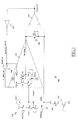
- Figure 7 illustrates a circuit diagram of a sensing circuit 700 according to a second embodiment of the present invention (the elements corresponding to those shown in Figures 1 and 3 are denoted with the same reference numerals).
- the precharge phase is not accomplished by exploiting the feedback current IF delivered by the amplifier 110 through the transistor D1 (that in this case is absent), but an auxiliary circuital branch (indicated with 710 in the Figure 7) is provided to this purpose, as explained in the following.
- Figure 7 illustrates the internal structure of the amplifier 110 in greater detail, showing its circuit diagram; the amplifier 100 is a differential amplifier with an active load formed by a current mirror. More in particular, the amplifier 110 includes an input differential pair formed by two (preferably native) NMOS transistors 715, 720 supplied by a biasing current generator IBIAS: the transistors 715, 720 have source terminals connected to a terminal of the biasing current generator IBIAS, forming a circuital node VL, and drain terminals connected to a PMOS current mirror formed by two (preferably native) PMOS transistors 725, 730.
- the transistor 715 has a gate terminal connected to the node YMS and the transistor 720 has a gate terminal receiving the reference voltage VREF.
- the transistor 725 has a drain terminal connected to the drain terminal of the transistor 715, a gate terminal connected to a gate terminal of the transistor 730, forming a circuital node VGP, and a source terminal connected to a drain terminal of a PMOS transistor 735.
- the transistor 730 has a drain terminal connected to the drain terminal of the transistor 720, a gate terminal connected to the drain terminal and a source terminal connected to a drain terminal of a PMOS transistor 740.
- the transistors 735, 740 have source terminals receiving the supply reference voltage Vcc.
- the transistors 725, 730 connected in such a way to form a current mirror, have the function of forming the active load of the amplifier 100
- the transistors 735 and 740 have the function of activating/deactivating the current flow through the transistors of the current mirror.
- the transistor 735 has a gate terminal receiving a signal C_PRECH
- the transistor 740 has a gate terminal receiving a latching signal DATALATCH indicative of the completion of the evaluation phase.
- the latching signal DATALATCH is provided by an output terminal of an inverter logic gate 745, having an input terminal connected to the output terminal SA-OUT of the comparator 120.
- the signal C_PRECH is provided by an output terminal of an OR logic gate 750, having an input terminal receiving the latching signal DATALATCH and a precharge signal PRECH, whose value indicates if the sensing circuit 700 is in the precharge phase or not.
- a current/voltage converter 705 includes only one diode-connected transistor (the transistor D2), in such a way that the feedback current IF can flow only from the node YMS to the output OUTDIF1 of the amplifier 110 (through the transistor D2), and not in the opposite direction.
- the auxiliary circuit branch 710 includes a diode-connected, preferably native, NMOS transistor 755 having a source terminal connected to a drain terminal of an NMOS transistor 760 and a drain and a gate terminals connected to the node YMS.
- the transistor 760 has a source terminal connected to the node VL of the amplifier 110 and a gate terminal receiving the precharge signal PRECH.
- the auxiliary circuit branch 710 further includes a preferably native PMOS transistor 765 having a drain terminal connected to the node YMS, a gate terminal connected to the node VGP of the amplifier 110 and a source terminal connected to the drain terminal of a PMOS transistor 770.
- the transistor 770 has a gate terminal receiving a signal PRECH_N which is the logical complement of the precharge signal PRECH, and a source terminal receiving the supply reference voltage Vcc.
- the PMOS transistors 765, 770 of the auxiliary circuit branch 710 are dimensioned in such a way to have higher transconductances compared to the NMOS transistors 755, 760.
- the auxiliary branch when the auxiliary branch is fully operative, i.e., during the precharge phase, when all the transistors 755, 760, 765 and 770 are on, the current flowing from the terminal providing the supply reference voltage Vcc to the node YMS through the transistors 765, 770 is higher than the current flowing from the node YMS to the terminal providing the ground voltage GND through the transistors 755, 760.
- the precharge signal PRECH is set to a high voltage value, for example equal to the supply reference voltage Vcc. In this way, the signal C_PRECH is driven to a high value too, and the transistor 735 of the amplifier 110 is turned off, so that the left circuit branch of the amplifier formed by the transistors 715, 725 and 735 is not crossed by any current. Therefore, all the current sunk by the biasing current generator IBIAS runs through the right circuit branch of the amplifier 110 ( i.e., through the transistors 720 and 730).
- the transistor 730 in order to be crossed by said current, causes its gate terminal (connected to the node VGP) to assume a low voltage value. Since the node VGP is connected to the gate terminal of the transistor 765, the latter transistor turns on, and a mirrored replica Ip of the current sunk by the transistor 730 starts flowing from the terminal providing the supply reference voltage Vcc to the node YMS through the transistors 765 and 770 (the signal PRECH_N is at the ground voltage GND). In other words, the left circuit branch of the amplifier 110 is replaced by the auxiliary branch 710 during the precharge phase, so as the capacitance of the node YMS is charged by the current Ip.
- the current Ip is higher (in absolute value) than the current In, in such a way that the intensity of the feedback current IF, flowing through the transistor D2 and the transistor 720, is positive.
- the voltage difference VR between the node YMS and the output OUTDIF1 of the amplifier 110 becomes quickly positive, sooner than in the previous cases, and the potential of the output SA-OUT of the comparator 120 switches high already at the beginning of the precharge phase.
- the latching signal DATALATCH switches low to the ground voltage GND, turning the transistor 740 on.
- the potential of the node YMS increases until it reaches the reference voltage VREF, and remains always higher than the potential of the output OUTDIF1.
- the precharge signal PRECH is switched low to the ground voltage GND, turning off the auxiliary branch 710 and activating the left circuit branch of the amplifier 110. Consequently, the transistors 715, 725 and 735 turn on, sinking a mirrored replica of the current sunk by the transistor 730. In this way, the amplifier 110 is in an operative condition adapted to carry out the evaluation phase (that is not described, being the evaluation phase equal to that previously described referring to the sensing circuit 300).
- the precharge signal PRECH switches, the potential of the node VL, and consequently of the node VGP, slightly increases in value for a transient, since the transistor 715 starts providing current thereto.
- the transistors 755 and 765 are dimensioned in such a way that the current flowing there through barely before the switching of the precharge signal PRECH is equal (or, at least, almost equal) to the current sunk by the transistors 715 and 725.
- the evaluation phase can be expediently initiated applying the voltage VRAMP to the control gate of the selected memory cell MC (thus reducing the duration of the precharge phase), taking advantage of the non-conductivity of the memory cell MC as long as the value reached by the voltage VRAMP is lower than the threshold voltage of the memory cell MC.
- the sensing circuit 700 has two main advantages.
- the node YMS is charged directly by the auxiliary circuit branch 710 with a constant current, without the need of being charged by the feedback current IF through the current/voltage converter 705. In this way, the time constant characterizing the charging process of the node YMS, that in the sensing circuit 300 is given by the capacitance of the node YMS multiplied by the resistance of the current/voltage converter, is definitely reduced.
- the output SA-OUT of the comparator 120 switches high before the potential of the node YMS has reached the reference voltage VREF.
- the precharge time is only limited by the time needed for bringing the potential of the node YMS to the reference voltage VREF, and not by the switching time of the output SA-OUT.
- both the sensing circuit 300 and the sensing circuit 700 have several advantages with respect the known sensing circuit 100 with the current/voltage converter consisting of a resistor R.
- both the sensing circuit 300 and the sensing circuit 700 are substantially less susceptible to disturbs, and they are less prone to reading errors in the evaluation phase, thanks to the particular nonlinear diode-like current/voltage characteristic with respect to the linear current/voltage characteristic of the resistor.
- the sensing circuit 700 is particularly designed in such a way to speed up the precharge phase, thanks to the presence of an auxiliary circuit branch having the purpose of charging the node YMS.
- both the sensing circuits 300 and 700 may result a little slower than the known sensing circuit 100, i.e., their switching instant SW occurs slightly later with respect the switching instant SW of the sensing circuit 100.
- the current IBL drained by the memory cell MC during the evaluation phase is slightly higher in the case of the sensing circuit 100 with the resistor R, since the discharge of the bit line capacitance is slower in the cases with diode-connected transistors (sensing circuits 300 and 700).
- the sensing circuit 100 once the current IBL has exceeded the reference current IREF, the voltage difference VR across the resistor R changes sign, and the feedback current IF starts to flow through the bit line BL. This does not occur in the sensing circuit 300, since the comparator 120 switches before the transistor D1 is activated (because of its threshold voltage).
- the second reason is the higher voltage difference VR between the node YMS and the output OUTDIF1 of the amplifier 110 at the end of the precharge phase in the sensing circuits 300 and 700.
- the inversion time IT occurs before in the sensing circuit 100.
- the same reasons that make the sensing circuits 300, 700 less susceptible to the disturbs may render the sensing circuits 300, 700 slightly slower (considering reference currents IREF of the same intensities) with respect to the sensing circuit 100.
- a modified version of the sensing circuit 700 is provided, including an additional current/voltage converter, as depicted in Figure 9.
- Figure 9 illustrates a sensing circuit 900 having a circuit structure similar to that of the sensing circuit 700 of Figure 7, with the addition of a further current/voltage converter 905 connected between the node YMS (coupling the bit line BL with the non-inverting input of the comparator 120 and the inverting input of the amplifier 110) and a node YMSS formed by the connection of the drain terminal of the transistor D2 with the current generator providing the reference current IREF and the auxiliary circuital branch 710.
- the current/voltage converter 905 includes a diode-connected NMOS transistors D3, having a drain terminal connected to the node YMSS, a source terminal connected to the node YMS and a gate terminal connected to the drain terminal.
- the transistor D3 is of the native type and has the same aspect ratio of the transistor D2.
- the switching instant SW of the sensing circuit 900 occurs before than in the case of the sensing circuits 300 and 700. This can be appreciated analyzing the behavior of the sensing circuit 900 during the evaluation phase.
- the potential of the node YMSS is almost equal to the potential of the node YMS, because the transistor D3 is almost turned off, and the voltage difference VC among the node YMSS and the node YMS is nearly zero.
- the potential of the node YMS decreases, but very slowly. This happens because the node YMS exhibits a heavy capacitive load, given by the stray capacitance associated with the bit line BL to which it is connected. Since the current IBL has to flow through the transistor D3, the transistor D3 is activated, generating a positive voltage difference VC across its terminals. Consequently, since the potential of the node YMS is almost clamped because of its heavy capacitive load, the potential of the node YMSS increases in a very fast way, accordingly increasing the potential of the output OUTDIF1 of the amplifier 110 in such a way to strongly speed the evaluation phase up.
- the inversion time IT will occurs when the voltage difference VR among the output OUTDIF1 of the amplifier 110 and the node YMS equals zero. Since the voltage difference VR is equal to the voltage difference VC among the node YMSS and the node YMS minus a voltage difference VR' between the drain terminal of the transistor D2 and its source terminal, the inversion time IT will occurs when the voltage difference VC reaches the voltage difference VR'.
- a capacitor MCAP having a first terminal connected to the node YMSS and a second terminal connected to the output OUTDIF1 of the amplifier 110 is provided.
- the capacitor MCAP may be for example implemented exploiting the gate capacitance of a native NMOS transistor.
- the sensing circuit 900 has the further advantage of being less susceptible to common-mode disturbs that may occurs at the input of the comparator 120.
- a fraction of the unavoidable disturbs affecting the potential of the output OUTDIF1 of the amplifier 110 are provided also to the node YMS.
- the concept of the present invention are also applicable if an amplifier 110 having a different circuit structure is used and/or when the auxiliary circuit branch 710 is differently implemented.
- diode-connected MOS transistors are used, this is not to be considered a limitation: other ways exists of providing elements behaving essentially like diodes, e.g., pn junction diodes, schocttky diodes etc.
Abstract
Description
- The present invention generally relates to semiconductor memories, either stand-alone or embedded in more complex integrated circuit electronic systems. In particular, the invention relates to an improved sensing circuit for a semiconductor memory.
- Semiconductor memories are commonly used in several applications for storing information, both temporarily (in the so-called volatile memories), and permanently (in the so-called non-volatile memories). Non-volatile memories are capable of retaining the stored information even in absence of a power supply source.
- Typically, a non-volatile semiconductor memory comprises a matrix of memory cells, e.g., floating gate MOS transistors; each memory cell has a threshold voltage adapted to be programmed to different levels, corresponding to different logic values.
- The so-called flash memory is a very popular type of non-volatile memory, which also exhibits the capability of electrically writing and erasing the memory cells.
- For example, each memory cell of a two-level flash memory is adapted to store a single information bit. In an erased condition, the generic memory cell has a relatively low threshold voltage (associated by convention with the logic value "1"); the memory cell is programmed by injecting electrons into its floating gate: in this condition the memory cell has a higher threshold voltage (associated by convention with the logic value "0").
- Multilevel flash memories comprise instead memory cells capable of storing more than just one information bit. Each memory cell can be programmed to one of a plurality of different states, each corresponding to a respective range of threshold voltage values. For example, each memory cell of a four-level flash memory stores a logic value consisting of two information bits ("11", "10", "01" e "00", with the logic value "11" that is associated with the lowest threshold voltage range and the logic value "00" that is associated with the highest threshold voltage range).
- In order to retrieve the stored information, semiconductor memories comprise reading circuits, adapted to read the data stored in the memory cells.
- Particularly, the data stored in the selected memory cell is read by comparing the behavior of the current flowing through the selected memory cell with the behavior of the current(s) provided by one or more reference cells which are programmed to predetermined states. For this purpose, the reading circuit has to properly bias the selected memory cell and the reference cells.
- The comparison between the currents flowing through the selected memory cell and the reference memory cells, respectively, is typically performed by sensing circuits, included in the reading circuit and adapted to generate output signals whose value provide an indication of the logic value stored in the selected memory cell.
- A known technique for reading the information stored in the memory cells is the so-called ramp-voltage sensing technique.
- Essentially, the ramp-voltage sensing technique comprises two different phases: a precharge phase and an evaluation phase. Before the evaluation phase of the datum stored in the selected memory cell, the precharge phase is required for precharging an access line (e.g., a bit line) coupled to the selected memory cell, to a predetermined potential, in such a way as to charge stray capacitances intrinsically associated therewith. In fact, a current flowing through the bit line causes the charging of the associated stray capacitances, and, accordingly, a corresponding transient is required before the bit line voltage and current reach a steady value. Thus, for avoiding a wrong reading performed during this transient, it is necessary to guarantee that the bit line charging is completed, before performing an evaluation on the logic value stored in the memory cell accessed for reading. Regretfully, the length of this transient depends on a number of factors, such as the operating temperature, the value of a supply voltage of the memory device, and statistical variations of parameters whose values are affected by the manufacturing process.
- According to the ramp-voltage sensing technique, the evaluation phase provides for applying a voltage ramp to the control gate of a selected memory cell to be read and to the reference memory cells (having known threshold voltages); the datum stored in the selected memory cell is determined on the basis of a time relationship between the instants at which the selected memory cell and the reference memory cells pass from a first conduction state to a second conduction state. In the practice, the first conduction state corresponds to a sunk current less than a predetermined current and the second conduction state corresponds to a sunk current equal to or exceeding the predetermined current. This sensing technique is particularly suited for the sensing of multi-level memory cells.
- A known sensing circuit used for performing both the precharge phase and the evaluation phase according to the ramp-voltage sensing technique is described in the
European patent application EP1505605 . - Figure 1 shows an exemplary circuit diagram of a known
sensing circuit 100 adapted to perform both the precharge and the evaluation according to the ramp-voltage sensing technique. Thesensing circuit 100 comprises anamplifier 110, particularly a differential amplifier of relatively high gain, having an inverting input (indicated by the symbol "-") and a non-inverting input (indicated by the symbol "+"). The inverting input of theamplifier 110 is connected to a circuital node YMS, that is coupled to a selected memory cell MC through a bit line BL. The non-inverting input is instead fed with a reference voltage VREF, having a desired predetermined value which is the target potential of the node YMS. A resistive load element R, typically, a polysilicon resistor, is connected in negative feedback between an output OUTDIF of theamplifier 110 and the inverting input thereof. The output OUTDIF1 of theamplifier 110 is also fed to an inverting input of acomparator 120, having a non-inverting input directly connected to the inverting input of theamplifier 110, and thus to the node YMS. An output of thecomparator 120 forms an output SA-OUT of thesensing circuit 100. The node YMS is also connected to a reference current generator, providing a reference current IREF to be exploited during the evaluation phase. - Figure 2 pictorially illustrates the evolution in time of the potentials of the node YMS, the output OUTDIF 1 and the output SA-OUT during both the precharge and evaluation phases.
- At the beginning of the precharge phase, the capacitance (not shown in the Figure) intrinsically associated with the bit line BL (and thus loading the node YMS) is assumed to be discharged, so the potential of the node YMS is low, approximately equal to a reference (ground) voltage GND. Since the voltage difference between the non-inverting input and the inverting input of the
amplifier 110 is positive (it is assumed that the reference voltage VREF is higher than the ground voltage GND), the potential of the output OUTDIF1 assumes a high positive value. Consequently, theamplifier 110 delivers a feedback current IF of relatively high intensity, flowing from the output OUTDIF1 to the node YMS through the resistor R. Also, the reference current IREF flows to the node YMS. In this way, the capacitance of the node YMS is charged, and the potential of the node YMS increases. As long as the potential of the node YMS is lower than the reference voltage VREF, the potential of the output OUTDIF1 is positive. Also, as long as the potential of the output OUTDIF1 is higher than the potential of the node YMS, the feedback current IF flows from the output OUTDIF1 to the node YMS, and the voltage difference between the non-inverting input and the inverting input of thecomparator 120 is negative. Consequently, during this period of time, the potential of the output SA-OUT of thecomparator 120 is low, for example at a value equal to the ground voltage GND. As the potential of the node YMS increases, the (absolute value of the) potential of the output OUTDIF1 and the (absolute value of the) feedback current IF decrease. - At the end of the precharge phase, the potential of the node YMS reaches the reference voltage VREF, and the feedback current IF starts flowing in the reverse direction, flowing from the node YMS to the output OUTDIF1. In this way, the voltage difference between the node YMS and the output OUTDIF1 is positive and the potential of the output SA-OUT of the
comparator 120 switches high, since the potential of its non-inverting terminal becomes higher than the potential of its inverting terminal. Moreover, after a transient, the feedback current IF equals the reference current IREF, and the potential of the node YMS is stable. In this steady-state condition, the voltage difference VR between the node YMS and the output OUTDIF1 is stable, with the node YMS at a potential higher than that of the output OUTDIF1. - Once the precharge phase is terminated, the evaluation phase is started by applying a voltage ramp to the control gate of the selected memory cell MC to be read and to the reference cells. When the voltage ramp reaches a sufficiently high value, the selected memory cell MC begins draining a current IBL from the node YMS, through the bit line BL. The feedback current IF still flows from the node YMS to the output OUTDIF1 but, since the reference current IREF is constant, as the current IBL increases, the (absolute value of the) feedback current IF decreases.
- When, due to the increase in the gate voltage, the current IBL reaches and exceeds the reference current IREF, the feedback current IF reverses its direction, flowing from the output OUTDIF1 to the node YMS and this in turn causes the reverse in the sign of the voltage difference VR across the resistor R. In fact, the potential of the output OUTDIF1 exceeds the potential of the node YMS at an inversion time IT, as depicted in Figure 2. In this way, the potential of the output SA-OUT of the
comparator 120 switches again low (e.g., to the ground voltage GND) at a switching instant SW right after the inversion time IT. The delay between the inversion time IT and the switching instant SW depends on the switching speed of thecomparator 120. - The switching instant SW of the
comparator 120 is then exploited for retrieving the datum stored into the selected memory cell MC: the higher the threshold voltage of the selected memory cell MC, the later the switching instant SW occurs. More in particular, the switching instant SW in respect of the selected cell to be read is compared to a switching instant SWREF for a reference memory cell having a known predetermined threshold voltage, determined using a sensing circuit identical to thecircuit 100. If the switching instant SW occurs before the switching instant SWREF, the threshold voltage of the selected memory cell MC is lower than the threshold voltage of the reference memory cell, and vice versa. - The Applicant has observed that the known
sensing circuit 100 for the ramp-voltage sensing technique described in the foregoing is affected by some problems. - First of all, the
sensing circuit 100 is very sensitive to variations of the reference current IREF and to disturbs affecting the reference voltage VREF, the potential of the node YMS and the potential of the output OUTDIF1. Since the inversion time IT (and the switching instant SW of the comparator 120) strongly depends on the voltage difference VR at the end of the precharge phase, the lower the intensity of the reference current IREF, the higher the sensitivity to the disturbs of thesensing circuit 100, because the voltage difference VR between the node YMS and the output OUTDIF1 is made smaller. Variations of the reference current IREF may delay or anticipate the switching instant SW, and consequently increase the uncertainty of the evaluation of the datum stored in the selected memory cell MC. - In order to make the
sensing circuit 100 less susceptible to disturbs, it is preferable operating with relatively high voltage differences VR. This means that, with the same reference current IREF, a resistor R having a higher resistance value is needed. - However, in order to integrate a polysilicon resistor R having a relatively high resistance value, a significant area within the semiconductor chip wherein the
sensing circuit 100 is integrated is wasted. Furthermore, the resistance values of polysilicon resistors are affected by mismatches, capable in this case of invalidating the evaluation phase and/or increasing the precharge phase duration. - Moreover, by increasing too much the resistance value of the resistor R, the duration of the precharge phase is unfavorably increased, because the intensity of the feedback current IF flowing from the output OUTDIF1 to the node YMS is reduced, and therefore the capacitance of the node YMS takes more time for being charged.
- Also, observing again Figure 2, it can be appreciated that the voltage difference VR between the node YMS and the output OUTDIF1 becomes smaller and smaller (in absolute value) during the final part of the evaluation phase. Consequently, even if a resistor R having a high resistance value is used (so as to obtain an increased voltage difference VR at the end of the precharge phase), a disturb occurring in the final part of the evaluation phase would significantly shift the inversion time IT.
- In view of the state of the art outlined in the foregoing, it has been an object of the present invention to provide an improved sensing circuit which were not affected by the problems of the known sensing circuits, in particular by the problems discussed above.
- This and other objects have been attained by means of a sensing circuit for sensing semiconductor memory cells as set forth in appended
claim 1. The sensing circuit is adapted to determine when a cell current flowing trough a selected memory cell exceeds a reference current during an evaluation phase of a sensing operation. The sensing circuit is adapted to be coupled to at least one selected memory cell through a respective bit line. The sensing circuit includes: an access circuit node adapted to be coupled to the bit line; precharging means adapted to be activated in a precharge phase of the sensing operation preceding the evaluation phase, so as to bring a voltage of said access circuit node to a reference voltage; a reference circuit node coupled to the access circuit node and arranged to receive the reference current. The sensing circuit further includes an evaluation circuit node coupled to the reference circuit node through a first current to voltage converter, adapted to sink a current flowing from the reference circuit node to the evaluation circuit node and to produce a corresponding voltage difference between the reference circuit node and the evaluation circuit node, wherein said current is nearly equal to the reference current substantially at the end of the precharge phase; comparator means are provided, adapted to compare the voltage of the access circuit node with the voltage of the evaluation circuit node and to provide a corresponding comparison signal whose time pattern indicates when the cell current exceeds the reference current. The first current to voltage converter is an electronic device having essentially the behavior of a diode. - The characterizing features of the present invention are set forth in the appended claims. The features and advantages of the invention will be best understood by reading the following detailed description of an exemplary, non-limitative embodiment thereof, to be read in conjunction with the accompanying drawings:
- Figure 1 illustrates a circuit diagram of a known sensing circuit adapted to be used in a ramp-voltage sensing of a memory cell;
- Figure 2 illustrates the evolution in time of the potentials of some circuit nodes of the sensing circuit of Figure 1;
- Figure 3 illustrates a circuit diagram of a sensing circuit according to a first embodiment of the present invention;
- Figure 4 shows by way of comparison current/voltage characteristics of a current/voltage converter included in the sensing circuit of Figure 3 and of a resistor;
- Figure 5 illustrates the evolution time of the potentials of some circuit nodes of the sense circuit of Figure 3;
- Figure 6 illustrates a circuit diagram of a reference current generator suitable to be employed in the sensing circuit of Figure 3;
- Figure 7 illustrates a circuit diagram of a sensing circuit according to a second embodiment of the present invention;
- Figure 8 illustrates the evolution in time of the potentials of some circuit nodes of the sense circuit of Figure 7; and
- Figure 9 illustrates a circuit diagram of a sensing circuit according to a third embodiment of the present invention.
- Referring to the drawings, Figure 3 illustrates the circuit diagram of a
sensing circuit 300 according to a first embodiment of the present invention (the elements corresponding to those shown in Figure 1 are denoted with the same reference numerals, and their explanation is omitted for the sake of brevity). Thesensing circuit 300 has essentially the same structure of thesensing circuit 100, exception made for the fact that the resistor R of thecircuit 100 is replaced by a current/voltage converter 310 which includes two elements behaving essentially like diodes, particularly two diode-connected NMOS transistors D1, D2, connected in parallel but in reverse direction. More particularly, the transistor D1 has a drain terminal connected to the output OUTDIF1 of theamplifier 110, a source terminal connected to the node YMS and a gate terminal connected to the drain terminal; the transistor D2 has a source terminal connected to the output OUTDIF1, a drain terminal connected to the node YMS and a gate terminal connected to the drain terminal. Preferably, both the transistor D1 and the transistor D2 are "native" transistors, i.e., they have relatively low threshold voltages, their channel regions being realized without the performance of an ion implantation or diffusion for adjusting the threshold voltage. - It is pointed out that nothing prevents from using PMOS transistors for realizing both the transistor D1 and the transistor D2, even if native PMOS are worse from the matching viewpoint.
- The operations performed by the
sensing circuit 300 are similar to those previously described for thesensing circuit 100. At the beginning of the precharge phase, when the potential of the node YMS has not yet reached the reference voltage VRIF, the feedback current IF flows from the output OUTDIF1 of theamplifier 110 to the node YMS through the transistor D1, acting as a forward-biased diode. At the same time, the transistor D2 is off (i.e., it behaves as a reversed-biased diode), because the voltage difference VR between the node YMS and the output OUTDIF1 is negative. At the end of the precharge phase, when the potential of the node YMS reaches and exceeds the reference voltage VREF, the feedback current IF reverses its direction, the transistor D2 turns on, and the transistors D1 turns off, since the voltage difference VR becomes positive. This condition (D2 on, D1 off) still persists during the evaluation phase, till the inversion time IT, when the voltage difference VR assumes again a negative value. More in particular, during the evaluation phase a voltage VRAMP is applied to the gate terminal of the selected memory cell MC. The value of the voltage VRAMP increases according to an increasing voltage ramp. When the voltage VRAMP reaches a sufficiently high value, the selected memory cell MC begins draining a current IBL from the node YMS, through the bit line BL. The value of such current IBL increases in time, as the voltage VRAMP increases. As previously described in respect of thesensing circuit 100, the feedback current IF still flows from the node YMS to the output OUTDIF1 (through the transistor D2) but, since the reference current IREF is constant, as the current IBL increases, the (absolute value of the) feedback current IF decreases. When the current IBL reaches the value of the reference current IREF, the feedback current IF reverses its direction, so as to respect the Kirchoff's current law at the node YMS. In this way, the transistor D1 turns on and the transistor D2 turns off (inversion time IT), and the potential of the output OUTDIF1 rises over the potential of the node YMS (i.e., the voltage difference VR assumes a negative value). Consequently, the potential of the output SA-OUT switches low (switching instant SW). - The diagram 400 of the figure 4 illustrates the current/
voltage characteristic 410 of the current/voltage converter 310 compared to the current/voltage characteristic 420 of a resistor (like the resistor R used in the knownsense circuit 100 of Figure 1). - More particularly, the diagram 400 has a first reference axis (abscissa) used for denoting the voltage difference VR across the node YMS (drain terminal of the transistor D2) and the output OUTDIF1 (drain terminal of the transistor D1); a second reference axis (ordinate) is instead used for denoting the feedback current IF (whose value is assumed to be positive when flowing from the
output OUTDIF 1 to the node YMS). The origin of the system, given by the intersection of the two reference axe, corresponds to the condition experienced at the ideal inversion time IT, when both the voltage difference VR and the feedback current IF are zero. - When the feedback current IF assumes low (both positive and negative) values, the current/
voltage converter 310 generates a voltage difference VR which is higher (in absolute value) than the voltage difference generated by the resistor R. Vice versa, when the feedback current IF assumes high (both positive and negative) values, the voltage difference VR is higher (in absolute value) in the case of the resistor R. - Comparing the current/
voltage characteristic 410 with the current/voltage characteristic 420 it can be observed that the use of the current/voltage converter 310 provides several advantages with respect to the use of the resistor R. - In fact, thanks to the particular shape of the current/
voltage characteristic 410, at the beginning of the precharge phase the feedback current IF flowing from the output OUTDIF1 of theamplifier 110 to the node YMS through the transistor D1 is higher compared with the case with the resistor R; in this way, the charging the capacitance of the node YMS is faster. At the end of the precharge phase, the value of the feedback current IF (flowing from the node YMS to theoutput OUTDIF 1 of theamplifier 110 through the transistor D2) is equal to that of the reference current IREF. This value is relatively small, and the voltage difference VR is higher compared to the case with the resistor R. In this way, thecomparator 120 is driven in a more advantageous way by a higher input voltage, as explained in the following. - The abovementioned features can be observed referring to Figure 5, which illustrates the simulated evolutions in time of the potentials of the node YMS and the output OUTDIF1 of the
amplifier 110 in thesensing circuit 300 during both the precharge and the evaluation phases. More in particular, it can be seen that the voltage difference VR between the node YMS and the output OUTDIF1 remains higher than in the case illustrated in Figure 2 for almost all the time. - During the evaluation phase, when the selected memory cell MC begins draining the current IBL, the potential of the node YMS tends to lower. In this way, the transistor D2 starts to turn off, decoupling the output OUTDIF1 from the node YMS, in such a way to speed up the variation of the output OUTDIF1. In fact, the evolution in time of the potential of the output OUTDIF1 in the proximity of the inversion time IT is steeper than in the case illustrated in Figure 2.
- This feature makes the
sensing circuit 300 less susceptible to disturbs, and, in particular, less susceptible to spurious and unpredictable variations of the reference current IREF. In fact, a different reference current IREF would vary the potential assumed by the output OUTDIF1 at the end of the precharge phase, varying in turn the inversion time IT and, consequently, the switching instant SW, possibly invalidating the reading of the datum stored in the memory cell. However, with the sensing circuit of Figure 3, thanks to the steep time trend of the potential of the output OUTDIF1, said variation of the inversion time IT is greatly reduced. - This can be explained referring back to the diagram 400 of Figure 4. The spurious variations of the reference current IREF cause the current/
voltage characteristics sensing circuit 100, since the current/voltage characteristic 420 of the resistor R has a linear trend, a shift thereof along the direction of the first reference axis would strongly alter the current/voltage conditions that determines the inversion time. On the contrary, in the case of thesensing circuit 300, in correspondence of feedback currents IF having low values (i.e., during the evaluation phase, in the proximity of the inversion time IT), the current/voltage characteristic 410 is rather "flat" trend, and this makes the voltage difference VR more stable with respect the current variations due to disturbs, because the effects provoked by shifting the current/voltage characteristic 410 along the direction of the first reference axis are strongly reduced. - Another advantage provided by the current/
voltage converter 310 is the possibility of reducing the occupation area within the semiconductor chip wherein thesensing circuit 300 is integrated. In fact, the two transistors D1 and D2 of the voltage/converter 310 occupy a silicon area that is about one third the area occupied by a polysilicon resistor. - Moreover, the behavior of the current/
voltage converter 310 can be easily trimmed in such a way as to operate during the precharge phase in a different manner with respect to the evaluation phase. More particularly, since the current/voltage converter 310 is formed by a first diode-connected transistors D1 which is mainly employed during the precharge phase, and a second diode-connected transistor D2 which is mainly employed during the evaluation phase, changing the aspect ratio of one of the two transistors D1, D2 with respect to the other allows to increase/decrease (for the same voltage difference VR) the intensity of the feedback current IF during either the precharge or evaluation phases. - Using diode-connected transistors for realizing the current/
voltage converter 310 allows to configure in a simple way the reference current IREF of thesensing circuit 300. In fact, while the intensity of the reference current IREF in thesensing circuit 100 has to be sufficiently high, so that the voltage difference VR across the terminals of the resistor R is high enough for being able to drive thecomparator 120 even in presence of disturbs, the voltage difference VR between the terminals of the current/voltage converter 310 of thesensing circuit 300 is relatively high even for low reference current IREF intensities, thanks to the peculiar shape of the current/voltage characteristic 410. This allows in turn to adjust the intensity of the reference current IREF in a simple way. - For example, Figure 6 illustrates an exemplary circuit diagram of a reference
current generator 600 capable of generating a reference current IREF having a trimmable intensity. More particularly, the referencecurrent generator 600 allows trimming the intensity of the reference current IREF by selecting it among three predetermined values (the number of discrete values is not per-se limitative). - For this purpose, the reference
current generator 600 includes a basecurrent generator 610 providing a base current IB having a relatively constant value. The base current IB is then provided to a current mirror structure including three current mirrors connected in parallel, each one formed by four PMOS transistors PLD(i), PLU(i), PRD(i) and PRU(i), (i=1 to 3). - More particularly, each transistor PLD(i) has a drain terminal connected to a first terminal of the base
current generator 610, a source terminal connected to the drain terminal of the transistor PLU(i) and a gate terminal connected to the first terminal of the basecurrent generator 610. Each transistor PLU(i) has a source terminal receiving a supply reference voltage Vcc and a gate terminal connected to a terminal providing the ground voltage GND. Moreover, each transistor PRD(i) has a drain terminal connected to the node YMS of thesensing circuit 300, a source terminal connected to a drain terminal of the transistor PRU(i) and a gate terminal connected to the gate terminal of the transistor PLD(i). The transistor PRU(i) has a source terminal receiving the supply reference voltage Vcc and a gate terminal receiving a corresponding enabling voltage signal EN(i), capable of selectively assuming the ground voltage GND or the supply reference voltage Vcc. - All the transistors PLD(i) and PRD(i) are assumed to be equal (i.e., they have the same aspect ratio); moreover, all the transistors PLU(i) and PRU(i) have the same aspect ratio (in particular, the transistors PLU(i) and PRU(i) may have the minimal channel length allowed by the manufacturing process used for integrating the sensing circuit). In this way, each circuit branch formed by the transistors PLU(i), PLD(i) is run through by a current IL(i) equal to one third of the base current IB.
- Each circuit branch formed by the transistors PRU(i) and PRD(i) can be activated or deactivated depending on the voltage assumed by the corresponding enabling voltage signal EN(i). If the enabling voltage signal EN(i) is low (at the ground voltage GND), the branch formed by the transistors PRU(i) and PRD(i) is activated, and the transistors are crossed by a mirrored replica IR(i) of the current IL(i). If instead the enabling voltage signal EN(i) is high (at the supply reference voltage Vcc), the transistor PRU(i) is off, and the current IR(i) is equal to zero.
- Since each branch formed by the transistors PRU(i) and PRD(i) is connected to the node YMS, the reference current IREF is equal to the sum of the currents IR(1), IR(2) and IR(3), and its intensity depends on configuration of the enabling voltage signals EN(i). Consequently, the reference current IREF may be set to be equal to IB/3 (only one branch is enabled), 2*IB/3 (two branch enabled) or to IB (all the three branches are enabled).
- Although using the current/
voltage converter 310 the charging of the capacitance of the node YMS is speeded up, since the feedback current IF flowing through the transistor D1 is higher than in the case of use of the resistor R, the precharge phase still results intrinsically rather slow. In fact, at the beginning of the precharge phase the potential of the output OUTDIF1 of theamplifier 110 is higher than that of the node YMS. In this phase the potential of the node YMS has to reach the reference voltage VREF; for this purpose theamplifier 110 delivers the feedback current IF for charging the capacitance of the node YMS (said capacitance has a relatively high value, since it comprises the capacitances of the bit line BL connected thereto). The node YMS is charged in a time depending on the value of the capacitance connected thereto and the resistance value of the current/voltage converter 310. The higher the (absolute value of the) feedback current IF, the faster the precharge phase. However, the feedback current IF intensity is limited by the maximum output current that theamplifier 110 is capable of delivering, i.e., by its output saturation current. - In order to overcome the abovementioned limitation, Figure 7 illustrates a circuit diagram of a
sensing circuit 700 according to a second embodiment of the present invention (the elements corresponding to those shown in Figures 1 and 3 are denoted with the same reference numerals). According to this embodiment, in which instead of the current/voltage 310 of Figure 3 a current/voltage converter 705 including only the transistor D2 is used, the precharge phase is not accomplished by exploiting the feedback current IF delivered by theamplifier 110 through the transistor D1 (that in this case is absent), but an auxiliary circuital branch (indicated with 710 in the Figure 7) is provided to this purpose, as explained in the following. - Figure 7 illustrates the internal structure of the
amplifier 110 in greater detail, showing its circuit diagram; theamplifier 100 is a differential amplifier with an active load formed by a current mirror. More in particular, theamplifier 110 includes an input differential pair formed by two (preferably native)NMOS transistors 715, 720 supplied by a biasing current generator IBIAS: thetransistors 715, 720 have source terminals connected to a terminal of the biasing current generator IBIAS, forming a circuital node VL, and drain terminals connected to a PMOS current mirror formed by two (preferably native)PMOS transistors transistor 715 has a gate terminal connected to the node YMS and the transistor 720 has a gate terminal receiving the reference voltage VREF. Thetransistor 725 has a drain terminal connected to the drain terminal of thetransistor 715, a gate terminal connected to a gate terminal of thetransistor 730, forming a circuital node VGP, and a source terminal connected to a drain terminal of a PMOS transistor 735. Thetransistor 730 has a drain terminal connected to the drain terminal of the transistor 720, a gate terminal connected to the drain terminal and a source terminal connected to a drain terminal of aPMOS transistor 740. Thetransistors 735, 740 have source terminals receiving the supply reference voltage Vcc. While thetransistors amplifier 100, thetransistors 735 and 740 have the function of activating/deactivating the current flow through the transistors of the current mirror. For this purpose, the transistor 735 has a gate terminal receiving a signal C_PRECH, and thetransistor 740 has a gate terminal receiving a latching signal DATALATCH indicative of the completion of the evaluation phase. - The latching signal DATALATCH is provided by an output terminal of an
inverter logic gate 745, having an input terminal connected to the output terminal SA-OUT of thecomparator 120. Moreover, the signal C_PRECH is provided by an output terminal of anOR logic gate 750, having an input terminal receiving the latching signal DATALATCH and a precharge signal PRECH, whose value indicates if thesensing circuit 700 is in the precharge phase or not. - As already mentioned, a current/
voltage converter 705 includes only one diode-connected transistor (the transistor D2), in such a way that the feedback current IF can flow only from the node YMS to the output OUTDIF1 of the amplifier 110 (through the transistor D2), and not in the opposite direction. - The
auxiliary circuit branch 710 includes a diode-connected, preferably native,NMOS transistor 755 having a source terminal connected to a drain terminal of anNMOS transistor 760 and a drain and a gate terminals connected to the node YMS. Thetransistor 760 has a source terminal connected to the node VL of theamplifier 110 and a gate terminal receiving the precharge signal PRECH. Theauxiliary circuit branch 710 further includes a preferablynative PMOS transistor 765 having a drain terminal connected to the node YMS, a gate terminal connected to the node VGP of theamplifier 110 and a source terminal connected to the drain terminal of aPMOS transistor 770. Thetransistor 770 has a gate terminal receiving a signal PRECH_N which is the logical complement of the precharge signal PRECH, and a source terminal receiving the supply reference voltage Vcc. ThePMOS transistors auxiliary circuit branch 710 are dimensioned in such a way to have higher transconductances compared to theNMOS transistors transistors transistors transistors - In order to explain how the
sensing circuit 700 operates during the precharge phase, reference will be now jointly made to Figure 7 and to Figure 8, the latter figure illustrating the evolution in time of the potentials of the node YMS, of the output OUTDIF1 of theamplifier 110 and of the output SA-OUT of thesensing circuit 700 during the precharge phase. - At the beginning of the precharge phase, when the potential of the node YMS is at the ground voltage GND, the precharge signal PRECH is set to a high voltage value, for example equal to the supply reference voltage Vcc. In this way, the signal C_PRECH is driven to a high value too, and the transistor 735 of the
amplifier 110 is turned off, so that the left circuit branch of the amplifier formed by thetransistors transistor 730, in order to be crossed by said current, causes its gate terminal (connected to the node VGP) to assume a low voltage value. Since the node VGP is connected to the gate terminal of thetransistor 765, the latter transistor turns on, and a mirrored replica Ip of the current sunk by thetransistor 730 starts flowing from the terminal providing the supply reference voltage Vcc to the node YMS through thetransistors 765 and 770 (the signal PRECH_N is at the ground voltage GND). In other words, the left circuit branch of theamplifier 110 is replaced by theauxiliary branch 710 during the precharge phase, so as the capacitance of the node YMS is charged by the current Ip. Since at the beginning of the precharge phase the potential of the node YMS is at the ground voltage GND, thetransistor 755 is off, and does not conduct any current. As the potential of the node YMS increases thanks to the current Ip that charges the parasitic capacitance, thetransistors 755 starts turning on, sinking a current In from the node YMS to the node VL. According to the Kirchoff's current law at the node YMS, the current balance is: IF+In = IREF+Ip, wherein the direction of the feedback current IF is assumed to be from the node YMS to the output OUTDIF1. However, thanks to the particular dimensioning of the transistors of theauxiliary circuit branch 710, and thanks to the values assumed by the potential of the node YMS, the current Ip is higher (in absolute value) than the current In, in such a way that the intensity of the feedback current IF, flowing through the transistor D2 and the transistor 720, is positive. In this way, the voltage difference VR between the node YMS and the output OUTDIF1 of theamplifier 110 becomes quickly positive, sooner than in the previous cases, and the potential of the output SA-OUT of thecomparator 120 switches high already at the beginning of the precharge phase. - Since the potential of the output SA-OUT is at the high value, the latching signal DATALATCH switches low to the ground voltage GND, turning the
transistor 740 on. Thus, during all the precharge phase, the potential of the node YMS increases until it reaches the reference voltage VREF, and remains always higher than the potential of the output OUTDIF1. - At the end of the precharge phase, the precharge signal PRECH is switched low to the ground voltage GND, turning off the
auxiliary branch 710 and activating the left circuit branch of theamplifier 110. Consequently, thetransistors transistor 730. In this way, theamplifier 110 is in an operative condition adapted to carry out the evaluation phase (that is not described, being the evaluation phase equal to that previously described referring to the sensing circuit 300). When the precharge signal PRECH switches, the potential of the node VL, and consequently of the node VGP, slightly increases in value for a transient, since thetransistor 715 starts providing current thereto. However, thetransistors transistors - It has to be underlined that during said transient the evaluation phase can be expediently initiated applying the voltage VRAMP to the control gate of the selected memory cell MC (thus reducing the duration of the precharge phase), taking advantage of the non-conductivity of the memory cell MC as long as the value reached by the voltage VRAMP is lower than the threshold voltage of the memory cell MC.
- The
sensing circuit 700 has two main advantages. - The node YMS is charged directly by the
auxiliary circuit branch 710 with a constant current, without the need of being charged by the feedback current IF through the current/voltage converter 705. In this way, the time constant characterizing the charging process of the node YMS, that in thesensing circuit 300 is given by the capacitance of the node YMS multiplied by the resistance of the current/voltage converter, is definitely reduced. - Moreover, the output SA-OUT of the
comparator 120 switches high before the potential of the node YMS has reached the reference voltage VREF. In this way, the precharge time is only limited by the time needed for bringing the potential of the node YMS to the reference voltage VREF, and not by the switching time of the output SA-OUT. - It has to be observed that both the
sensing circuit 300 and thesensing circuit 700 have several advantages with respect the knownsensing circuit 100 with the current/voltage converter consisting of a resistor R. In fact, both thesensing circuit 300 and thesensing circuit 700 are substantially less susceptible to disturbs, and they are less prone to reading errors in the evaluation phase, thanks to the particular nonlinear diode-like current/voltage characteristic with respect to the linear current/voltage characteristic of the resistor. Additionally, thesensing circuit 700 is particularly designed in such a way to speed up the precharge phase, thanks to the presence of an auxiliary circuit branch having the purpose of charging the node YMS. - However, regarding the evaluation phase, both the
sensing circuits sensing circuit 100, i.e., their switching instant SW occurs slightly later with respect the switching instant SW of thesensing circuit 100. - This occurs for two main reasons.
- Firstly, the current IBL drained by the memory cell MC during the evaluation phase is slightly higher in the case of the
sensing circuit 100 with the resistor R, since the discharge of the bit line capacitance is slower in the cases with diode-connected transistors (sensingcircuits 300 and 700). In fact, in thesensing circuit 100, once the current IBL has exceeded the reference current IREF, the voltage difference VR across the resistor R changes sign, and the feedback current IF starts to flow through the bit line BL. This does not occur in thesensing circuit 300, since thecomparator 120 switches before the transistor D1 is activated (because of its threshold voltage). - The second reason is the higher voltage difference VR between the node YMS and the output OUTDIF1 of the
amplifier 110 at the end of the precharge phase in thesensing circuits amplifier 110 is steeper in thesensing circuits 300 and 700 (as shown in Figure 5), the inversion time IT occurs before in thesensing circuit 100. - Practically, the same reasons that make the
sensing circuits sensing circuits sensing circuit 100. - In order to speed up the evaluation phase maintaining at the same time the beneficial features of the
sensing circuits sensing circuit 700 is provided, including an additional current/voltage converter, as depicted in Figure 9. - More particularly, Figure 9 illustrates a
sensing circuit 900 having a circuit structure similar to that of thesensing circuit 700 of Figure 7, with the addition of a further current/voltage converter 905 connected between the node YMS (coupling the bit line BL with the non-inverting input of thecomparator 120 and the inverting input of the amplifier 110) and a node YMSS formed by the connection of the drain terminal of the transistor D2 with the current generator providing the reference current IREF and the auxiliarycircuital branch 710. The current/voltage converter 905 includes a diode-connected NMOS transistors D3, having a drain terminal connected to the node YMSS, a source terminal connected to the node YMS and a gate terminal connected to the drain terminal. The transistor D3 is of the native type and has the same aspect ratio of the transistor D2. - With such additional current/
voltage converter 905, considering same reference currents IREF, the switching instant SW of thesensing circuit 900 occurs before than in the case of thesensing circuits sensing circuit 900 during the evaluation phase. - At the end of the precharge phase, the potential of the node YMSS is almost equal to the potential of the node YMS, because the transistor D3 is almost turned off, and the voltage difference VC among the node YMSS and the node YMS is nearly zero.
- During the evaluation phase, when the memory cell MC begins draining the current IBL, the potential of the node YMS decreases, but very slowly. This happens because the node YMS exhibits a heavy capacitive load, given by the stray capacitance associated with the bit line BL to which it is connected. Since the current IBL has to flow through the transistor D3, the transistor D3 is activated, generating a positive voltage difference VC across its terminals. Consequently, since the potential of the node YMS is almost clamped because of its heavy capacitive load, the potential of the node YMSS increases in a very fast way, accordingly increasing the potential of the output OUTDIF1 of the
amplifier 110 in such a way to strongly speed the evaluation phase up. - The inversion time IT will occurs when the voltage difference VR among the output OUTDIF1 of the
amplifier 110 and the node YMS equals zero. Since the voltage difference VR is equal to the voltage difference VC among the node YMSS and the node YMS minus a voltage difference VR' between the drain terminal of the transistor D2 and its source terminal, the inversion time IT will occurs when the voltage difference VC reaches the voltage difference VR'. - In order to make the voltage difference VR' between the drain terminal of the transistor D2 and its source terminal less susceptible to disturbs, a capacitor MCAP having a first terminal connected to the node YMSS and a second terminal connected to the output OUTDIF1 of the
amplifier 110 is provided. The capacitor MCAP may be for example implemented exploiting the gate capacitance of a native NMOS transistor. - The
sensing circuit 900 has the further advantage of being less susceptible to common-mode disturbs that may occurs at the input of thecomparator 120. In fact, thanks to the presence of the transistor D3, a fraction of the unavoidable disturbs affecting the potential of the output OUTDIF1 of theamplifier 110 are provided also to the node YMS. - It is pointed out that, even in this case, nothing prevents from using PMOS transistors for realizing both the transistor D2 and the transistor D3, even if native PMOS are worse from the matching viewpoint.
- Moreover, the concept of the present invention are also applicable if an
amplifier 110 having a different circuit structure is used and/or when theauxiliary circuit branch 710 is differently implemented. - It is also pointed out that although in the foregoing it has always been assumed that diode-connected MOS transistors are used, this is not to be considered a limitation: other ways exists of providing elements behaving essentially like diodes, e.g., pn junction diodes, schocttky diodes etc.
- Naturally, in order to satisfy local and specific requirements, a person skilled in the art may apply to the solution described above many modifications and alterations. Particularly, although the present invention has been described with a certain degree of particularity with reference to preferred embodiment(s) thereof, it should be understood that various omissions, substitutions and changes in the form and details as well as other embodiments are possible; moreover, it is expressly intended that specific elements and/or method steps described in connection with any disclosed embodiment of the invention may be incorporated in any other embodiment as a general matter of design choice.
Claims (10)
- A sensing circuit (300; 700; 900) for sensing semiconductor memory cells (MC) adapted to determine when a cell current (IBL) flowing trough a selected memory cell exceeds a reference current (IREF) during an evaluation phase of a sensing operation, the sensing circuit being adapted to be coupled to at least one selected memory cell through a respective bit line (BL) and including:an access circuit node (YMS) adapted to be coupled to the bit line;precharging means adapted to be activated in a precharge phase of the sensing operation preceding the evaluation phase, so as to bring a voltage of said access circuit node to a reference voltage (VREF);a reference circuit node (YMS; YMSS) coupled to the access circuit node and arranged to receive the reference current;an evaluation circuit node (OUTDIF1) coupled to the reference circuit node through a first current to voltage converter (D2), adapted to sink a current (IF) flowing from the reference circuit node to the evaluation circuit node and to produce a corresponding voltage difference (VR; VR') between the reference circuit node and the evaluation circuit node, wherein said current is nearly equal to the reference current substantially at the end of the precharge phase;comparator means (120) adapted to compare the voltage of the access circuit node with the voltage of the evaluation circuit node and to provide a corresponding comparison signal (SA-OUT) whose time pattern indicates when the cell current exceeds the reference current,characterized in that
the first current to voltage converter is an electronic device having essentially the behavior of a diode. - The sensing circuit (300; 700; 900) of claim 2, wherein said first current to voltage converter (D2) includes a diode-connected transistor having an anode terminal connected to the reference circuit node (YMS; YMSS) and a cathode terminal connected to the evaluation circuit node (OUTDIF1).
- The sensing circuit (300; 700; 900) of claim 1 or 2, further including a negative feedback loop crossed by the feedback current (IF) and adapted to control the voltage of the access circuit node (YMS) during the evaluation phase, said negative feedback loop comprising the first current to voltage converter (D2) and a differential amplifier (110) having an inverting input connected to the access circuit node (YMS), a non-inverting input receiving the reference voltage (VREF) and an output connected to the evaluation circuit node.
- The sensing circuit (300) of any one among claims 1-3, further including a second current to voltage converter (D1) connected between the evaluation circuit node (OUTDIF1) and the access circuit node (YMS) so as to be crossed by a first charging current (IF) flowing from the evaluation circuit node to the access circuit node during the precharge phase and to establish a corresponding voltage difference between the evaluation circuit node and the access circuit node;
- The sensing circuit (300) of claim 4, wherein said second current to voltage converter (D1) includes a diode-connected transistor having an anode terminal connected to the evaluation node (OUTDIF1) and a cathode terminal connected to the access circuit node (YMS).
- The sensing circuit (700; 900) of any one among claims 1-3, further including an auxiliary circuit branch (710) connected to the reference circuit node (YMS; YMSS) adapted to provide a second charging current (Ip-In) to the reference circuit node during the precharge phase.
- The sensing circuit (300; 700) of any one of the preceding claims, wherein the reference circuit node coincides with the access circuit node.
- The sensing circuit (900) of claim 6 further including a third current to voltage converter (D3) connected between the reference circuit node (YMSS) and the access circuit node (YMS).
- The sensing circuit (900) of claim 8, wherein the third current to voltage converter (D3) includes a diode-connected transistor having the anode connected to the reference circuit node (YMSS) and the cathode connected to the access circuit node (YMS).
- A sensing method for sensing threshold voltages of semiconductor memory cells, the method including the steps of:during a precharge phase, bringing a voltage of an access circuit node coupling the sense circuit to a selected memory cell to a reference voltage;during an evaluation phase, determining when a cell current flowing trough a selected memory cell exceeds a reference current, said determining including:characterized in thatproviding the reference current to a reference circuit node coupled to the access circuit node;converting a current flowing from the reference circuit node to an evaluation circuit node to a voltage difference between the reference circuit node and the evaluation circuit node, wherein said current is nearly equal to the reference current substantially at the end of the precharge phase;comparing the voltage of the access circuit node with the voltage of the evaluation circuit node and providing a corresponding comparison signal whose time pattern indicates when the cell current exceeds the reference current,
said converting is accomplished by means of an electronic device having essentially the behavior of a diode.
Priority Applications (2)
| Application Number | Priority Date | Filing Date | Title |
|---|---|---|---|
| EP06114228A EP1858027A1 (en) | 2006-05-19 | 2006-05-19 | A sensing circuit for semiconductor memories |
| US11/739,167 US7515493B2 (en) | 2006-05-19 | 2007-04-24 | Sensing circuit for semiconductor memories |
Applications Claiming Priority (1)
| Application Number | Priority Date | Filing Date | Title |
|---|---|---|---|
| EP06114228A EP1858027A1 (en) | 2006-05-19 | 2006-05-19 | A sensing circuit for semiconductor memories |
Publications (1)
| Publication Number | Publication Date |
|---|---|
| EP1858027A1 true EP1858027A1 (en) | 2007-11-21 |
Family
ID=37219405
Family Applications (1)
| Application Number | Title | Priority Date | Filing Date |
|---|---|---|---|
| EP06114228A Withdrawn EP1858027A1 (en) | 2006-05-19 | 2006-05-19 | A sensing circuit for semiconductor memories |
Country Status (2)
| Country | Link |
|---|---|
| US (1) | US7515493B2 (en) |
| EP (1) | EP1858027A1 (en) |
Cited By (1)
| Publication number | Priority date | Publication date | Assignee | Title |
|---|---|---|---|---|
| CN104217744A (en) * | 2013-06-04 | 2014-12-17 | 力旺电子股份有限公司 | Current sensing amplifier and sensing method thereof |
Families Citing this family (9)
| Publication number | Priority date | Publication date | Assignee | Title |
|---|---|---|---|---|
| CN101630532B (en) * | 2008-07-17 | 2012-07-11 | 上海华虹Nec电子有限公司 | Sensitive amplifier used for electrically erasable read only memory and realization method thereof |
| KR101105434B1 (en) * | 2009-03-02 | 2012-01-17 | 주식회사 하이닉스반도체 | Apparatus and method for evaluating a current sensing characteristic for a semicondoctor memory device |
| CN103794252B (en) | 2012-10-29 | 2018-01-09 | 硅存储技术公司 | Low-voltage current for sense amplifier refers to generator |
| JP5933479B2 (en) * | 2013-03-27 | 2016-06-08 | パナソニック株式会社 | Compensation circuit and compensation method |
| ITMI20131060A1 (en) | 2013-06-26 | 2014-12-27 | St Microelectronics Srl | NON-VOLATILE MEMORY DEVICE WITH IMPROVED READING CIRCUIT |
| US9542981B2 (en) * | 2013-08-21 | 2017-01-10 | Globalfoundries Inc. | Self-timed, single-ended sense amplifier |
| US9214203B2 (en) | 2014-02-12 | 2015-12-15 | Ememory Technology Inc. | Sensing apparatus and data sensing method thereof |
| TWI555021B (en) * | 2014-03-27 | 2016-10-21 | 力旺電子股份有限公司 | Sensing apparatus and data sensing method thereof |
| JP2020155183A (en) * | 2019-03-20 | 2020-09-24 | キオクシア株式会社 | Storage device |
Citations (3)
| Publication number | Priority date | Publication date | Assignee | Title |
|---|---|---|---|---|
| EP0479098A2 (en) | 1990-10-01 | 1992-04-08 | Nec Corporation | Random access memory device having high-speed sense amplifier circuit implemented by bipolar transistors |
| US6281713B1 (en) | 1998-12-28 | 2001-08-28 | Samsung Electronics Co., Ltd. | Current sense amplifiers having equalization circuits therin that inhibit signal oscillations during active modes |
| EP1505605A1 (en) | 2003-08-06 | 2005-02-09 | STMicroelectronics S.r.l. | Improved sensing circuit for a semiconductor memory including bit line precharging and discharging functions |
Family Cites Families (1)
| Publication number | Priority date | Publication date | Assignee | Title |
|---|---|---|---|---|
| JPH1166890A (en) * | 1997-08-12 | 1999-03-09 | Mitsubishi Electric Corp | Semiconductor integrated circuit device |
-
2006
- 2006-05-19 EP EP06114228A patent/EP1858027A1/en not_active Withdrawn
-
2007
- 2007-04-24 US US11/739,167 patent/US7515493B2/en active Active
Patent Citations (3)
| Publication number | Priority date | Publication date | Assignee | Title |
|---|---|---|---|---|
| EP0479098A2 (en) | 1990-10-01 | 1992-04-08 | Nec Corporation | Random access memory device having high-speed sense amplifier circuit implemented by bipolar transistors |
| US6281713B1 (en) | 1998-12-28 | 2001-08-28 | Samsung Electronics Co., Ltd. | Current sense amplifiers having equalization circuits therin that inhibit signal oscillations during active modes |
| EP1505605A1 (en) | 2003-08-06 | 2005-02-09 | STMicroelectronics S.r.l. | Improved sensing circuit for a semiconductor memory including bit line precharging and discharging functions |
Cited By (2)
| Publication number | Priority date | Publication date | Assignee | Title |
|---|---|---|---|---|
| CN104217744A (en) * | 2013-06-04 | 2014-12-17 | 力旺电子股份有限公司 | Current sensing amplifier and sensing method thereof |
| CN104217744B (en) * | 2013-06-04 | 2017-06-09 | 力旺电子股份有限公司 | Current sense amplifier and its method for sensing |
Also Published As
| Publication number | Publication date |
|---|---|
| US20070285999A1 (en) | 2007-12-13 |
| US7515493B2 (en) | 2009-04-07 |
Similar Documents
| Publication | Publication Date | Title |
|---|---|---|
| US7515493B2 (en) | Sensing circuit for semiconductor memories | |
| US7272059B2 (en) | Sensing circuit for a semiconductor memory | |
| JP3782628B2 (en) | Multi-bit memory cell data sensing device | |
| JP5052793B2 (en) | Memory device with ramp-like voltage bias structure based on current generator | |
| US6559627B2 (en) | Voltage regulator for low-consumption circuits | |
| US20150302922A1 (en) | Reference and sensing with bit line stepping method of memory | |
| EP0729633B1 (en) | Sense amplifier for non-volatile semiconductor memory | |
| US6154390A (en) | Sensing apparatus and method for fetching multi-level cell data | |
| US7826284B2 (en) | Sense amplifier circuit and method for semiconductor memories with reduced current consumption | |
| US5940322A (en) | Constant voltage generating circuit with improved line voltage control | |
| KR100198518B1 (en) | Semiconductor apparatus having the clamping circuit | |
| US7499333B2 (en) | Boost voltage generating circuit and method thereof | |
| US7508717B2 (en) | Reading circuit for semiconductor memory | |
| CN110211623B (en) | Power supply system of NOR FLASH memory cell array | |
| EP1400980A1 (en) | A circuit for biasing an input node of a sense amplifier with a pre-charging stage | |
| US7881129B2 (en) | High voltage regulator for non-volatile memory device | |
| JP4007457B2 (en) | Multi-level memory circuit with regulated read voltage | |
| US20090303803A1 (en) | Independent Bi-Directional Margin Control Per Level and Independently Expandable Reference Cell Levels for Voltage Mode Sensing | |
| EP1249841B1 (en) | Reading circuit and method for a multilevel non volatile memory | |
| KR100364428B1 (en) | High voltage regulation circuit | |
| US6198661B1 (en) | Sensing circuit for semiconductor device and sensing method using the same | |
| US7388793B2 (en) | Method for configuring a voltage regulator | |
| US6728141B2 (en) | Method and circuit for timing dynamic reading of a memory cell with control of the integration time | |
| KR102013633B1 (en) | Multi level memory device and its data sensing method | |
| JP2004362749A (en) | Apparatus and method of multi-level sensing in memory array |
Legal Events
| Date | Code | Title | Description |
|---|---|---|---|
| PUAI | Public reference made under article 153(3) epc to a published international application that has entered the european phase |
Free format text: ORIGINAL CODE: 0009012 |
|
| AK | Designated contracting states |
Kind code of ref document: A1 Designated state(s): AT BE BG CH CY CZ DE DK EE ES FI FR GB GR HU IE IS IT LI LT LU LV MC NL PL PT RO SE SI SK TR |
|
| AX | Request for extension of the european patent |
Extension state: AL BA HR MK YU |
|
| 17P | Request for examination filed |
Effective date: 20080515 |
|
| 17Q | First examination report despatched |
Effective date: 20080620 |
|
| AKX | Designation fees paid |
Designated state(s): DE FR GB IT |
|
| GRAP | Despatch of communication of intention to grant a patent |
Free format text: ORIGINAL CODE: EPIDOSNIGR1 |
|
| RAP1 | Party data changed (applicant data changed or rights of an application transferred) |
Owner name: STMICROELECTRONICS SRL |
|
| STAA | Information on the status of an ep patent application or granted ep patent |
Free format text: STATUS: THE APPLICATION IS DEEMED TO BE WITHDRAWN |
|
| 18D | Application deemed to be withdrawn |
Effective date: 20100126 |