EP1857739A2 - Sauerstofferschöpfungssensor - Google Patents
Sauerstofferschöpfungssensor Download PDFInfo
- Publication number
- EP1857739A2 EP1857739A2 EP07009672A EP07009672A EP1857739A2 EP 1857739 A2 EP1857739 A2 EP 1857739A2 EP 07009672 A EP07009672 A EP 07009672A EP 07009672 A EP07009672 A EP 07009672A EP 1857739 A2 EP1857739 A2 EP 1857739A2
- Authority
- EP
- European Patent Office
- Prior art keywords
- nozzle
- fluid
- fuel
- gas
- liquid
- Prior art date
- Legal status (The legal status is an assumption and is not a legal conclusion. Google has not performed a legal analysis and makes no representation as to the accuracy of the status listed.)
- Withdrawn
Links
- QVGXLLKOCUKJST-UHFFFAOYSA-N atomic oxygen Chemical compound [O] QVGXLLKOCUKJST-UHFFFAOYSA-N 0.000 title claims abstract description 14
- 239000001301 oxygen Substances 0.000 title claims abstract description 14
- 229910052760 oxygen Inorganic materials 0.000 title claims abstract description 14
- 239000007788 liquid Substances 0.000 claims abstract description 31
- 239000007789 gas Substances 0.000 claims abstract description 27
- 238000002485 combustion reaction Methods 0.000 claims abstract description 19
- 239000012530 fluid Substances 0.000 claims description 83
- 239000000446 fuel Substances 0.000 claims description 78
- 238000004891 communication Methods 0.000 claims description 19
- 230000008878 coupling Effects 0.000 claims description 3
- 238000010168 coupling process Methods 0.000 claims description 3
- 238000005859 coupling reaction Methods 0.000 claims description 3
- ATUOYWHBWRKTHZ-UHFFFAOYSA-N Propane Chemical compound CCC ATUOYWHBWRKTHZ-UHFFFAOYSA-N 0.000 description 27
- VNWKTOKETHGBQD-UHFFFAOYSA-N methane Chemical compound C VNWKTOKETHGBQD-UHFFFAOYSA-N 0.000 description 27
- XLYOFNOQVPJJNP-UHFFFAOYSA-N water Substances O XLYOFNOQVPJJNP-UHFFFAOYSA-N 0.000 description 21
- 239000003345 natural gas Substances 0.000 description 13
- 239000001294 propane Substances 0.000 description 13
- 239000003570 air Substances 0.000 description 9
- 238000010438 heat treatment Methods 0.000 description 7
- 239000000463 material Substances 0.000 description 5
- 230000000712 assembly Effects 0.000 description 4
- 238000000429 assembly Methods 0.000 description 4
- 239000002184 metal Substances 0.000 description 4
- 229910052751 metal Inorganic materials 0.000 description 4
- 230000008901 benefit Effects 0.000 description 3
- 238000004519 manufacturing process Methods 0.000 description 3
- 238000000034 method Methods 0.000 description 3
- 230000001105 regulatory effect Effects 0.000 description 3
- 239000000853 adhesive Substances 0.000 description 2
- 230000001070 adhesive effect Effects 0.000 description 2
- 229910045601 alloy Inorganic materials 0.000 description 2
- 239000000956 alloy Substances 0.000 description 2
- 238000004140 cleaning Methods 0.000 description 2
- 238000012423 maintenance Methods 0.000 description 2
- 235000009781 Myrtillocactus geometrizans Nutrition 0.000 description 1
- 240000009125 Myrtillocactus geometrizans Species 0.000 description 1
- 229910000831 Steel Inorganic materials 0.000 description 1
- 229910052782 aluminium Inorganic materials 0.000 description 1
- XAGFODPZIPBFFR-UHFFFAOYSA-N aluminium Chemical compound [Al] XAGFODPZIPBFFR-UHFFFAOYSA-N 0.000 description 1
- 239000012080 ambient air Substances 0.000 description 1
- 238000005266 casting Methods 0.000 description 1
- 239000000919 ceramic Substances 0.000 description 1
- 239000000470 constituent Substances 0.000 description 1
- 238000005520 cutting process Methods 0.000 description 1
- 230000007423 decrease Effects 0.000 description 1
- 230000001934 delay Effects 0.000 description 1
- 230000000881 depressing effect Effects 0.000 description 1
- 230000009977 dual effect Effects 0.000 description 1
- 229920001971 elastomer Polymers 0.000 description 1
- 238000009434 installation Methods 0.000 description 1
- 238000010030 laminating Methods 0.000 description 1
- 238000003754 machining Methods 0.000 description 1
- 238000002844 melting Methods 0.000 description 1
- 230000008018 melting Effects 0.000 description 1
- 150000002739 metals Chemical class 0.000 description 1
- 238000003801 milling Methods 0.000 description 1
- 238000000465 moulding Methods 0.000 description 1
- 238000004806 packaging method and process Methods 0.000 description 1
- 239000004033 plastic Substances 0.000 description 1
- 229920003023 plastic Polymers 0.000 description 1
- 239000005060 rubber Substances 0.000 description 1
- 239000010935 stainless steel Substances 0.000 description 1
- 229910001220 stainless steel Inorganic materials 0.000 description 1
- 230000003068 static effect Effects 0.000 description 1
- 239000010959 steel Substances 0.000 description 1
- 239000000126 substance Substances 0.000 description 1
- 238000004381 surface treatment Methods 0.000 description 1
- 229920003051 synthetic elastomer Polymers 0.000 description 1
- 239000005061 synthetic rubber Substances 0.000 description 1
- 238000003466 welding Methods 0.000 description 1
Images







Classifications
-
- F—MECHANICAL ENGINEERING; LIGHTING; HEATING; WEAPONS; BLASTING
- F23—COMBUSTION APPARATUS; COMBUSTION PROCESSES
- F23N—REGULATING OR CONTROLLING COMBUSTION
- F23N5/00—Systems for controlling combustion
- F23N5/003—Systems for controlling combustion using detectors sensitive to combustion gas properties
- F23N5/006—Systems for controlling combustion using detectors sensitive to combustion gas properties the detector being sensitive to oxygen
-
- F—MECHANICAL ENGINEERING; LIGHTING; HEATING; WEAPONS; BLASTING
- F23—COMBUSTION APPARATUS; COMBUSTION PROCESSES
- F23N—REGULATING OR CONTROLLING COMBUSTION
- F23N5/00—Systems for controlling combustion
- F23N5/02—Systems for controlling combustion using devices responsive to thermal changes or to thermal expansion of a medium
- F23N5/10—Systems for controlling combustion using devices responsive to thermal changes or to thermal expansion of a medium using thermocouples
- F23N5/107—Systems for controlling combustion using devices responsive to thermal changes or to thermal expansion of a medium using thermocouples using mechanical means, e.g. safety valves
Definitions
- Certain embodiments disclosed herein relate generally to oxygen depletion sensors, and relate more specifically to oxygen depletion sensors for use with a gas, liquid, or combination thereof.
- Oxygen depletion sensors are used in a variety of applications, including heat-producing devices.
- ODSs are used in many varieties of heaters, fireplaces, stoves, and other heat-producing devices which utilize pressurized, combustible fuels. Some such devices operate with liquid propane, while others operate with natural gas.
- ODSs, such devices, and certain other components thereof have various limitations and disadvantages.
- an apparatus comprises an oxygen depletion sensor (ODS) that comprises a thermocouple, a first nozzle configured to direct heat from combustion of a first gas, liquid, or combination thereof to the thermocouple, a second nozzle configured to direct heat from combustion of a second gas, liquid, or combination thereof to the thermocouple, and a first igniter.
- ODS oxygen depletion sensor
- Figure 1 is a perspective cutaway view of a portion of one embodiment of a heater configured to operate using either a first fuel source or a second fuel source.
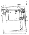
- Figure 2 is a perspective cutaway view of the heater of Figure 1.
- Figure 3 is a bottom perspective view of one embodiment of a pressure regulator configured to couple with either the first fuel source or the second fuel source.
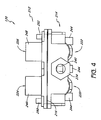
- Figure 4 is a back elevation view of the pressure regulator of Figure 3.
- Figure 5 is a bottom plan view of the pressure regulator of Figure 3.
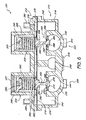
- Figure 6 is a cross-sectional view of the pressure regulator of Figure 3 taken along the line 6-6 in Figure 5.
- Figure 7 is a top perspective view of the pressure regulator of Figure 3.
- Figure 8 is a perspective view of one embodiment of a heat control valve.
- Figure 9 is a perspective view of one embodiment of a fluid flow controller comprising two valves.
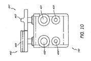
- Figure 10 is a bottom plan view of the fluid flow controller of Figure 9.
- Figure 11 is a cross-sectional view of the fluid flow controller of Figure 9.
- Figure 12 is a perspective view of one embodiment of a nozzle comprising two inputs, two outputs, and two pressure chambers.
- Figure 13 is a cross-sectional view of the nozzle of Figure 12 taken along the line 13-13 in Figure 14.
- Figure 14 is a top plan view of the nozzle of Figure 12.
- FIG. 15 is a perspective view of one embodiment of an oxygen depletion sensor (ODS) comprising two injectors and two nozzles.
- ODS oxygen depletion sensor
- Figure 16 is a front plan view of the ODS of Figure 15.
- Figure 17 is a top plan view of the ODS of Figure 15.
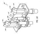
- Figure 18 is a perspective view of another embodiment of an ODS comprising two injectors and two nozzles.
- Figure 1 illustrates one embodiment of a heater 10.
- the heater 10 is a vent-free infrared heater, a vent-free blue flame heater, or some other variety of heater, such as a direct vent heater. Some embodiments include stoves, fireplaces, and gas logs. Other configurations are also possible for the heater 10.
- the heater 10 is configured to be mounted to a wall or a floor or to otherwise rest in a substantially static position. In other embodiments, the heater 10 is configured to move within a limited range. In still other embodiments, the heater 10 is portable.
- the heater 10 comprises a housing 20.
- the housing 20 can include metal or some other suitable material for providing structure to the heater 10 without melting or otherwise deforming in a heated environment.
- the housing 20 comprises a window 22 through which heated air and/or radiant energy can pass.
- the housing 20 comprises one or more intake vents 24 through which air can flow into the heater 10.
- the frame comprises outlet vents 26 through which heated air can flow out of the heater 10.
- the heater 10 includes a regulator 120.
- the regulator 120 is coupled with an output line or intake line, conduit, or pipe 122.
- the intake pipe 122 can be coupled with a heater control valve 130, which, in some embodiments, includes a knob 132.
- the heater control valve 130 is coupled to a fuel supply pipe 124 and an oxygen depletion sensor (ODS) pipe 126, each of which can be coupled with a fluid flow controller 140.
- ODS oxygen depletion sensor
- the fluid flow controller 140 is coupled with a first nozzle line 141, a second nozzle line 142, a first ODS line 143, and a second ODS line 144.
- the first and the second nozzle lines 141, 142 are coupled with a nozzle 160, and the first and the second ODS lines 143, 144 are coupled with an ODS 180.
- the ODS comprises a thermocouple 182, which can be coupled with the heater control valve 130, and an igniter line 184, which can be coupled with an igniter switch 186.
- Each of the pipes 122, 124, and 126 and the lines 141-144 can define a fluid passageway or flow channel through which a fluid can move or flow.
- the heater 10 comprises a combustion chamber 190.
- the ODS 180 is mounted to the combustion chamber 190, as shown in the illustrated embodiment.
- the nozzle 160 is positioned to discharge a fluid, which may be a gas, liquid, or combination thereof into the combustion chamber 190.
- a fluid which may be a gas, liquid, or combination thereof into the combustion chamber 190.
- gas or liquid hereafter shall also include the possibility of a combination of a gas and a liquid.
- the term "fluid” is a broad term used in its ordinary sense, and includes materials or substances capable of fluid flow, such as gases, liquids, and combinations thereof.
- either a first or a second fluid is introduced into the heater 10 through the regulator 120.
- the first or the second fluid proceeds from the regulator 120 through the intake pipe 122 to the heater control valve 130.
- the heater control valve 130 can permit a portion of the first or the second fluid to flow into the fuel supply pipe 124 and permit another portion of the first or the second fluid to flow into the ODS pipe 126, as described in further detail below.
- the first or the second fluid can proceed to the fluid flow controller 140.
- the fluid flow controller 140 is configured to channel the respective portions of the first fluid from the fuel supply pipe 124 to the first nozzle line 141 and from the ODS pipe 126 to the first ODS line 143 when the fluid flow controller 140 is in a first state, and is configured to channel the respective portions of the second fluid from the fuel supply pipe 124 to the second nozzle line 142 and from the ODS pipe 126 to the second ODS line 144 when the fluid flow controller 140 is in a second state.
- the fluid flow controller 140 when the fluid flow controller 140 is in the first state, a portion of the first fluid proceeds through the first nozzle line 141, through the nozzle 160 and is delivered to the combustion chamber 190, and a portion of the first fluid proceeds through the first ODS line 143 to the ODS 180. Similarly, when the fluid flow controller 140 is in the second state, a portion of the second fluid proceeds through the nozzle 160 and another portion proceeds to the ODS 180. As discussed in more detail below, other configurations are also possible.
- the regulator 120 desirably provides an adaptable and versatile system and mechanism which allows at least two fuel sources to be selectively and independently utilized with the heater 10.
- the fuel sources comprise natural gas and propane, which in some instances can be provided by a utility company or distributed in portable tanks or vessels.
- the heater 10 and/or the regulator 120 are preset at the manufacturing site, factory, or retailer to operate with selected fuel sources.
- the regulator 120 includes one or more caps 231 to prevent consumers from altering the pressure settings selected by the manufacturer.
- the heater 10 and/or the regulator 120 can be configured to allow an installation technician and/or user or customer to adjust the heater 10 and/or the regulator 120 to selectively regulate the heater unit for a particular fuel source.
- the regulator 120 comprises a first, upper, or top portion or section 212 sealingly engaged with a second, lower, or bottom portion or section 214.
- a flexible diaphragm 216 or the like is positioned generally between the two portions 212, 214 to provide a substantially airtight engagement and generally define a housing or body portion 218 of the second portion 212 with the housing 218 also being sealed from the first portion 212.
- the regulator 120 comprises more than one diaphragm 216 for the same purpose.
- first and second portions 212, 214 and diaphragm 216 comprise a plurality of holes or passages 228. In some embodiments, a number of the passages 228 are aligned to receive a pin, bolt, screw, or other fastener to securely and sealingly fasten together the first and second portions 212, 214.
- Other fasteners such as, but not limited to, clamps, locks, rivet assemblies, or adhesives may be efficaciously used.
- the regulator 120 comprises two selectively and independently operable pressure regulators or actuators 220 and 222 which are independently operated depending on the fuel source, such as, but not limited to, natural gas and propane.
- the first pressure regulator 220 comprises a first spring-loaded valve or valve assembly 224 and the second pressure regulator 222 comprises a second spring-loaded valve or valve assembly 226.
- the second portion 214 comprises a first fluid opening, connector, coupler, port, or inlet 230 configured to be coupled to a first fuel source. In further embodiments, the second portion 214 comprises a second fluid opening, connector, coupler, port, or inlet 232 configured to be coupled to a second fuel source. In some embodiments, the second connector 232 is threaded. In some embodiments, the first connector 230 and/or the first fuel source comprises liquid propane and the second fuel source comprises natural gas, or vice versa. The fuel sources can efficaciously comprise a gas, a liquid, or a combination thereof.
- the second portion 214 further comprises a third fluid opening, connector, port, or outlet 234 configured to be coupled with the intake pipe 122 of the heater 10.
- the connector 234 comprises threads for engaging the intake pipe 122. Other connection interfaces may also be used.
- the housing 218 of the second portion 214 defines at least a portion of a first input channel or passage 236, a second input channel or passage 238, and an output channel or passage 240.
- the first input channel 236 is in fluid communication with the first connector 230
- the second input channel 238 is in fluid communication with the second connector 232
- the output channel 240 is in fluid communication with the third connector 234.
- the output channel 240 is in fluid communication with a chamber 242 of the housing 218 and the intake pipe 122 of the heater 10.
- the input channels 236, 238 are selectively and independently in fluid communication with the chamber 242 and a fuel source depending on the particular fuel being utilized for heating.
- the second input connector 232 when the fuel comprises natural gas, the second input connector 232 is sealingly plugged by a plug or cap 233 (see Figure 7) while the first input connector 230 is connected to and in fluid communication with a fuel source that provides natural gas for combustion and heating.
- the cap 233 comprises threads or some other suitable fastening interface for engaging the connector 232.
- the natural gas flows in through the first input channel 236 into the chamber 242 and out of the chamber 242 through the output channel 240 and into the intake pipe 122 of the heater 10.
- the first input connector 230 is sealingly plugged by a the plug or cap 233 while the second input connector 232 is connected to and in fluid communication with a fuel source that provides propane for combustion and heating.
- the propane flows in through the second input channel 238 into the chamber 242 and out of the chamber 242 through the output channel 240 and into the intake pipe 122 of the heater 10.
- the cap 233 is coupled with either the first input connector 230 or the second input connector 232 prior to packaging or shipment of the heater 10, it can have the added advantage of helping consumers distinguish the first input connector 230 from the second input connector 232.
- the regulator 120 comprises a single input connector that leads to the first input channel 236 and the second input channel 238.
- a first pressurized source of liquid or gas or a second pressurized source of liquid or gas can be coupled with the same input connector.
- a valve or other device is employed to seal one of the first input channel 236 or the second input channel 238 while leaving the remaining desired input channel 236, 238 open for fluid flow.
- the second portion 214 comprises a plurality of connection or mounting members or elements 244 that facilitate mounting of the regulator 120 to a suitable surface of the heater 10.
- the connection members 244 can comprise threads or other suitable interfaces for engaging pins, bolts, screws, or other fasteners to securely mount the regulator 120.
- Other connectors or connecting devices such as, but not limited to, clamps, locks, rivet assemblies, and adhesives may be efficaciously used, as needed or desired.
- the first portion 212 comprises a first bonnet 246, a second bonnet 248, a first spring or resilient biasing member 250 positioned in the bonnet 246, a second spring or resilient biasing member 252 positioned in the bonnet 248, a first pressure adjusting or tensioning screw 254 for tensioning the spring 250, a second pressure adjusting or tensioning screw 256 for tensioning the spring 252 and first and second plunger assemblies 258 and 260 which extend into the housing 218 of the second portion 214.
- the springs 250, 252 comprise steel wire.
- at least one of the pressure adjusting or tensioning screws 254, 256 may be tensioned to regulate the pressure of the incoming fuel depending on whether the first or second fuel source is utilized.
- the appropriate pressure adjusting or tensioning screws 254, 256 are desirably tensioned by a predetermined amount at the factory or manufacturing facility to provide a preset pressure or pressure range. In other embodiments, this may be accomplished by a technician who installs the heater 10. In many embodiments, caps 231 are placed over the screws 254, 256 to prevent consumers from altering the preset pressure settings.
- the first plunger assembly 258 generally comprises a first diaphragm plate or seat 262 which seats the first spring 250, a first washer 264 and a movable first plunger or valve stem 266 that extends into the housing 218 of the second portion 214.
- the first plunger assembly 258 is configured to substantially sealingly engage the diaphragm 216 and extend through a first orifice 294 of the diaphragm 216.
- the first plunger 266 comprises a first shank 268 which terminates at a distal end as a first seat 270.
- the seat 270 is generally tapered or conical in shape and selectively engages a first O-ring or seal ring 272 to selectively substantially seal or allow the first fuel to flow through a first orifice 274 of the chamber 242 and/or the first input channel 236.
- the tensioning of the first screw 254 allows for flow control of the first fuel at a predetermined first pressure or pressure range and selectively maintains the orifice 274 open so that the first fuel can flow into the chamber 242, into the output channel 240 and out of the outlet 234 and into the intake pipe 122 of the heater 10 for downstream combustion. If the first pressure exceeds a first threshold pressure, the first plunger seat 270 is pushed towards the first seal ring 272 and seals off the orifice 274, thereby terminating fluid communication between the first input channel 236 (and the first fuel source) and the chamber 242 of the housing 218.
- the first pressure or pressure range and the first threshold pressure are adjustable by the tensioning of the first screw 254.
- the pressure selected depends at least in part on the particular fuel used, and may desirably provide for safe and efficient fuel combustion and reduce, mitigate, or minimize undesirable emissions and pollution.
- the first screw 254 may be tensioned to provide a first pressure in the range from about 3 inches of water column to about 6 inches of water column, including all values and sub-ranges therebetween.
- the first threshold or flow-terminating pressure is about 3 inches of water column, about 4 inches of water column, about 5 inches of water column, or about 6 inches of water column.
- the second inlet 232 is plugged or substantially sealed.
- the first pressure regulator 220 (and/or the first valve assembly 224) comprises a vent 290 or the like at the first portion 212.
- the vent can be substantially sealed, capped, or covered by a dustproof cap or cover, often for purposes of shipping. The cover is often removed prior to use of the regulator 120.
- the vent 290 is in fluid communication with the bonnet 246 housing the spring 250 and may be used to vent undesirable pressure build-up and/or for cleaning or maintenance purposes.
- the second plunger assembly 260 generally comprises a second diaphragm plate or seat 276 which seats the second spring 252, a second washer 278 and a movable second plunger or valve stem 280 that extends into the housing 218 of the second portion 214.
- the second plunger assembly 260 substantially sealingly engages the diaphragm 216 and extends through a second orifice 296 of the diaphragm 216.
- the second plunger 280 comprises a second shank 282 which terminates at a distal end as a second seat 284.
- the seat 284 is generally tapered or conical in shape and selectively engages a second O-ring or seal ring 286 to selectively substantially seal or allow the second fuel to flow through a second orifice 288 of the chamber 242 and/or the second input channel 238.
- the tensioning of the second screw 256 allows for flow control of the second fuel at a predetermined second pressure or pressure range and selectively maintains the orifice 288 open so that the second fuel can flow into the chamber 242, into the output channel 240 and out of the outlet 234 and into the intake pipe 122 of the heater 10 for downstream combustion. If the second pressure exceeds a second threshold pressure, the second plunger seat 284 is pushed towards the second seal ring 286 and seals off the orifice 288, thereby terminating fluid communication between the second input channel 238 (and the second fuel source) and the chamber 242 of the housing 218.
- the second pressure or pressure range and the second threshold pressure are adjustable by the tensioning of the second screw 256.
- the second screw 256 may be tensioned to provide a second pressure in the range from about 8 inches of water column to about 12 inches of water column, including all values and sub-ranges therebetween.
- the second threshold or flow-terminating pressure is about equal to 8 inches of water column, about 9 inches of water column, about 10 inches of water column, about 11 inches of water column, or about 12 inches of water column.
- the first inlet 230 is plugged or substantially sealed.
- the second pressure regulator 222 (and/or the second valve assembly 226) comprises a vent 292 or the like at the first portion 212.
- the vent can be substantially sealed, capped or covered by a dustproof cap or cover.
- the vent 292 is in fluid communication with the bonnet 248 housing the spring 252 and may be used to vent undesirable pressure build-up and/or for cleaning or maintenance purposes and the like.
- the first pressure, pressure range and threshold pressure are less than the second pressure, pressure range and threshold pressure. Stated differently, in some embodiments, when natural gas is the first fuel and propane is the second fuel, the second pressure, pressure range and threshold pressure are greater than the first pressure, pressure range and threshold pressure.
- the dual regulator 120 by comprising first and second pressure regulators 220, 222 and corresponding first and second valves or valve assemblies 224, 226, which are selectively and independently operable facilitates a single heater unit being efficaciously used with different fuel sources.
- This desirably saves on inventory costs, offers a retailer or store to stock and provide a single unit that is usable with more than one fuel source, and permits customers the convenience of readily obtaining a unit which operates with the fuel source of their choice.
- the particular fuel pressure operating range is desirably factory-preset to provide an adaptable and versatile heater.
- the pressure regulating device 120 can comprise a wide variety of suitably durable materials. These include, but are not limited to, metals, alloys, ceramics, plastics, among others. In one embodiment, the pressure regulating device 120 comprises a metal or alloy such as aluminum or stainless steel.
- the diaphragm 216 can comprise a suitable durable flexible material, such as, but not limited to, various rubbers, including synthetic rubbers. Various suitable surface treatments and finishes may be applied with efficacy, as needed or desired.
- the pressure regulating device 120 can be fabricated or created using a wide variety of manufacturing methods, techniques and procedures. These include, but are not limited to, casting, molding, machining, laser processing, milling, stamping, laminating, bonding, welding, and adhesively fixing, among others.
- regulator 120 has been described as being integrated in the heater 10, the regulator 120 is not limited to use with heating devices, and can benefit various other applications. Additionally, pressure ranges and/or fuel-types that are disclosed with respect to one portion of the regulator 120 can also apply to another portion of the regulator 120. For example, tensioning of either the first screw 254 or the second screw 256 can result in pressure ranges between about 3 inches of water column and about 6 inches of water column or between about 8 inches of water column and about 12 inches of water column, in some embodiments.
- the regulator 120 is configured to allow passage therethrough of either a first or a second fuel.
- the first or the second fuel passes through the intake pipe 122 to the heater control valve 130.
- the heater control valve 130 includes the knob 132.
- the heater control valve 130 can be coupled with the intake pipe 122, the fuel supply pipe 124 and the ODS pipe 126.
- the heater control valve 130 is coupled with the ODS thermocouple 182.
- the heater control valve 130 comprises a temperature sensor 300.
- the heater control valve 130 allows a portion of the first or the second fuel to pass from the intake pipe 122 to the fuel supply pipe 124 and another portion to pass to the ODS pipe 126.
- the amount of fuel passing through the heater control valve 130 is influenced by the settings of the knob 132 and/or the functioning of the thermocouple 182.
- the knob 132 is rotated by a user to select a desired temperature. Based on the temperature selected by the user and the temperature sensed by the temperature sensor 300, the heater control valve 130 can allow more or less fuel to pass to the fuel supply pipe 124.
- thermocouple 182 when a pilot light of the ODS heats the thermal couple 182, a current is generated in the thermocouple 182. In certain embodiments, this current produces a magnetic field within the heater control valve 130 that maintains the valve 130 in an open position. If the pilot light goes out or is disturbed, and the current flow is reduced or terminated, the magnetic field weakens or is eliminated, and the valve 130 closes, thereby preventing passage therethrough of the first or the second fuel.
- the first or the second fuel allowed through the heater control valve 130 proceeds to the fluid flow controller 140.
- the controller 140 comprises a housing 405, a first inlet 410, and a second inlet 420.
- the first inlet 410 is configured to couple with the fuel supply pipe 124 and the second inlet 420 is configured to couple with the ODS pipe 126.
- the fluid flow controller 140 comprises a first fuel supply outlet 431, and a second fuel supply outlet 432, a first ODS outlet 433, a second ODS outlet 434.
- the fluid flow controller 140 further comprises a first selector valve 441 and a second selector valve 442.
- a first selector control or knob 443 is coupled to the first selector valve 441 and a second selector knob 444 is coupled to the second selector valve 442.
- one of the first and second selector valves 441, 442 can be rotated within the housing via the first or second selector knob 443, 444, respectively.
- the second selector valve 442 is closed and the first selector valve 441 is opened such that fluid flowing through the fuel supply pipe 124 proceeds to the first fuel supply outlet 431 and into the first nozzle line 141 and fluid flowing through the ODS pipe 126 proceeds to the first ODS outlet 433 and into the first ODS line 143.
- the first selector valve 441 is closed and the second selector valve 442 is opened such that fluid flowing through the fuel supply pipe 124 proceeds to the second fuel supply outlet 432 and into the second nozzle line 142 and fluid flowing through the ODS pipe 126 proceeds to the second ODS outlet 434 and into the second ODS line 144.
- the fluid flow controller 140 can direct a first fluid to a first set of pipes 141, 143 leading to the nozzle 160 and the ODS 180, and can direct a second fluid to a second set of pipes 142, 144 leading to the nozzle 160 and the ODS 180.
- the nozzle 160 comprises an inner tube 610 and an outer tube 620.
- the inner tube 610 and the outer tube 620 can cooperate to form a body of the nozzle 160.
- the inner tube 610 and the outer tube 620 are separate pieces joined in substantially airtight engagement.
- the inner tube 610 and the outer tube 620 can be welded, glued, secured in threaded engagement, or otherwise attached or secured to each other.
- the inner tube 610 and the outer tube 620 are integrally formed of a unitary piece of material.
- the inner tube 610 and/or the outer tube 620 comprises a metal.
- the inner tube 610 and the outer tube 620 are elongated, substantially hollow structures. In some embodiments, a portion of the inner tube 610 extends inside the outer tube 620. As illustrated in Figures 13 and 14, in some embodiments, the inner tube 610 and the outer tube 620 can be substantially coaxial in some embodiments, and can be axially symmetric.
- the inner tube 610 comprises a connector sheath 612.
- the connector sheath 612 can comprise an inlet 613 having an area through which a fluid can flow.
- the connector sheath 612 is configured to couple with the second nozzle line 142, preferably in substantially airtight engagement.
- an inner perimeter of the connector sheath 612 is slightly larger than an outer perimeter of the second nozzle line 142 such that the connector sheath 612 can seat snugly over the second nozzle line 142.
- the connector sheath 612 is welded to the second nozzle line 142.
- an interior surface of the connector sheath 612 is threaded for coupling with a threaded exterior surface of the second nozzle line 142.
- the second nozzle line 142 is configured to fit over the connector sheath 612.
- the connector sheath 612 comprises a distal portion 614 that is configured to couple with the outer tube 620.
- each of the distal portion 614 of the inner tube 620 and a proximal portion 625 of the outer tube 620 comprises threads. Other attachment configurations are also possible.
- the nozzle 160 comprises a flange 616 that extends from the connector sheath 612.
- the flange 616 is configured to be engaged by a tightening device, such as a wrench, which can aid in securing the inner tube 610 to the outer tube 620 and/or in securing the nozzle 160 to the second nozzle line 142.
- the flange 624 comprises two or more substantially flat surfaces, and in other embodiments, is substantially hexagonal (as shown in Figures 12 and 14).
- the outer tube 620 comprises a shaped portion 627 that is configured to be engaged by a tightening device, such as a wrench.
- a tightening device such as a wrench.
- the shaped portion 627 is substantially hexagonal.
- the shaped portion 627 of the outer tube 620 and the flange 616 of the inner tube 610 can each be engaged by a tightening device such that the outer tube 620 and the inner tube 610 rotate in opposite directions about an axis of the nozzle 160.
- the inner tube 610 defines a substantially hollow cavity or pressure chamber 630.
- the pressure chamber 630 can be in fluid communication with the inlet 613 and an outlet 633.
- the outlet 633 defines an outlet area that is smaller than the area defined by the inlet 613.
- the pressure chamber 630 decreases in cross-sectional area toward a distal end thereof.
- the pressure chamber 630 comprises two or more substantially cylindrical surfaces having different radii.
- a single straight line is collinear with or runs parallel to the axis of each of the two or more substantially cylindrical surfaces.
- the outer tube 620 substantially surrounds a portion of the inner tube 610.
- the outer tube 620 can define an outer boundary of a hollow cavity or pressure chamber 640.
- an inner boundary of the pressure chamber 640 is defined by an outer surface of the inner tube 610.
- an outer surface of the pressure chamber 640 comprises two or more substantially cylindrical surfaces joined by substantially sloped surfaces therebetween.
- a single straight line is collinear with or runs parallel to the axis of each of the two or more substantially cylindrical surfaces.
- an inlet 645 and an outlet 649 are in fluid communication with the pressure chamber 640.
- the inlet 645 extends through a sidewall of the outer tube 620. Accordingly, in some instances, the inlet 645 generally defines an area through which a fluid can flow.
- the direction of flow of the fluid through the inlet 645 is nonparallel with the direction of flow of a fluid through the inlet 613 of the inner tube 610.
- an axial line through the inlet 645 is at an angle with respect to an axial line through the inlet 613.
- the inlet 645 can be configured to be coupled with the first nozzle line 141, preferably in substantially airtight engagement.
- an inner perimeter of the inlet 645 is slightly larger than an outer perimeter of the first nozzle line 141 such that the inlet 645 can seat snugly over the first nozzle line 141.
- the outer tube 620 is welded to the first nozzle line 141.
- the outlet 649 of the outer sheath 620 defines an area smaller than the area defined by the inlet 645. In some embodiments, the area defined by the outlet 649 is larger than the area defined by the outlet defined by the outlet 613 of the inner tube 610. In some embodiments, the outlet 613 of the inner tube 610 is within the outer tube 620. In other embodiments, the inner tube 610 extends through the outlet 649 such that the outlet 613 of the inner tube 610 is outside the outer tube 620.
- a fluid exits the second nozzle line 142 and enters the pressure chamber 630 of the inner tube 610 through the inlet 613.
- the fluid proceeds through the outlet 633 to exit the pressure chamber 630.
- the fluid further proceeds through a portion of the pressure chamber 640 of the outer tube 620 before exiting the nozzle 160 through the outlet 649.
- a fluid exits the first nozzle line 142 and enters the pressure chamber 640 of the outer tube 620 through the inlet 645.
- the fluid proceeds through the outlet 633 to exit the pressure chamber 640 and, in many embodiments, exit the nozzle 160.
- a fluid exiting the second nozzle line 142 and traveling through the pressure chamber 630 is at a higher pressure than a fluid exiting the first nozzle line 141 and traveling through the pressure chamber 640.
- liquid propane travels through the pressure chamber 630, and in other embodiments, natural gas travels through the pressure chamber 640.
- the ODS 180 comprises a thermocouple 182, a first nozzle 801, a second nozzle 802, a first electrode 808, and a second electrode 809.
- the ODS 180 comprises a first injector 811 coupled with the first ODS line 143 (see Figures 1 and 2) and the first nozzle 801 and a second injector 812 coupled with the second ODS line 144 (see Figures 1 and 2) and the second nozzle 802.
- the first and second injectors 811, 812 are standard injectors as are known in the art, such as injectors that can be utilized with liquid propane or natural gas.
- the ODS 180 comprises a frame 820 for positioning the constituent parts of the ODS 180.
- the first nozzle 801 and the second nozzle 802 are directed toward the thermocouple such that a stable flame exiting either of the nozzles 801, 802 will heat the thermocouple 182.
- the first nozzle 801 and the second nozzle 802 are directed to different sides of the thermocouple 182.
- the first nozzle 801 and the second nozzle 802 are directed to opposite sides of the thermocouple 182.
- the first nozzle 801 is spaced at a greater distance from the thermocouple than is the second nozzle 802.
- the first nozzle 801 comprises a first air inlet 821 at a base thereof and the second nozzle 802 comprises a second air inlet 822 at a base thereof.
- the first air inlet 821 is larger or smaller than the second air inlet 822.
- the first and second injectors 811, 812 are also located at a base of the nozzles 801, 802.
- a gas or a liquid flows from the first ODS line 143 through the first injector 811, through the first nozzle 801, and toward the thermocouple 182.
- a gas or a liquid flows from the second ODS line 144 through the second injector 812, through the second nozzle 802, and toward the thermocouple 182. In either case, the fluid flows near the first or second air inlets 821, 822, thus drawing in air for mixing with the fluid.
- the first injector 811 introduces a fluid into the first nozzle 801 at a first flow rate
- the second injector 812 introduces a fluid into the second nozzle 802 at a second flow rate.
- the first flow rate is greater than or less than the second flow rate.
- the first electrode 808 is positioned at an approximately equal distance from an output end of the first nozzle 801 and an output end of the second nozzle 802. In some embodiments, a single electrode is used to ignite fuel exiting either the first nozzle 801 or the second nozzle 802. In other embodiments, a first electrode 808 is positioned closer to the first nozzle 801 than to the second nozzle 802 and the second electrode 809 is positioned nearer to the second nozzle 802 than to the first nozzle 801.
- a user can activate the electrode by depressing the igniter switch 186 (see Figure 2).
- the electrode can comprise any suitable device for creating a spark to ignite a combustible fuel.
- the electrode is a piezoelectric igniter.
- igniting the fluid flowing through one of the first or second nozzles 801, 802 creates a pilot flame.
- the first or the second nozzle 801, 802 directs the pilot flame toward the thermocouple such that the thermocouple is heated by the flame, which, as discussed above, permits fuel to flow through the heat control valve 130.
- FIG 18 illustrates another embodiment of the ODS 180'.
- the ODS 180' comprises a single electrode 808.
- each nozzle 801, 802 comprises an first opening 851 and a second opening 852.
- the first opening 851 is directed toward a thermocouple 182'
- the second opening 852 is directed substantially away from the thermocouple 182'.
- the ODS 180 provides a steady pilot flame that heats the thermocouple 182 unless the oxygen level in the ambient air drops below a threshold level.
- the threshold oxygen level is between about 18 percent and about 18.5 percent.
- the pilot flame moves away from the thermocouple, the thermocouple cools, and the heat control valve 130 closes, thereby cutting off the fuel supply to the heater 10.
Landscapes
- Engineering & Computer Science (AREA)
- Chemical & Material Sciences (AREA)
- Combustion & Propulsion (AREA)
- Mechanical Engineering (AREA)
- General Engineering & Computer Science (AREA)
- Feeding And Controlling Fuel (AREA)
- Measuring Temperature Or Quantity Of Heat (AREA)
- Investigating Or Analyzing Non-Biological Materials By The Use Of Chemical Means (AREA)
Applications Claiming Priority (2)
| Application Number | Priority Date | Filing Date | Title |
|---|---|---|---|
| US80158706P | 2006-05-17 | 2006-05-17 | |
| US11/443,492 US7434447B2 (en) | 2006-05-17 | 2006-05-30 | Oxygen depletion sensor |
Publications (2)
| Publication Number | Publication Date |
|---|---|
| EP1857739A2 true EP1857739A2 (de) | 2007-11-21 |
| EP1857739A3 EP1857739A3 (de) | 2012-05-09 |
Family
ID=38283205
Family Applications (1)
| Application Number | Title | Priority Date | Filing Date |
|---|---|---|---|
| EP07009672A Withdrawn EP1857739A3 (de) | 2006-05-17 | 2007-05-15 | Sauerstofferschöpfungssensor |
Country Status (1)
| Country | Link |
|---|---|
| EP (1) | EP1857739A3 (de) |
Cited By (1)
| Publication number | Priority date | Publication date | Assignee | Title |
|---|---|---|---|---|
| CN104913373A (zh) * | 2015-06-09 | 2015-09-16 | 傅国红 | 一种自适应式双气源燃气取暖器 |
Family Cites Families (5)
| Publication number | Priority date | Publication date | Assignee | Title |
|---|---|---|---|---|
| US2319676A (en) * | 1940-05-09 | 1943-05-18 | Milwaukee Gas Specialty Co | Safety shutoff system |
| US2443892A (en) * | 1945-09-21 | 1948-06-22 | Robertshaw Fulton Controls Co | Safety control and ignition apparatus for gaseous fuel burners |
| US5397233A (en) * | 1993-08-10 | 1995-03-14 | Appalachian Stove & Fabricators, Inc. | Assembly for controlling the flow of gas for gas fired artificial logs |
| US5807098A (en) * | 1996-04-26 | 1998-09-15 | Desa International, Inc. | Gas heater with alarm system |
| JP4604269B2 (ja) * | 2001-08-08 | 2011-01-05 | パロマ工業株式会社 | ガス燃焼器具 |
-
2007
- 2007-05-15 EP EP07009672A patent/EP1857739A3/de not_active Withdrawn
Non-Patent Citations (1)
| Title |
|---|
| None |
Cited By (2)
| Publication number | Priority date | Publication date | Assignee | Title |
|---|---|---|---|---|
| CN104913373A (zh) * | 2015-06-09 | 2015-09-16 | 傅国红 | 一种自适应式双气源燃气取暖器 |
| CN104913373B (zh) * | 2015-06-09 | 2017-10-20 | 傅国红 | 一种自适应式双气源燃气取暖器 |
Also Published As
| Publication number | Publication date |
|---|---|
| EP1857739A3 (de) | 2012-05-09 |
Similar Documents
| Publication | Publication Date | Title |
|---|---|---|
| US7607426B2 (en) | Dual fuel heater | |
| US7730765B2 (en) | Oxygen depletion sensor | |
| US7677236B2 (en) | Heater configured to operate with a first or second fuel | |
| US20070277803A1 (en) | Heater | |
| US7654820B2 (en) | Control valves for heaters and fireplace devices | |
| US20080153045A1 (en) | Control valves for heaters and fireplace devices | |
| US8152515B2 (en) | Fuel selectable heating devices | |
| US8752541B2 (en) | Heating system | |
| US20130098349A1 (en) | Dual fuel heater with selector valve | |
| WO2012138764A2 (en) | Heating system | |
| US20150233883A1 (en) | Heating system |
Legal Events
| Date | Code | Title | Description |
|---|---|---|---|
| PUAI | Public reference made under article 153(3) epc to a published international application that has entered the european phase |
Free format text: ORIGINAL CODE: 0009012 |
|
| AK | Designated contracting states |
Kind code of ref document: A2 Designated state(s): AT BE BG CH CY CZ DE DK EE ES FI FR GB GR HU IE IS IT LI LT LU LV MC MT NL PL PT RO SE SI SK TR |
|
| AX | Request for extension of the european patent |
Extension state: AL BA HR MK YU |
|
| RAP1 | Party data changed (applicant data changed or rights of an application transferred) |
Owner name: CONTINENTAL APPLIANCES, INC. D.B.A. PROCOM |
|
| RIN1 | Information on inventor provided before grant (corrected) |
Inventor name: DENG DAVID |
|
| PUAL | Search report despatched |
Free format text: ORIGINAL CODE: 0009013 |
|
| AK | Designated contracting states |
Kind code of ref document: A3 Designated state(s): AT BE BG CH CY CZ DE DK EE ES FI FR GB GR HU IE IS IT LI LT LU LV MC MT NL PL PT RO SE SI SK TR |
|
| AX | Request for extension of the european patent |
Extension state: AL BA HR MK RS |
|
| RIC1 | Information provided on ipc code assigned before grant |
Ipc: F23N 5/10 20060101ALI20120330BHEP Ipc: F23N 5/00 20060101AFI20120330BHEP |
|
| 17P | Request for examination filed |
Effective date: 20121107 |
|
| AKX | Designation fees paid |
Designated state(s): AT BE BG CH CY CZ DE DK EE ES FI FR GB GR HU IE IS IT LI LT LU LV MC MT NL PL PT RO SE SI SK TR |
|
| 17Q | First examination report despatched |
Effective date: 20130319 |
|
| RAP1 | Party data changed (applicant data changed or rights of an application transferred) |
Owner name: PROCOM HEATING, INC. |
|
| GRAP | Despatch of communication of intention to grant a patent |
Free format text: ORIGINAL CODE: EPIDOSNIGR1 |
|
| INTG | Intention to grant announced |
Effective date: 20140313 |
|
| STAA | Information on the status of an ep patent application or granted ep patent |
Free format text: STATUS: THE APPLICATION IS DEEMED TO BE WITHDRAWN |
|
| 18D | Application deemed to be withdrawn |
Effective date: 20140724 |