EP1857675A1 - Variable displacement compressor - Google Patents
Variable displacement compressor Download PDFInfo
- Publication number
- EP1857675A1 EP1857675A1 EP06714184A EP06714184A EP1857675A1 EP 1857675 A1 EP1857675 A1 EP 1857675A1 EP 06714184 A EP06714184 A EP 06714184A EP 06714184 A EP06714184 A EP 06714184A EP 1857675 A1 EP1857675 A1 EP 1857675A1
- Authority
- EP
- European Patent Office
- Prior art keywords
- arm
- swash plate
- rotating member
- drive shaft
- tilting member
- Prior art date
- Legal status (The legal status is an assumption and is not a legal conclusion. Google has not performed a legal analysis and makes no representation as to the accuracy of the status listed.)
- Withdrawn
Links
- 238000006073 displacement reaction Methods 0.000 title claims abstract description 21
- 230000007246 mechanism Effects 0.000 claims abstract description 23
- 230000008859 change Effects 0.000 claims description 3
- 238000012986 modification Methods 0.000 description 8
- 230000004048 modification Effects 0.000 description 8
- 238000006243 chemical reaction Methods 0.000 description 7
- 230000006835 compression Effects 0.000 description 7
- 238000007906 compression Methods 0.000 description 7
- 238000004519 manufacturing process Methods 0.000 description 5
- 230000007423 decrease Effects 0.000 description 3
- 238000007599 discharging Methods 0.000 description 3
- 238000000034 method Methods 0.000 description 3
- 230000008569 process Effects 0.000 description 3
- 239000003507 refrigerant Substances 0.000 description 3
- 238000012546 transfer Methods 0.000 description 3
- 230000000694 effects Effects 0.000 description 2
- 238000000605 extraction Methods 0.000 description 2
- 238000005299 abrasion Methods 0.000 description 1
- 238000007796 conventional method Methods 0.000 description 1
- 238000003780 insertion Methods 0.000 description 1
- 230000000149 penetrating effect Effects 0.000 description 1
- 238000012545 processing Methods 0.000 description 1
- 238000010791 quenching Methods 0.000 description 1
- 230000000171 quenching effect Effects 0.000 description 1
- 238000007789 sealing Methods 0.000 description 1
Images




Classifications
-
- F—MECHANICAL ENGINEERING; LIGHTING; HEATING; WEAPONS; BLASTING
- F04—POSITIVE - DISPLACEMENT MACHINES FOR LIQUIDS; PUMPS FOR LIQUIDS OR ELASTIC FLUIDS
- F04B—POSITIVE-DISPLACEMENT MACHINES FOR LIQUIDS; PUMPS
- F04B27/00—Multi-cylinder pumps specially adapted for elastic fluids and characterised by number or arrangement of cylinders
- F04B27/08—Multi-cylinder pumps specially adapted for elastic fluids and characterised by number or arrangement of cylinders having cylinders coaxial with, or parallel or inclined to, main shaft axis
- F04B27/10—Multi-cylinder pumps specially adapted for elastic fluids and characterised by number or arrangement of cylinders having cylinders coaxial with, or parallel or inclined to, main shaft axis having stationary cylinders
- F04B27/1036—Component parts, details, e.g. sealings, lubrication
- F04B27/1054—Actuating elements
- F04B27/1072—Pivot mechanisms
Definitions
- the present invention relates to a variable displacement compressor having a linkage mechanism.
- a variable displacement compressor includes a drive shaft, a rotor that is fixed to the drive shaft and rotates integrally with the drive shaft, a swash plate (cam plate) that is attached to the drive shaft and changeable its tilt with respect to the axis of the drive shaft, a linkage mechanism that links the rotor and the swash plate, and pistons that are engaged to the swash plate.
- the drive shaft rotates
- the swash plate rotates with the rotor and the piston reciprocates corresponding to the inclination angle of the swash plate.
- the linkage mechanism links the rotor and the swash plate so that the inclination angle of the swash plate can be changed as transferring the rotation of the rotor to the swash plate.
- the piston strokes are changed by changing the inclination angle of the swash plate so as to change the discharging amount (see Japanese Patent Laid-Open No. 2004-068756 , for example).
- the conventional linkage mechanism includes a projection extending from the rotor toward the swash plate and a projection extending from the swash plate toward the rotor.
- the projection of the rotor and the projection of the swash plate overlap each other in the rotating direction and, with this structure, rotary torque from the rotor is transferred to the swash plate.
- the projection of the swash plate slidably contacts with a base of the projection of the rotor.
- the base of the projection of the rotor functions an axial direction load receiving face for receiving an axial direction load applied to the swash plate.
- the inclination angle of the swash plate changes with the slide of the projection of the swash plate on the pressure receiving face.
- the inclination angle of the swash plate is changed while a large compression reaction force (the axial direction load) from the pistons is applied to the contact between the axial direction load receiving face and the projection of the swash plate so that the contact are easily worn. Accordingly, the contact are required to be quenched or the like in order to enhance their hardness and to prevent such damages. If the contact are worn down compared to the initial condition, the upper dead center of the each piston is lowered so that the compressive performance of the compressor may be decrease.
- the contact between the axial direction load receiving face and the projection of the swash plate are formed in a complicated shape so that the inclination angle of the swash plate varies as the projection of the swash plate slides on the axial direction load receiving face. Since the contacting face is formed on the projection of the rotor or the swash plate, difficult processing is required and manufacturing cost increases.
- An object of the present invention is to provide a variable displacement compressor capable of preventing an abrasion of a portion where a large axial direction load is applied and reducing manufacturing cost of the variable displacement compressor.
- An aspect of the present invention is a variable displacement compressor, including: a drive shaft; a rotating member fixed to the drive shaft and rotating integrally with the drive shaft; a tilting member attached to the drive shaft and being changeable a tilt thereof with respect to an axis of the drive shaft; a linkage mechanism configured to rotate the rotating member and the tilting member integrally as allowing the tilt of the tilting member; and a piston configured to reciprocate in a cylinder bore corresponding to rotary movement of the tilting member.
- the linkage mechanism includes an arm extending from the rotating member; an arm extending from the tilting member and overlapping with the arm of the rotating member in a rotating direction; a pin fixed to one of the arm of the rotating member and the arm of the tilting member; and an axial direction load receiving face formed on the other of the arm of the rotating member and the arm of the tilting member and configured to contact with the pin to receive an axial direction load applied between the rotating member and the tilting member.
- variable displacement compressor according to an embodiment of the present invention and a linkage mechanism used therein will be explained with reference to the drawings.
- Fig. 1 shows a full stroke condition
- Fig. 2 shows a destroke condition.
- a variable displacement compressor 1 includes a cylinder block 2, a front head 4 attached to a front end of the cylinder block 2, a rear head 6 attached to a rear end of the cylinder block 2 via a valve plate 9.
- the cylinder block 2, the front head 4, and the rear head 6 are fixed to each other by a plurality of penetrating bolts B and compose a housing of the compressor.
- the cylinder block 2 is formed in a substantially cylindrical shape and has a plurality of cylinder bores 3 placed evenly spaced apart in a circumferential direction.
- the front head 2 is attached to the front end of the cylinder block 2 and has a crank chamber 5 therein.
- the rear head 6 is attached to the rear end of the cylinder block 2 via the valve plate 9 and has a suction chamber 7 and a discharge chamber 8 therein.
- the valve plate 9 is formed with suction ports 11 that communicates the cylinder bores 3 with the suction chamber 7 and is formed with discharge ports 12 that communicates the cylinder bores 3 with the discharge chamber 8.
- a valve system (not shown) adapted to open and close the suction ports 11 is provided on the valve plate 9 at the cylinder block side.
- a valve system (not shown) adapted to open and close the discharge ports 12 is provided on the valve plate 9 at the rear head side.
- a gasket is interposed between the valve plate 9 and the rear head 6 for providing an airtight sealing property between the suction chamber 7 and the discharge chamber 8.
- a drive shaft 10 is supported by bearings 17, 18 in support holes 19, 20 that are formed at centers of the cylinder block 2 and the front head 4so that the drive shaft 10 is rotatable in the crank chamber 5.
- the crank chamber 5 accommodates a rotor 21 as a "rotating member” fixed to the drive shaft 10, a swash plate 24 as a “tilting member” attached to the drive shaft slidably in the axial direction and tiltably with respect to the axis of the drive shaft, and a linkage mechanism 40 for linking the rotor 21 and the swash plate 24.
- the linkage mechanism 40 links the rotor 21 and the swash plate 24 so that the rotor 21 and the swash plate 24 rotate integrally as allowing changes of the inclination angle of the swash plate 24.
- the swash plate 24 includes a hub 25 attached to the drive shaft 10 and a swash plate body 26 fixed to a boss segment 25a of the hub 25.
- a piston 29 is linked via a pair of hemispherical-shaped shoes 30, 30. The pistons 29 are slidably fit in each cylinder bore 3.
- a pressure control mechanism is provided in the variable displacement compressor.
- the pressure control mechanism is configured to adjust a difference in pressure (pressure balance) between the crank chamber pressure Pc in back of the pistons 29 and the suction chamber pressure Ps in front of the pistons 29 is provided in order to change the inclination angle of the swash plate 24.
- the pressure control mechanism includes a gas extraction passage (not shown) that allows the crank chamber 5 to communicate with the suction chamber 7, an gas supply passage (not shown) that allows the crank chamber 5 to communicate with the discharge chamber 8, and a control valve 33 that is provided in the midstream of the gas supply passage to open and close the gas supply passage.
- the piston strokes become longer so as to increase the discharging mount.
- the inclination angle of the swash plate 24 reduces when the hub 25 moves toward the cylinder block 2 and the inclination angle of the swash plate 24 increases when the hub 25 moves away from the cylinder block 2.
- a linkage mechanism 40 will be explained with reference to Figs. 3 to 7.
- the linkage mechanism 40 includes an arm 41 extending from the rotor 21 toward the hub 25 and an arm 43 extending from the hub 25 toward the rotor 21.
- the arm 41 of the rotor and the arm 43 of the hub are overlapped in the rotary torque transfer direction Ft (that is, the rotating direction of the drive shaft 10). With this structure, the rotary torque of the rotor 21 is transferred to the swash plate 24.
- Ft the rotary torque transfer direction
- the arm 43 is formed in a bifurcated shape having a slit S extending in the axial direction XY (orthogonally to the rotary torque transfer direction Ft) and the arm 41 is slidably fit in the slit S in a sandwiched manner.
- the pistons 29 reciprocate so that compression reaction force (axial direction load Fp) from the pistons is applied to the swash plate 24.
- the arm 43 of the swash plate 24 is formed with press-insertion holes 43s (see Fig. 7) that a pin 151 is pressed into and fixed in.
- An axial direction load receiving face 53 is formed on an end of the arm 41 of the rotor 21. The compression reaction force Fp is received at a contact between the pin 151 and the an axial direction load receiving face 53.
- the pin 151 extends in a tangential direction of rotary orbits of the rotating member 21 and the swash plate 24, in other words, extends toward the rotary torque transfer direction Ft. Since a large compression reaction force (axial direction load Fp) is applied to the contact between the pin 151 and the axial direction pressure receiving face 53 of the rotor 21, the hardness of the pin 151 and the axial direction pressure receiving face 53 of the rotor 21 is enhanced by a quenching process or the like.
- the present embodiment brings about the following effects.
- the linkage mechanism 40 includes an arm 41 extending from a rotor 21, an arm 43 extending from a swash plate 24 and receiving rotary torque from the arm 41 of the rotor, a pin 151 fixed to one of the arm 41 of the rotor and the arm 43 of the swash plate (the arm 43 of the swash plate, in this embodiment), and an axial direction load receiving face 53 formed on the other of the arm 41 of the rotor and the arm 43 of the swash plate (the arm 41 of the rotor, in this embodiment) and configured to contact with the pin 151 to receive compression reaction force Fp (axial direction load) from the pistons 29.
- Fp axial direction load
- the inclination angle of the swash plate 24 is changed in the condition that great axial direction load Fp (compression reaction force from the pistons) is applied between the pin 151 and the axial direction load receiving face 53.
- Fp compression reaction force from the pistons
- the pin 151 is a member formed separately from the arm (the arm 43 of the swash plate, in this embodiment)
- only the pin 151 can be quenched, etc. in a hardness enhancement process so that the arm (the arm 43 of the swash plate, in this embodiment) is not needed to be quenched.
- manufacturing cost can be reduced.
- the pin 151 is separated form the arm (the arm 43 of the swash plate, in this embodiment), it is relatively easy to form the outer surface of the pin 151 to be complicated. With such a case, the manufacturing cost can be reduced comparing to the case forming the arm (the arm 43 of the swash plate, in this embodiment) to be a complicated shape.
- the linkage mechanism has a structure in which one of the arms 41, 43 (the arm 43 of the swash plate, in this embodiment) is formed in a bifurcated shape having a slit S and the other of the arms (the arm 41 of the rotor, in this embodiment) is slidably fit in the slit S in a sandwiched manner.
- This structure is preferable since backlash is hardly provided between the both arms 41, 43.
- the linkage mechanism includes the arm extending form the rotating member, the arm extending from the tilting member and overlapped with the arm of the rotating member, the pin fixed to one of the arm of the rotating member and the arm of the tilting member, the axial direction load receiving face formed on the other of the arm of the rotating member and the arm of the tilting member arm and configured to contact with the pin to receive axial direction load between the rotating member and the tilting member.
- the inclination angle of the tilting member is changed in a state that great axial direction load (compression reaction force from the pistons) is applied between the pin and the axial direction load receiving face.
- the pin and the arm are individual members, only the pin can be quenched, etc. in a hardness enhancement process and the arm is not required to be quenched. As a result, the manufacturing cost can be reduced.
- the pin 51 is fixed to the arm 43 of the swash plate and the axial direction load receiving face 53 is formed on the arm 41 of the rotor.
- the axial direction load receiving face 53 may be formed on the arm 43 of the swash plate and the pin 151 may be fixed to the arm 41 of the rotor.
- a slit S is provided to the arm 43 of the swash plate and the arm 41 of the rotor is slidably held in the slit S.
- the slit S may be provided to the arm 41 of the rotor and the arm 43 of the swash plate may be slidably fit in the slit S.
- the cross-section of the pin is a circular shape; however, in the present invention, it may be formed in other shapes.
- the swash plate 24 is made in combination of the swash plate body 26 and the hub 25 which are separately formed; however, in the present invention, the swash plate body and the hub may be formed integrally in advance to constitute the swash plate.
- the above embodiment employs a sleeveless structure in which the swash plate 24 is directly attached to the drive shaft 10 without any sleeve; however, in the present invention, the swash plate may be attached to the drive shaft via a sleeve.
- the present invention may be applied to not only a swash plate type variable displacement compressor but also a wobble plate type variable displacement compressor and the present invention may be implemented with various modifications.
Landscapes
- Engineering & Computer Science (AREA)
- Mechanical Engineering (AREA)
- General Engineering & Computer Science (AREA)
- Compressors, Vaccum Pumps And Other Relevant Systems (AREA)
Abstract
A linkage mechanism (40) of a variable displacement compressor includes an arm (41) extending from a rotating member (21) toward a tilting member (24), an arm (43) extending from the tilting member (24) toward the rotating member (21) and receiving rotary torque from the arm (41) of the rotating member, a pin (51) fixed to one of the arm (41) of the rotating member and the arm (43) of the tilting member, and an axial direction load receiving face (53) formed on the other of the arm (41) of the rotating member and the arm (43) of the tilting member and configured to contact with the pin (51) to receive axial a direction load applied between the rotating member (21) and the tilting member (24).
Description
- The present invention relates to a variable displacement compressor having a linkage mechanism.
- A variable displacement compressor includes a drive shaft, a rotor that is fixed to the drive shaft and rotates integrally with the drive shaft, a swash plate (cam plate) that is attached to the drive shaft and changeable its tilt with respect to the axis of the drive shaft, a linkage mechanism that links the rotor and the swash plate, and pistons that are engaged to the swash plate. When the drive shaft rotates, the swash plate rotates with the rotor and the piston reciprocates corresponding to the inclination angle of the swash plate. The linkage mechanism links the rotor and the swash plate so that the inclination angle of the swash plate can be changed as transferring the rotation of the rotor to the swash plate. With this, the piston strokes are changed by changing the inclination angle of the swash plate so as to change the discharging amount (see
Japanese Patent Laid-Open No. 2004-068756 - The conventional linkage mechanism includes a projection extending from the rotor toward the swash plate and a projection extending from the swash plate toward the rotor. The projection of the rotor and the projection of the swash plate overlap each other in the rotating direction and, with this structure, rotary torque from the rotor is transferred to the swash plate. The projection of the swash plate slidably contacts with a base of the projection of the rotor. The base of the projection of the rotor functions an axial direction load receiving face for receiving an axial direction load applied to the swash plate. The inclination angle of the swash plate changes with the slide of the projection of the swash plate on the pressure receiving face.
- With such a conventional structure, the inclination angle of the swash plate is changed while a large compression reaction force (the axial direction load) from the pistons is applied to the contact between the axial direction load receiving face and the projection of the swash plate so that the contact are easily worn. Accordingly, the contact are required to be quenched or the like in order to enhance their hardness and to prevent such damages. If the contact are worn down compared to the initial condition, the upper dead center of the each piston is lowered so that the compressive performance of the compressor may be decrease.
- The contact between the axial direction load receiving face and the projection of the swash plate are formed in a complicated shape so that the inclination angle of the swash plate varies as the projection of the swash plate slides on the axial direction load receiving face. Since the contacting face is formed on the projection of the rotor or the swash plate, difficult processing is required and manufacturing cost increases.
- The present invention is made based on such a conventional technique. An object of the present invention is to provide a variable displacement compressor capable of preventing an abrasion of a portion where a large axial direction load is applied and reducing manufacturing cost of the variable displacement compressor.
- An aspect of the present invention is a variable displacement compressor, including: a drive shaft; a rotating member fixed to the drive shaft and rotating integrally with the drive shaft; a tilting member attached to the drive shaft and being changeable a tilt thereof with respect to an axis of the drive shaft; a linkage mechanism configured to rotate the rotating member and the tilting member integrally as allowing the tilt of the tilting member; and a piston configured to reciprocate in a cylinder bore corresponding to rotary movement of the tilting member. The linkage mechanism includes an arm extending from the rotating member; an arm extending from the tilting member and overlapping with the arm of the rotating member in a rotating direction; a pin fixed to one of the arm of the rotating member and the arm of the tilting member; and an axial direction load receiving face formed on the other of the arm of the rotating member and the arm of the tilting member and configured to contact with the pin to receive an axial direction load applied between the rotating member and the tilting member.
-
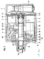
- Fig. 1 is a cross-sectional view showing a variable displacement compressor in a full stroke condition according to an embodiment of the present invention;
- Fig. 2 is a cross-sectional view showing the variable displacement compressor in a no-stroke condition;
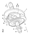
- Fig. 3 is a perspective view showing an assembly of a drive shaft, a rotor, and a swash plate of the variable displacement compressor in a full stroke condition;
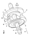
- Fig. 4 is a perspective view showing the assembly of the drive shaft, the rotor, and the swash plate of the variable displacement compressor in a no-stroke condition;
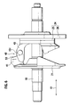
- Fig. 5 is a side view showing the assembly taken along the arrow V-V in Fig. 3;
- Fig. 6 is a side view showing the assembly taken along the arrow VI-VI in Fig. 4;
- Fig. 7 is a cross-sectional view showing a pin of a linkage mechanism in the variable displacement compressor;
- Fig. 8 is a perspective view showing the first modification of the first embodiment corresponding to Fig. 3;
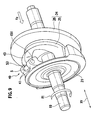
- Fig. 9 is a perspective view showing the second modification of the first embodiment corresponding to Fig. 3; and
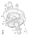
- Fig. 10 is a perspective view showing the third modification of the first embodiment corresponding to Fig. 3.
- A variable displacement compressor according to an embodiment of the present invention and a linkage mechanism used therein will be explained with reference to the drawings.
- Firstly, an over all structure of the variable displacement compressor will be explained with reference to Figs. 1 and 2. Fig. 1 shows a full stroke condition and Fig. 2 shows a destroke condition.
- As shown in Figs. 1 and 2, a variable displacement compressor 1 includes a
cylinder block 2, afront head 4 attached to a front end of thecylinder block 2, a rear head 6 attached to a rear end of thecylinder block 2 via a valve plate 9. Thecylinder block 2, thefront head 4, and the rear head 6 are fixed to each other by a plurality of penetrating bolts B and compose a housing of the compressor. - The
cylinder block 2 is formed in a substantially cylindrical shape and has a plurality ofcylinder bores 3 placed evenly spaced apart in a circumferential direction. Thefront head 2 is attached to the front end of thecylinder block 2 and has acrank chamber 5 therein. The rear head 6 is attached to the rear end of thecylinder block 2 via the valve plate 9 and has asuction chamber 7 and adischarge chamber 8 therein. - The valve plate 9 is formed with
suction ports 11 that communicates thecylinder bores 3 with thesuction chamber 7 and is formed withdischarge ports 12 that communicates thecylinder bores 3 with thedischarge chamber 8. - A valve system (not shown) adapted to open and close the
suction ports 11 is provided on the valve plate 9 at the cylinder block side. On the other hand, a valve system (not shown) adapted to open and close thedischarge ports 12 is provided on the valve plate 9 at the rear head side. A gasket is interposed between the valve plate 9 and the rear head 6 for providing an airtight sealing property between thesuction chamber 7 and thedischarge chamber 8. - A
drive shaft 10 is supported bybearings support holes cylinder block 2 and the front head 4so that thedrive shaft 10 is rotatable in thecrank chamber 5. - the
crank chamber 5 accommodates arotor 21 as a "rotating member" fixed to thedrive shaft 10, aswash plate 24 as a "tilting member" attached to the drive shaft slidably in the axial direction and tiltably with respect to the axis of the drive shaft, and alinkage mechanism 40 for linking therotor 21 and theswash plate 24. Thelinkage mechanism 40 links therotor 21 and theswash plate 24 so that therotor 21 and theswash plate 24 rotate integrally as allowing changes of the inclination angle of theswash plate 24. Theswash plate 24 includes ahub 25 attached to thedrive shaft 10 and aswash plate body 26 fixed to a boss segment 25a of thehub 25. To theswash plate body 26 of theswash plate 24, apiston 29 is linked via a pair of hemispherical-shaped shoes pistons 29 are slidably fit in each cylinder bore 3. - When the
drive shaft 10 rotates, therotor 21 rotates integrally with thedrive shaft 10, and theswash plate 24 rotates corresponding to therotor 21 via thelinkage mechanism 40. The rotation of theswash plate 24 is converted into a reciprocating movement of thepistons 29 by the pairs ofpiston shoes pistons 29 reciprocate in thecylinder bores 3. By the reciprocation of thepistons 29, refrigerant in thesuction chamber 7 is sucked into thecylinder bores 3 through thesuction ports 11 of the valve plate 9 to be compressed, and then discharged to thedischarge chamber 8 through thedischarge ports 12 of the valve plate 9. - In the variable displacement compressor, a pressure control mechanism is provided. The pressure control mechanism is configured to adjust a difference in pressure (pressure balance) between the crank chamber pressure Pc in back of the
pistons 29 and the suction chamber pressure Ps in front of thepistons 29 is provided in order to change the inclination angle of theswash plate 24. The pressure control mechanism includes a gas extraction passage (not shown) that allows thecrank chamber 5 to communicate with thesuction chamber 7, an gas supply passage (not shown) that allows thecrank chamber 5 to communicate with thedischarge chamber 8, and acontrol valve 33 that is provided in the midstream of the gas supply passage to open and close the gas supply passage. - When the
control valve 33 opens the gas supply passage, the refrigerant flows from thedischarge chamber 8 into thecrank chamber 5 through the gas supply passage, so that the crank chamber pressure Pc increases. With this, the pressure balance between the crank chamber pressure Pc and the suction chamber pressure Ps decreases the inclination angle of theswash plate 24. As a result, piston strokes become smaller so as to decrease the discharging amount. On the other hand, when thecontrol valve 33 closes the gas supply passage, the refrigerant is gradually extracted from thecrank chamber 5 to thesuction chamber 7 through the gas extraction passage, so that the crank chamber pressure Pc reduces. With this, the pressure balance between the crank chamber pressure Pc and the suction chamber pressure Ps increases the inclination angle of theswash plate 24. As a result, the piston strokes become longer so as to increase the discharging mount. In other words, the inclination angle of theswash plate 24 reduces when thehub 25 moves toward thecylinder block 2 and the inclination angle of theswash plate 24 increases when thehub 25 moves away from thecylinder block 2. - A
linkage mechanism 40 will be explained with reference to Figs. 3 to 7. - As shown in Figs. 3 to 6, the
linkage mechanism 40 includes anarm 41 extending from therotor 21 toward thehub 25 and anarm 43 extending from thehub 25 toward therotor 21. Thearm 41 of the rotor and thearm 43 of the hub are overlapped in the rotary torque transfer direction Ft (that is, the rotating direction of the drive shaft 10). With this structure, the rotary torque of therotor 21 is transferred to theswash plate 24. In this example, as shown in Figs. 3 and 4, thearm 43 is formed in a bifurcated shape having a slit S extending in the axial direction XY (orthogonally to the rotary torque transfer direction Ft) and thearm 41 is slidably fit in the slit S in a sandwiched manner. - When the
swash plate 24 rotates, thepistons 29 reciprocate so that compression reaction force (axial direction load Fp) from the pistons is applied to theswash plate 24. Thearm 43 of theswash plate 24 is formed with press-insertion holes 43s (see Fig. 7) that apin 151 is pressed into and fixed in. An axial directionload receiving face 53 is formed on an end of thearm 41 of therotor 21. The compression reaction force Fp is received at a contact between thepin 151 and the an axial directionload receiving face 53. - The
pin 151 extends in a tangential direction of rotary orbits of the rotatingmember 21 and theswash plate 24, in other words, extends toward the rotary torque transfer direction Ft. Since a large compression reaction force (axial direction load Fp) is applied to the contact between thepin 151 and the axial directionpressure receiving face 53 of therotor 21, the hardness of thepin 151 and the axial directionpressure receiving face 53 of therotor 21 is enhanced by a quenching process or the like. - With the above described structure, the present embodiment brings about the following effects.
- Firstly, according to the present embodiment, the
linkage mechanism 40 includes anarm 41 extending from arotor 21, anarm 43 extending from aswash plate 24 and receiving rotary torque from thearm 41 of the rotor, apin 151 fixed to one of thearm 41 of the rotor and thearm 43 of the swash plate (thearm 43 of the swash plate, in this embodiment), and an axial directionload receiving face 53 formed on the other of thearm 41 of the rotor and thearm 43 of the swash plate (thearm 41 of the rotor, in this embodiment) and configured to contact with thepin 151 to receive compression reaction force Fp (axial direction load) from thepistons 29. - Accordingly, the inclination angle of the
swash plate 24 is changed in the condition that great axial direction load Fp (compression reaction force from the pistons) is applied between thepin 151 and the axial directionload receiving face 53. However, since thepin 151 is a member formed separately from the arm (thearm 43 of the swash plate, in this embodiment), only thepin 151 can be quenched, etc. in a hardness enhancement process so that the arm (thearm 43 of the swash plate, in this embodiment) is not needed to be quenched. As a result, manufacturing cost can be reduced. - Further, since the
pin 151 is separated form the arm (thearm 43 of the swash plate, in this embodiment), it is relatively easy to form the outer surface of thepin 151 to be complicated. With such a case, the manufacturing cost can be reduced comparing to the case forming the arm (thearm 43 of the swash plate, in this embodiment) to be a complicated shape. - Further, only the
pin 151 can be exchanged. - Secondly, the linkage mechanism has a structure in which one of the
arms 41, 43 (thearm 43 of the swash plate, in this embodiment) is formed in a bifurcated shape having a slit S and the other of the arms (thearm 41 of the rotor, in this embodiment) is slidably fit in the slit S in a sandwiched manner. This structure is preferable since backlash is hardly provided between the botharms - As described above, according to the present invention, the linkage mechanism includes the arm extending form the rotating member, the arm extending from the tilting member and overlapped with the arm of the rotating member, the pin fixed to one of the arm of the rotating member and the arm of the tilting member, the axial direction load receiving face formed on the other of the arm of the rotating member and the arm of the tilting member arm and configured to contact with the pin to receive axial direction load between the rotating member and the tilting member. In this structure, the inclination angle of the tilting member is changed in a state that great axial direction load (compression reaction force from the pistons) is applied between the pin and the axial direction load receiving face. However, since the pin and the arm are individual members, only the pin can be quenched, etc. in a hardness enhancement process and the arm is not required to be quenched. As a result, the manufacturing cost can be reduced.
- It is noted that the present invention should not be limited to the above described embodiment.
- For example, according to the above embodiment, the pin 51 is fixed to the
arm 43 of the swash plate and the axial directionload receiving face 53 is formed on thearm 41 of the rotor. However, in the present invention, as shown in the first modification in Fig. 8 and the second modification in Fig. 9, the axial directionload receiving face 53 may be formed on thearm 43 of the swash plate and thepin 151 may be fixed to thearm 41 of the rotor. - According to the above embodiment, a slit S is provided to the
arm 43 of the swash plate and thearm 41 of the rotor is slidably held in the slit S. However, in the present invention, as shown in the second modification in Fig. 9 and the third modification in Fig. 10, the slit S may be provided to thearm 41 of the rotor and thearm 43 of the swash plate may be slidably fit in the slit S. - According to the above embodiment, the cross-section of the pin is a circular shape; however, in the present invention, it may be formed in other shapes.
- Further, according to the above embodiment, the
swash plate 24 is made in combination of theswash plate body 26 and thehub 25 which are separately formed; however, in the present invention, the swash plate body and the hub may be formed integrally in advance to constitute the swash plate. Further, the above embodiment employs a sleeveless structure in which theswash plate 24 is directly attached to thedrive shaft 10 without any sleeve; however, in the present invention, the swash plate may be attached to the drive shaft via a sleeve. - The present invention may be applied to not only a swash plate type variable displacement compressor but also a wobble plate type variable displacement compressor and the present invention may be implemented with various modifications.
Claims (3)
- A variable displacement compressor, comprising:a drive shaft;a rotating member fixed to the drive shaft and rotating integrally with the drive shaft;a tilting member attached to the drive shaft and being changeable a tilt thereof with respect to an axis of the drive shaft;a linkage mechanism configured to rotate the rotating member and the tilting member integrally with allowing the tilt of the tilting member to change; anda piston reciprocating in a cylinder bore corresponding to rotary movement of the tilting member; whereinthe linkage mechanism includes:an arm extending from the rotating member;an arm extending from the tilting member and overlapping with the arm of the rotating member in a rotating direction;a pin fixed to one of the arm of the rotating member and the arm of the tilting member; andan axial direction load receiving face formed on the other of the arm of the rotating member and the arm of the tilting member and configured to contact with the pin to receive an axial direction load applied between the rotating member and the tilting member.
- The variable displacement compressor according to claim 1, wherein the arm of the rotating member is formed in a bifurcated shape divided by a slit to slidably hold the arm of the tilting member in a sandwiching manner.
- The variable displacement compressor according to claim 1, wherein the arm of the tilting member is formed in a bifurcated shape divided by a slit to slidably hold the arm of the rotating member in a sandwiching manner.
Applications Claiming Priority (2)
| Application Number | Priority Date | Filing Date | Title |
|---|---|---|---|
| JP2005066123 | 2005-03-09 | ||
| PCT/JP2006/303044 WO2006095565A1 (en) | 2005-03-09 | 2006-02-21 | Variable displacement compressor |
Publications (1)
| Publication Number | Publication Date |
|---|---|
| EP1857675A1 true EP1857675A1 (en) | 2007-11-21 |
Family
ID=36953166
Family Applications (1)
| Application Number | Title | Priority Date | Filing Date |
|---|---|---|---|
| EP06714184A Withdrawn EP1857675A1 (en) | 2005-03-09 | 2006-02-21 | Variable displacement compressor |
Country Status (3)
| Country | Link |
|---|---|
| EP (1) | EP1857675A1 (en) |
| JP (1) | JPWO2006095565A1 (en) |
| WO (1) | WO2006095565A1 (en) |
Family Cites Families (4)
| Publication number | Priority date | Publication date | Assignee | Title |
|---|---|---|---|---|
| JP3422186B2 (en) * | 1995-11-24 | 2003-06-30 | 株式会社豊田自動織機 | Variable capacity compressor |
| JPH11336657A (en) * | 1998-05-27 | 1999-12-07 | Nippon Soken Inc | Swash plate type variable capacity compressor |
| JP4368055B2 (en) * | 2000-12-08 | 2009-11-18 | サンデン株式会社 | Connecting structure of rotor and swash plate of variable capacity swash plate compressor |
| JP2001304103A (en) * | 2001-03-30 | 2001-10-31 | Zexel Valeo Climate Control Corp | Variable displacement compressor |
-
2006
- 2006-02-21 JP JP2007507031A patent/JPWO2006095565A1/en active Pending
- 2006-02-21 WO PCT/JP2006/303044 patent/WO2006095565A1/en not_active Ceased
- 2006-02-21 EP EP06714184A patent/EP1857675A1/en not_active Withdrawn
Non-Patent Citations (1)
| Title |
|---|
| See references of WO2006095565A1 * |
Also Published As
| Publication number | Publication date |
|---|---|
| JPWO2006095565A1 (en) | 2008-08-14 |
| WO2006095565A1 (en) | 2006-09-14 |
Similar Documents
| Publication | Publication Date | Title |
|---|---|---|
| JP3047842B2 (en) | Processing method of piston for compressor | |
| KR100318772B1 (en) | Variable capacity swash plate type compressor | |
| US6524079B1 (en) | Alignment means for the swash plate of a variable-capacity swash-plate type compressor | |
| US6629823B2 (en) | Compressors | |
| EP2045465A1 (en) | Compressor | |
| EP2574786B1 (en) | Compressor | |
| EP0881386B2 (en) | Swash plate compressor | |
| US20070220859A1 (en) | Link Mechanism and Variable Displacement Compressor | |
| EP2063121A1 (en) | Variable displacement compressor | |
| US7972118B2 (en) | Variable capacity compressor | |
| EP1146228A2 (en) | Variable displacement compressors | |
| US20030025276A1 (en) | Shaft sealing devices, compressors comprising the shaft sealing devices, and methods for sealing a rotational shaft | |
| US20080302236A1 (en) | Variable Displacement Compressor | |
| WO2024018829A1 (en) | Compressor | |
| JP2001295755A (en) | Guide pin of variable capacity compressor and variable capacity compressor | |
| JP7073587B2 (en) | Slope type compressor | |
| EP1783369A1 (en) | Compressor | |
| KR100614023B1 (en) | Variable displacement compressor | |
| EP3292305B1 (en) | Method and system for enhancing performance of a reciprocating compressor | |
| JP4451323B2 (en) | Link mechanism and variable capacity compressor using the same | |
| JP4630801B2 (en) | Compressor | |
| JP4778773B2 (en) | Variable capacity compressor | |
| KR200347391Y1 (en) | A structure of thrust bearing in swash plate type compressor | |
| JP4128656B2 (en) | Swash plate compressor | |
| JPWO2006095565A1 (en) | Variable capacity compressor |
Legal Events
| Date | Code | Title | Description |
|---|---|---|---|
| PUAI | Public reference made under article 153(3) epc to a published international application that has entered the european phase |
Free format text: ORIGINAL CODE: 0009012 |
|
| 17P | Request for examination filed |
Effective date: 20061115 |
|
| AK | Designated contracting states |
Kind code of ref document: A1 Designated state(s): DE FR GB |
|
| DAX | Request for extension of the european patent (deleted) | ||
| RBV | Designated contracting states (corrected) |
Designated state(s): DE FR GB |
|
| STAA | Information on the status of an ep patent application or granted ep patent |
Free format text: STATUS: THE APPLICATION HAS BEEN WITHDRAWN |
|
| 18W | Application withdrawn |
Effective date: 20100921 |