EP1857277A1 - Sheet-fed printing press and printing method - Google Patents
Sheet-fed printing press and printing method Download PDFInfo
- Publication number
- EP1857277A1 EP1857277A1 EP06714552A EP06714552A EP1857277A1 EP 1857277 A1 EP1857277 A1 EP 1857277A1 EP 06714552 A EP06714552 A EP 06714552A EP 06714552 A EP06714552 A EP 06714552A EP 1857277 A1 EP1857277 A1 EP 1857277A1
- Authority
- EP
- European Patent Office
- Prior art keywords
- printing
- sheet
- dust
- printing press
- fed
- Prior art date
- Legal status (The legal status is an assumption and is not a legal conclusion. Google has not performed a legal analysis and makes no representation as to the accuracy of the status listed.)
- Withdrawn
Links
- 238000007639 printing Methods 0.000 title claims abstract description 186
- 238000000034 method Methods 0.000 title claims description 10
- 239000000428 dust Substances 0.000 claims abstract description 16
- 239000000843 powder Substances 0.000 claims description 36
- 238000007790 scraping Methods 0.000 claims description 7
- 239000004744 fabric Substances 0.000 claims description 5
- 230000001747 exhibiting effect Effects 0.000 abstract 1
- 229940098458 powder spray Drugs 0.000 abstract 1
- 239000000463 material Substances 0.000 description 29
- 239000011248 coating agent Substances 0.000 description 25
- 238000000576 coating method Methods 0.000 description 25
- 239000002245 particle Substances 0.000 description 24
- 239000000243 solution Substances 0.000 description 22
- 239000010410 layer Substances 0.000 description 20
- 239000004745 nonwoven fabric Substances 0.000 description 15
- 239000007787 solid Substances 0.000 description 14
- VYPSYNLAJGMNEJ-UHFFFAOYSA-N Silicium dioxide Chemical compound O=[Si]=O VYPSYNLAJGMNEJ-UHFFFAOYSA-N 0.000 description 13
- PPBRXRYQALVLMV-UHFFFAOYSA-N Styrene Chemical compound C=CC1=CC=CC=C1 PPBRXRYQALVLMV-UHFFFAOYSA-N 0.000 description 12
- 238000010586 diagram Methods 0.000 description 11
- 239000000126 substance Substances 0.000 description 11
- 238000007689 inspection Methods 0.000 description 9
- XLYOFNOQVPJJNP-UHFFFAOYSA-N water Substances O XLYOFNOQVPJJNP-UHFFFAOYSA-N 0.000 description 9
- 239000000203 mixture Substances 0.000 description 8
- 229910044991 metal oxide Inorganic materials 0.000 description 6
- 150000004706 metal oxides Chemical class 0.000 description 6
- 238000002360 preparation method Methods 0.000 description 6
- 239000000758 substrate Substances 0.000 description 6
- 239000007864 aqueous solution Substances 0.000 description 5
- CQEYYJKEWSMYFG-UHFFFAOYSA-N butyl acrylate Chemical compound CCCCOC(=O)C=C CQEYYJKEWSMYFG-UHFFFAOYSA-N 0.000 description 5
- VOZRXNHHFUQHIL-UHFFFAOYSA-N glycidyl methacrylate Chemical compound CC(=C)C(=O)OCC1CO1 VOZRXNHHFUQHIL-UHFFFAOYSA-N 0.000 description 5
- 239000004816 latex Substances 0.000 description 5
- 229920000126 latex Polymers 0.000 description 5
- 239000000377 silicon dioxide Substances 0.000 description 5
- 150000001450 anions Chemical class 0.000 description 4
- 238000007664 blowing Methods 0.000 description 4
- 239000003153 chemical reaction reagent Substances 0.000 description 4
- 238000005516 engineering process Methods 0.000 description 4
- 239000003317 industrial substance Substances 0.000 description 4
- 229910052500 inorganic mineral Inorganic materials 0.000 description 4
- 239000006224 matting agent Substances 0.000 description 4
- 239000011707 mineral Substances 0.000 description 4
- 239000004094 surface-active agent Substances 0.000 description 4
- LYCAIKOWRPUZTN-UHFFFAOYSA-N Ethylene glycol Chemical compound OCCO LYCAIKOWRPUZTN-UHFFFAOYSA-N 0.000 description 3
- BPQQTUXANYXVAA-UHFFFAOYSA-N Orthosilicate Chemical compound [O-][Si]([O-])([O-])[O-] BPQQTUXANYXVAA-UHFFFAOYSA-N 0.000 description 3
- 239000003513 alkali Substances 0.000 description 3
- 239000008119 colloidal silica Substances 0.000 description 3
- 238000003851 corona treatment Methods 0.000 description 3
- 238000002844 melting Methods 0.000 description 3
- 230000008018 melting Effects 0.000 description 3
- 238000005507 spraying Methods 0.000 description 3
- 229920001897 terpolymer Polymers 0.000 description 3
- QPFMBZIOSGYJDE-UHFFFAOYSA-N 1,1,2,2-tetrachloroethane Chemical compound ClC(Cl)C(Cl)Cl QPFMBZIOSGYJDE-UHFFFAOYSA-N 0.000 description 2
- 229910002551 Fe-Mn Inorganic materials 0.000 description 2
- RRHGJUQNOFWUDK-UHFFFAOYSA-N Isoprene Chemical compound CC(=C)C=C RRHGJUQNOFWUDK-UHFFFAOYSA-N 0.000 description 2
- 239000004640 Melamine resin Substances 0.000 description 2
- 229920000877 Melamine resin Polymers 0.000 description 2
- 239000004677 Nylon Substances 0.000 description 2
- 239000004698 Polyethylene Substances 0.000 description 2
- KKEYFWRCBNTPAC-UHFFFAOYSA-N Terephthalic acid Chemical compound OC(=O)C1=CC=C(C(O)=O)C=C1 KKEYFWRCBNTPAC-UHFFFAOYSA-N 0.000 description 2
- 239000003795 chemical substances by application Substances 0.000 description 2
- 239000004927 clay Substances 0.000 description 2
- 239000000084 colloidal system Substances 0.000 description 2
- 230000000052 comparative effect Effects 0.000 description 2
- GUJOJGAPFQRJSV-UHFFFAOYSA-N dialuminum;dioxosilane;oxygen(2-);hydrate Chemical compound O.[O-2].[O-2].[O-2].[Al+3].[Al+3].O=[Si]=O.O=[Si]=O.O=[Si]=O.O=[Si]=O GUJOJGAPFQRJSV-UHFFFAOYSA-N 0.000 description 2
- 239000002270 dispersing agent Substances 0.000 description 2
- 238000011156 evaluation Methods 0.000 description 2
- 238000010438 heat treatment Methods 0.000 description 2
- 229910052901 montmorillonite Inorganic materials 0.000 description 2
- 229920001778 nylon Polymers 0.000 description 2
- 239000000049 pigment Substances 0.000 description 2
- 239000004033 plastic Substances 0.000 description 2
- 229920003023 plastic Polymers 0.000 description 2
- -1 polyethylene Polymers 0.000 description 2
- 229920000573 polyethylene Polymers 0.000 description 2
- 239000004065 semiconductor Substances 0.000 description 2
- 239000001488 sodium phosphate Substances 0.000 description 2
- 239000002344 surface layer Substances 0.000 description 2
- RYFMWSXOAZQYPI-UHFFFAOYSA-K trisodium phosphate Chemical compound [Na+].[Na+].[Na+].[O-]P([O-])([O-])=O RYFMWSXOAZQYPI-UHFFFAOYSA-K 0.000 description 2
- 229910000406 trisodium phosphate Inorganic materials 0.000 description 2
- 235000019801 trisodium phosphate Nutrition 0.000 description 2
- IBDVWXAVKPRHCU-UHFFFAOYSA-N 2-(2-methylprop-2-enoyloxy)ethyl 3-oxobutanoate Chemical compound CC(=O)CC(=O)OCCOC(=O)C(C)=C IBDVWXAVKPRHCU-UHFFFAOYSA-N 0.000 description 1
- 235000013162 Cocos nucifera Nutrition 0.000 description 1
- 244000060011 Cocos nucifera Species 0.000 description 1
- 229920001875 Ebonite Polymers 0.000 description 1
- 239000001828 Gelatine Substances 0.000 description 1
- DGAQECJNVWCQMB-PUAWFVPOSA-M Ilexoside XXIX Chemical compound C[C@@H]1CC[C@@]2(CC[C@@]3(C(=CC[C@H]4[C@]3(CC[C@@H]5[C@@]4(CC[C@@H](C5(C)C)OS(=O)(=O)[O-])C)C)[C@@H]2[C@]1(C)O)C)C(=O)O[C@H]6[C@@H]([C@H]([C@@H]([C@H](O6)CO)O)O)O.[Na+] DGAQECJNVWCQMB-PUAWFVPOSA-M 0.000 description 1
- 208000035155 Mitochondrial DNA-associated Leigh syndrome Diseases 0.000 description 1
- ISWSIDIOOBJBQZ-UHFFFAOYSA-N Phenol Chemical compound OC1=CC=CC=C1 ISWSIDIOOBJBQZ-UHFFFAOYSA-N 0.000 description 1
- OFOBLEOULBTSOW-UHFFFAOYSA-N Propanedioic acid Natural products OC(=O)CC(O)=O OFOBLEOULBTSOW-UHFFFAOYSA-N 0.000 description 1
- DPXJVFZANSGRMM-UHFFFAOYSA-N acetic acid;2,3,4,5,6-pentahydroxyhexanal;sodium Chemical compound [Na].CC(O)=O.OCC(O)C(O)C(O)C(O)C=O DPXJVFZANSGRMM-UHFFFAOYSA-N 0.000 description 1
- 239000012190 activator Substances 0.000 description 1
- IDZYHGDLWGVHQM-UHFFFAOYSA-N aluminum;calcium;sodium;silicate Chemical compound [Na+].[Al+3].[Ca+2].[O-][Si]([O-])([O-])[O-] IDZYHGDLWGVHQM-UHFFFAOYSA-N 0.000 description 1
- 125000000129 anionic group Chemical group 0.000 description 1
- 150000001718 carbodiimides Chemical class 0.000 description 1
- 239000001768 carboxy methyl cellulose Substances 0.000 description 1
- 239000004203 carnauba wax Substances 0.000 description 1
- 235000013869 carnauba wax Nutrition 0.000 description 1
- 238000004140 cleaning Methods 0.000 description 1
- 239000002131 composite material Substances 0.000 description 1
- 150000001875 compounds Chemical class 0.000 description 1
- 229920001577 copolymer Polymers 0.000 description 1
- 238000007334 copolymerization reaction Methods 0.000 description 1
- 239000003431 cross linking reagent Substances 0.000 description 1
- 230000007423 decrease Effects 0.000 description 1
- 239000006185 dispersion Substances 0.000 description 1
- 239000003814 drug Substances 0.000 description 1
- 229940079593 drug Drugs 0.000 description 1
- 238000001035 drying Methods 0.000 description 1
- 230000000694 effects Effects 0.000 description 1
- 239000000839 emulsion Substances 0.000 description 1
- 239000000835 fiber Substances 0.000 description 1
- 235000011194 food seasoning agent Nutrition 0.000 description 1
- 230000000855 fungicidal effect Effects 0.000 description 1
- 239000000417 fungicide Substances 0.000 description 1
- 229920000159 gelatin Polymers 0.000 description 1
- 235000019322 gelatine Nutrition 0.000 description 1
- 238000003384 imaging method Methods 0.000 description 1
- 230000001788 irregular Effects 0.000 description 1
- 239000007788 liquid Substances 0.000 description 1
- VZCYOOQTPOCHFL-UPHRSURJSA-N maleic acid Chemical compound OC(=O)\C=C/C(O)=O VZCYOOQTPOCHFL-UPHRSURJSA-N 0.000 description 1
- 239000011976 maleic acid Substances 0.000 description 1
- 208000003531 maternally-inherited Leigh syndrome Diseases 0.000 description 1
- 238000005259 measurement Methods 0.000 description 1
- 238000007645 offset printing Methods 0.000 description 1
- 229920001495 poly(sodium acrylate) polymer Polymers 0.000 description 1
- 230000001737 promoting effect Effects 0.000 description 1
- 229920006296 quaterpolymer Polymers 0.000 description 1
- 229920005989 resin Polymers 0.000 description 1
- 239000011347 resin Substances 0.000 description 1
- 230000000630 rising effect Effects 0.000 description 1
- 238000000926 separation method Methods 0.000 description 1
- 230000035939 shock Effects 0.000 description 1
- 229910052708 sodium Inorganic materials 0.000 description 1
- 239000011734 sodium Substances 0.000 description 1
- 235000019812 sodium carboxymethyl cellulose Nutrition 0.000 description 1
- 229920001027 sodium carboxymethylcellulose Polymers 0.000 description 1
- MNCGMVDMOKPCSQ-UHFFFAOYSA-M sodium;2-phenylethenesulfonate Chemical compound [Na+].[O-]S(=O)(=O)C=CC1=CC=CC=C1 MNCGMVDMOKPCSQ-UHFFFAOYSA-M 0.000 description 1
- 239000012798 spherical particle Substances 0.000 description 1
- BDHFUVZGWQCTTF-UHFFFAOYSA-M sulfonate Chemical compound [O-]S(=O)=O BDHFUVZGWQCTTF-UHFFFAOYSA-M 0.000 description 1
- VZCYOOQTPOCHFL-UHFFFAOYSA-N trans-butenedioic acid Natural products OC(=O)C=CC(O)=O VZCYOOQTPOCHFL-UHFFFAOYSA-N 0.000 description 1
Images




Classifications
-
- B—PERFORMING OPERATIONS; TRANSPORTING
- B41—PRINTING; LINING MACHINES; TYPEWRITERS; STAMPS
- B41F—PRINTING MACHINES OR PRESSES
- B41F23/00—Devices for treating the surfaces of sheets, webs, or other articles in connection with printing
- B41F23/002—Devices for treating the surfaces of sheets, webs, or other articles in connection with printing cleaning devices for sheets or webs
-
- B—PERFORMING OPERATIONS; TRANSPORTING
- B41—PRINTING; LINING MACHINES; TYPEWRITERS; STAMPS
- B41F—PRINTING MACHINES OR PRESSES
- B41F23/00—Devices for treating the surfaces of sheets, webs, or other articles in connection with printing
- B41F23/04—Devices for treating the surfaces of sheets, webs, or other articles in connection with printing by heat drying, by cooling, by applying powders
- B41F23/06—Powdering devices, e.g. for preventing set-off
Definitions
- the present invention relates to a sheet-fed printing press, and in particular, to a printing press that prints by using blocking-prevention powder, specifically, to a sheet-fed printing press suitable for using a printing plate of a computer-to-plate (CTP) mode for printing.
- CTP computer-to-plate
- Patent Document 1 a technology of separation and collection of powder to be used for offset printing
- Patent Document 2 a technology for promoting sticking of powder by spraying water on offsetting-prevention powder on printing paper and thereby for reducing an amount of powder used
- Patent Document 3 a technology for preventing scattering of blocking-prevention powder by providing a dust collecting device on a sheet ejecting section of a sheet-fed printing press
- Patent Documents 3 and 4 a powder removing and collecting method at an exit of the sheet ejecting section is still insufficient, and workability and plate life are inferior to those of the conventional printing plate, which has been a problem.
- Patent Document 1 Japanese Patent Publication Open to Public Inspection No. 7-17022
- Patent Document 2 Japanese Patent Publication Open to Public Inspection No. 8-52858
- Patent Document 3 Japanese Patent Publication Open to Public Inspection No. 8-295007
- Patent Document 4 Japanese Patent Publication Open to Public Inspection No. 2003-320642
- the present invention has been achieved to solve the aforesaid problems, and its objective is to provide a sheet-fed printing press wherein workability is excellent even in spraying of blocking-prevention powder in printing operations identical to those in the past, and a plate life of a printing plate is enhanced by the printing press body, whereby, a printing plate of any type can be used, a printing plate does not need to be replaced on the half way, and low cost is realized.
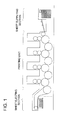
- Fig. 1 is a schematic diagram of a sheet-fed printing press used for a printing method of the invention, and sheet-fed printing press is composed of a sheet-feeding device, a printing unit and a sheet ejecting section.
- Fig. 2 and Fig. 3 represents a sheet-feeding device which is extracted from Fig. 1, and it is a schematic diagram of a printing device having a blocking-prevention powder (hereinafter referred to as "powder”) removing mechanism on a sheet-feeding device.
- powder blocking-prevention powder
- a means to remove dust by blowing compressed air, or a means to remove dust by scraping it off is preferable.
- Fig. 2 is an enlarged schematic diagram of a printing press having a compressed air jetting nozzle (hereinafter referred to as "jetting nozzle") 7 on the sheet-feeding device.
- the numeral 1 represents a printing unit and the numeral 13 represents a sheet-feeding unit.
- a feeder portion relating to the invention means a portion where feeder board 10 is in existence and a place from the feeder board to the printing unit.
- the jetting nozzles 7 are arranged to be longer than the total width of printing paper 15. As a distance from printing paper 15, it is preferable that a tip of the nozzle is away from printing paper 15 by 1 - 50 mm, and it is more preferable to be away by 5 - 30 mm. Owing to this, it is possible to remove foreign substances such as dust and powder sticking to printing paper 15 effectively.
- Fig. 3 is a schematic diagram of a printing press wherein a sheet-feeding device has thereon jetting nozzle 7 and suction nozzle 16 which are housed in casing 17 which is of a box structure.
- Printing paper 15 whose surface has been printed is lifted one by one by by sheet-feeding section separator 14 to be conveyed to a feeder board.
- powder sticking to the printing paper 15 is blown off by compressed air jetted from jetting nozzle 7.
- the powder thus blown off is sucked by suction nozzle 16 connected to suction device 18 representing a dust-collecting means so that scattering is prevented.
- the casing 17 plays a role to prevent scattering of powder to a circumference, and it enhances efficiency of blowing off and suction of powder.
- printing paper 15 is conveyed to printing unit 1 by swing gripper 6 to be printed on its reverse side.
- an orifice of the jetting nozzle 7 is turned to face sheet-feeding unit 13.
- a range of 5 - 85° is preferable when a surface to be printed of the printing paper 15 is 0°, and a range of 10 - 60° is more preferable, which is the same as the occasion in Fig. 2.
- the jetting nozzles 7 are arranged to be longer than the total width of printing paper 15.
- Suction nozzle 16 is arranged to face jetting nozzle 7, and as an angle for fixing, a range of 3 - 85° is preferable when a surface to be printed of the printing paper 15 is 0°, and a range of 5 - 60° is more preferable. Further, it is preferable that the suction nozzle is arranged to have the same angle and the same length as in the case of the jetting nozzle 7. Further, the jetting nozzles 7 are arranged to be longer than the total width of printing paper 15.
- a tip of the nozzle is away from printing paper 15 by 1 - 50 mm, and it is more preferable to be away by 5 - 30 mm, which is the same as the occasion in Fig. 2. Owing to this, it is possible to remove powder sticking to printing paper 15 effectively without scattering.
- timing for blowing compressed air it is also possible to blow the compressed air on a pulse pattern basis at the timing for swing gripper 6 to catch the printing paper 15, although it is possible to blow continuously during printing.
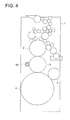
- FIG. 4, 5 and 6 is an enlarged schematic diagram of a printing press having a powder-removing mechanism on each printing unit 1.
- the numeral 2 represents a printing cylinder on which a printing plate is stuck
- 3 represents a blanket cylinder
- 4 represents an impression cylinder
- 5 represents an intermediate cylinder.
- printing paper 15 whose surface has been printed is lifted one by one by sheet-feeding section separator 14, and passes through feeder board 10 and intermediate cylinder 5 to pass through the space between blanket cylinder 3 and impression cylinder 4.
- ink is given from the blanket cylinder and transferring is carried out firmly at impression cylinder 4. Simultaneously with this, powder sticking on printing paper 15 is transferred onto the blanket cylinder 3.
- the powder thus transferred is removed from the blanket cylinder by the use of rotary brush 50.
- Bristles used as materials for the rotary brush include nylon, hog bristles, coconut fibers and others which can be used without any restriction, and nylon among them is preferable.
- the brush is brought into contact with the blanket cylinder 3 simultaneously with a start of printing. Further, it is preferable that the brush is rotated in the direction opposite to that of the blanket cylinder 3.
- the powder thus transferred is removed from the blanket cylinder by the use of nonwoven fabric 60.
- nonwoven fabric As a condition in the case of the nonwoven fabric, it is preferable to use nonwoven fabric that is long and is in a roll shape.
- the nonwoven fabric can either be brought into contact continuously or be brought into contact intermittently.
- nonwoven fabric 60 is rewound gradually so that a fresh portion of the nonwoven fabric may be used constantly for removing of powder.
- a rewinding speed in that case for the nonwoven fabric 0.5 - 100 cm/min. is preferable, and 1 - 50 cm/min. is more preferable.
- the powder transferred is removed from the blanket cylinder by the use of blade 70.
- blade 70 As materials for blade 70, SUS, plastics, hard rubber and others can be used without any restriction, and plastics among them are preferable.
- the blade 70 is brought into contact with the blanket cylinder 3 simultaneously with a start of printing.
- the side for removing powder is inclined as shown in Fig. 6.
- the blade 70 As an angle for the blade 70 to be in contact with blanket cylinder 3, it is preferable that the blade 70 is in parallel with a tangent line passing through an optional one point on the surface of the blanket, and an inclined surface of the blade is in a range of 30 - 150° when a certain direction of impression cylinder 4 is 0°.
- the scraping means is any one of the aforesaid rotary brush, unwoven fabric and blade.
- a 4-color printing press for example, when printing units are mounted in the order of the first printing unit, the second printing unit the third printing unit and the fourth printing unit from the sheet-feeding device, it is important to mount beginning with the printing unit on the sheet-feeding device side, when the number of dust-removing devices is less than the number of printing units, although the dust-removing device may be represented by any one of the first - fourth printing units. In particular, mounting on the first printing unit is indispensable. This also applies equally to an offset sheet-fed printing press other than the 4-color printing press.
- Processless printing plates capable of being used in the invention include those which are heretofore known. For example, they are represented by a type that is phase-converted from hydrophilic nature to lipophilic nature through light exposure such as those disclosed in Japanese Patent Publication Open to Public Inspection Nos. 7-1849 , 7-1850 , 9-311443 , 10-6468 , 10-114168 and 2000-118160 , a type that has an image forming layer having therein thermal melting grains as main components on a hydrophilic support and is processed on a printing press such as those disclosed in Japanese Patent Publication Open to Public Inspection Nos.
- infrared laser More specifically, concerning light exposure, scanning exposure using lasers emitting light in infrared and/or near-infrared area, namely, emitting light in wavelength range of 700 - 1500 nm is preferable.
- lasers though gas lasers may be used, it is especially preferable to use a semiconductor laser emitting light in near-infrared area.
- a device suitable for scanning exposure may be a device of any type provided that the device can form images, by using a semiconductor laser, on the surface of a printing plate material based on image signals coming from a computer.
- the device suitable for scanning exposure there are given generally the following three systems as the device suitable for scanning exposure.
- a system to give exposure to the whole surface of a printing plate material by scanning the printing plate material held on a cylindrical surface inside a fixed cylindrical holding mechanism in the circumferential direction of a cylinder (main scanning direction) from the inside of the cylinder by the use of a single or plural laser beams, and by moving the printing plate material in the direction perpendicular to the circumferential direction (sub-scanning direction).
- a system to give exposure to the whole surface of a printing plate material by scanning the printing plate material held on a cylindrical drum surface rotating around a shaft representing a rotating body, in the circumferential direction (main scanning direction) through rotation of the drum from the outside of the cylinder by the use of a single or plural laser beams, and by moving the printing plate material in the direction perpendicular to the circumferential direction (sub-scanning direction).
- the scanning exposure system of the aforesaid item (3) is preferable, and an exposure system of the item (3) is used especially for a device wherein an exposure operation is carried out on a printing press.
- the printing plate material described in Japanese Patent Publication Open to Public Inspection No. 2005-14409 was prepared in the following procedures.
- PET polyethylene telephthalate
- IV inherent viscosity
- mass ratio mass ratio
- Both sides of the substrate thus obtained were subjected to corona discharge treatment at 8W/m 2 ⁇ min., and then, coating solution for subbing a with the following composition was coated on the surface on one side in a way to obtain a thickness of dried coating of 0.8 ⁇ m, then, coating solution for subbing b was coated in a way to obtain a thickness of dried coating of 0.1 ⁇ m, while conducting corona discharge treatment (8W/m 2 ⁇ min.), and each of the coating solutions was dried at 180°C for 4 minutes (subbing surface A).
- coating solution for subbing c with the following composition was coated on the opposite surface in a way to obtain a thickness of dried coating of 0.8 ⁇ m, then, coating solution for subbing d was coated in a way to obtain a thickness of dried coating of 1.0 ⁇ m, while conducting corona discharge treatment (8W/m 2 ⁇ min.), and each of the coating solutions was dried at 180°C for 4 minutes (subbing surface B).
- Gelatine 1.0% Anion-based surfactant S-1 0.05% Hardening agent H-1 0.02% Matting agent (Silica, average particle size 3.5 ⁇ m) 0.02% Fungicide F-1 0.01% Water 98.9%
- Conductive composite having component d-11 / component d-12 / component d-13 66/31/1 6.4 parts Anion-based surfactant S-1 0.07 parts Hardening agent H-2 0.7 parts Matting agent (Silica, average particle size 3.5 ⁇ m) 0.03 parts Water 93.4 parts
- a coating solution for hydrophilic layer 1 shown in Table 1, a coating solution for hydrophilic layer 2 shown in Table 2 and a coating solution for the image forming layer shown in Table 3 were coated on subbing surface A of the aforesaid subbed substrate, by the use of a wire bar.
- the wire bar was used first in the order of the first hydrophilic layer 1 and the second hydrophilic layer 2 to coat on the substrate in a way to obtain respectively dry weight of 2.5 g/m 2 and 0.6 g/m 2 , and the hydrophilic layers were subjected to heat treatment at 60°C for 24 hours after being dried at 120°C for 3 minutes.
- Respective materials described in Table 1 were sufficiently stirred and mixed by a homogenizer, and then were mixed and filtered at compositions described in Table 1, to prepare a coating solution for hydrophilic layer 1. Numerical values showing mixture ratios of respective materials in the Table are parts by weight.
- colloidal silica (alkali-based): Snowtex-XS (made by NISSAN CHEMICAL INDUSTRIES, LTD., solid content 20% by weight) 68 STN-6500S made by NISSAN CHEMICAL INDUSTRIES, LTD., (Average particle size 6.5 ⁇ m, A core is made of melamine resin, and a shell is made of silica) 2 Cu-Fe-Mn-based metal oxide black pigment: Water-dispersed-substance with solid content 40% by weight (0.2% by weight of which is dispersant) of TM-3550 black dust (made by Dainichiseika Color & Chemicals Mfg. Co., Ltd., particle size, approx.
- Respective materials described in Table 2 were sufficiently stirred and mixed by a homogenizer, and then were mixed and filtered at compositions described in Table 2, to prepare a coating solution for hydrophilic layer 1. Numerical values showing mixture ratios of respective materials in the Table are parts by weight.
- Colloidal silica (alkali-based): Snowtex-S (made by NISSAN CHEMICAL INDUSTRIES, LTD., solid content 30% by weight) 17.3 Necklace-shaped colloidal silica (alkali-based): Snowtex-PSM (made by NISSAN CHEMICAL INDUSTRIES, solid content 20% by weight) 38.7 Matting agent STM-6500S (Irregular surface spherical particle with average particle size 6.5 ⁇ m wherein a core is made of melamine resin, and a shell is made of silica; made by NISSAN CHEMICAL INDUSTRIES) 3 Cu-Fe-Mn-based metal oxide black pigment: Water-dispersed-substance with solid content 40% by weight (0.2% by weight of which is dispersant) of TM-3550 black dust (made by Dainichis Color & Chemicals Mfg.
- Respective materials described in Table 3 were sufficiently stirred and mixed by a homogenizer, and then were mixed and filtered at compositions described in Table 3, to prepare a coating solution for an image forming layer.
- Numerical values showing mixture ratios of respective materials in the Table are parts by weight.
- Print operation Nos. 1 - 7 By using the printing plate thus obtained, printing was carried out (Printing operation Nos. 1 - 7) by installing an air type device on a sheet-fed printing press under the conditions shown in Table 4. In addition, printing was carried out (Printing operation Nos. 10 - 14) by installing on a sheet-fed printing press under the conditions shown in Table 5.
- Printing paper Mu coat (made by HOKUETSU PAPER MILS, LTD., 104.7 g/m 2 )
- Aqueous dampening solution ASTROMARK 3 (made by Nikken Kagaku Kenkyusho) 2% solution
- Toyo King HYECOO Magenta (made by TOYO INK MFG. CO. LTD.) was used for printing. After exposure, the printing plate material was installed as it is on the printing cylinder, and the same print-starting sequence as that in the presensitized plate was used for printing.
- Scraping device Mounting section Plate life 10 (Comparative Eample) None - 3,000 11 (present invention) Brush First printing unit 10,000 or more 12 (present invention) Unwoven fabric First printing unit 10,000 or more 13 (present invention) Unwoven fabric Total printing units 10,000 or more 14 (present invention) Blade First printing unit 10,000 or more
Landscapes
- Engineering & Computer Science (AREA)
- Mechanical Engineering (AREA)
- Printing Plates And Materials Therefor (AREA)
- Supply, Installation And Extraction Of Printed Sheets Or Plates (AREA)
Abstract
A sheet-fed printing press exhibiting excellent workability is provided, in which even by powder spray in print work equal to conventional one, any printing plate can be used because wear is enhanced by the printing press body and with which low cost can be realized by eliminating the need for changing the printing plate in the middle. A single-side printing sheet-fed printing press, including a print unit, and a sheet fed section having a feeder portion for feeding a sheet to the print unit, is characterized in that at least one of the feeder portion and the print unit has a dust removing means.
Description
- The present invention relates to a sheet-fed printing press, and in particular, to a printing press that prints by using blocking-prevention powder, specifically, to a sheet-fed printing press suitable for using a printing plate of a computer-to-plate (CTP) mode for printing.
- With the digitization of printing data, there is a demand for CTP that is inexpensive and easy to handle and has an aptitude for printing identical to that of a presensitized plate. In recent years, in particular, there are rising expectations for thermal-processessless printing plate that can be applied to a printing press that does not require photographic processing by specific drug and is equipped with direct imaging (DI) functions, and has the same utility as that of the presensitized plate.
- With respect to materials for a printing plate in recent years, a so-called processless printing plate requiring no photographic process has just started to be put to practical use. For example,
Japanese Patent Publication Open to Public Inspection Nos. 7-1849 7-164773 9-123387 10-193823 - Further, when viewed from the side of a machine, there has been a problem that a blanket cylinder tends to be soiled to lower printing quality easily, when printing by using blocking-prevention powder as in the past. It is therefore necessary to increase the number of times for cleaning that interrupts printing operations, which has been a problem of a decline of operation efficiency.
- For the purpose of improving the aforesaid points, there have been disclosed technologies including a technology of separation and collection of powder to be used for offset printing (see Patent Document 1), a technology for promoting sticking of powder by spraying water on offsetting-prevention powder on printing paper and thereby for reducing an amount of powder used (see Patent Document 2), and a technology for preventing scattering of blocking-prevention powder by providing a dust collecting device on a sheet ejecting section of a sheet-fed printing press (see, for example,
Patent Documents 3 and 4). However, a powder removing and collecting method at an exit of the sheet ejecting section is still insufficient, and workability and plate life are inferior to those of the conventional printing plate, which has been a problem. - Patent Document 1:
Japanese Patent Publication Open to Public Inspection No. 7-17022 - Patent Document 2:
Japanese Patent Publication Open to Public Inspection No. 8-52858 - Patent Document 3:
Japanese Patent Publication Open to Public Inspection No. 8-295007 - Patent Document 4:
Japanese Patent Publication Open to Public Inspection No. 2003-320642 - The present invention has been achieved to solve the aforesaid problems, and its objective is to provide a sheet-fed printing press wherein workability is excellent even in spraying of blocking-prevention powder in printing operations identical to those in the past, and a plate life of a printing plate is enhanced by the printing press body, whereby, a printing plate of any type can be used, a printing plate does not need to be replaced on the half way, and low cost is realized.
- The aforesaid objective of the invention has been achieved by the following structures.
-
Item 1. A single-sided sheet-fed printing press having therein a printing unit and a sheet-feeding device having a feeder portion that feeds a sheet to the printing unit, wherein at least one of the feeder portion and the printing unit has a dust-removing device. -
Item 2. The sheet-fed printing press described inItem 1 wherein the dust-removing means is a means to remove dust by blowing compressed air. -
Item 3. The sheet-fed printing press described inItem 1 wherein the dust-removing means is a means to remove dust by scraping. -
Item 4. The sheet-fed printing press described inItem 3 wherein the means to remove dust by scraping is at least one type selected from a brush, non-woven fabric and a blade.Item 5. The sheet-fed printing press described in at least one of Items 1 - 4 wherein a further dust collecting means is provided. - Item 6. The sheet-fed printing press described in
Item 5 wherein the aforesaid dust-removing means and the dust collecting means are provided in a casing which is totally of a box structure. - Item 7. A printing method conducting double-sided printing by using the sheet-fed printing press described in any one of Items 1 - 6, wherein dust is removed from the opposite side on the feeder portion and the aforesaid printing unit, when printing on the opposite side, after supplying blocking-prevention powder on the surface to be printed for the single-sided printing, after single-sided printing.
- In the sheet-fed printing press of the invention, workability is excellent even in spraying of powder in printing operations identical to those in the past, and a plate life of a printing plate is enhanced by the printing press main body, whereby, a printing plate of any type can be used, a printing plate does not need to be replaced on the half way, and low cost is realized.
-
- Fig. 1 is an overall schematic diagram of a sheet-fed printing press used for a printing method of the invention.
- Fig. 2 is an enlarged schematic diagram of a sheet-fed printing press having a compressed air jetting nozzle (for removing blocking-prevention powder) on a sheet-feeding device.
- Fig. 3 is an enlarged schematic diagram of a sheet-fed printing press having a compressed air jetting nozzle (for removing blocking-prevention powder) and a suction nozzle on a sheet-feeding device.
- Fig. 4 is an enlarged schematic diagram of a sheet-fed printing press having, on a printing unit, a blocking-prevention powder removing mechanism by a rotary brush.
- Fig. 5 is an enlarged schematic diagram of a sheet-fed printing press having, on a printing unit, a blocking-prevention powder removing mechanism by unwoven fabric.
- Fig. 6 is an enlarged schematic diagram of a sheet-fed printing press having, on a printing unit, a blocking-prevention powder removing mechanism by a blade.
-
- 1. Printing unit
- 2. Printing cylinder
- 3. Blanket cylinder
- 4. Impression cylinder
- 5. Intermediate cylinder
- 6. Swing gripper
- 7. Compressed air jetting nozzle
- 8. Sheet feed roll
- 9. Sheet feed belt
- 10. Feeder board
- 11. Sheet feed roller
- 12. Feeding roller
- 13. Sheet supply unit
- 14. Sheet supply section separator
- 15. Printing paper (whose one side has been printed)
- 16. Suction nozzle
- 17. Casing
- 18. Suction device
- 19. Compressor
- 50. Rotary brush
- 60. Non-woven fabric
- 61. Non-woven fabric roll
- 62. Pressure roll
- 63. Wind-up roll
- 70. Scraping blade
- 71. Catch pan
- An example of the embodiment relating to the invention will be explained as follows, referring to Fig. 1 - Fig. 6, to which, however, the invention is not limited.
- Fig. 1 is a schematic diagram of a sheet-fed printing press used for a printing method of the invention, and sheet-fed printing press is composed of a sheet-feeding device, a printing unit and a sheet ejecting section. Each of Fig. 2 and Fig. 3 represents a sheet-feeding device which is extracted from Fig. 1, and it is a schematic diagram of a printing device having a blocking-prevention powder (hereinafter referred to as "powder") removing mechanism on a sheet-feeding device.
- As a dust-removing means relating to the invention, a means to remove dust by blowing compressed air, or a means to remove dust by scraping it off is preferable.
- Fig. 2 is an enlarged schematic diagram of a printing press having a compressed air jetting nozzle (hereinafter referred to as "jetting nozzle") 7 on the sheet-feeding device. The
numeral 1 represents a printing unit and the numeral 13 represents a sheet-feeding unit. First, printing paper 15 (stacked with its reverse side facing upward) which has been printed on its surface is lifted one by one by sheet-feedingsection separator 14 to be conveyed tofeeder board 10. A feeder portion relating to the invention means a portion wherefeeder board 10 is in existence and a place from the feeder board to the printing unit. Between a period of time for printingpaper 15 to run through the feeder board to arrive at swing gripper 6, power sticking to the printing paper 15 (powder which has stuck in the case of printing on the surface) is blown off by compressed air jetting from jetting nozzle 7. After that, theprinting paper 15 is conveyed by the swing gripper 6 toprinting unit 1 to be printed on its reverse side, and is ejected. In that case, it is preferable that an orifice of the jetting nozzle 7 is turned to face sheet-feedingunit 13. As an angle for the orifice to be fixed, a range of 5 - 85° is preferable when a surface to be printed of theprinting paper 15 is 0°, and a range of 10 - 60° is more preferable. Further, the jetting nozzles 7 are arranged to be longer than the total width ofprinting paper 15. As a distance from printingpaper 15, it is preferable that a tip of the nozzle is away from printingpaper 15 by 1 - 50 mm, and it is more preferable to be away by 5 - 30 mm. Owing to this, it is possible to remove foreign substances such as dust and powder sticking to printingpaper 15 effectively. - Fig. 3 is a schematic diagram of a printing press wherein a sheet-feeding device has thereon jetting nozzle 7 and
suction nozzle 16 which are housed in casing 17 which is of a box structure. Printingpaper 15 whose surface has been printed is lifted one by one by by sheet-feedingsection separator 14 to be conveyed to a feeder board. Between a period of time for printingpaper 15 to run through the feeder board to arrive at swing gripper 6, powder sticking to theprinting paper 15 is blown off by compressed air jetted from jetting nozzle 7. The powder thus blown off is sucked bysuction nozzle 16 connected tosuction device 18 representing a dust-collecting means so that scattering is prevented. Thecasing 17 plays a role to prevent scattering of powder to a circumference, and it enhances efficiency of blowing off and suction of powder. After that, printingpaper 15 is conveyed toprinting unit 1 by swing gripper 6 to be printed on its reverse side. In this case, it is preferable that an orifice of the jetting nozzle 7 is turned to face sheet-feedingunit 13. As an angle for the orifice to be fixed, a range of 5 - 85° is preferable when a surface to be printed of theprinting paper 15 is 0°, and a range of 10 - 60° is more preferable, which is the same as the occasion in Fig. 2. Further, the jetting nozzles 7 are arranged to be longer than the total width ofprinting paper 15.Suction nozzle 16 is arranged to face jetting nozzle 7, and as an angle for fixing, a range of 3 - 85° is preferable when a surface to be printed of theprinting paper 15 is 0°, and a range of 5 - 60° is more preferable. Further, it is preferable that the suction nozzle is arranged to have the same angle and the same length as in the case of the jetting nozzle 7. Further, the jetting nozzles 7 are arranged to be longer than the total width ofprinting paper 15. As a distance from printingpaper 15 for the jetting nozzle 7 andsuction nozzle 16, it is preferable that a tip of the nozzle is away from printingpaper 15 by 1 - 50 mm, and it is more preferable to be away by 5 - 30 mm, which is the same as the occasion in Fig. 2. Owing to this, it is possible to remove powder sticking to printingpaper 15 effectively without scattering. - With respect to timing for blowing compressed air, it is also possible to blow the compressed air on a pulse pattern basis at the timing for swing gripper 6 to catch the
printing paper 15, although it is possible to blow continuously during printing. - Each of Figs. 4, 5 and 6 is an enlarged schematic diagram of a printing press having a powder-removing mechanism on each
printing unit 1. Thenumeral 2 represents a printing cylinder on which a printing plate is stuck, 3 represents a blanket cylinder, 4 represents an impression cylinder and 5 represents an intermediate cylinder. First, printingpaper 15 whose surface has been printed is lifted one by one by sheet-feedingsection separator 14, and passes throughfeeder board 10 andintermediate cylinder 5 to pass through the space betweenblanket cylinder 3 andimpression cylinder 4. In this case, ink is given from the blanket cylinder and transferring is carried out firmly atimpression cylinder 4. Simultaneously with this, powder sticking on printingpaper 15 is transferred onto theblanket cylinder 3. - The powder thus transferred is removed from the blanket cylinder by the use of
rotary brush 50. Bristles used as materials for the rotary brush include nylon, hog bristles, coconut fibers and others which can be used without any restriction, and nylon among them is preferable. The brush is brought into contact with theblanket cylinder 3 simultaneously with a start of printing. Further, it is preferable that the brush is rotated in the direction opposite to that of theblanket cylinder 3. - The powder thus transferred is removed from the blanket cylinder by the use of
nonwoven fabric 60. As a condition in the case of the nonwoven fabric, it is preferable to use nonwoven fabric that is long and is in a roll shape. As a pressure at which thenonwoven fabric 60 is brought into contact with theblanket cylinder 3, 9.8 x 10⁻³ - 9.8 N/cm in terms of linear pressure is preferable, and 4.9 x 10⁻² - 7.8 N/cm is more preferable. In the case of removing by means of the nonwoven fabric, the nonwoven fabric can either be brought into contact continuously or be brought into contact intermittently. - If the powder removing by the same position of the nonwoven fabric is continued, efficiency of powder removing is deteriorated. Therefore,
nonwoven fabric 60 is rewound gradually so that a fresh portion of the nonwoven fabric may be used constantly for removing of powder. As a rewinding speed in that case for the nonwoven fabric, 0.5 - 100 cm/min. is preferable, and 1 - 50 cm/min. is more preferable. Further, it is preferable fornonwoven fabric 60 to rewind in the direction opposite to that ofblanket cylinder 3, as in the case of the rotary brush. - The powder transferred is removed from the blanket cylinder by the use of
blade 70. As materials forblade 70, SUS, plastics, hard rubber and others can be used without any restriction, and plastics among them are preferable. Theblade 70 is brought into contact with theblanket cylinder 3 simultaneously with a start of printing. As a shape of the blade, it is preferable that the side for removing powder is inclined as shown in Fig. 6. As an angle for theblade 70 to be in contact withblanket cylinder 3, it is preferable that theblade 70 is in parallel with a tangent line passing through an optional one point on the surface of the blanket, and an inclined surface of the blade is in a range of 30 - 150° when a certain direction ofimpression cylinder 4 is 0°. - In the invention, it is preferable that the scraping means is any one of the aforesaid rotary brush, unwoven fabric and blade.
- In the case of a 4-color printing press, for example, when printing units are mounted in the order of the first printing unit, the second printing unit the third printing unit and the fourth printing unit from the sheet-feeding device, it is important to mount beginning with the printing unit on the sheet-feeding device side, when the number of dust-removing devices is less than the number of printing units, although the dust-removing device may be represented by any one of the first - fourth printing units. In particular, mounting on the first printing unit is indispensable. This also applies equally to an offset sheet-fed printing press other than the 4-color printing press.
- Processless printing plates capable of being used in the invention include those which are heretofore known. For example, they are represented by a type that is phase-converted from hydrophilic nature to lipophilic nature through light exposure such as those disclosed in
Japanese Patent Publication Open to Public Inspection Nos. 7-1849 7-1850 9-311443 10-6468 10-114168 2000-118160 Japanese Patent Publication Open to Public Inspection Nos. 9-123387 9-131850 2000-221667 2000-238451 Japanese Patent Publication Open to Public Inspection Nos. 7-164773 10-193823 - Though it is possible to use heat as an embodiment of image forming for printing plate materials, it is preferable especially to conduct image forming through exposure to infrared laser. More specifically, concerning light exposure, scanning exposure using lasers emitting light in infrared and/or near-infrared area, namely, emitting light in wavelength range of 700 - 1500 nm is preferable. As lasers, though gas lasers may be used, it is especially preferable to use a semiconductor laser emitting light in near-infrared area.
- A device suitable for scanning exposure may be a device of any type provided that the device can form images, by using a semiconductor laser, on the surface of a printing plate material based on image signals coming from a computer. However, there are given generally the following three systems as the device suitable for scanning exposure. (1) A system to give exposure to the whole surface of a printing plate material by scanning the printing plate material held by a tabular holding mechanism, on a two-dimensional basis by the use of a single or plural laser beams. (2) A system to give exposure to the whole surface of a printing plate material by scanning the printing plate material held on a cylindrical surface inside a fixed cylindrical holding mechanism in the circumferential direction of a cylinder (main scanning direction) from the inside of the cylinder by the use of a single or plural laser beams, and by moving the printing plate material in the direction perpendicular to the circumferential direction (sub-scanning direction). (3) A system to give exposure to the whole surface of a printing plate material by scanning the printing plate material held on a cylindrical drum surface rotating around a shaft representing a rotating body, in the circumferential direction (main scanning direction) through rotation of the drum from the outside of the cylinder by the use of a single or plural laser beams, and by moving the printing plate material in the direction perpendicular to the circumferential direction (sub-scanning direction).
- For the present invention, the scanning exposure system of the aforesaid item (3) is preferable, and an exposure system of the item (3) is used especially for a device wherein an exposure operation is carried out on a printing press.
- The invention will be explained specifically as follows, referring to an example to which, however, the invention is not limited. Incidentally, unless otherwise specified, "part" in the Example means "parts by weight" and "%" means "% by weight".
- The printing plate material described in
Japanese Patent Publication Open to Public Inspection No. 2005-14409 - By using terephthalic acid and ethylene glycol, polyethylene telephthalate (PET) with IV (inherent viscosity) = 0.66 (measured at 25°C in phenol/tetrachloroethane = 6/4 (mass ratio)) was obtained by an ordinary method. This was dried for 4 hours at 130°C, after being pelletized, and then, was melted at 300°C and then, injected from T-type die, thus, an un-stretched film was prepared. This was subjected to biaxial stretching at a prescribed temperature, and a PET substrate having a thickness of 175 ±3 µm was prepared.
- Both sides of the substrate thus obtained were subjected to corona discharge treatment at 8W/m2·min., and then, coating solution for subbing a with the following composition was coated on the surface on one side in a way to obtain a thickness of dried coating of 0.8 µm, then, coating solution for subbing b was coated in a way to obtain a thickness of dried coating of 0.1 µm, while conducting corona discharge treatment (8W/m2·min.), and each of the coating solutions was dried at 180°C for 4 minutes (subbing surface A). Further, coating solution for subbing c with the following composition was coated on the opposite surface in a way to obtain a thickness of dried coating of 0.8 µm, then, coating solution for subbing d was coated in a way to obtain a thickness of dried coating of 1.0 µm, while conducting corona discharge treatment (8W/m2·min.), and each of the coating solutions was dried at 180°C for 4 minutes (subbing surface B).
-
Terpolymer latex having styrene/glycidylmethacrylate/butylacrylate = 60/39/1 6.3% (Solid content basis) Terpolymer latex having styrene/ glycidylmethacrylate/butylacrylate = 20/40/40 1.6% (Solid content basis) Anion-based surfactant S-1 0.1% Water 92.0% -
Gelatine 1.0% Anion-based surfactant S-1 0.05% Hardening agent H-1 0.02% Matting agent (Silica, average particle size 3.5 µm) 0.02% Fungicide F-1 0.01% Water 98.9% -
Terpolymer latex having styrene/glycidylmethacrylate/butylacrylate = 20/40/40 0.4% (Solid content basis) Quaterpolymer latex having styrene/ glycidylmethacrylate/butylacrylate/acetoacetoxy ethyl methacrylate = 39/40/20/1 7.6% (Solid content basis) Anion-based surfactant S-1 0.1% Water 91.9% -
Conductive composite having component d-11 / component d-12 / component d-13 = 66/31/1 6.4 parts Anion-based surfactant S-1 0.07 parts Hardening agent H-2 0.7 parts Matting agent (Silica, average particle size 3.5 µm) 0.03 parts Water 93.4 parts - Anionic high molecular compound composed of copolymer with component d-11: sodium styrenesulfonate/maleic acid = 50/50 3-component-based copolymerization latex with component d-12: styrene/glycidylmethacrylate/butylacrylate = 40/40/20 High molecular activator with component d-13: Styrene/sodium isoprene sulfonate = 80/20

- A coating solution for
hydrophilic layer 1 shown in Table 1, a coating solution forhydrophilic layer 2 shown in Table 2 and a coating solution for the image forming layer shown in Table 3 were coated on subbing surface A of the aforesaid subbed substrate, by the use of a wire bar. In the order of the aforesaid coating, the wire bar was used first in the order of the firsthydrophilic layer 1 and the secondhydrophilic layer 2 to coat on the substrate in a way to obtain respectively dry weight of 2.5 g/m2 and 0.6 g/m2, and the hydrophilic layers were subjected to heat treatment at 60°C for 24 hours after being dried at 120°C for 3 minutes. After that, in a way to obtain respectively dry weight of 2.5 g/m2 and 0.6 g/m2, and the hydrophilic layers were subjected to heat treatment at 60°C for 24 hours after being dried at 120°C for 3 minutes. After that, a coating solution for the image forming layer shown in Table 3 was coated by the use of a wire bar in a way to obtain dry weight of 0.6 g/m2, and seasoning processing was conducted at 40°C for 72 hours after drying at 50°C for 3 minutes. The total layer thickness was 180 µm (obtained through measurement by Minicom E-M43RD made by Tokyo Seimitsu Co., Ltd.). - Respective materials described in Table 1 were sufficiently stirred and mixed by a homogenizer, and then were mixed and filtered at compositions described in Table 1, to prepare a coating solution for
hydrophilic layer 1. Numerical values showing mixture ratios of respective materials in the Table are parts by weight.Table 1 Materials Colloidal silica (alkali-based): Snowtex-XS (made by NISSAN CHEMICAL INDUSTRIES, LTD., solid content 20% by weight) 68 STN-6500S made by NISSAN CHEMICAL INDUSTRIES, LTD., (Average particle size 6.5 µm, A core is made of melamine resin, and a shell is made of silica) 2 Cu-Fe-Mn-based metal oxide black pigment: Water-dispersed-substance with solid content 40% by weight (0.2% by weight of which is dispersant) of TM-3550 black dust (made by Dainichiseika Color & Chemicals Mfg. Co., Ltd., particle size, approx. 0.1 µm) 7 Stratified mineral particles montmorillonite: Mineral colloid MO (made by Southern Clay Product Co., average particle size, approx. 0.1µm) stirred strongly by a homogenizer to be water-swelling gel with 5 % by weight 8 Aqueous solution with 4% by weight of sodium carboxy methyl cellulose (reagent made by KANTO CHEMICAL CO., INC.) 5 Aqueous solution with 10% by weight of trisodium phosphate·12 water (reagent made by KANTO CHEMICAL CO., INC.) 1 Porous metal oxide particle Silton JC-40 (made by MIZUSAWA INDUSTRIAL CHEMICALS, LTD., porous alminate silicat particle, average particle size 4 µm)4 Pure water 5 - Respective materials described in Table 2 were sufficiently stirred and mixed by a homogenizer, and then were mixed and filtered at compositions described in Table 2, to prepare a coating solution for
hydrophilic layer 1. Numerical values showing mixture ratios of respective materials in the Table are parts by weight.Table 2 Materials Colloidal silica (alkali-based): Snowtex-S (made by NISSAN CHEMICAL INDUSTRIES, LTD., solid content 30% by weight) 17.3 Necklace-shaped colloidal silica (alkali-based): Snowtex-PSM (made by NISSAN CHEMICAL INDUSTRIES, solid content 20% by weight) 38.7 Matting agent STM-6500S (Irregular surface spherical particle with average particle size 6.5 µm wherein a core is made of melamine resin, and a shell is made of silica; made by NISSAN CHEMICAL INDUSTRIES) 3 Cu-Fe-Mn-based metal oxide black pigment: Water-dispersed-substance with solid content 40% by weight (0.2% by weight of which is dispersant) of TM-3550 black dust (made by Dainichis Color & Chemicals Mfg. Co., Ltd., particle size, approx. 0.1 µm) 5 Stratified mineral particles montmorillonite: Mineral colloid MO (made by Southern Clay Product Co., average particle size, approx. 0.1µm) stirred strongly by a homogenizer to be water-swelling gel with 5% by weight 8 Aqueous solution with 4% by weight of (reagent made by KANTO CHEMICAL CO., INC.) 5 Aqueous solution with 10% by weight of trisodium phosphate (reagent made by KANTO CHEMICAL CO., INC.) 1 Porous metal oxide particle Silton AMT08 (made by MIZUSAWA INDUSTRIAL CHEMICALS, LTD., porous alminate silicate particle, average particle size 0.6 µm) 2.4 Porous metal oxide particle Silton JC-20 (made by MIZUSAWA INDUSTRIAL CHEMICALS, LTD., porous alminate silicate particle, average particle size 2 µm)2 Porous metal oxide particle Silton JC-50 (made by MIZUSAWA INDUSTRIAL CHEMICALS, LTD., porous alminate silicate particle, average particle size 5 µm)1 Pure water 17.6 - Respective materials described in Table 3 were sufficiently stirred and mixed by a homogenizer, and then were mixed and filtered at compositions described in Table 3, to prepare a coating solution for an image forming layer. Numerical values showing mixture ratios of respective materials in the Table are parts by weight.
Table 3 Materials Polysodium acrylate aqueous solution (Brand name: AQUALIC DL453, made by Nihon Shokubai Co., average molecular weight 50000, solid content 35% by weight: Water-soluble resin) 24 parts by weight Carbodiimide (crosslinking agent) 1 part by weight Infrared dye AH-1 1 part by weight Matting agent: Silica ( average particle size 3 µm, coefficient of variation 25%)4 parts by weight Carnauba wax emulsion A118 Dispersion liquid wherein solid contents 40% by weight (made by GIFU CHELLAC CO., average particle size 0.3 µm, softening point 65°C, melting point 80°C and melting viscosity at 140°C 8 x 10⁻³P a·s) are diluted by pure water to solid content 5% byweight 70 parts by weight by weight 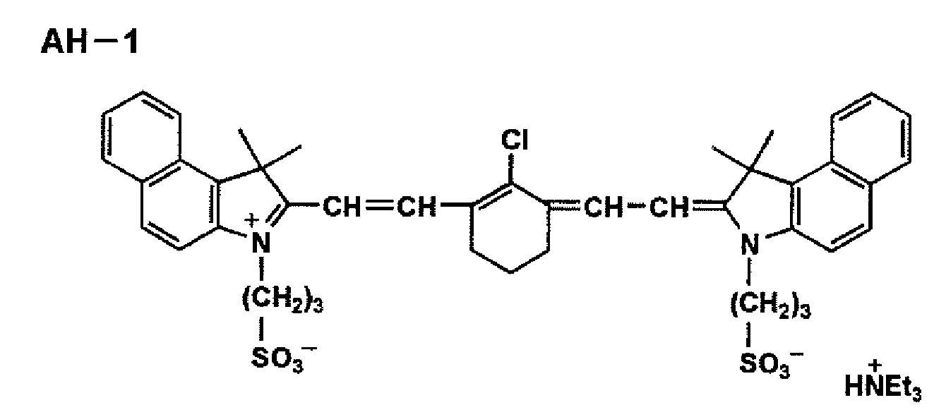
- Exposure was given to the aforesaid materials for a printing plate by the use of SS-830 made by Konica Minolta Holdings Inc. Exposure energy was made to be 250 mJ/cm2, and a solid image and a 50% halftone image were formed under the conditions of 2400 dpi in the lateral direction (dpi means the number of dots per 1 inch = 25.4 cm) and 175-line.
- By using the printing plate thus obtained, printing was carried out (Printing operation Nos. 1 - 7) by installing an air type device on a sheet-fed printing press under the conditions shown in Table 4. In addition, printing was carried out (Printing operation Nos. 10 - 14) by installing on a sheet-fed printing press under the conditions shown in Table 5.
- Printing press: DAIYA 1F-1 made by MITSUBISHI HEAVY INDUSTRIES, LTD.
- Printing paper: Mu coat (made by HOKUETSU PAPER MILS, LTD., 104.7 g/m2)
- Aqueous dampening solution: ASTROMARK 3 (made by Nikken Kagaku Kenkyusho) 2% solution
- Ink: Toyo King HYECOO Magenta (made by TOYO INK MFG. CO. LTD.) was used for printing. After exposure, the printing plate material was installed as it is on the printing cylinder, and the same print-starting sequence as that in the presensitized plate was used for printing.
- A plate life was evaluated for each image thus printed. Results of the evaluation are shown in Table 4 and Table 5.
- The number of prints at the moment when blurring started on a 50% halftone image or on a solid image was used as an index for the plate life. Those having the 10,000 prints or more were accepted.
Table 4 Printing operation No. Air jetting device Distance to paper (mm) Angle formed by paper Plate life (prints) 1 (Comparative Eample) None - - 3,000 2 (Present invention) A 15 45 ° 10,000 or more 3.(present invention) A 55 45 ° 6,000 4 (Present invention) A 15 90 ° 7,000 5 (Present invention) B 15 45 ° 10,000 or more 6 (Present invention) B 55 45 ° 7,000 7 (Present invention) B 15 90 ° 8,000 Table 5 Printing operation No. Scraping device Mounting section Plate life 10 (Comparative Eample) None - 3,000 11 (present invention) Brush First printing unit 10,000 or more 12 (present invention) Unwoven fabric First printing unit 10,000 or more 13 (present invention) Unwoven fabric Total printing units 10,000 or more 14 (present invention) Blade First printing unit 10,000 or more - It is understood from Tables 4 and 5 that printing that is excellent in plate life can be conducted by using the sheet-fed printing press of the invention.
Claims (7)
- A sheet-fed printing press of a single-sided printing type, comprising:a printing unit; anda sheet-feeding device section having a feeder section that feeds a sheet to the printing unit;wherein at least one of the feeder section and the printing unit has a dust-removing means.
- The sheet-fed printing press of claim 1,
wherein the dust-removing means is a means to remove dust by jetting compressed air. - The sheet-fed printing press described of claim 1
wherein the dust-removing means is a means to remove dust by scraping. - The sheet-fed printing press of claim 3, wherein the dust-removing means is at least one type selected from a brush, an unwoven fabric and a blade.
- The sheet-fed printing press of any one of claims 1 - 4, further comprising a dust-collecting means.
- The sheet-fed printing press of claim 5, wherein the dust-removing means and the dust-collecting means are provided in a casing that is totally of a box structure.
- A printing method to conduct double-sided printing by using the sheet-fed printing press of any one of claims 1 - 6, wherein dust is removed from the opposite side on the feeder portion and the aforesaid printing unit, when printing on the opposite side, after supplying blocking-prevention powder on the surface to be printed for the single-sided printing, after single-sided printing.
Applications Claiming Priority (2)
| Application Number | Priority Date | Filing Date | Title |
|---|---|---|---|
| JP2005063517 | 2005-03-08 | ||
| PCT/JP2006/303413 WO2006095582A1 (en) | 2005-03-08 | 2006-02-24 | Sheet-fed printing press and printing method |
Publications (1)
| Publication Number | Publication Date |
|---|---|
| EP1857277A1 true EP1857277A1 (en) | 2007-11-21 |
Family
ID=36953183
Family Applications (1)
| Application Number | Title | Priority Date | Filing Date |
|---|---|---|---|
| EP06714552A Withdrawn EP1857277A1 (en) | 2005-03-08 | 2006-02-24 | Sheet-fed printing press and printing method |
Country Status (4)
| Country | Link |
|---|---|
| US (1) | US20080271624A1 (en) |
| EP (1) | EP1857277A1 (en) |
| JP (1) | JPWO2006095582A1 (en) |
| WO (1) | WO2006095582A1 (en) |
Cited By (1)
| Publication number | Priority date | Publication date | Assignee | Title |
|---|---|---|---|---|
| CN106827831A (en) * | 2017-02-27 | 2017-06-13 | 天津长荣数码科技有限公司 | A kind of sheet-fed code-spraying printer |
Families Citing this family (1)
| Publication number | Priority date | Publication date | Assignee | Title |
|---|---|---|---|---|
| CN108674045A (en) * | 2018-03-30 | 2018-10-19 | 合肥海闻自动化设备有限公司 | A kind of general intelligent Method of printing of multimedium and system |
Family Cites Families (5)
| Publication number | Priority date | Publication date | Assignee | Title |
|---|---|---|---|---|
| DE29702626U1 (en) * | 1997-02-15 | 1997-04-03 | MAN Roland Druckmaschinen AG, 63075 Offenbach | Dust removal system with sheet guiding device |
| DE19903887A1 (en) * | 1998-02-23 | 1999-08-26 | Heidelberger Druckmasch Ag | Process and sheet fed rotary printing machine for printing both front and back sides of a printed sheet |
| ATE316467T1 (en) * | 1998-11-16 | 2006-02-15 | Hans-Peter Koch | SHEET OFFSET PRINTING PROCESS AND SHEET OFFSET PRINTING MACHINE |
| JP3256684B2 (en) * | 1999-07-30 | 2002-02-12 | 株式会社伸興 | Web offset press |
| JP2002292819A (en) * | 2001-03-30 | 2002-10-09 | Fuji Photo Film Co Ltd | On-machine drawing lithographic printing method and device |
-
2006
- 2006-02-24 EP EP06714552A patent/EP1857277A1/en not_active Withdrawn
- 2006-02-24 JP JP2007507043A patent/JPWO2006095582A1/en active Pending
- 2006-02-24 WO PCT/JP2006/303413 patent/WO2006095582A1/en not_active Ceased
- 2006-02-24 US US11/885,698 patent/US20080271624A1/en not_active Abandoned
Non-Patent Citations (1)
| Title |
|---|
| See references of WO2006095582A1 * |
Cited By (1)
| Publication number | Priority date | Publication date | Assignee | Title |
|---|---|---|---|---|
| CN106827831A (en) * | 2017-02-27 | 2017-06-13 | 天津长荣数码科技有限公司 | A kind of sheet-fed code-spraying printer |
Also Published As
| Publication number | Publication date |
|---|---|
| US20080271624A1 (en) | 2008-11-06 |
| WO2006095582A1 (en) | 2006-09-14 |
| JPWO2006095582A1 (en) | 2008-08-14 |
Similar Documents
| Publication | Publication Date | Title |
|---|---|---|
| US6101944A (en) | Method for operating a rotary printing press and device for carrying out the method | |
| US6783228B2 (en) | Digital offset lithographic printing | |
| US7070269B2 (en) | Recording method and apparatus with an intermediate transfer medium based on transfer-type recording mechanism | |
| US20110267389A1 (en) | Methods for printing a print medium, on a web, or a printed sheet output | |
| EP1284184A2 (en) | Image forming method and apparatus | |
| US6470799B2 (en) | Computer-to-cylinder type lithographic printing method and computer-to-cylinder type lithographic printing apparatus | |
| JP2008143180A (en) | Printing machine equipped with washing unit for inking unit | |
| EP1619024A1 (en) | Planographic printing plate material, planographic printing plate, and printing process employing the same | |
| US6416175B2 (en) | Computer-to-cylinder type lithographic printing method and apparatus | |
| US6571706B1 (en) | Method for two-sided printing of a sheet of printing material, and a sheet-fed rotary printing press for performing the method | |
| JP2004155179A (en) | Lithographic printing method from reusable aluminum support | |
| US6055905A (en) | Dual air curtain apparatus for reducing infiltration of dampening solution in a lithographic printing press | |
| EP1857277A1 (en) | Sheet-fed printing press and printing method | |
| JP3427004B2 (en) | Sheet-fed duplex printing machine | |
| US20020121208A1 (en) | Method of preparing a lithographic plate | |
| US5730057A (en) | Cleaning assembly for cleaning printing units of a direct imaging rotary printing press | |
| JPS59204557A (en) | Offset printing method | |
| US20020148375A1 (en) | Cleaning method for recycling a printing substrate by laser ablation | |
| CN1608844A (en) | Method for using repeatable used aluminium carrier to make lithographic printing | |
| US8807029B2 (en) | Plateless lithographic printing | |
| US8276512B2 (en) | Process and apparatus for treating an imaged printing form, re-imageable printing form and machine for processing printing material | |
| EP1232877B1 (en) | Cleaning method for recycling a printing substrate by laser ablation | |
| JP4116760B2 (en) | Planographic printing method | |
| JPWO2001045959A1 (en) | Direct-drawing planographic printing plate material | |
| JPH0717022A (en) | Powder recovery equipment |
Legal Events
| Date | Code | Title | Description |
|---|---|---|---|
| PUAI | Public reference made under article 153(3) epc to a published international application that has entered the european phase |
Free format text: ORIGINAL CODE: 0009012 |
|
| 17P | Request for examination filed |
Effective date: 20070831 |
|
| AK | Designated contracting states |
Kind code of ref document: A1 Designated state(s): DE FR GB IT |
|
| RAP1 | Party data changed (applicant data changed or rights of an application transferred) |
Owner name: KONICA MINOLTA MEDICAL & GRAPHIC, INC. |
|
| RBV | Designated contracting states (corrected) |
Designated state(s): DE FR GB IT |
|
| DAX | Request for extension of the european patent (deleted) | ||
| STAA | Information on the status of an ep patent application or granted ep patent |
Free format text: STATUS: THE APPLICATION IS DEEMED TO BE WITHDRAWN |
|
| 18D | Application deemed to be withdrawn |
Effective date: 20090929 |