EP1855407A2 - Rekonfigurierbare optische Add/Drop-Multiplexing-Vorrichtung mit optischen breitbandigen Eingangs-/Ausgangsschnittstellen - Google Patents
Rekonfigurierbare optische Add/Drop-Multiplexing-Vorrichtung mit optischen breitbandigen Eingangs-/Ausgangsschnittstellen Download PDFInfo
- Publication number
- EP1855407A2 EP1855407A2 EP07107923A EP07107923A EP1855407A2 EP 1855407 A2 EP1855407 A2 EP 1855407A2 EP 07107923 A EP07107923 A EP 07107923A EP 07107923 A EP07107923 A EP 07107923A EP 1855407 A2 EP1855407 A2 EP 1855407A2
- Authority
- EP
- European Patent Office
- Prior art keywords
- optical
- multiplexing device
- drop multiplexing
- modulator
- operating
- Prior art date
- Legal status (The legal status is an assumption and is not a legal conclusion. Google has not performed a legal analysis and makes no representation as to the accuracy of the status listed.)
- Withdrawn
Links
Images


Classifications
-
- H—ELECTRICITY
- H04—ELECTRIC COMMUNICATION TECHNIQUE
- H04J—MULTIPLEX COMMUNICATION
- H04J14/00—Optical multiplex systems
- H04J14/02—Wavelength-division multiplex systems
- H04J14/0201—Add-and-drop multiplexing
- H04J14/0202—Arrangements therefor
- H04J14/021—Reconfigurable arrangements, e.g. reconfigurable optical add/drop multiplexers [ROADM] or tunable optical add/drop multiplexers [TOADM]
-
- H—ELECTRICITY
- H04—ELECTRIC COMMUNICATION TECHNIQUE
- H04J—MULTIPLEX COMMUNICATION
- H04J14/00—Optical multiplex systems
- H04J14/02—Wavelength-division multiplex systems
- H04J14/0201—Add-and-drop multiplexing
- H04J14/0202—Arrangements therefor
- H04J14/0204—Broadcast and select arrangements, e.g. with an optical splitter at the input before adding or dropping
Definitions
- the field of the invention is that of reconfigurable optical add/drop multiplexing devices and, more particularly, that of their input/output interfaces. These devices are better known by their English acronym, ROADM.
- Modern fibre optic telecommunication networks fall into several categories. There are long haul networks deployed country-wide or continent-wide, wide-area networks, also called intermediate networks implemented agglomeration-wide, and finally local area networks, also called distribution networks or access networks. They represent the last link of this chain and complete the routing of the information to the subscriber.
- the topology of the wide-area networks normally comprises communication links interlinked by DSLAM, Digital Subscriber Line Access Multiplexer, type devices.
- DSLAMs are connected to at least one OADM mainly comprising optical add/drop multiplexers and which enable them to handle the following functions:
- wavelength division multiplexing When there is a requirement to transmit in one and the same optical fibre a large number of channels comprising high data rates, wavelength division multiplexing (WDM) is normally used.
- WDM wavelength division multiplexing
- the principle applied consists in coupling into a single optical fibre, by means of appropriate optical devices, several optical carriers with adjacent wavelengths, each transmitting different information channels. Similar optical devices are used at the fibre output to separate the various spectral channels. This way, transmission rates of several tens of Gbits/s can be achieved.
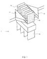
- the DSLAM devices 1 connected to the ROADMs have the architecture of Figure 1. They mainly comprise:
- Each device is linked to the rest of the network by fibre optic links.
- an OADM structure comprises electro-optical reception and transmission devices making it possible to receive, block, transmit or add data on each channel.
- An ROADM using this technology comprises means of dropping and adding data surrounding a multiplexing/demultiplexing assembly comprising a plurality of variable optical attenuators (VOA), each spectral channel disposed in the multiplexing/demultiplexing assembly comprising one of these attenuators.
- VOA variable optical attenuators
- each card comprising an ROADM system becomes a specific card having its own transmission source transmitting at a specific wavelength.
- the term "coloured" devices applies. This thus means that each ROADM operates at a specific wavelength.
- the ROADM according to the invention has a so-called “colourless" architecture comprising only electro-optical elements operating over a waveband that is sufficient to process all the spectral channels of a given spectral band interchangeably.
- the subject of the invention is a reconfigurable optical add/drop multiplexing device, also called ROADM, capable of operating for any spectral channel belonging to a spectral band comprising a plurality of spectral channels, said device comprising at least one first opto-electronic assembly comprising a fibre optic input port, a fibre optic output port, at least one optical gate and optical coupling means, said gate and said means being capable of operating for all of said spectral channels, the coupling means being coupled to at least:
- ROADM reconfigurable optical add/drop multiplexing device
- the optical modulator or the photon detector are optical electro-absorption modulators that can operate either in transmission mode or in reflection mode.
- At least one modulator comprises a semiconductor optical amplifier.
- the WDM-type transmission source is a distributed Bragg reflector laser diode.
- the coupling means of the first opto-electronic assembly comprise an optical circulator linked at least to the input and output ports and to the optical modulator.
- the optical circulator is also linked to the photon detector.
- the first opto-electronic assembly comprises at least one multiplexing/demultiplexing device linked at least to the input and output ports, the coupling means being positioned on one of the channels.
- An ROADM needs to be able to perform the following operations on a signal arriving at its input port:
- a spectral band used in optical telecommunications has a width of a few tens of nanometres and the wavelengths used are separated by less than one nanometre.
- the wavelengths used are normally located in the near-infrared, around 1450 nanometres or 1550 nanometres.
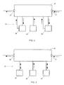
- FIGS 2 and 3 represent the general principle of ROADM according to the invention comprising elements operating either by transmission or by reflection capable of providing the above functions.
- Said ROADMs 10 comprise at least:
- optical electro-absorption modulators can advantageously be used, also known by the French acronym MEA or English acronym EAM.
- the principle of operation of the electro-absorption modulators is based on modifications of the absorption spectrum of a semiconductor subjected to an electrical field. It is in the vicinity of the absorption edge, at the point where the drift of the absorption relative to the wavelength is greatest, that this effect is most effective.
- An increase in the electrical field shifts the absorption edge towards the higher wavelengths and consequently increases the absorption of the light passing through the conductor.
- the modulator is also possible to use the modulator as a photodetector.
- the absorption of an optical signal modulated by the modulator leads to the transmission of an induced current, the amplitude of which has a modulation matching that of the initial optical signal.
- the modulator When the light beam passes through the modulator, it is said to operate by transmission; when the light beam is reflected by the rear face of the modulator, it is said to operate by reflection. In these conditions, the modulation is doubled.
- One of the benefits of the EAM is that it is operational over a spectral band compatible with the spectral bands of optical telecommunications. Consequently, a judicious choice of its various parameters can render it "colourless".
- a modulator cannot transmit a modulated signal on its own. It must necessarily have added to it a WDM-type light source. This can possibly be a distributed Bragg reflector laser diode. The benefit of this type of source is that it is possible to adjust it exactly to the transmission wavelength. Thus, without changing the source, it is possible to adapt an ROADM card according to the invention to a specific wavelength of a given spectral band.
- a modulator a semiconductor optical amplifier, also called SOA. By controlling the gain of this amplifier, it is thus possible to amplify the signal or to stop it.
- SOA semiconductor optical amplifier
- the assembly can be produced either using discrete components, or in hybrid fashion on the same substrate.
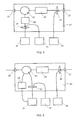
- Figures 4, 5 and 6 propose three variants of one and the same theoretical ROADM architecture.
- the main characteristic of this architecture is that the first opto-electronic assembly comprises an optical circulator 23 linked at least to the input ports 21 and output ports 22 and to the optical modulator 30.
- Figure 4 represents a first variant of this type of architecture where the modulator operates by reflection.
- the first opto-electronic assembly 20 comprises:
- This first architecture can have several variants.
- the modulator no longer operates by reflection but by transmission. It is thus coupled to the circulator 23 by two different ports, an input port and an output port.
- the optical gate comprises a blocking element 24, which can be an EAM, and an amplifying element 28 which can be an SOA. Obviously, the architectures described in Figures 5 and 6 can be combined.
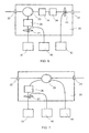
- Figures 7, 8 and 9 propose three variants of the same theoretical ROADM architecture.
- the main characteristic of this architecture is that the first opto-electronic assembly comprises a central optical circulator 23 linked to at least the input ports 21 and output ports 22, to the optical modulator 30 and to the photon detector 50.
- Figure 7 represents a first variant of this type of architecture.
- the first opto-electronic assembly 20 comprises:
- This second architecture can have a number of variants.
- the photon detector 50 no longer operates by reflection but by transmission. It is thus coupled to the circulator 23 by two different ports, an input port and an output port.
- the modulator 30 no longer operates by reflection but by transmission. It is thus coupled to the circulator by two different ports, an input port and an output port.
- the architectures described in figures 8 and 9 can be combined.
- Figures 10 and 11 propose two variants of one and the same theoretical ROADM architecture.
- the main characteristic of this architecture is that the first opto-electronic assembly 20 comprises a multiplexer/demultiplexer assembly 290 and 291 positioned between the input 21 and output 22 ports.
- each spectral channel disposed between the multiplexing/demultiplexing assembly can comprise the functions of an ROADM produced by means of the optical and opto-electronic components described previously.
- Secondary branch connections 293 linked to other opto-electronics devices that are not shown can also be inserted into the first opto-electronic assembly 20, as can secondary multiplexing/demultiplexing devices 292.
- the modulator 30 operates by reflection
- the optical modulator 30 operates by transmission.
Landscapes
- Engineering & Computer Science (AREA)
- Computer Networks & Wireless Communication (AREA)
- Signal Processing (AREA)
- Optical Communication System (AREA)
Applications Claiming Priority (1)
| Application Number | Priority Date | Filing Date | Title |
|---|---|---|---|
| FR0604183A FR2901078B1 (fr) | 2006-05-11 | 2006-05-11 | Dispositif reconfigurable de multiplexage optique a insertion/extraction comportant des interfaces d'entree/sortie optiques a bandes larges |
Publications (2)
| Publication Number | Publication Date |
|---|---|
| EP1855407A2 true EP1855407A2 (de) | 2007-11-14 |
| EP1855407A3 EP1855407A3 (de) | 2008-12-17 |
Family
ID=37668157
Family Applications (1)
| Application Number | Title | Priority Date | Filing Date |
|---|---|---|---|
| EP07107923A Withdrawn EP1855407A3 (de) | 2006-05-11 | 2007-05-10 | Rekonfigurierbare optische Add/Drop-Multiplexing-Vorrichtung mit optischen breitbandigen Eingangs-/Ausgangsschnittstellen |
Country Status (2)
| Country | Link |
|---|---|
| EP (1) | EP1855407A3 (de) |
| FR (1) | FR2901078B1 (de) |
Citations (2)
| Publication number | Priority date | Publication date | Assignee | Title |
|---|---|---|---|---|
| EP1265451A2 (de) * | 2001-06-07 | 2002-12-11 | Innovance Inc. | Architektur für optische Transport-Netzwerken |
| EP1496636A1 (de) * | 2003-07-09 | 2005-01-12 | Lucent Technologies Inc. | Optische Vorrichtung mit abstimmbarem kohärentem Empfänger |
Family Cites Families (4)
| Publication number | Priority date | Publication date | Assignee | Title |
|---|---|---|---|---|
| US20030002104A1 (en) * | 2001-06-29 | 2003-01-02 | Caroli Carl A. | Wavelength-selective add/drop arrangement for optical communication systems |
| US7136589B2 (en) * | 2002-07-05 | 2006-11-14 | Hon Hai Precision Ind. Co., Ltd | Re-configurable optical add-drop multiplexer |
| US7161964B2 (en) * | 2002-09-11 | 2007-01-09 | Lucent Technologies Inc. | Reconfigurable ADD/DROP, multiplexer/demultiplexer using a transceiver with loop-back function |
| US7283701B2 (en) * | 2003-08-01 | 2007-10-16 | Optium Corporation | Optical fiber transmission system with increased effective modal bandwidth transmission |
-
2006
- 2006-05-11 FR FR0604183A patent/FR2901078B1/fr not_active Expired - Fee Related
-
2007
- 2007-05-10 EP EP07107923A patent/EP1855407A3/de not_active Withdrawn
Patent Citations (2)
| Publication number | Priority date | Publication date | Assignee | Title |
|---|---|---|---|---|
| EP1265451A2 (de) * | 2001-06-07 | 2002-12-11 | Innovance Inc. | Architektur für optische Transport-Netzwerken |
| EP1496636A1 (de) * | 2003-07-09 | 2005-01-12 | Lucent Technologies Inc. | Optische Vorrichtung mit abstimmbarem kohärentem Empfänger |
Also Published As
| Publication number | Publication date |
|---|---|
| FR2901078A1 (fr) | 2007-11-16 |
| EP1855407A3 (de) | 2008-12-17 |
| FR2901078B1 (fr) | 2008-07-04 |
Similar Documents
| Publication | Publication Date | Title |
|---|---|---|
| US10194221B2 (en) | High capacity fiber-optic integrated transmission and switching systems | |
| US6185023B1 (en) | Optical add-drop multiplexers compatible with very dense WDM optical communication systems | |
| US20120087658A1 (en) | Wavelength Selective Switch Band Aggregator and Band Deaggregator and Systems and Methods Using Same | |
| CN100420173C (zh) | 光通信系统 | |
| CN1483155A (zh) | 具有双向光服务信道的双向wdm光通信系统 | |
| EP1078487B1 (de) | Optische dicht-wdm-multiplexer und -demultiplexer | |
| CN103460628A (zh) | 光传输装置 | |
| JP2001103009A (ja) | 通信システム | |
| US11870552B2 (en) | Apparatus and method for coherent optical multiplexing 1+1 protection | |
| US9065589B2 (en) | Apparatus and method for operating a wavelength division multiplexing access network | |
| US8861966B2 (en) | Method and system for band blocking in an optical telecommunication network | |
| EP4645896A1 (de) | Optischer verzweiger eines passiven optischen netzwerks und optisches signalverarbeitungsverfahren dafür | |
| US20060198636A1 (en) | Wavelength grid for DWDM | |
| EP1855407A2 (de) | Rekonfigurierbare optische Add/Drop-Multiplexing-Vorrichtung mit optischen breitbandigen Eingangs-/Ausgangsschnittstellen | |
| US20140376912A1 (en) | Optical access network | |
| Earnshaw et al. | Integrated Reconfigurabie Optical Wavelength Add-Drop Multiplexer | |
| CA2440442C (en) | Signal addition to a wave division multiplex system | |
| Wong et al. | OPN01-6: Enabling security countermeasure and service restoration in passive optical networks | |
| WO2004036794A1 (en) | Optical modulation devices | |
| EP1096713A2 (de) | Optischer Add/drop-Multiplexer | |
| US7133612B1 (en) | Bidirectional WDM transmission system having transmission format for reducing adverse effects of filter concatonation | |
| Singh | A Novel Architecture of N× N Bidirectional Reconfigurable Multiwavelength Optical Cross Connect | |
| KR100908239B1 (ko) | 채널 통과/결합 광 모듈 및 이를 이용한 oadm노드에서의 채널 통과/결합 방법 | |
| EP4657879A1 (de) | Optischer verzweiger eines passiven optischen netzwerks und optisches signalverarbeitungsverfahren | |
| US20030185511A1 (en) | Optical grating device |
Legal Events
| Date | Code | Title | Description |
|---|---|---|---|
| PUAI | Public reference made under article 153(3) epc to a published international application that has entered the european phase |
Free format text: ORIGINAL CODE: 0009012 |
|
| AK | Designated contracting states |
Kind code of ref document: A2 Designated state(s): AT BE BG CH CY CZ DE DK EE ES FI FR GB GR HU IE IS IT LI LT LU LV MC MT NL PL PT RO SE SI SK TR |
|
| AX | Request for extension of the european patent |
Extension state: AL BA HR MK YU |
|
| RIN1 | Information on inventor provided before grant (corrected) |
Inventor name: DORGEUILLE, FRANCOIS Inventor name: CHIARONI, DOMINIQUE Inventor name: LE SAUZE, NICOLAS Inventor name: KAZMIERSKI, CHRISTOPHE Inventor name: SILLARD, HELENE |
|
| RAP1 | Party data changed (applicant data changed or rights of an application transferred) |
Owner name: ALCATEL LUCENT |
|
| PUAL | Search report despatched |
Free format text: ORIGINAL CODE: 0009013 |
|
| AK | Designated contracting states |
Kind code of ref document: A3 Designated state(s): AT BE BG CH CY CZ DE DK EE ES FI FR GB GR HU IE IS IT LI LT LU LV MC MT NL PL PT RO SE SI SK TR |
|
| AX | Request for extension of the european patent |
Extension state: AL BA HR MK RS |
|
| 17P | Request for examination filed |
Effective date: 20090311 |
|
| 17Q | First examination report despatched |
Effective date: 20090414 |
|
| AKX | Designation fees paid |
Designated state(s): AT BE BG CH CY CZ DE DK EE ES FI FR GB GR HU IE IS IT LI LT LU LV MC MT NL PL PT RO SE SI SK TR |
|
| RAP1 | Party data changed (applicant data changed or rights of an application transferred) |
Owner name: ALCATEL LUCENT |
|
| 111Z | Information provided on other rights and legal means of execution |
Free format text: AT BE BG CH CY CZ DE DK EE ES FI FR GB GR HU IE IS IT LI LT LU LV MC MT NL PL PT RO SE SI SK TR Effective date: 20130410 |
|
| RAP1 | Party data changed (applicant data changed or rights of an application transferred) |
Owner name: ALCATEL LUCENT |
|
| D11X | Information provided on other rights and legal means of execution (deleted) | ||
| STAA | Information on the status of an ep patent application or granted ep patent |
Free format text: STATUS: THE APPLICATION IS DEEMED TO BE WITHDRAWN |
|
| 18D | Application deemed to be withdrawn |
Effective date: 20161129 |