EP1855293A1 - Open protective tube - Google Patents
Open protective tube Download PDFInfo
- Publication number
- EP1855293A1 EP1855293A1 EP04805080A EP04805080A EP1855293A1 EP 1855293 A1 EP1855293 A1 EP 1855293A1 EP 04805080 A EP04805080 A EP 04805080A EP 04805080 A EP04805080 A EP 04805080A EP 1855293 A1 EP1855293 A1 EP 1855293A1
- Authority
- EP
- European Patent Office
- Prior art keywords
- layer
- protective tube
- aluminium foil
- aluminium
- plastic material
- Prior art date
- Legal status (The legal status is an assumption and is not a legal conclusion. Google has not performed a legal analysis and makes no representation as to the accuracy of the status listed.)
- Withdrawn
Links
- 230000001681 protective effect Effects 0.000 title claims abstract description 21
- 239000004033 plastic Substances 0.000 claims abstract description 12
- 239000005030 aluminium foil Substances 0.000 claims abstract description 11
- 239000004411 aluminium Substances 0.000 claims abstract description 10
- XAGFODPZIPBFFR-UHFFFAOYSA-N aluminium Chemical compound [Al] XAGFODPZIPBFFR-UHFFFAOYSA-N 0.000 claims abstract description 10
- 229910052782 aluminium Inorganic materials 0.000 claims abstract description 10
- 239000000463 material Substances 0.000 claims abstract description 9
- 229920000728 polyester Polymers 0.000 claims description 6
- 239000004952 Polyamide Substances 0.000 claims description 3
- 229920002647 polyamide Polymers 0.000 claims description 3
- 229920006149 polyester-amide block copolymer Polymers 0.000 claims description 3
- 238000009413 insulation Methods 0.000 description 8
- 238000005259 measurement Methods 0.000 description 6
- 238000012216 screening Methods 0.000 description 6
- 238000001228 spectrum Methods 0.000 description 3
- 239000000853 adhesive Substances 0.000 description 2
- 230000001070 adhesive effect Effects 0.000 description 2
- 229920006267 polyester film Polymers 0.000 description 2
- 238000003466 welding Methods 0.000 description 2
- 238000005299 abrasion Methods 0.000 description 1
- 239000000919 ceramic Substances 0.000 description 1
- 239000004020 conductor Substances 0.000 description 1
- 238000010924 continuous production Methods 0.000 description 1
- 229910052500 inorganic mineral Inorganic materials 0.000 description 1
- 244000239634 longleaf box Species 0.000 description 1
- 239000011707 mineral Substances 0.000 description 1
- 238000012986 modification Methods 0.000 description 1
- 230000004048 modification Effects 0.000 description 1
- 230000035945 sensitivity Effects 0.000 description 1
Images

Classifications
-
- B—PERFORMING OPERATIONS; TRANSPORTING
- B32—LAYERED PRODUCTS
- B32B—LAYERED PRODUCTS, i.e. PRODUCTS BUILT-UP OF STRATA OF FLAT OR NON-FLAT, e.g. CELLULAR OR HONEYCOMB, FORM
- B32B1/00—Layered products having a non-planar shape
- B32B1/08—Tubular products
-
- B—PERFORMING OPERATIONS; TRANSPORTING
- B60—VEHICLES IN GENERAL
- B60R—VEHICLES, VEHICLE FITTINGS, OR VEHICLE PARTS, NOT OTHERWISE PROVIDED FOR
- B60R16/00—Electric or fluid circuits specially adapted for vehicles and not otherwise provided for; Arrangement of elements of electric or fluid circuits specially adapted for vehicles and not otherwise provided for
- B60R16/02—Electric or fluid circuits specially adapted for vehicles and not otherwise provided for; Arrangement of elements of electric or fluid circuits specially adapted for vehicles and not otherwise provided for electric constitutive elements
- B60R16/0207—Wire harnesses
- B60R16/0215—Protecting, fastening and routing means therefor
-
- F—MECHANICAL ENGINEERING; LIGHTING; HEATING; WEAPONS; BLASTING
- F16—ENGINEERING ELEMENTS AND UNITS; GENERAL MEASURES FOR PRODUCING AND MAINTAINING EFFECTIVE FUNCTIONING OF MACHINES OR INSTALLATIONS; THERMAL INSULATION IN GENERAL
- F16L—PIPES; JOINTS OR FITTINGS FOR PIPES; SUPPORTS FOR PIPES, CABLES OR PROTECTIVE TUBING; MEANS FOR THERMAL INSULATION IN GENERAL
- F16L57/00—Protection of pipes or objects of similar shape against external or internal damage or wear
- F16L57/04—Protection of pipes or objects of similar shape against external or internal damage or wear against fire or other external sources of extreme heat
-
- F—MECHANICAL ENGINEERING; LIGHTING; HEATING; WEAPONS; BLASTING
- F16—ENGINEERING ELEMENTS AND UNITS; GENERAL MEASURES FOR PRODUCING AND MAINTAINING EFFECTIVE FUNCTIONING OF MACHINES OR INSTALLATIONS; THERMAL INSULATION IN GENERAL
- F16L—PIPES; JOINTS OR FITTINGS FOR PIPES; SUPPORTS FOR PIPES, CABLES OR PROTECTIVE TUBING; MEANS FOR THERMAL INSULATION IN GENERAL
- F16L57/00—Protection of pipes or objects of similar shape against external or internal damage or wear
- F16L57/06—Protection of pipes or objects of similar shape against external or internal damage or wear against wear
-
- H—ELECTRICITY
- H02—GENERATION; CONVERSION OR DISTRIBUTION OF ELECTRIC POWER
- H02G—INSTALLATION OF ELECTRIC CABLES OR LINES, OR OF COMBINED OPTICAL AND ELECTRIC CABLES OR LINES
- H02G3/00—Installations of electric cables or lines or protective tubing therefor in or on buildings, equivalent structures or vehicles
- H02G3/02—Details
- H02G3/04—Protective tubing or conduits, e.g. cable ladders or cable troughs
- H02G3/0462—Tubings, i.e. having a closed section
- H02G3/0481—Tubings, i.e. having a closed section with a circular cross-section
-
- Y—GENERAL TAGGING OF NEW TECHNOLOGICAL DEVELOPMENTS; GENERAL TAGGING OF CROSS-SECTIONAL TECHNOLOGIES SPANNING OVER SEVERAL SECTIONS OF THE IPC; TECHNICAL SUBJECTS COVERED BY FORMER USPC CROSS-REFERENCE ART COLLECTIONS [XRACs] AND DIGESTS
- Y10—TECHNICAL SUBJECTS COVERED BY FORMER USPC
- Y10T—TECHNICAL SUBJECTS COVERED BY FORMER US CLASSIFICATION
- Y10T428/00—Stock material or miscellaneous articles
- Y10T428/13—Hollow or container type article [e.g., tube, vase, etc.]
- Y10T428/1352—Polymer or resin containing [i.e., natural or synthetic]
- Y10T428/1355—Elemental metal containing [e.g., substrate, foil, film, coating, etc.]
- Y10T428/1359—Three or more layers [continuous layer]
Definitions
- protection tubes are used to protect electrical conductors and other components, especially in the automobile industry.
- the protection tubes In the first place, the protection tubes must have great mechanical and thermal resistance, as they are used in areas of high temperature and where they are subjected to abrasion.
- these protection tubes must include noise insulation characteristics, as it would be unacceptable for these protection tubes to produce noise when used in automobiles.
- protection tubes are resistance to high temperatures.
- protective tubes formed by a series of layers, for example a first layer formed by a plurality of a plastic material or mineral threads knitted to one another and a second layer of aluminium film on said first layer. These protection tubes are used to achieve good electromagnetic and thermal insulation.
- the open protective tube of the invention has a first layer comprising a plurality of plastic threads which are woven to one another and a second layer of aluminium foil, and is characterised in that the said aluminium foil comprises a plastic material film and an aluminium film, said plastic material film being welded to the stated first layer.
- the protective tube is open along its length making the assembly significantly easier.
- said plastic material comprises polyester.
- the threads that comprise the first layer are made from polyester or polyester and polyamide.
- the aluminium film can be located on the inner part of the tube.
- Figure 1 shows a transverse section view of the protective tube of the invention
- Figure 2 is a graph in which the results of the trials are shown in order to demonstrate the electromagnetic insulation of the protective tube of this present invention.
- the protective tube of the invention is made up of two layers:
- the aluminium foil layer (2) is made from a polyester film (3) and an aluminium film (4), said polyester film (3) being welded to said first layer (1).
- the thickness of the polyester layer (3) can be 23 microns and the thickness of the aluminium foil (4) can be from 9 to 25 microns, with a total weight for the aluminium layer (2) being 2.6 g/m.
- the welding of the aluminium foil layer (2) on the first layer (1) is by preference made at a temperature of between 240° C and 540° C said welding being carried out with a continuous process at a speed of between 1 and 20 m/min.
- Said first layer (1) has, for example, has a weight of 17.26 g/m and a thickness of 1.0 mm ⁇ 0.3 mm for a width of 50 mm.
- the tube of this present invention can have a weight of 19.86 g/m and a thickness of 1.0 mm ⁇ 0.3 mm for a diameter of 7 mm.
- the order of the layers can be inverted placing the aluminium on the inside and the woven layer on the outside.
- a two-metre long wire, connected to the generator acted as the electromagnetic wave transmitter.
- a measurement of the power received is carried out. After the 15 cm aerial is screened with the trial tube (sample) and the power received is again measured. The difference between both powers is a screening measurement of the sample.
- Table I Time (min) transmitter T (°C) internal T (°C) ambient T Delta T (°C) 0 23 23 24 0 2 129 64 78 65 4 264 81 96 183 6 291 77 87 214 8 316 83 93 233 10 329 87 98 242 15 363 98 109 265 20 384 105 119 279 25 394 107 128 287 30 396 109 130 287 35 398 110 135 288 40 400 109 139 291 50 400 116 143 284 60 400 118 152 282
Landscapes
- Engineering & Computer Science (AREA)
- General Engineering & Computer Science (AREA)
- Mechanical Engineering (AREA)
- Architecture (AREA)
- Civil Engineering (AREA)
- Structural Engineering (AREA)
- Laminated Bodies (AREA)
Abstract
The invention refers to an open protective tube, especially for the mechanical and thermal protection of electrical conducts and other components in automobiles.
The open protective tube comprising a first layer (1) with a plurality of plastic threads which are woven to one another and a second layer of aluminium foil (2), and is characterised in that the said aluminium foil (2) comprises a plastic material film (3) and an aluminium film (4), said plastic material film (3) being welded to the stated first layer (1).
Description
- At the present time protection tubes are used to protect electrical conductors and other components, especially in the automobile industry.
- These protection tubes must combine different characteristics that make them suitable for these types of uses.
- In the first place, the protection tubes must have great mechanical and thermal resistance, as they are used in areas of high temperature and where they are subjected to abrasion.
- In addition, these protection tubes must include noise insulation characteristics, as it would be unacceptable for these protection tubes to produce noise when used in automobiles.
- In addition, these protective tubes must be easy to install.
- In order to solve these disadvantages there are a great number of protection tubes that combine these characteristics and which are currently used to protect cables in automobiles.
- One of the most important characteristics that these protection tubes must have is resistance to high temperatures. At the present time there are protective tubes formed by a series of layers, for example a first layer formed by a plurality of a plastic material or mineral threads knitted to one another and a second layer of aluminium film on said first layer. These protection tubes are used to achieve good electromagnetic and thermal insulation.
- In this case, the fixing of the layer of aluminium film to the second layer with adhesive is currently known. These types of protective tube have the disadvantage that they cannot stand high temperatures due to the fact that the adhesives do not withstand high temperatures with the lack of suitable adherence between the aluminium film and the first previously stated layer.
- With the open protection tube of the invention the stated disadvantages are resolved, presenting other advantages which will be described.
- The open protective tube of the invention has a first layer comprising a plurality of plastic threads which are woven to one another and a second layer of aluminium foil, and is characterised in that the said aluminium foil comprises a plastic material film and an aluminium film, said plastic material film being welded to the stated first layer.
- The protective tube is open along its length making the assembly significantly easier.
- According to the preferred embodiment, said plastic material comprises polyester.
- According to alternative embodiments, the threads that comprise the first layer are made from polyester or polyester and polyamide.
- If required, the aluminium film can be located on the inner part of the tube.
- With the protective tube of this present invention excellent electromagnetic and thermal insulation is achieved, supporting high temperatures, and excellent adherence between the first and second layers and with great ease in assembly.
- In order to give a greater understanding of that which has been stated some drawings are included in which an outline of a practical embodiment is made which is made by way of being an example and without being by way of limitation.
- Figure 1 shows a transverse section view of the protective tube of the invention;
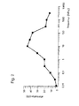
- Figure 2 is a graph in which the results of the trials are shown in order to demonstrate the electromagnetic insulation of the protective tube of this present invention.
- As and how can be seen in the only figure, the protective tube of the invention is made up of two layers:
- A first layer (1) comprising of a plurality of polyester or polyester and polyamide threads that are woven to each other; and
- A second layer of aluminium foil (2) over said first layer (1).
- The aluminium foil layer (2) is made from a polyester film (3) and an aluminium film (4), said polyester film (3) being welded to said first layer (1). For example, the thickness of the polyester layer (3) can be 23 microns and the thickness of the aluminium foil (4) can be from 9 to 25 microns, with a total weight for the aluminium layer (2) being 2.6 g/m.
- The welding of the aluminium foil layer (2) on the first layer (1) is by preference made at a temperature of between 240° C and 540° C said welding being carried out with a continuous process at a speed of between 1 and 20 m/min.
- Said first layer (1) has, for example, has a weight of 17.26 g/m and a thickness of 1.0 mm ± 0.3 mm for a width of 50 mm.
- For example the tube of this present invention, can have a weight of 19.86 g/m and a thickness of 1.0 mm ± 0.3 mm for a diameter of 7 mm.
- The order of the layers can be inverted placing the aluminium on the inside and the woven layer on the outside.
- As has been previously stated, with the protective tube of the present invention excellent electromagnetic and thermal insulation is achieved, even at high temperatures.
- In order to demonstrate this statement several trials have been carried out on the protective tube of this present invention.
- In order to assess the electromagnetic insulation of the protective tube of the present invention a spectrum analyser (Agilent E-4402B) was used with an internal radiofrequency generator.
- A two-metre long wire, connected to the generator acted as the electromagnetic wave transmitter. A screened coaxial cable, parallel to the wire separated by some 2 cm, and with a length of 15 cm without screening, acted as the aerial, and was connected to the spectrum analyser.
- First, a measurement of the power received is carried out. After the 15 cm aerial is screened with the trial tube (sample) and the power received is again measured. The difference between both powers is a screening measurement of the sample.
- It must be taken into account that the majority of measurements are of minimum screening, and that the real screening is always greater than that of the graphs. This is a consequence of the fact that the measurement with the screened aerial almost always gives a zero power received.
- If the power transmitted were higher, or the sensitivity of the spectrum analyser were greater, measurements could be carried out in which the power received with the screening were different to zero, and therefore, maximum screening values will be the result.
- The results of the trial are shown in the graph in figure 2.
- In order to check the characteristics of the thermal insulation a trial was carried out. The main objective of this trial was to study the performance of the protection tube under an external heat source.
- In this case, it is very important to control the ambient temperature whilst the trial is being carried out in order to obtain reliable performance. Depending on the ambient temperature, the thermal insulation results can change.
- The trial was carried out in accordance with the BUNDY SA 01-006 R4 standard, under the following conditions:
- Radiant heat source: 400° C
- Distance: 35 mm under the heat source
- Dimensions of the heat box: 420 mm x 420 mm x 245 mm
- Duration of the trial: 1 hour
- Description of the thermocouples:
- Internal thermocouple: Position of the thermocouple touching the external surface of the ceramic cylinder, at the middle point of the length (15 cm) and measuring the temperature on the inside of the protective tube.
- Ambient thermocouple: A thermocouple for the measurement of the ambient temperature in the heat box.
- During the trial all of the temperatures were recorded.
- Delta T is calculated as the difference between the T of the transmitter and the T on the inside of the tube:

- The results of the trial are shown in the attached Table I.
Table I Time (min) transmitter T (°C) internal T (°C) ambient T Delta T (°C) 0 23 23 24 0 2 129 64 78 65 4 264 81 96 183 6 291 77 87 214 8 316 83 93 233 10 329 87 98 242 15 363 98 109 265 20 384 105 119 279 25 394 107 128 287 30 396 109 130 287 35 398 110 135 288 40 400 109 139 291 50 400 116 143 284 60 400 118 152 282 - In spite of the fact that reference has been made to a specific embodiment of the invention, it is clear for an expert in the subject matter that the protection tube described is capable of being used with numerous variations and modifications, and all of the details mentioned can be substituted for others that are technically equivalent, without departing from the scope of the protection defined by the attached claims.
Claims (5)
- Open protective tube comprising a first layer (1) with a plurality of plastic threads which are woven to one another and a second layer of aluminium foil (2), and is characterised in that the said aluminium foil (2) comprises a plastic material film (3) and an aluminium film (4), said plastic material film (3) being welded to the stated first layer (1).
- Protective tube according to Claim 1, characterised in that said plastic material film (3) is made from polyester.
- Protective tube according to with Claim 1, characterised in that the threads that comprise said first layer (1) are made from polyester.
- Protective tube according to with Claim 1, characterised in that the threads that comprise said first layer (1) are made from polyester and polyamide.
- Protective tube according to Claim 1, characterised in that the aluminium foil (4) is located on the inside of the tube.
Applications Claiming Priority (1)
| Application Number | Priority Date | Filing Date | Title |
|---|---|---|---|
| PCT/ES2004/000537 WO2006061441A1 (en) | 2004-12-02 | 2004-12-02 | Open protective tube |
Publications (1)
| Publication Number | Publication Date |
|---|---|
| EP1855293A1 true EP1855293A1 (en) | 2007-11-14 |
Family
ID=36577681
Family Applications (1)
| Application Number | Title | Priority Date | Filing Date |
|---|---|---|---|
| EP04805080A Withdrawn EP1855293A1 (en) | 2004-12-02 | 2004-12-02 | Open protective tube |
Country Status (4)
| Country | Link |
|---|---|
| US (1) | US20080311325A1 (en) |
| EP (1) | EP1855293A1 (en) |
| MX (1) | MX2007008095A (en) |
| WO (1) | WO2006061441A1 (en) |
Cited By (2)
| Publication number | Priority date | Publication date | Assignee | Title |
|---|---|---|---|---|
| CN102278569A (en) * | 2011-06-10 | 2011-12-14 | 衡阳凌云特种材料有限公司 | Anti-radiation high temperature resistant heat insulating composite bushing and preparation method |
| DE102014119751A1 (en) | 2014-12-31 | 2016-06-30 | Michael Lindner | Method for producing a protective device |
Families Citing this family (2)
| Publication number | Priority date | Publication date | Assignee | Title |
|---|---|---|---|---|
| WO2003051077A1 (en) | 2001-12-05 | 2003-06-19 | Thomson Licensing S.A. | Method and apparatus for paging a mobile terminal in a wireless lan |
| JP2017152401A (en) * | 2017-05-01 | 2017-08-31 | 三和レジン工業株式会社 | Coating material |
Family Cites Families (6)
| Publication number | Priority date | Publication date | Assignee | Title |
|---|---|---|---|---|
| US4330017A (en) * | 1977-04-22 | 1982-05-18 | Nissan Motor Company, Limited | Rubber hose for automotive fuel line |
| US4327248A (en) * | 1980-10-06 | 1982-04-27 | Eaton Corporation | Shielded electrical cable |
| US5329064A (en) * | 1992-10-02 | 1994-07-12 | Belden Wire & Cable Company | Superior shield cable |
| DE19742223C2 (en) * | 1997-09-24 | 1999-11-18 | Univ Dresden Tech | Pipe insulation made of polyester fibers and admixture fibers |
| US6433273B1 (en) * | 2000-10-20 | 2002-08-13 | The Zippertubing Co. | Heat-shielding jacket |
| US7410550B2 (en) * | 2003-12-11 | 2008-08-12 | Sherwin Michael J | Flexible insulating sleeve |
-
2004
- 2004-12-02 MX MX2007008095A patent/MX2007008095A/en unknown
- 2004-12-02 WO PCT/ES2004/000537 patent/WO2006061441A1/en not_active Ceased
- 2004-12-02 EP EP04805080A patent/EP1855293A1/en not_active Withdrawn
- 2004-12-02 US US11/883,376 patent/US20080311325A1/en not_active Abandoned
Non-Patent Citations (1)
| Title |
|---|
| See references of WO2006061441A1 * |
Cited By (3)
| Publication number | Priority date | Publication date | Assignee | Title |
|---|---|---|---|---|
| CN102278569A (en) * | 2011-06-10 | 2011-12-14 | 衡阳凌云特种材料有限公司 | Anti-radiation high temperature resistant heat insulating composite bushing and preparation method |
| DE102014119751A1 (en) | 2014-12-31 | 2016-06-30 | Michael Lindner | Method for producing a protective device |
| DE102014119751B4 (en) | 2014-12-31 | 2017-03-02 | Michael Lindner | Method for producing a protective device |
Also Published As
| Publication number | Publication date |
|---|---|
| MX2007008095A (en) | 2007-09-19 |
| US20080311325A1 (en) | 2008-12-18 |
| WO2006061441A1 (en) | 2006-06-15 |
Similar Documents
| Publication | Publication Date | Title |
|---|---|---|
| JP5832007B2 (en) | Infrared sensor and manufacturing method thereof | |
| AU650155B2 (en) | Conformal circuit for structural health monitoring and assessment | |
| US7752909B2 (en) | Flow sensor with non-contact temperature detecting means | |
| CN101657707B (en) | Radiation thermometer | |
| US20140314118A1 (en) | Blackbody function | |
| US20170363474A1 (en) | Infrared sensor and method for electrical monitoring | |
| US20140376594A1 (en) | Temperature sensing assembly for measuring temperature of a surface of a structure | |
| US9927303B2 (en) | Temperature sensor for high temperature | |
| US6079875A (en) | Apparatus for measuring the temperature of an object with a temperature sensor and method of making the temperature sensor | |
| CA2490777A1 (en) | A vacuum insulated refrigerator cabinet and method for assessing thermal conductivity thereof | |
| TW201344166A (en) | Infrared sensor | |
| US7276697B2 (en) | Infrared apparatus | |
| EP2113709A1 (en) | Heat protection tube | |
| EP1180669A1 (en) | Pyrometric measurement device of the temperature of a cooking vessel | |
| US20080311325A1 (en) | Open Protective Tube | |
| US4365229A (en) | High temperature sensor | |
| US20170184427A1 (en) | Sensor node package | |
| WO2015066494A2 (en) | Broadband waveguide | |
| CN120212853A (en) | A low temperature strain stress testing device and method for infrared detector chip | |
| CN113167752B (en) | Measuring mechanism | |
| US20230296445A1 (en) | Stacked Active Thick Film Device | |
| EP4158293B1 (en) | Method and vacuum apparatus temperature sensor assembly | |
| US6301775B1 (en) | Alumina encapsulated strain gage, not mechanically attached to the substrate, used to temperature compensate an active high temperature gage in a half-bridge configuration | |
| JP2015180871A (en) | Wireless temperature sensor and manufacturing method thereof | |
| JPH06221928A (en) | Measuring method of cable core temperature of pipe type cable |
Legal Events
| Date | Code | Title | Description |
|---|---|---|---|
| PUAI | Public reference made under article 153(3) epc to a published international application that has entered the european phase |
Free format text: ORIGINAL CODE: 0009012 |
|
| 17P | Request for examination filed |
Effective date: 20070816 |
|
| DAX | Request for extension of the european patent (deleted) | ||
| 17Q | First examination report despatched |
Effective date: 20080311 |
|
| STAA | Information on the status of an ep patent application or granted ep patent |
Free format text: STATUS: THE APPLICATION IS DEEMED TO BE WITHDRAWN |
|
| 18D | Application deemed to be withdrawn |
Effective date: 20130604 |