EP1854968A2 - System for heating the oil vapour flowing through a circuit that is external to a vehicle engine - Google Patents
System for heating the oil vapour flowing through a circuit that is external to a vehicle engine Download PDFInfo
- Publication number
- EP1854968A2 EP1854968A2 EP07107838A EP07107838A EP1854968A2 EP 1854968 A2 EP1854968 A2 EP 1854968A2 EP 07107838 A EP07107838 A EP 07107838A EP 07107838 A EP07107838 A EP 07107838A EP 1854968 A2 EP1854968 A2 EP 1854968A2
- Authority
- EP
- European Patent Office
- Prior art keywords
- engine
- circuit
- heating
- oil vapour
- external
- Prior art date
- Legal status (The legal status is an assumption and is not a legal conclusion. Google has not performed a legal analysis and makes no representation as to the accuracy of the status listed.)
- Ceased
Links
- 238000010438 heat treatment Methods 0.000 title claims abstract description 18
- XLYOFNOQVPJJNP-UHFFFAOYSA-N water Substances O XLYOFNOQVPJJNP-UHFFFAOYSA-N 0.000 claims abstract description 11
- 238000001816 cooling Methods 0.000 claims abstract description 9
- 230000000694 effects Effects 0.000 claims abstract description 4
- 239000002184 metal Substances 0.000 claims description 7
- 238000002485 combustion reaction Methods 0.000 description 4
- 229910000831 Steel Inorganic materials 0.000 description 3
- 239000010959 steel Substances 0.000 description 3
- 238000010276 construction Methods 0.000 description 1
- 230000008878 coupling Effects 0.000 description 1
- 238000010168 coupling process Methods 0.000 description 1
- 238000005859 coupling reaction Methods 0.000 description 1
- 238000009429 electrical wiring Methods 0.000 description 1
- 238000005265 energy consumption Methods 0.000 description 1
- 238000002474 experimental method Methods 0.000 description 1
- 239000011796 hollow space material Substances 0.000 description 1
- 230000006872 improvement Effects 0.000 description 1
- 238000004519 manufacturing process Methods 0.000 description 1
- 230000009467 reduction Effects 0.000 description 1
Images


Classifications
-
- F—MECHANICAL ENGINEERING; LIGHTING; HEATING; WEAPONS; BLASTING
- F01—MACHINES OR ENGINES IN GENERAL; ENGINE PLANTS IN GENERAL; STEAM ENGINES
- F01M—LUBRICATING OF MACHINES OR ENGINES IN GENERAL; LUBRICATING INTERNAL COMBUSTION ENGINES; CRANKCASE VENTILATING
- F01M13/00—Crankcase ventilating or breathing
-
- F—MECHANICAL ENGINEERING; LIGHTING; HEATING; WEAPONS; BLASTING
- F01—MACHINES OR ENGINES IN GENERAL; ENGINE PLANTS IN GENERAL; STEAM ENGINES
- F01M—LUBRICATING OF MACHINES OR ENGINES IN GENERAL; LUBRICATING INTERNAL COMBUSTION ENGINES; CRANKCASE VENTILATING
- F01M13/00—Crankcase ventilating or breathing
- F01M13/0011—Breather valves
- F01M2013/0027—Breather valves with a de-icing or defrosting system
Definitions
- the present invention relates to a system for heating the oil vapour flowing through a circuit that is external to a vehicle engine.
- blow-by refers to the leaking of gas between the piston/rings and barrel of the cylinder caused by the high pressure in the combustion chamber.
- This vapour ends up inside the crankcase which must be provided with an appropriate breather tube to prevent damage to the engine.
- This breather tube separates the drops of oil from the vapour, causing the oil to pass back into its circuit. A portion of the oil vapour remains as such.
- heating resistors arranged on the outside of the pipes is known in the prior art.
- these do not always suffice to ensure the best performance in all operating conditions, especially in very cold climates, leading to excessively long thermal transients.
- the heating resistors use a large amount of power, making it necessary to use oversized batteries, and require additional electrical wiring, thus increasing costs of production.
- the purpose of this invention is to overcome the aforesaid drawbacks and to produce a system for heating the oil vapour flowing through a circuit that is external to a vehicle engine, in which the external pipes are covered with an outer coaxial jacket consisting of a tube made of metal, preferably steel, wherein water coming from the engine cooling system is made to circulate, to produce a heat exchange effect, which heats quickly and sooner than when using heating resistors.
- the water that is used is preferably water discharged from the heating circuit of the driver's cab, before reintroduction into the main engine circuit.
- the object of the present invention is a system for heating the oil vapour flowing through a circuit that is external to a vehicle engine, as described more fully in the claims, which are an integral part of this description.
- reference1 indicates a conduit (pipe, duct%) which carries oil vapour coming from the engine 2, in particular from a valve 3 that separates the drops of oil from the blow-by vapour coming from inside the engine, and makes said drops pass back into the main circuit in the engine.
- the remaining part of the vapour that is not converted back into oil is conveyed through the pipe 1 and reintroduced into the air intake circuit of the engine, through the opposite end of the pipe 1', by means of a system that is not illustrated, being of a type known in the prior art, for example by means of a connection to the clean air intake duct of the engine, to be burnt in the combustion process.
- the pipe 1 is covered at least partially by an outer jacket 4, for example consisting of a steel tube, that creates an hollow space closed at the sides around the same pipe, provided with an inlet opening 5 and an outlet opening 6, wherein water coming from the engine cooling system, not illustrated in figure 2, is made to circulate, to produce a heat exchange effect.
- an outer jacket 4 for example consisting of a steel tube, that creates an hollow space closed at the sides around the same pipe, provided with an inlet opening 5 and an outlet opening 6, wherein water coming from the engine cooling system, not illustrated in figure 2, is made to circulate, to produce a heat exchange effect.
- the pipe couplings for connection to the cooling circuit are connected to the openings 5 and 6 in a known way.
- the water enters through the opening 5 and leaves through the opening 6, returning into the main engine cooling circuit through a point of introduction 7 directly into the engine water pump.
- the water that is used is preferably water discharged from the heating circuit of the driver's cab, normally consisting of a line branching from the main cooling circuit, before returning to the main circuit in the engine.
- the pipes are preferably made of metal (sheet metal or steel), with good heat conductivity and a low cost. The same applies for the outer jackets.
- the length of the outer jacket 4 is defined according to the specific requirements of the engine on which it is used. The same applies for the diameter and length of the pipe 1.
- the invention provides advantages in terms of costs, and also energy consumption, since it uses heat that is already available and does not have to be specifically generated, as in the case of heating resistors, allowing the reduction of the battery load. Moreover the system is made more reliable and economical by avoiding the use of heating resistors and the relative wiring.
Landscapes
- Engineering & Computer Science (AREA)
- Mechanical Engineering (AREA)
- General Engineering & Computer Science (AREA)
- Lubrication Details And Ventilation Of Internal Combustion Engines (AREA)
- Lubrication Of Internal Combustion Engines (AREA)
Abstract
Description
- The present invention relates to a system for heating the oil vapour flowing through a circuit that is external to a vehicle engine.
- As is known, oil vapour, or blow-by, is produced inside the engine. The term blow-by refers to the leaking of gas between the piston/rings and barrel of the cylinder caused by the high pressure in the combustion chamber. This vapour ends up inside the crankcase which must be provided with an appropriate breather tube to prevent damage to the engine. This breather tube separates the drops of oil from the vapour, causing the oil to pass back into its circuit. A portion of the oil vapour remains as such.
- In the past this vapour was released into the atmosphere, but nowadays, in order to safeguard the environment, the gas is conveyed through appropriate external pipes, and reintroduced into the air intake circuit of the engine to be burnt in the combustion process.
- When weather conditions reduce the outside temperature to below zero, the oil vapour may stagnate and even freeze inside these external pipes arranged around the engine, especially when the engine has been stopped, and has cooled down, creating obstruction.
- This inconvenience can lead to the development of excess pressure in the engine, which may cause the seals to break and the subsequent loss of oil.
- To overcome this problem, the use of heating resistors arranged on the outside of the pipes is known in the prior art. However, these do not always suffice to ensure the best performance in all operating conditions, especially in very cold climates, leading to excessively long thermal transients. Moreover the heating resistors use a large amount of power, making it necessary to use oversized batteries, and require additional electrical wiring, thus increasing costs of production.
- Therefore the purpose of this invention is to overcome the aforesaid drawbacks and to produce a system for heating the oil vapour flowing through a circuit that is external to a vehicle engine, in which the external pipes are covered with an outer coaxial jacket consisting of a tube made of metal, preferably steel, wherein water coming from the engine cooling system is made to circulate, to produce a heat exchange effect, which heats quickly and sooner than when using heating resistors.
- The water that is used is preferably water discharged from the heating circuit of the driver's cab, before reintroduction into the main engine circuit.
- In particular the object of the present invention is a system for heating the oil vapour flowing through a circuit that is external to a vehicle engine, as described more fully in the claims, which are an integral part of this description.
- Further characteristics and advantages of the invention will be more apparent in the light of the following detailed description of a preferred embodiment thereof illustrated, by way of a non-limiting example, with the aid of the accompanying drawings, wherein:
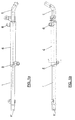
- figures 1a and 1b are two side views of the system for heating oil vapour according to the present invention;
- figure 2 is an example of application of the system on an engine;
- figure 3 is a graph showing the trend in time of the temperatures at different points of the engine and in different configurations.
- In the drawings the same reference numbers and letters are used to indicate the same components.
- In figures 1 a, 1 b and 2 reference1 indicates a conduit (pipe, duct...) which carries oil vapour coming from the engine 2, in particular from a valve 3 that separates the drops of oil from the blow-by vapour coming from inside the engine, and makes said drops pass back into the main circuit in the engine.
- The remaining part of the vapour that is not converted back into oil is conveyed through the
pipe 1 and reintroduced into the air intake circuit of the engine, through the opposite end of the pipe 1', by means of a system that is not illustrated, being of a type known in the prior art, for example by means of a connection to the clean air intake duct of the engine, to be burnt in the combustion process. - The
pipe 1 is covered at least partially by an outer jacket 4, for example consisting of a steel tube, that creates an hollow space closed at the sides around the same pipe, provided with an inlet opening 5 and an outlet opening 6, wherein water coming from the engine cooling system, not illustrated in figure 2, is made to circulate, to produce a heat exchange effect. - The pipe couplings for connection to the cooling circuit are connected to the
openings 5 and 6 in a known way. The water enters through the opening 5 and leaves through theopening 6, returning into the main engine cooling circuit through a point ofintroduction 7 directly into the engine water pump. - The water that is used is preferably water discharged from the heating circuit of the driver's cab, normally consisting of a line branching from the main cooling circuit, before returning to the main circuit in the engine.
- The pipes are preferably made of metal (sheet metal or steel), with good heat conductivity and a low cost. The same applies for the outer jackets.
- The length of the outer jacket 4 is defined according to the specific requirements of the engine on which it is used. The same applies for the diameter and length of the
pipe 1. - Experiments have been carried out that certify the considerable improvement obtained using the system according to this invention.
- Tests were performed in a Cold Tunnel according to the provisions of Standard 7.T1135.
- First a test was performed with the metal pipe without any heating device: with an outside temperature of below -20°C the temperature at which the vapour was introduced into the clean air intake duct for combustion remained below zero continuously for an unlimited time (-6°C with an outside temperature of -21 °C), which is not acceptable;
- Next a test was performed with the metal pipe and heating resistor, using devices known in the prior art: with an outside temperature of below -20°C the temperature at which the vapour was introduced into the clean air intake duct remained below zero continuously for 25 minutes, which may be sufficient for some operating conditions in climates that are not particularly cold, (after 10 minutes a curve of almost zero is postulated with an outside temperature of -17°C / -18°C), but is still not acceptable for cold climates.
- Last of all a test was performed with the metal pipes provided with the system according to the invention: with an outside temperature of below -20°C, the temperature at which the vapour was introduced into the clean air intake duct only remained below zero for 10 minutes. As can be observed in the graph in figure 3, over a period of approximately 50 minutes, the thick continuous line indicates the outside temperature curve (a), almost constant at -20°C; the top dashed line (b) indicates the temperature curve of the oil vapour leaving the engine (valve 3, fig. 2); the dotted line indicates the temperature curve (c) of the water circulating in the chamber 4; the thick dash line indicates the temperature curve (e) of the oil vapour entering the
pipe 1; the fine continuous line indicates the temperature curve (d) of the oil vapour discharged at point 1' and thus at the point at which the vapour enters the clean air duct, which, as can be observed, rises to above zero after 10 minutes. - It will be apparent to the person skilled in the art that other alternative and equivalent embodiments of the invention can be conceived and reduced to practice without departing from the true spirit of the invention.
- For example there may be a plurality of
pipes 1 each equipped with its own outer jacket 4 and connected in the same way to the engine and to the cooling circuit. - The use of the system according to this invention presents some obvious advantages.
- The invention provides advantages in terms of costs, and also energy consumption, since it uses heat that is already available and does not have to be specifically generated, as in the case of heating resistors, allowing the reduction of the battery load. Moreover the system is made more reliable and economical by avoiding the use of heating resistors and the relative wiring.
- By the description set forth above the person skilled in the art is enabled to implement the invention without introducing any further construction details.
Claims (4)
- System for heating the oil vapour flowing through a circuit that is external to a vehicle engine, comprising:- one or more pipes (1) suitable to convey oil vapour coming from the engine (2), and to reintroduce it into the clean air intake circuit of the engine;- one or more outer jackets, suitable to create hollow spaces closed at the sides and fitted around said one or more pipes (1), water, coming from an engine cooling circuit, being made to circulate in said hollow spaces, to produce a heat exchange effect suitable to heat said oil vapour.
- System according to claim 1, characterized in that said one or more outer jackets (4) are connected to a heating circuit of the driver's cab of the vehicle, before reintroduction into the engine cooling circuit.
- System according to claim 1 or 2, characterized in that said one or more pipes (1) and said one or more outer jackets (4) are made of metal.
- Engine of a vehicle, characterized in that it is provided with a system for heating the oil vapour flowing through a circuit that is external to the engine according to any of the previous claims.
Applications Claiming Priority (1)
| Application Number | Priority Date | Filing Date | Title |
|---|---|---|---|
| ITMI20060942 ITMI20060942A1 (en) | 2006-05-12 | 2006-05-12 | HEATING SYSTEM OF OIL VAPORS IN EXTERNAL CIRCULATION AT A VEHICLE ENGINE |
Publications (2)
| Publication Number | Publication Date |
|---|---|
| EP1854968A2 true EP1854968A2 (en) | 2007-11-14 |
| EP1854968A3 EP1854968A3 (en) | 2010-07-28 |
Family
ID=36698909
Family Applications (1)
| Application Number | Title | Priority Date | Filing Date |
|---|---|---|---|
| EP07107838A Ceased EP1854968A3 (en) | 2006-05-12 | 2007-05-09 | System for heating the oil vapour flowing through a circuit that is external to a vehicle engine |
Country Status (5)
| Country | Link |
|---|---|
| EP (1) | EP1854968A3 (en) |
| JP (1) | JP2007303473A (en) |
| CN (1) | CN101070799A (en) |
| IT (1) | ITMI20060942A1 (en) |
| RU (1) | RU2446289C2 (en) |
Cited By (1)
| Publication number | Priority date | Publication date | Assignee | Title |
|---|---|---|---|---|
| WO2025062154A1 (en) * | 2023-09-22 | 2025-03-27 | JCB Research | Internal combustion engine |
Citations (2)
| Publication number | Priority date | Publication date | Assignee | Title |
|---|---|---|---|---|
| US4768493A (en) | 1984-04-27 | 1988-09-06 | Honda Giken Kogyo Kabushiki Kaisha | Blow-by gas heating system for internal combustion engines |
| JP2004204720A (en) * | 2002-12-24 | 2004-07-22 | Suzuki Motor Corp | Blow-by gas recirculation device |
Family Cites Families (7)
| Publication number | Priority date | Publication date | Assignee | Title |
|---|---|---|---|---|
| DE3726332C1 (en) * | 1987-08-07 | 1988-06-23 | Bayerische Motoren Werke Ag | Intake pipe part of an internal combustion engine |
| DE3824791A1 (en) * | 1988-07-21 | 1990-01-25 | Porsche Ag | CRANKCASE VENTILATION |
| RU2052640C1 (en) * | 1992-11-02 | 1996-01-20 | Производственное объединение "Турбомоторный завод" | Device for separating liquid from gas |
| DE4438093C1 (en) * | 1994-10-25 | 1996-03-28 | Continental Ag | Ventilation device for parts of motor vehicle engines |
| JP3282072B2 (en) * | 1997-09-26 | 2002-05-13 | 株式会社クボタ | Engine breather device |
| JP2000274223A (en) * | 1999-03-24 | 2000-10-03 | Kubota Corp | Inlet recirculation type breather device |
| DE102004031499B4 (en) * | 2004-06-30 | 2009-08-13 | Daimler Ag | Crankcase vent line |
-
2006
- 2006-05-12 IT ITMI20060942 patent/ITMI20060942A1/en unknown
-
2007
- 2007-05-09 EP EP07107838A patent/EP1854968A3/en not_active Ceased
- 2007-05-10 CN CNA2007101049693A patent/CN101070799A/en active Pending
- 2007-05-11 RU RU2007117684/06A patent/RU2446289C2/en not_active IP Right Cessation
- 2007-05-14 JP JP2007128082A patent/JP2007303473A/en active Pending
Patent Citations (2)
| Publication number | Priority date | Publication date | Assignee | Title |
|---|---|---|---|---|
| US4768493A (en) | 1984-04-27 | 1988-09-06 | Honda Giken Kogyo Kabushiki Kaisha | Blow-by gas heating system for internal combustion engines |
| JP2004204720A (en) * | 2002-12-24 | 2004-07-22 | Suzuki Motor Corp | Blow-by gas recirculation device |
Cited By (1)
| Publication number | Priority date | Publication date | Assignee | Title |
|---|---|---|---|---|
| WO2025062154A1 (en) * | 2023-09-22 | 2025-03-27 | JCB Research | Internal combustion engine |
Also Published As
| Publication number | Publication date |
|---|---|
| ITMI20060942A1 (en) | 2007-11-13 |
| JP2007303473A (en) | 2007-11-22 |
| CN101070799A (en) | 2007-11-14 |
| RU2446289C2 (en) | 2012-03-27 |
| RU2007117684A (en) | 2008-11-20 |
| EP1854968A3 (en) | 2010-07-28 |
Similar Documents
| Publication | Publication Date | Title |
|---|---|---|
| AU2010224799B2 (en) | Method and apparatus for oiling rotating or oscillating components | |
| US8459024B2 (en) | Turbocharger comprising a cooling device and an oil supply pipe | |
| US6935319B2 (en) | Exhaust-gas recirculation system of an internal combustion engine | |
| RU2449136C1 (en) | Device for internal combustion engine with supercharge | |
| CN104214015B (en) | System and method for heating compressor foreline to reduce condensate formation | |
| US20100186686A1 (en) | Heating systems to prevent freezing of condensation in breather tubes | |
| JP2011518279A (en) | Cooling device for supercharged internal combustion engine | |
| KR20130143704A (en) | Cooling system in a vehicle | |
| US8967096B2 (en) | Condensation device | |
| JP5001465B2 (en) | Cooling device for recirculated exhaust gas in a combustion engine | |
| JP2010511125A (en) | Vehicle cooler device | |
| DE102011053176A1 (en) | Method and device for leak detection of a vehicle lubrication system | |
| CA2878576C (en) | Marine conversion of a diesel engine | |
| CN101946065B (en) | Crank case ventilation | |
| CN101321938B (en) | A cooling system | |
| JP2004204720A (en) | Blow-by gas recirculation device | |
| US8671669B2 (en) | Exhaust gas cooler for a motor vehicle | |
| CN110886646B (en) | Engine cooling system | |
| JP2009108704A (en) | Engine cooling system | |
| RU2446289C2 (en) | System for heating vapors of oil flowing in circuit arranged outside of transport facility engine, and transport facility engine with said system | |
| JP2016135996A (en) | Freezing preventive structure for blow-by gas pipe, internal combustion engine and freezing preventive method for blow-by gas pipe | |
| JP2017190714A (en) | Engine device | |
| EP2662545B1 (en) | Radiant heat discharge arrangement | |
| KR102739171B1 (en) | Apparatus for reducing the temperature of degasing gas | |
| CN109219691B (en) | Engine device |
Legal Events
| Date | Code | Title | Description |
|---|---|---|---|
| PUAI | Public reference made under article 153(3) epc to a published international application that has entered the european phase |
Free format text: ORIGINAL CODE: 0009012 |
|
| AK | Designated contracting states |
Kind code of ref document: A2 Designated state(s): AT BE BG CH CY CZ DE DK EE ES FI FR GB GR HU IE IS IT LI LT LU LV MC MT NL PL PT RO SE SI SK TR |
|
| AX | Request for extension of the european patent |
Extension state: AL BA HR MK YU |
|
| PUAL | Search report despatched |
Free format text: ORIGINAL CODE: 0009013 |
|
| AK | Designated contracting states |
Kind code of ref document: A3 Designated state(s): AT BE BG CH CY CZ DE DK EE ES FI FR GB GR HU IE IS IT LI LT LU LV MC MT NL PL PT RO SE SI SK TR |
|
| AX | Request for extension of the european patent |
Extension state: AL BA HR MK RS |
|
| 17P | Request for examination filed |
Effective date: 20101215 |
|
| AKX | Designation fees paid |
Designated state(s): AT BE BG CH CY CZ DE DK EE ES FI FR GB GR HU IE IS IT LI LT LU LV MC MT NL PL PT RO SE SI SK TR |
|
| 17Q | First examination report despatched |
Effective date: 20110811 |
|
| RAP1 | Party data changed (applicant data changed or rights of an application transferred) |
Owner name: FPT INDUSTRIAL S.P.A. |
|
| STAA | Information on the status of an ep patent application or granted ep patent |
Free format text: STATUS: THE APPLICATION HAS BEEN REFUSED |
|
| 18R | Application refused |
Effective date: 20120713 |