EP1854962A2 - Turbine engine mid-turbine frames - Google Patents
Turbine engine mid-turbine frames Download PDFInfo
- Publication number
- EP1854962A2 EP1854962A2 EP07251904A EP07251904A EP1854962A2 EP 1854962 A2 EP1854962 A2 EP 1854962A2 EP 07251904 A EP07251904 A EP 07251904A EP 07251904 A EP07251904 A EP 07251904A EP 1854962 A2 EP1854962 A2 EP 1854962A2
- Authority
- EP
- European Patent Office
- Prior art keywords
- bearing
- frame
- mid
- load
- turbine
- Prior art date
- Legal status (The legal status is an assumption and is not a legal conclusion. Google has not performed a legal analysis and makes no representation as to the accuracy of the status listed.)
- Granted
Links
- 239000007789 gas Substances 0.000 description 14
- 230000035939 shock Effects 0.000 description 3
- 230000009977 dual effect Effects 0.000 description 2
- 230000000694 effects Effects 0.000 description 2
- 239000000446 fuel Substances 0.000 description 2
- 230000003247 decreasing effect Effects 0.000 description 1
- 230000003993 interaction Effects 0.000 description 1
- 239000003351 stiffener Substances 0.000 description 1
Images


Classifications
-
- F—MECHANICAL ENGINEERING; LIGHTING; HEATING; WEAPONS; BLASTING
- F01—MACHINES OR ENGINES IN GENERAL; ENGINE PLANTS IN GENERAL; STEAM ENGINES
- F01D—NON-POSITIVE DISPLACEMENT MACHINES OR ENGINES, e.g. STEAM TURBINES
- F01D25/00—Component parts, details, or accessories, not provided for in, or of interest apart from, other groups
- F01D25/16—Arrangement of bearings; Supporting or mounting bearings in casings
- F01D25/162—Bearing supports
-
- F—MECHANICAL ENGINEERING; LIGHTING; HEATING; WEAPONS; BLASTING
- F01—MACHINES OR ENGINES IN GENERAL; ENGINE PLANTS IN GENERAL; STEAM ENGINES
- F01D—NON-POSITIVE DISPLACEMENT MACHINES OR ENGINES, e.g. STEAM TURBINES
- F01D25/00—Component parts, details, or accessories, not provided for in, or of interest apart from, other groups
- F01D25/24—Casings; Casing parts, e.g. diaphragms, casing fastenings
-
- F—MECHANICAL ENGINEERING; LIGHTING; HEATING; WEAPONS; BLASTING
- F01—MACHINES OR ENGINES IN GENERAL; ENGINE PLANTS IN GENERAL; STEAM ENGINES
- F01D—NON-POSITIVE DISPLACEMENT MACHINES OR ENGINES, e.g. STEAM TURBINES
- F01D25/00—Component parts, details, or accessories, not provided for in, or of interest apart from, other groups
- F01D25/28—Supporting or mounting arrangements, e.g. for turbine casing
-
- F—MECHANICAL ENGINEERING; LIGHTING; HEATING; WEAPONS; BLASTING
- F05—INDEXING SCHEMES RELATING TO ENGINES OR PUMPS IN VARIOUS SUBCLASSES OF CLASSES F01-F04
- F05D—INDEXING SCHEME FOR ASPECTS RELATING TO NON-POSITIVE-DISPLACEMENT MACHINES OR ENGINES, GAS-TURBINES OR JET-PROPULSION PLANTS
- F05D2250/00—Geometry
- F05D2250/20—Three-dimensional
- F05D2250/22—Three-dimensional parallelepipedal
Definitions
- the present invention generally relates to the field of gas turbine engines.
- the invention relates to a mid-turbine frame for a jet turbine engine.
- Turbofans are a type of gas turbine engine commonly used in aircraft, such as jets.
- the turbofan generally includes a high and a low pressure compressor, a high and a low pressure turbine, a high pressure rotatable shaft, a low pressure rotatable shaft, a fan, and a combuster.
- the high-pressure compressor (HPC) is connected to the high pressure turbine (HPT) by the high pressure rotatable shaft, together acting as a high pressure system.
- the low pressure compressor (LPC) is connected to the low pressure turbine (LPT) by the low pressure rotatable shaft, together acting as a low pressure system.
- the low pressure rotatable shaft is housed within the high pressure shaft and is connected to the fan such that the HPC, HPT, LPC, LPT, and high and low pressure shafts are coaxially aligned.
- bearings are located within the jet turbine engine to help distribute the load created by the high and low pressure systems.
- the bearings are connected to a mid-turbine frame located between the HPT and the LPT by bearing support structures, for example, bearing cones.
- the mid-turbine frame acts to distribute the load on the bearing support structures by transferring the load from the bearing support structures to the engine casing. Decreasing the weight of the mid-turbine frame can significantly increase the efficiency of the jet turbine engine and the jet itself.
- a disclosed mid-turbine frame has a pre-stress design and is connected to an engine casing of a jet turbine engine to distribute a first load from a first bearing and a second load from a second bearing.
- the mid-turbine frame includes at least one torque box, a first bearing, a second bearing, and at least one strut.
- the torque box absorbs the first and second loads from the first and second bearings.
- the first bearing cone connects the first bearing to the torque box and the second bearing cone connects the second bearing to the torque box.
- the strut connects the torque box to the engine casing.
- FIG. 1 shows a representative sectional view of a gas turbine engine 10 about a gas turbine engine axis centerline.
- Gas turbine engine 10 generally includes mid-turbine frame 12, engine casing 14, mounts 16, first bearing 18, and second bearing 20.
- Mid-turbine frame 12 of gas turbine engine 10 has a pre-stress design that allows for expansion of mid-turbine frame 12 upon loading of first and second bearings 18 and 20.
- Mid-turbine frame 12 is housed within engine casing 14 of gas turbine engine 10.
- Mid-turbine frame 12 is connected to first and second bearings 18 and 20 and transfers the load from first and second bearings 18 and 20 to engine casing 14.
- Engine casing 14 protects mid-turbine frame 12 from its surroundings and transfers the loads from mid-turbine frame 12 to mounts 16.
- Mid-turbine frame 12 is designed to have a pre-torque that is independent of any applied load from first and second bearings 18 and 20.
- the pre-torque load is applied to mid-turbine frame 12 during assembly of mid-turbine frame 12 and comes into effect when the loads from first and second bearings 18 and 20 are applied during operation of gas turbine engine 10.
- the applied load from first and second bearings 18 and 20 are canceled by the pre-torque load of mid-turbine frame 12 as the applied load enters mid-turbine frame 12, bringing mid-turbine frame 12 to equilibrium.
- First and second bearings 18 and 20 are located at forward and aft ends of gas turbine engine 10, respectively, below mid-turbine frame 12. First and second bearings 18 and 20 support thrust loads, vertical tension, side gyroscopic loads, as well as vibratory loads from high and low pressure rotors located in gas turbine engine 10. All of the loads supported by first and second bearings 18 and 20 are transferred to engine casing 14 and mounts 16 through mid-turbine frame 12. Second bearing 20 is typically designed to support a greater load than first bearing 18, so mid-turbine frame 12 is designed for stiffness and structural feasibility assuming that second bearing 20 is the extreme situation.
- Mid-turbine frame 12 is a segmented structure with a plurality of segments equally spaced circumferentially within gas turbine engine 10.
- Each segment includes a torque box 22 which is designed to take load from first bearing 18, second bearing 20, and mid-turbine frame 12 and transfer it in a vertical direction toward engine casing 14.
- nine segments are positioned approximately forty degrees apart from one another along the circumference of mid-turbine frame 12.
- twelve total segments are positioned approximately thirty degrees apart from one another along the circumference of mid-turbine frame 12.
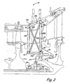
- FIG. 2 shows a schematic view of a first embodiment of mid-turbine frame 12a.
- First and second bearings 18 and 20 are connected to mid-turbine frame 12 by first and second bearing cones 24 and 26, respectively.
- Each of first and second bearing cones 24 and 26 are connected to a bearing arrangement that has an inner rotating race that continuously rotates with high and low pressure rotors and transfer the loads from first and second bearings 18 and 20 to mid-turbine frame 12a.
- Each torque box 22a of mid-turbine frame 12a generally includes first and second vertical pre-stressed rods 28a and 28b; first and second horizontal pre-stressed rods 30a and 30b; and first and second pre-stressed wires 32a and 32b.
- Rods 28a, 28b, 30a, and 30b are connected to each other at approximately ninety-degree angles to form a primary rectangular frame 34.
- Mid-turbine frame 12a is connected to engine casing 14 and mounts 16 at first horizontal rod 30a of primary frame 34.
- rods 28a, 28b, 30a, and 30b had a certain amount of torque applied to them during assembly, rods 28a, 28b, 30a, and 30b of primary frame 34 cancel a portion of the load entering mid-turbine frame 12a from first and second bearings 18 and 20 from first and second bearing cones 24 and 26.
- First and second pre-stressed wires 32a and 32b are connected within primary frame 34 to form an X-shape.
- First wire 32a is connected at a first end 36 proximate the connection of first vertical rod 28a and first horizontal rod 30a and at a second end 38 proximate the connection of second vertical rod 28b and second horizontal rod 30b.
- Second wire 32b is connected at a first end 40 proximate the connection of first vertical rod 28a and second horizontal rod 30b and at a second end 42 proximate the connection of second vertical rod 28b and first horizontal rod 30a.
- First and second wires 32a and 32b act as load fronts or members and absorb any shear load that enters mid-turbine frame 12.
- wires 32a and 32b cancel a portion of the torque from first and second bearings 18 and 20 that enter primary frame 34. Together, rods 28a, 28b, 30a, and 30b and first and second wires 32a and 32b cancel the torque entering mid-turbine frame 12a and equilibrate mid-turbine frame 12a.
- wires 32a and 32b are shear ties.
- FIG. 3 shows a schematic view of a second embodiment of mid-turbine frame 12b.
- a pre-torque is applied to mid-turbine frame 12b to equilibrate any loads from first and second bearings 18 and 20 and thus functions similarly to mid-turbine frame 12a. Similar to FIG. 2, FIG. 3 will be discussed in reference to one segment of mid-turbine frame 12b.
- Each torque box 22b of mid-turbine frame 12b generally includes first and second vertical pre-stressed rods 28a and 28b; first, second, third, and fourth horizontal pre-stressed rods 30a, 30b, 30c, and 30d; and first, second, third, fourth, fifth, and sixth pre-stressed wires 44a, 44b, 44c, 44d, 44e, and 44f.
- Torque box 22b interacts and functions with first and second bearings 18 and 20 and engine casing 14 in the same manner as torque box 22a.
- Rods 28a, 28b, 30a, and 30b of mid-turbine frame 12b connect and function in the same manner as rods 28a, 28b, 30a, and 30b of mid-turbine frame 12a to form primary frame 34.
- Third and fourth horizontal rods 30c and 30d are connected to first and second vertical rods 28a and 28b within primary frame 34 between first and second horizontal rods 30a and 30b.
- First and second wires 44a and 44b are connected between first and second vertical rods 28a and 28b and first and third horizontal rods 30a and 30c to form an X-shape.
- First wire 44a is connected at a first end 46 proximate the connection of first vertical rod 28a and first horizontal rod 30a and at a second end 48 proximate the connection of second vertical 28b and third horizontal rod 30c.
- Second wire 44b is connected at a first end 50 proximate the connection of first vertical rod 28a and third horizontal rod and 30c and at a second end 52 proximate the connection of second vertical rod 28b and first horizontal rod 30a.
- Third and fourth wires 44c and 44d are connected between first and second vertical rods 28a and 28b and third and fourth horizontal rods 30c and 30d to form an X-shape.
- Third wire 44c is connected at a first end 54 proximate the connection of first vertical rod 28a and third horizontal rod 30c and at a second end 56 proximate the connection of second vertical rod 28b and fourth horizontal rod 30c.
- Fourth wire 44d is connected at a first end 58 proximate the connection of first vertical rod 28a and fourth horizontal rod 30d and at a second end 60 proximate the connection of second vertical rod 28b and third horizontal rod 30c.
- Fifth and sixth wires 44e and 44f are connected between first and second vertical rods 28a and 28b and fourth and second horizontal rods 30d and 30b to form an X-shape.
- Fifth wire 44e is connected at a first end 62 proximate the connection of first vertical rod 28a and fourth horizontal rod 30d and at a second end 64 proximate the connection of second vertical rod 28b and second horizontal rod 30b.
- Sixth wire 44f is connected at a first end 66 proximate the connection of first vertical rod 28a and second horizontal rod 30b and at a second end 68 proximate the connection of second vertical rod 28b and fourth horizontal rod 30d.
- FIG. 4 shows a schematic view of a third embodiment of mid-turbine frame 12c.
- a pre-torque is applied to mid-turbine frame 12c to equilibrate any loads from first and second bearings 18 and 20 and thus functions similarly to mid-turbine frame 12a. Similar to FIG. 2, FIG. 4 will be discussed in reference to one segment of mid-turbine frame 12c.
- Each torque box 22c of mid-turbine frame 12c generally includes first, second, third, and fourth vertical pre-stressed rods 70a, 70b, 70c, and 70d; first, second, third, and fourth horizontal pre-stressed rods 30a, 30b, 30c, 30d; and first, second, third, fourth, fifth, and sixth pre-stressed wires 44a, 44b, 44c, 44d, 44e, and 44f.
- Torque box 22c interacts and functions with first and second bearings 18 and 20 and engine casing 14 in the same manner as torque box 22a.
- First and second vertical rods 70a and 70b and first and third horizontal rods 30a and 30c are connected to each other to form a first rectangular frame 72 and third and fourth vertical rods 70c and 70d and fourth and second horizontal rods 30d and 30b are connected to each other at approximately ninety degree angles to form a second rectangular frame 74.
- First and second wires 44a and 44b are connected within first rectangular frame 72 to form an X-shape.
- First wire 44a is connected at a first end 76 proximate the connection of first vertical rod 70a and first horizontal rod 30a and at a second end 78 proximate the connection of second vertical rod 70b and third horizontal rod 30c.
- Second wire 44b is connected at a first end 80 proximate the connection of first vertical rod 70a and third horizontal rod 30c and at a second end 82 proximate the connection of second vertical rod 70b and first horizontal rod 30a.
- Third and fourth wires 44c and 44d are connected between third and fourth horizontal rods 30c and 30d to form an X-shape.
- Third wire 44c is connected at a first end 84 proximate the connection of first vertical rod 70a and third horizontal rod 30c and at a second end 86 proximate the connection of fourth vertical rod 70d and fourth horizontal rod 30d.
- Fourth wire 44f is connected at a first end 88 proximate the connection of third vertical rod 70c and fourth horizontal rod 30d and at a second end 90 proximate the connection of second vertical rod 70b and third horizontal rod 30c.
- Fifth and sixth wires 44e and 44f are connected within second rectangular frame 74 to form an X-shape.
- Fifth wire 44e is connected at a first end 92 proximate the connection of third vertical rod 70c and fourth horizontal rod 30d and at a second end 94 proximate the connection of fourth vertical rod 70d and second horizontal rod 30b.
- Sixth wire 44d is connected at a first end 96 proximate the connection of third vertical rod 70c and second horizontal rod 30b and at a second end 98 proximate the connection of fourth vertical rod 70d and fourth horizontal rod 30d.
- FIG. 5 shows a schematic view of a fourth embodiment of mid-turbine frame 12d. Similar to FIG. 2, FIG. 5 will be discussed in reference to one segment of mid-turbine frame 12d.
- Each segment of mid-turbine frame 12d generally includes frame 100, first bearing cone 102, and second bearing cone 104.
- Frame 100 of mid-turbine frame 12d functions to transfer the loads from first and second bearing cones 102 and 104 and as primary torque box 106.
- Mid-turbine frame 12d also has an additional dual torque box design with first and second bearing cones 102 and 104 functioning as secondary torque boxes.
- the secondary torque boxes are divided into two parts with first bearing cone 102 taking the load from first bearing 18 and second bearing cone 104 taking the load from second bearing 20.
- the loads from first bearing 18 are thus transferred to first bearing cone 102 and the loads from second bearing 20 are thus transferred to second bearing cone 104.
- First and second bearing cones 102 and 104 take the loads from first and second bearings 18 and 20, respectively, and convert the loads to torque, which are subsequently canceled at frame 100 prior to reaching engine casing 14.
- Torque boxes 102, 104, and 106 interact with each other to balance any load imbalance from first and second bearings 18 and 20.
- FIG. 6 shows a schematic view of a fifth embodiment of mid-turbine frame 12e. Similar to FIG. 2, FIG. 6 will be discussed in reference to one segment of mid-turbine frame 12e.
- Each segment of mid-turbine frame 12e generally includes first bearing cone 200, second bearing cone 202, torque converter 204, spring 206, oleo strut 208, and frame 210.
- First and second bearings 18 and 20 are connected to first and second bearing cones 200 and 202, respectively, which are attached to torque converter 204 and spring 206.
- the loads from first and second bearings 18 and 20 are equilibrated at torque converter 204 and spring 206 and are subsequently transmitted to frame 210 through oleo strut 208.
- Frame 210 connects first and second bearings 18 and 20 to engine casing 14 and mounts 16.
- first and second bearings 18 and 20 travel through first and second bearing cones 200 and 202, respectively, where they meet at torque converter 204, which is formed by the interconnection of first bearing cone 200, second bearing cone 202, and spring 206.
- Torque converter 204 allows first and second bearing cones 200 and 202 to shift by becoming slack upon load imbalances from first and second bearings 18 and 20.
- Spring 206 allows the torques from first and second bearing cones 200 and 202 to be balanced such that torque converter 204 cancels all the torques before entering oleo strut 208. This mechanism allows load imbalances caused by eccentric loading or shocks to be easily equilibrated.
- oleo strut 208 extends to equilibrate the load from torque converter 204.
- Oleo strut 208 functions similarly to an elastic band, actuating and deflecting as necessary to help equilibrate any load imbalance from first and second bearings 18 and 20.
- the eccentric torque from torque converter 204 is then transferred to frame 210, which functions to transfer the loads from first and second bearings 18 and 20 to engine casing 14.
- the torque transfer from first and second bearings 18 and 20 thus occurs through the interaction of torque converter 204, oleo strut 206, and frame 210 and torque converter 204 and frame 210 cancel the torques from first and second bearings 18 and 20.
- FIG. 7 shows a schematic view of a sixth embodiment of mid-turbine frame 12f. Similar to FIG. 2, FIG. 7 will be discussed in reference to one segment of mid-turbine frame 12f.
- Each segment of mid-turbine frame 12f generally includes first bearing cone 300, second bearing cone 302, integrated torque box 304, first, second, and third oleo struts 306a, 306b, and 306c (collectively, oleo struts 306), and stiffened strut 308.
- First and second bearings 18 and 20 are connected to engine casing 14 through first and second bearing cones 300 and 302, respectively.
- First and second bearing cones 300 and 302 are then connected to stiffened strut 308 by oleo struts 306.
- Integrated torque box 304 includes the connections of first and second bearing cones 300 and 302 to oleo struts 306. Similar to torque converter 204 of mid-turbine frame 12e, integrated torque box 304 of mid-turbine frame 12f equilibrates the loads from first and second bearing cones 300 and 302. When there is a load imbalance from the loads coming from first and second bearings 18 and 20, integrated torque box 304 equilibrates the loads before the loads are transferred to stiffened strut 308.
- First and second bearing cones 300 and 302 are connected to stiffened strut 308 by oleo struts 306.
- First bearing cone 300 is attached to first and second oleo struts 306a and 306b and second bearing cone 302 is attached to first and third oleo struts 306a and 306c.
- Oleo struts 306 of mid-turbine frame 12f act as elastic bands and allow first and second bearing cones 300 and 302 to shift due to eccentric loading or shock.
- oleo struts 306 extend and compensate for the load imbalance, bringing mid-turbine frame 12f back to equilibrium prior to transferring the loads to stiffened strut 308.
- Stiffened strut 308 generally includes first and second vertical pre-stressed rods 310a and 310b, vertical rod 312 attached to engine casing 14, and first and second pre-stressed wires 314a and 314b.
- First and second vertical rods 310a and 310b are connected between vertical rod 312 and first oleo strut 306a, forming frame 316.
- First and second wires 314a and 314b are positioned within frame 316 to form an X-shape.
- First and second wires 314a and 314b are positioned within frame 316 to act as stiffeners for stiffened strut 308 and to prevent first and second rods 310a and 310b from collapsing on each other.
- First and second wires 314a and 314b also transfer the shear loads from first and second bearings 18 and 20, if any, to first and second rods 310a and 310b and utilizes them by balancing them either at the top or the bottom of first and second rods 310a and 310b.
- First and second wires 314a and 314b thus perform a structural as well as a load transfer function.
- first and second wires 314a and 314b are shear ties.
- the mid-turbine frame of the present invention transfers the loads from a first bearing and a second bearing to an engine casing surrounding the mid-turbine frame.
- the mid-turbine frame has a pre-stress design that includes a plurality of pre-stressed rods and wires that cancel any applied load from the first and second bearings.
- the pre-torque design of the first embodiment of the mid-turbine frame is independent of any applied load from the first and second bearings and comes into effect when the loads from the first and second bearings are applied during operation of the gas turbine engine.
- the applied loads from the first and second bearings are canceled by the pre-torque load of the mid-turbine frame as the applied loads enter the mid-turbine frame, bringing the mid-turbine frame to equilibrium.
- the mid-turbine frame includes various torque box designs.
- the torque box designs include a dual torque box design, a torque converter, and an integrated torque box.
- the second embodiment of the mid-turbine frame allows for the expansion of a first bearing cone and a second bearing cone that connect the first bearing and second bearing to the torque box.
- the torque box designs allow for the expansion of the mid-turbine frame to counteract any eccentric loading or shocks by compensating for any load imbalances from the first and second bearings.
Landscapes
- Engineering & Computer Science (AREA)
- Mechanical Engineering (AREA)
- General Engineering & Computer Science (AREA)
- Turbine Rotor Nozzle Sealing (AREA)
Abstract
Description
- The present invention generally relates to the field of gas turbine engines. In particular, the invention relates to a mid-turbine frame for a jet turbine engine.
- Turbofans are a type of gas turbine engine commonly used in aircraft, such as jets. The turbofan generally includes a high and a low pressure compressor, a high and a low pressure turbine, a high pressure rotatable shaft, a low pressure rotatable shaft, a fan, and a combuster. The high-pressure compressor (HPC) is connected to the high pressure turbine (HPT) by the high pressure rotatable shaft, together acting as a high pressure system. Likewise, the low pressure compressor (LPC) is connected to the low pressure turbine (LPT) by the low pressure rotatable shaft, together acting as a low pressure system. The low pressure rotatable shaft is housed within the high pressure shaft and is connected to the fan such that the HPC, HPT, LPC, LPT, and high and low pressure shafts are coaxially aligned.
- Outside air is drawn into the jet turbine engine by the fan and the HPC, which increases the pressure of the air drawn into the system. The high-pressure air then enters the combuster, which burns fuel and emits the exhaust gases. The HPT directly drives the HPC using the fuel by rotating the high pressure shaft. The LPT uses the exhaust generated in the combuster to turn the low pressure shaft, which powers the fan to continually bring air into the system. The air brought in by the fan bypasses the HPT and LPT and acts to increase the engine's thrust, driving the jet forward.
- In order to support the high and low pressure systems, bearings are located within the jet turbine engine to help distribute the load created by the high and low pressure systems. The bearings are connected to a mid-turbine frame located between the HPT and the LPT by bearing support structures, for example, bearing cones. The mid-turbine frame acts to distribute the load on the bearing support structures by transferring the load from the bearing support structures to the engine casing. Decreasing the weight of the mid-turbine frame can significantly increase the efficiency of the jet turbine engine and the jet itself.
- A disclosed mid-turbine frame has a pre-stress design and is connected to an engine casing of a jet turbine engine to distribute a first load from a first bearing and a second load from a second bearing. The mid-turbine frame includes at least one torque box, a first bearing, a second bearing, and at least one strut. The torque box absorbs the first and second loads from the first and second bearings. The first bearing cone connects the first bearing to the torque box and the second bearing cone connects the second bearing to the torque box. The strut connects the torque box to the engine casing.
-
- FIG. 1 is a representative sectional view of a gas turbine engine.
- FIG. 2 is a schematic view of a first embodiment of the mid-turbine frame.
- FIG. 3 is a schematic view of a second embodiment of the mid-turbine frame.
- FIG. 4 is a schematic view of a third embodiment of the mid-turbine frame.
- FIG. 5 is a schematic view of a fourth embodiment of the mid-turbine frame.
- FIG. 6 is a schematic view of a fifth embodiment of the mid-turbine frame.
- FIG. 7 is a schematic view of a sixth embodiment of the mid-turbine frame.
- FIG. 1 shows a representative sectional view of a
gas turbine engine 10 about a gas turbine engine axis centerline.Gas turbine engine 10 generally includesmid-turbine frame 12,engine casing 14,mounts 16, first bearing 18, and second bearing 20.Mid-turbine frame 12 ofgas turbine engine 10 has a pre-stress design that allows for expansion ofmid-turbine frame 12 upon loading of first andsecond bearings - Mid-turbine
frame 12 is housed withinengine casing 14 ofgas turbine engine 10.Mid-turbine frame 12 is connected to first andsecond bearings second bearings engine casing 14.Engine casing 14 protectsmid-turbine frame 12 from its surroundings and transfers the loads frommid-turbine frame 12 tomounts 16. Mid-turbineframe 12 is designed to have a pre-torque that is independent of any applied load from first andsecond bearings mid-turbine frame 12 during assembly ofmid-turbine frame 12 and comes into effect when the loads from first andsecond bearings gas turbine engine 10. The applied load from first andsecond bearings mid-turbine frame 12 as the applied load entersmid-turbine frame 12, bringingmid-turbine frame 12 to equilibrium. - First and
second bearings gas turbine engine 10, respectively, belowmid-turbine frame 12. First andsecond bearings gas turbine engine 10. All of the loads supported by first andsecond bearings engine casing 14 and mounts 16 throughmid-turbine frame 12. Second bearing 20 is typically designed to support a greater load than first bearing 18, somid-turbine frame 12 is designed for stiffness and structural feasibility assuming that second bearing 20 is the extreme situation. -
Mid-turbine frame 12 is a segmented structure with a plurality of segments equally spaced circumferentially withingas turbine engine 10. Each segment includes a torque box 22 which is designed to take load from first bearing 18, second bearing 20, andmid-turbine frame 12 and transfer it in a vertical direction towardengine casing 14. In one embodiment, nine segments are positioned approximately forty degrees apart from one another along the circumference ofmid-turbine frame 12. In another embodiment, twelve total segments are positioned approximately thirty degrees apart from one another along the circumference ofmid-turbine frame 12. - FIG. 2 shows a schematic view of a first embodiment of
mid-turbine frame 12a. For ease of discussion, FIG. 2 will be discussed in reference to one segment ofmid-turbine frame 12a. First andsecond bearings mid-turbine frame 12 by first andsecond bearing cones second bearing cones second bearings mid-turbine frame 12a. - Each
torque box 22a ofmid-turbine frame 12a generally includes first and second vertical pre-stressedrods rods pre-stressed wires Rods rectangular frame 34.Mid-turbine frame 12a is connected toengine casing 14 andmounts 16 at firsthorizontal rod 30a ofprimary frame 34. Becauserods rods primary frame 34 cancel a portion of the load enteringmid-turbine frame 12a from first andsecond bearings second bearing cones - First and second
pre-stressed wires primary frame 34 to form an X-shape.First wire 32a is connected at afirst end 36 proximate the connection of firstvertical rod 28a and firsthorizontal rod 30a and at asecond end 38 proximate the connection of secondvertical rod 28b and secondhorizontal rod 30b.Second wire 32b is connected at afirst end 40 proximate the connection of firstvertical rod 28a and secondhorizontal rod 30b and at a second end 42 proximate the connection of secondvertical rod 28b and firsthorizontal rod 30a. First andsecond wires mid-turbine frame 12. Similar torods wires wires second bearings primary frame 34. Together, rods 28a, 28b, 30a, and 30b and first andsecond wires mid-turbine frame 12a and equilibratemid-turbine frame 12a. In one embodiment,wires - FIG. 3 shows a schematic view of a second embodiment of
mid-turbine frame 12b. During assembly, a pre-torque is applied tomid-turbine frame 12b to equilibrate any loads from first andsecond bearings mid-turbine frame 12a. Similar to FIG. 2, FIG. 3 will be discussed in reference to one segment ofmid-turbine frame 12b. Eachtorque box 22b ofmid-turbine frame 12b generally includes first and second verticalpre-stressed rods pre-stressed rods pre-stressed wires Torque box 22b interacts and functions with first andsecond bearings engine casing 14 in the same manner astorque box 22a.Rods mid-turbine frame 12b connect and function in the same manner asrods mid-turbine frame 12a to formprimary frame 34. Third and fourthhorizontal rods vertical rods primary frame 34 between first and secondhorizontal rods - First and
second wires vertical rods horizontal rods First wire 44a is connected at afirst end 46 proximate the connection of firstvertical rod 28a and firsthorizontal rod 30a and at asecond end 48 proximate the connection of second vertical 28b and thirdhorizontal rod 30c.Second wire 44b is connected at afirst end 50 proximate the connection of firstvertical rod 28a and third horizontal rod and 30c and at a second end 52 proximate the connection of secondvertical rod 28b and firsthorizontal rod 30a. - Third and
fourth wires vertical rods horizontal rods Third wire 44c is connected at afirst end 54 proximate the connection of firstvertical rod 28a and thirdhorizontal rod 30c and at asecond end 56 proximate the connection of secondvertical rod 28b and fourthhorizontal rod 30c.Fourth wire 44d is connected at afirst end 58 proximate the connection of firstvertical rod 28a and fourthhorizontal rod 30d and at asecond end 60 proximate the connection of secondvertical rod 28b and thirdhorizontal rod 30c. - Fifth and
sixth wires 44e and 44f are connected between first and secondvertical rods horizontal rods Fifth wire 44e is connected at afirst end 62 proximate the connection of firstvertical rod 28a and fourthhorizontal rod 30d and at asecond end 64 proximate the connection of secondvertical rod 28b and secondhorizontal rod 30b. Sixth wire 44f is connected at afirst end 66 proximate the connection of firstvertical rod 28a and secondhorizontal rod 30b and at a second end 68 proximate the connection of secondvertical rod 28b and fourthhorizontal rod 30d. - FIG. 4 shows a schematic view of a third embodiment of
mid-turbine frame 12c. During assembly, a pre-torque is applied tomid-turbine frame 12c to equilibrate any loads from first andsecond bearings mid-turbine frame 12a. Similar to FIG. 2, FIG. 4 will be discussed in reference to one segment ofmid-turbine frame 12c. Eachtorque box 22c ofmid-turbine frame 12c generally includes first, second, third, and fourth verticalpre-stressed rods pre-stressed rods pre-stressed wires Torque box 22c interacts and functions with first andsecond bearings engine casing 14 in the same manner astorque box 22a. First and secondvertical rods horizontal rods rectangular frame 72 and third and fourthvertical rods horizontal rods rectangular frame 74. - First and
second wires rectangular frame 72 to form an X-shape.First wire 44a is connected at afirst end 76 proximate the connection of firstvertical rod 70a and firsthorizontal rod 30a and at asecond end 78 proximate the connection of secondvertical rod 70b and thirdhorizontal rod 30c.Second wire 44b is connected at afirst end 80 proximate the connection of firstvertical rod 70a and thirdhorizontal rod 30c and at asecond end 82 proximate the connection of secondvertical rod 70b and firsthorizontal rod 30a. - Third and
fourth wires horizontal rods Third wire 44c is connected at afirst end 84 proximate the connection of firstvertical rod 70a and thirdhorizontal rod 30c and at asecond end 86 proximate the connection of fourthvertical rod 70d and fourthhorizontal rod 30d. Fourth wire 44f is connected at afirst end 88 proximate the connection of thirdvertical rod 70c and fourthhorizontal rod 30d and at asecond end 90 proximate the connection of secondvertical rod 70b and thirdhorizontal rod 30c. - Fifth and
sixth wires 44e and 44f are connected within secondrectangular frame 74 to form an X-shape.Fifth wire 44e is connected at afirst end 92 proximate the connection of thirdvertical rod 70c and fourthhorizontal rod 30d and at asecond end 94 proximate the connection of fourthvertical rod 70d and secondhorizontal rod 30b.Sixth wire 44d is connected at afirst end 96 proximate the connection of thirdvertical rod 70c and secondhorizontal rod 30b and at asecond end 98 proximate the connection of fourthvertical rod 70d and fourthhorizontal rod 30d. - FIG. 5 shows a schematic view of a fourth embodiment of
mid-turbine frame 12d. Similar to FIG. 2, FIG. 5 will be discussed in reference to one segment ofmid-turbine frame 12d. Each segment ofmid-turbine frame 12d generally includesframe 100,first bearing cone 102, andsecond bearing cone 104.Frame 100 ofmid-turbine frame 12d functions to transfer the loads from first andsecond bearing cones primary torque box 106.Mid-turbine frame 12d also has an additional dual torque box design with first andsecond bearing cones - The secondary torque boxes are divided into two parts with
first bearing cone 102 taking the load fromfirst bearing 18 andsecond bearing cone 104 taking the load fromsecond bearing 20. The loads fromfirst bearing 18 are thus transferred tofirst bearing cone 102 and the loads fromsecond bearing 20 are thus transferred tosecond bearing cone 104. First andsecond bearing cones second bearings frame 100 prior to reachingengine casing 14.Torque boxes second bearings - FIG. 6 shows a schematic view of a fifth embodiment of
mid-turbine frame 12e. Similar to FIG. 2, FIG. 6 will be discussed in reference to one segment ofmid-turbine frame 12e. Each segment ofmid-turbine frame 12e generally includesfirst bearing cone 200,second bearing cone 202,torque converter 204,spring 206,oleo strut 208, andframe 210. First andsecond bearings second bearing cones torque converter 204 andspring 206. The loads from first andsecond bearings torque converter 204 andspring 206 and are subsequently transmitted to frame 210 througholeo strut 208.Frame 210 connects first andsecond bearings engine casing 14 and mounts 16. - The loads from first and
second bearings second bearing cones torque converter 204, which is formed by the interconnection offirst bearing cone 200,second bearing cone 202, andspring 206.Torque converter 204 allows first andsecond bearing cones second bearings Spring 206 allows the torques from first andsecond bearing cones torque converter 204 cancels all the torques before enteringoleo strut 208. This mechanism allows load imbalances caused by eccentric loading or shocks to be easily equilibrated. - When
first bearing cone 200 orsecond bearing cone 202 shifts,oleo strut 208 extends to equilibrate the load fromtorque converter 204. Oleo strut 208 functions similarly to an elastic band, actuating and deflecting as necessary to help equilibrate any load imbalance from first andsecond bearings torque converter 204 is then transferred to frame 210, which functions to transfer the loads from first andsecond bearings engine casing 14. The torque transfer from first andsecond bearings torque converter 204,oleo strut 206, andframe 210 andtorque converter 204 andframe 210 cancel the torques from first andsecond bearings - FIG. 7 shows a schematic view of a sixth embodiment of
mid-turbine frame 12f. Similar to FIG. 2, FIG. 7 will be discussed in reference to one segment ofmid-turbine frame 12f. Each segment ofmid-turbine frame 12f generally includesfirst bearing cone 300,second bearing cone 302,integrated torque box 304, first, second, and third oleo struts 306a, 306b, and 306c (collectively, oleo struts 306), and stiffenedstrut 308. First andsecond bearings engine casing 14 through first andsecond bearing cones second bearing cones strut 308 by oleo struts 306. -
Integrated torque box 304 includes the connections of first andsecond bearing cones torque converter 204 ofmid-turbine frame 12e,integrated torque box 304 ofmid-turbine frame 12f equilibrates the loads from first andsecond bearing cones second bearings integrated torque box 304 equilibrates the loads before the loads are transferred to stiffenedstrut 308. - First and
second bearing cones strut 308 by oleo struts 306. First bearingcone 300 is attached to first and second oleo struts 306a and 306b andsecond bearing cone 302 is attached to first and third oleo struts 306a and 306c. Oleo struts 306 ofmid-turbine frame 12f act as elastic bands and allow first andsecond bearing cones second bearing cones mid-turbine frame 12f back to equilibrium prior to transferring the loads to stiffenedstrut 308. -
Stiffened strut 308 generally includes first and second verticalpre-stressed rods vertical rod 312 attached toengine casing 14, and first and secondpre-stressed wires vertical rods vertical rod 312 andfirst oleo strut 306a, formingframe 316. First andsecond wires frame 316 to form an X-shape. First andsecond wires frame 316 to act as stiffeners for stiffenedstrut 308 and to prevent first andsecond rods second wires second bearings second rods second rods second wires second wires - The mid-turbine frame of the present invention transfers the loads from a first bearing and a second bearing to an engine casing surrounding the mid-turbine frame. In a first set of configurations as illustrated in FIGS. 2-4, the mid-turbine frame has a pre-stress design that includes a plurality of pre-stressed rods and wires that cancel any applied load from the first and second bearings. The pre-torque design of the first embodiment of the mid-turbine frame is independent of any applied load from the first and second bearings and comes into effect when the loads from the first and second bearings are applied during operation of the gas turbine engine. The applied loads from the first and second bearings are canceled by the pre-torque load of the mid-turbine frame as the applied loads enter the mid-turbine frame, bringing the mid-turbine frame to equilibrium.
- In a second set of configurations as illustrated in FIGS. 5-7, the mid-turbine frame includes various torque box designs. The torque box designs include a dual torque box design, a torque converter, and an integrated torque box. The second embodiment of the mid-turbine frame allows for the expansion of a first bearing cone and a second bearing cone that connect the first bearing and second bearing to the torque box. The torque box designs allow for the expansion of the mid-turbine frame to counteract any eccentric loading or shocks by compensating for any load imbalances from the first and second bearings.
- Although the present invention has been described with reference to preferred embodiments, workers skilled in the art will recognize that changes may be made in form and detail without departing from the scope of the invention.
Claims (21)
- A mid-turbine frame (12) having an expandable design connected to an engine casing of a jet turbine engine for compensating a first load from a first bearing (18) and a second load from a second bearing (20), the mid-turbine frame comprising:at least one torque box (22) for absorbing the first and second loads;a first bearing cone (24) connecting the first bearing (18) to the torque box;a second bearing cone (26) connecting the second bearing (20) to the torque box; andat least one strut connecting the torque box (22) to the engine casing (14).
- The mid-turbine frame of claim 1, and further comprising a plurality of torque boxes and a plurality of struts.
- The mid-turbine frame of claim 1, wherein the torque box (22) comprises:a plurality of pre-stressed support rods (30; 70); anda plurality of pre-stressed support wires (32; 44) positioned within the plurality of pre-stressed support rods (30; 70).
- The mid-turbine frame of claim 1, wherein the torque box comprises:a portion of the first bearing cone (200);a portion of the second bearing cone (202);an oleo strut (208) connected to the first and second bearing cones (200; 202); anda spring (206) connected between the first and second bearing cones (200; 202).
- The mid-turbine frame of claim 1, wherein the torque box comprises:a portion of the first bearing cone (300);a portion of the second bearing cone (302); anda plurality of oleo struts (306) connected to the first and second bearing cones (300; 302).
- An expandable support frame connected to at least one mount of a gas turbine engine for transferring a first load from a first bearing (18) and a second load from a second bearing (20) to the mount, the mid-turbine frame comprising:a plurality of pre-stressed supports for equilibrating the first and second loads.
- The support frame of claim 6, wherein each of the pre-stressed supports comprises:a plurality of pre-stressed rods (30; 70) positioned to form at least one frame (34; 72; 74); anda plurality of pre-stressed wires (32; 44) positioned within the frame.
- The support frame of claim 7, wherein the pre-stressed wires (32; 44) are shear ties.
- The support frame of claim 6, 7 or 8, wherein the first load from the first bearing (18) is transferred to the gas turbine engine through a first bearing cone (24; 200; 300) and wherein the second load from the second bearing (20) is transferred to the gas turbine engine through a second bearing cone (26; 202; 302).
- The support frame of claim 9, and further comprising at least one oleo strut (208; 306) connected to the first and second bearing cones (26; 202; 302).
- The support frame of claim 9, and further comprising a torque box (210) positioned between the first and second bearing cones (200; 202) and the engine casing (14).
- The support frame of any of claims 6 to 11, wherein the plurality of pre-stressed supports (32; 44) expand to compensate for load imbalances from the first and second bearings (18; 20).
- A support structure connectable to a gas turbine engine for transferring a first load from a first bearing (18) and a second load from a second bearing (20) to an engine casing (14) of the gas turbine engine, the support structure comprising:a frame (34; 72; 74; 210) connecting the first and second bearings (18; 20) to the engine casing; andexpansion means connected to the frame for absorbing the first and second loads.
- The support structure of claim 13, wherein the frame comprises a plurality of pre-stressed rods (30; 70).
- The support structure of claim 14, wherein the expansion means comprises:a plurality of pre-stressed wires (32; 44) positioned between the plurality of pre-stressed rods (30; 70) to form an X-shape.
- The support structure of claim 13, wherein the expansion means comprises at least one oleo strut (208; 306).
- The support structure of claim 16, wherein the oleo strut (208) is positioned between the frame (210) and the first and second bearings (18; 20).
- The support structure of claim 13, and further comprising a torque converter (204), wherein the torque converter (204) comprises:a first bearing cone (200) connected between the first bearing (18) and the frame (210);a second bearing cone (202) connected between the second bearing (20) and the frame (210);an oleo strut (208) connected to the first and second bearing cones (200; 202); anda spring (206) connected between the first and second bearing cones (200; 202).
- The support structure of claim 13, and further comprising an integrated torque box (304), wherein the integrated torque box (304) comprises:a first bearing cone (300) connected between the first bearing (18) and the frame;a second bearing cone (302) connected between the second bearing (20) and the frame;a plurality of oleo struts (306) connected to the first and second bearing cones (200; 202).
- The support structure of claim 13, and further comprising a torque box for equilibrating a load imbalance from the first and second bearings (18; 20).
- A mid-turbine frame (12) having an expandable design connected to an engine casing of a jet turbine engine for compensating a first load from a first bearing (18) and a second load from a second bearing (20), the mid-turbine frame comprising:at least one torque box (22) for absorbing the first and second loads;a first bearing cone (24) connecting the first bearing (18) to the torque box; anda second bearing cone (26) connecting the second bearing (20) to the torque box.
Applications Claiming Priority (1)
| Application Number | Priority Date | Filing Date | Title |
|---|---|---|---|
| US11/430,626 US7610763B2 (en) | 2006-05-09 | 2006-05-09 | Tailorable design configuration topologies for aircraft engine mid-turbine frames |
Publications (3)
| Publication Number | Publication Date |
|---|---|
| EP1854962A2 true EP1854962A2 (en) | 2007-11-14 |
| EP1854962A3 EP1854962A3 (en) | 2011-03-02 |
| EP1854962B1 EP1854962B1 (en) | 2013-08-14 |
Family
ID=38283035
Family Applications (1)
| Application Number | Title | Priority Date | Filing Date |
|---|---|---|---|
| EP07251904.4A Expired - Fee Related EP1854962B1 (en) | 2006-05-09 | 2007-05-08 | Turbine engine mid-turbine frames |
Country Status (3)
| Country | Link |
|---|---|
| US (2) | US7610763B2 (en) |
| EP (1) | EP1854962B1 (en) |
| JP (1) | JP2007303465A (en) |
Cited By (4)
| Publication number | Priority date | Publication date | Assignee | Title |
|---|---|---|---|---|
| EP2148046A2 (en) | 2008-07-23 | 2010-01-27 | United Technologies Corporation | Actuated variable geometry mid turbine frame design |
| EP2192276A2 (en) * | 2008-11-28 | 2010-06-02 | Pratt & Whitney Canada Corp. | Mid turbine frame system for gas turbine engine |
| EP2192275A3 (en) * | 2008-11-28 | 2013-01-02 | Pratt & Whitney Canada Corp. | Mid turbine frame system for gas turbine engine |
| EP3315733A1 (en) * | 2016-10-26 | 2018-05-02 | MTU Aero Engines GmbH | Intermediate turbine housing for a gas turbine |
Families Citing this family (36)
| Publication number | Priority date | Publication date | Assignee | Title |
|---|---|---|---|---|
| US7594405B2 (en) * | 2006-07-27 | 2009-09-29 | United Technologies Corporation | Catenary mid-turbine frame design |
| US7797946B2 (en) * | 2006-12-06 | 2010-09-21 | United Technologies Corporation | Double U design for mid-turbine frame struts |
| US8128021B2 (en) | 2008-06-02 | 2012-03-06 | United Technologies Corporation | Engine mount system for a turbofan gas turbine engine |
| US20140174056A1 (en) | 2008-06-02 | 2014-06-26 | United Technologies Corporation | Gas turbine engine with low stage count low pressure turbine |
| US8061980B2 (en) * | 2008-08-18 | 2011-11-22 | United Technologies Corporation | Separation-resistant inlet duct for mid-turbine frames |
| EP2184445A1 (en) * | 2008-11-05 | 2010-05-12 | Siemens Aktiengesellschaft | Axial segmented vane support for a gas turbine |
| US8347500B2 (en) * | 2008-11-28 | 2013-01-08 | Pratt & Whitney Canada Corp. | Method of assembly and disassembly of a gas turbine mid turbine frame |
| US8099962B2 (en) * | 2008-11-28 | 2012-01-24 | Pratt & Whitney Canada Corp. | Mid turbine frame system and radial locator for radially centering a bearing for gas turbine engine |
| US8347635B2 (en) * | 2008-11-28 | 2013-01-08 | Pratt & Whitey Canada Corp. | Locking apparatus for a radial locator for gas turbine engine mid turbine frame |
| US20100132377A1 (en) * | 2008-11-28 | 2010-06-03 | Pratt & Whitney Canada Corp. | Fabricated itd-strut and vane ring for gas turbine engine |
| US20100132371A1 (en) * | 2008-11-28 | 2010-06-03 | Pratt & Whitney Canada Corp. | Mid turbine frame system for gas turbine engine |
| US8091371B2 (en) * | 2008-11-28 | 2012-01-10 | Pratt & Whitney Canada Corp. | Mid turbine frame for gas turbine engine |
| US8182204B2 (en) * | 2009-04-24 | 2012-05-22 | Pratt & Whitney Canada Corp. | Deflector for a gas turbine strut and vane assembly |
| US9284887B2 (en) | 2009-12-31 | 2016-03-15 | Rolls-Royce North American Technologies, Inc. | Gas turbine engine and frame |
| WO2011129724A1 (en) * | 2010-04-16 | 2011-10-20 | Volvo Aero Corporation | A strut, a gas turbine engine frame comprising the strut and a gas turbine engine comprising the frame |
| US9631558B2 (en) | 2012-01-03 | 2017-04-25 | United Technologies Corporation | Geared architecture for high speed and small volume fan drive turbine |
| US9239012B2 (en) | 2011-06-08 | 2016-01-19 | United Technologies Corporation | Flexible support structure for a geared architecture gas turbine engine |
| US9896966B2 (en) | 2011-08-29 | 2018-02-20 | United Technologies Corporation | Tie rod for a gas turbine engine |
| US8979484B2 (en) | 2012-01-05 | 2015-03-17 | Pratt & Whitney Canada Corp. | Casing for an aircraft turbofan bypass engine |
| US20130340435A1 (en) * | 2012-01-31 | 2013-12-26 | Gregory M. Savela | Gas turbine engine aft spool bearing arrangement and hub wall configuration |
| US9476320B2 (en) | 2012-01-31 | 2016-10-25 | United Technologies Corporation | Gas turbine engine aft bearing arrangement |
| US9555871B2 (en) * | 2012-03-05 | 2017-01-31 | The Boeing Company | Two-surface sandwich structure for accommodating in-plane expansion of one of the surfaces relative to the opposing surface |
| US8756908B2 (en) | 2012-05-31 | 2014-06-24 | United Technologies Corporation | Fundamental gear system architecture |
| US8572943B1 (en) | 2012-05-31 | 2013-11-05 | United Technologies Corporation | Fundamental gear system architecture |
| US20150308351A1 (en) | 2012-05-31 | 2015-10-29 | United Technologies Corporation | Fundamental gear system architecture |
| US9217371B2 (en) | 2012-07-13 | 2015-12-22 | United Technologies Corporation | Mid-turbine frame with tensioned spokes |
| US9222413B2 (en) | 2012-07-13 | 2015-12-29 | United Technologies Corporation | Mid-turbine frame with threaded spokes |
| US9587514B2 (en) | 2012-07-13 | 2017-03-07 | United Technologies Corporation | Vane insertable tie rods with keyed connections |
| US9410441B2 (en) | 2012-09-13 | 2016-08-09 | Pratt & Whitney Canada Corp. | Turboprop engine with compressor turbine shroud |
| US10060291B2 (en) | 2013-03-05 | 2018-08-28 | United Technologies Corporation | Mid-turbine frame rod and turbine case flange |
| GB201418396D0 (en) * | 2014-10-17 | 2014-12-03 | Rolls Royce Plc | Gas turbine engine support structures |
| US10443449B2 (en) | 2015-07-24 | 2019-10-15 | Pratt & Whitney Canada Corp. | Spoke mounting arrangement |
| US10247035B2 (en) | 2015-07-24 | 2019-04-02 | Pratt & Whitney Canada Corp. | Spoke locking architecture |
| US10914193B2 (en) | 2015-07-24 | 2021-02-09 | Pratt & Whitney Canada Corp. | Multiple spoke cooling system and method |
| US20180149169A1 (en) * | 2016-11-30 | 2018-05-31 | Pratt & Whitney Canada Corp. | Support structure for radial inlet of gas turbine engine |
| CN112857762B (en) * | 2020-12-29 | 2023-05-23 | 中国航空工业集团公司西安飞机设计研究所 | Transition section for semi-ellipsoidal structural strength test |
Citations (1)
| Publication number | Priority date | Publication date | Assignee | Title |
|---|---|---|---|---|
| EP1340902A2 (en) | 2002-03-01 | 2003-09-03 | General Electric Company | Gas turbine with frame supporting counter rotating low pressure turbine rotors |
Family Cites Families (8)
| Publication number | Priority date | Publication date | Assignee | Title |
|---|---|---|---|---|
| US3312448A (en) * | 1965-03-01 | 1967-04-04 | Gen Electric | Seal arrangement for preventing leakage of lubricant in gas turbine engines |
| US4987736A (en) * | 1988-12-14 | 1991-01-29 | General Electric Company | Lightweight gas turbine engine frame with free-floating heat shield |
| US5076049A (en) * | 1990-04-02 | 1991-12-31 | General Electric Company | Pretensioned frame |
| US5307622A (en) * | 1993-08-02 | 1994-05-03 | General Electric Company | Counterrotating turbine support assembly |
| US5438756A (en) * | 1993-12-17 | 1995-08-08 | General Electric Company | Method for assembling a turbine frame assembly |
| US6439841B1 (en) * | 2000-04-29 | 2002-08-27 | General Electric Company | Turbine frame assembly |
| US6708482B2 (en) * | 2001-11-29 | 2004-03-23 | General Electric Company | Aircraft engine with inter-turbine engine frame |
| SE527711C2 (en) * | 2004-10-06 | 2006-05-16 | Volvo Aero Corp | Bearing rack structure and gas turbine engine incorporating the bearing rack structure |
-
2006
- 2006-05-09 US US11/430,626 patent/US7610763B2/en not_active Expired - Fee Related
-
2007
- 2007-05-08 JP JP2007122935A patent/JP2007303465A/en active Pending
- 2007-05-08 EP EP07251904.4A patent/EP1854962B1/en not_active Expired - Fee Related
-
2009
- 2009-09-18 US US12/562,776 patent/US8707710B2/en not_active Expired - Fee Related
Patent Citations (1)
| Publication number | Priority date | Publication date | Assignee | Title |
|---|---|---|---|---|
| EP1340902A2 (en) | 2002-03-01 | 2003-09-03 | General Electric Company | Gas turbine with frame supporting counter rotating low pressure turbine rotors |
Cited By (8)
| Publication number | Priority date | Publication date | Assignee | Title |
|---|---|---|---|---|
| EP2148046A2 (en) | 2008-07-23 | 2010-01-27 | United Technologies Corporation | Actuated variable geometry mid turbine frame design |
| EP2148046A3 (en) * | 2008-07-23 | 2013-06-26 | United Technologies Corporation | Actuated variable geometry mid turbine frame design |
| EP2192276A2 (en) * | 2008-11-28 | 2010-06-02 | Pratt & Whitney Canada Corp. | Mid turbine frame system for gas turbine engine |
| EP2192275A3 (en) * | 2008-11-28 | 2013-01-02 | Pratt & Whitney Canada Corp. | Mid turbine frame system for gas turbine engine |
| EP2192276A3 (en) * | 2008-11-28 | 2014-04-09 | Pratt & Whitney Canada Corp. | Mid turbine frame system for gas turbine engine |
| EP2851523A1 (en) * | 2008-11-28 | 2015-03-25 | Pratt & Whitney Canada Corp. | Mid turbine frame system for gas turbine engine |
| EP3315733A1 (en) * | 2016-10-26 | 2018-05-02 | MTU Aero Engines GmbH | Intermediate turbine housing for a gas turbine |
| US10539042B2 (en) | 2016-10-26 | 2020-01-21 | MTU Aero Engines AG | Turbine center frame having a connecting element |
Also Published As
| Publication number | Publication date |
|---|---|
| US20070261411A1 (en) | 2007-11-15 |
| EP1854962A3 (en) | 2011-03-02 |
| US8707710B2 (en) | 2014-04-29 |
| EP1854962B1 (en) | 2013-08-14 |
| US7610763B2 (en) | 2009-11-03 |
| JP2007303465A (en) | 2007-11-22 |
| US20100008765A1 (en) | 2010-01-14 |
Similar Documents
| Publication | Publication Date | Title |
|---|---|---|
| EP1854962B1 (en) | Turbine engine mid-turbine frames | |
| US7677047B2 (en) | Inverted stiffened shell panel torque transmission for loaded struts and mid-turbine frames | |
| US7775049B2 (en) | Integrated strut design for mid-turbine frames with U-base | |
| EP1882827B1 (en) | Embedded mount for mid-turbine frame | |
| EP1930555B1 (en) | Mid-turbine frame | |
| US7762087B2 (en) | Rotatable integrated segmented mid-turbine frames | |
| EP2565394B1 (en) | Gas turbine engines comprising annular bearing support dampers. | |
| US9416734B2 (en) | Accessory mounting for a gas turbine | |
| US10808622B2 (en) | Turbine engine case mount and dismount | |
| US20080276621A1 (en) | Catenary mid-turbine frame design | |
| CA2533425A1 (en) | Turbofan case and method of making | |
| US20130074517A1 (en) | Gas turbine engine mount assembly | |
| US20200182153A1 (en) | Turbine engine case attachment and a method of using the same | |
| WO2013138103A1 (en) | Turbine engine case mount | |
| US20130067931A1 (en) | Gas turbine engine assemblies including strut-based vibration isolation mounts and methods for producing the same | |
| US9970322B2 (en) | Engine mounting system | |
| EP2957792B1 (en) | Reduced vibratory response rotor for a gas powered turbine |
Legal Events
| Date | Code | Title | Description |
|---|---|---|---|
| PUAI | Public reference made under article 153(3) epc to a published international application that has entered the european phase |
Free format text: ORIGINAL CODE: 0009012 |
|
| AK | Designated contracting states |
Kind code of ref document: A2 Designated state(s): AT BE BG CH CY CZ DE DK EE ES FI FR GB GR HU IE IS IT LI LT LU LV MC MT NL PL PT RO SE SI SK TR |
|
| AX | Request for extension of the european patent |
Extension state: AL BA HR MK YU |
|
| RIN1 | Information on inventor provided before grant (corrected) |
Inventor name: SOMANATH, NAGENDRA Inventor name: KUMAR, KESHAVA B. |
|
| PUAL | Search report despatched |
Free format text: ORIGINAL CODE: 0009013 |
|
| AK | Designated contracting states |
Kind code of ref document: A3 Designated state(s): AT BE BG CH CY CZ DE DK EE ES FI FR GB GR HU IE IS IT LI LT LU LV MC MT NL PL PT RO SE SI SK TR |
|
| AX | Request for extension of the european patent |
Extension state: AL BA HR MK RS |
|
| 17P | Request for examination filed |
Effective date: 20110826 |
|
| AKX | Designation fees paid |
Designated state(s): DE FR GB |
|
| 17Q | First examination report despatched |
Effective date: 20120628 |
|
| GRAP | Despatch of communication of intention to grant a patent |
Free format text: ORIGINAL CODE: EPIDOSNIGR1 |
|
| GRAS | Grant fee paid |
Free format text: ORIGINAL CODE: EPIDOSNIGR3 |
|
| GRAA | (expected) grant |
Free format text: ORIGINAL CODE: 0009210 |
|
| AK | Designated contracting states |
Kind code of ref document: B1 Designated state(s): DE FR GB |
|
| REG | Reference to a national code |
Ref country code: GB Ref legal event code: FG4D |
|
| REG | Reference to a national code |
Ref country code: DE Ref legal event code: R081 Ref document number: 602007032204 Country of ref document: DE Owner name: UNITED TECHNOLOGIES CORP. (N.D.GES.D. STAATES , US Free format text: FORMER OWNER: UNITED TECHNOLOGIES INC., HARTFORD, CONN., US |
|
| REG | Reference to a national code |
Ref country code: DE Ref legal event code: R096 Ref document number: 602007032204 Country of ref document: DE Effective date: 20131010 |
|
| PLBE | No opposition filed within time limit |
Free format text: ORIGINAL CODE: 0009261 |
|
| STAA | Information on the status of an ep patent application or granted ep patent |
Free format text: STATUS: NO OPPOSITION FILED WITHIN TIME LIMIT |
|
| 26N | No opposition filed |
Effective date: 20140515 |
|
| REG | Reference to a national code |
Ref country code: DE Ref legal event code: R097 Ref document number: 602007032204 Country of ref document: DE Effective date: 20140515 |
|
| REG | Reference to a national code |
Ref country code: FR Ref legal event code: ST Effective date: 20150130 |
|
| PG25 | Lapsed in a contracting state [announced via postgrant information from national office to epo] |
Ref country code: FR Free format text: LAPSE BECAUSE OF NON-PAYMENT OF DUE FEES Effective date: 20140602 |
|
| REG | Reference to a national code |
Ref country code: DE Ref legal event code: R082 Ref document number: 602007032204 Country of ref document: DE Representative=s name: SCHMITT-NILSON SCHRAUD WAIBEL WOHLFROM PATENTA, DE |
|
| REG | Reference to a national code |
Ref country code: DE Ref legal event code: R082 Ref document number: 602007032204 Country of ref document: DE Representative=s name: SCHMITT-NILSON SCHRAUD WAIBEL WOHLFROM PATENTA, DE Ref country code: DE Ref legal event code: R081 Ref document number: 602007032204 Country of ref document: DE Owner name: UNITED TECHNOLOGIES CORP. (N.D.GES.D. STAATES , US Free format text: FORMER OWNER: UNITED TECHNOLOGIES CORPORATION, HARTFORD, CONN., US |
|
| PGFP | Annual fee paid to national office [announced via postgrant information from national office to epo] |
Ref country code: DE Payment date: 20200421 Year of fee payment: 14 |
|
| PGFP | Annual fee paid to national office [announced via postgrant information from national office to epo] |
Ref country code: GB Payment date: 20200423 Year of fee payment: 14 |
|
| REG | Reference to a national code |
Ref country code: DE Ref legal event code: R119 Ref document number: 602007032204 Country of ref document: DE |
|
| GBPC | Gb: european patent ceased through non-payment of renewal fee |
Effective date: 20210508 |
|
| PG25 | Lapsed in a contracting state [announced via postgrant information from national office to epo] |
Ref country code: GB Free format text: LAPSE BECAUSE OF NON-PAYMENT OF DUE FEES Effective date: 20210508 Ref country code: DE Free format text: LAPSE BECAUSE OF NON-PAYMENT OF DUE FEES Effective date: 20211201 |