EP1854729B1 - Can lid and can container with the same - Google Patents
Can lid and can container with the same Download PDFInfo
- Publication number
- EP1854729B1 EP1854729B1 EP05820350A EP05820350A EP1854729B1 EP 1854729 B1 EP1854729 B1 EP 1854729B1 EP 05820350 A EP05820350 A EP 05820350A EP 05820350 A EP05820350 A EP 05820350A EP 1854729 B1 EP1854729 B1 EP 1854729B1
- Authority
- EP
- European Patent Office
- Prior art keywords
- section
- lid
- tab
- pull
- finger
- Prior art date
- Legal status (The legal status is an assumption and is not a legal conclusion. Google has not performed a legal analysis and makes no representation as to the accuracy of the status listed.)
- Not-in-force
Links
Images


Classifications
-
- B—PERFORMING OPERATIONS; TRANSPORTING
- B65—CONVEYING; PACKING; STORING; HANDLING THIN OR FILAMENTARY MATERIAL
- B65D—CONTAINERS FOR STORAGE OR TRANSPORT OF ARTICLES OR MATERIALS, e.g. BAGS, BARRELS, BOTTLES, BOXES, CANS, CARTONS, CRATES, DRUMS, JARS, TANKS, HOPPERS, FORWARDING CONTAINERS; ACCESSORIES, CLOSURES, OR FITTINGS THEREFOR; PACKAGING ELEMENTS; PACKAGES
- B65D17/00—Rigid or semi-rigid containers specially constructed to be opened by cutting or piercing, or by tearing of frangible members or portions
- B65D17/28—Rigid or semi-rigid containers specially constructed to be opened by cutting or piercing, or by tearing of frangible members or portions at lines or points of weakness
- B65D17/401—Rigid or semi-rigid containers specially constructed to be opened by cutting or piercing, or by tearing of frangible members or portions at lines or points of weakness characterised by having the line of weakness provided in an end wall
- B65D17/4012—Rigid or semi-rigid containers specially constructed to be opened by cutting or piercing, or by tearing of frangible members or portions at lines or points of weakness characterised by having the line of weakness provided in an end wall for opening partially by means of a tearing tab
-
- B—PERFORMING OPERATIONS; TRANSPORTING
- B65—CONVEYING; PACKING; STORING; HANDLING THIN OR FILAMENTARY MATERIAL
- B65D—CONTAINERS FOR STORAGE OR TRANSPORT OF ARTICLES OR MATERIALS, e.g. BAGS, BARRELS, BOTTLES, BOXES, CANS, CARTONS, CRATES, DRUMS, JARS, TANKS, HOPPERS, FORWARDING CONTAINERS; ACCESSORIES, CLOSURES, OR FITTINGS THEREFOR; PACKAGING ELEMENTS; PACKAGES
- B65D17/00—Rigid or semi-rigid containers specially constructed to be opened by cutting or piercing, or by tearing of frangible members or portions
-
- B—PERFORMING OPERATIONS; TRANSPORTING
- B65—CONVEYING; PACKING; STORING; HANDLING THIN OR FILAMENTARY MATERIAL
- B65D—CONTAINERS FOR STORAGE OR TRANSPORT OF ARTICLES OR MATERIALS, e.g. BAGS, BARRELS, BOTTLES, BOXES, CANS, CARTONS, CRATES, DRUMS, JARS, TANKS, HOPPERS, FORWARDING CONTAINERS; ACCESSORIES, CLOSURES, OR FITTINGS THEREFOR; PACKAGING ELEMENTS; PACKAGES
- B65D2517/00—Containers specially constructed to be opened by cutting, piercing or tearing of wall portions, e.g. preserving cans or tins
- B65D2517/0001—Details
- B65D2517/001—Action for opening container
- B65D2517/0014—Action for opening container pivot tab and push-down tear panel
-
- B—PERFORMING OPERATIONS; TRANSPORTING
- B65—CONVEYING; PACKING; STORING; HANDLING THIN OR FILAMENTARY MATERIAL
- B65D—CONTAINERS FOR STORAGE OR TRANSPORT OF ARTICLES OR MATERIALS, e.g. BAGS, BARRELS, BOTTLES, BOXES, CANS, CARTONS, CRATES, DRUMS, JARS, TANKS, HOPPERS, FORWARDING CONTAINERS; ACCESSORIES, CLOSURES, OR FITTINGS THEREFOR; PACKAGING ELEMENTS; PACKAGES
- B65D2517/00—Containers specially constructed to be opened by cutting, piercing or tearing of wall portions, e.g. preserving cans or tins
- B65D2517/0001—Details
- B65D2517/0058—Other details of container end panel
- B65D2517/0074—Local recess in container end panel
- B65D2517/0079—Local recess in container end panel located beneath tab hand grip to facilitate initial lifting
Definitions
- the present invention relates to a can lid and a can container equipped with the same according to the preamble of claim 1, and particularly to a can lid made in such a type that an opening region of the can lid can be opened by pulling up what is called a tab and also to a can container equipped with the same can lid.
- a can container commonly used for containing soft drink, alcoholic beverages and even foods and the like comprises a cylindrical can body having a bottom and a disk-like can lid for closing an open end of the can body.
- the can lids used in the above type of can container have mostly employed a certain type of tab, or what is called a stay-on tab, in which the tab is placed in a partially coupled state with the can body even after opening of the can lid.
- This stay-on type tab is attached to the can lid via a rivet arranged integrally in a substantially central region of a can lid body.
- a conventional can container according to the preamble of claim 1 is disclosed in US 5038956 comprising an opener having a handle end and a finger indentation for improving access beneath the handle end.
- tab turning may occur in a manufacturing process and/or a packaging process and may also possibly occur when a user pulls up the tab at a location offset from a central region of a lift-up section of the tab.
- the event of the tab turning can alter the physical relationship between an opening region (tear-strip) and a tab tip end (tab nose). Since the tab nose defines a section serving to apply a force to the opening region during the opening process, any change in the above physical relationship could prohibit a predetermined pressing force from being obtained. In addition, if there is occurrence of severe tab turning, the tab nose may be shifted away from the opening region, bringing about obstacles in opening and ending up with a problem of the opening ability.
- Fig. 6 shows a related art technique, in which a finger inserting recess 58 is formed in an area of the can lid body adjacent to a pull-up section 59a of a tab 59.
- the finger inserting recess 58 defines a recess to facilitate hooking action by a user in hooking his/her finger on the pull-up section 59a of the tab 59.
- the tab if pulled up only by a small distance, could depart from the protrusion, and consequently, any rotational force applied to the tab in the above condition may cause the tab turning. Further, even if the pressing degree of the rivet were favorably modified, the tab turning would not be fully eliminated so far as the cross sectional geometry of the rivet is circular.
- the finger inserting recess has a predetermined width but it is not serving to allow a user's finger to be guided to the center of the pull-up section of the tab, again failing to prevent the tab turning completely.
- the present invention has been made based on a finding that the problem of the tab turning could not arise, if the tab is pulled up in its proper region, without any inventive modification to be applied, such as the rivet cross sectional geometry and the like as disclosed in the related art techniques.
- the present invention provides a can lid according to claim 1 comprising a can lid body having an opening region to be open upon being opened and a tab fixed to the can lid body, the tab comprising a pull-up section on which a user's finger is hooked in his/her opening action, said can lid characterized in that the can lid body comprises a guide section for guiding the user's finger to a center of the pull-up section wherein a positioning section is formed in the can lid body for positioning the user's finger in the center of the pull-up section.
- the present invention further provides a can container comprising the can lid as defined above.
- the tab turning can be effectively prevented. More advantageously, for a person having a weak eyesight in handling the can lid, his/her finger is guided in an appropriate manner, so that he/she can pull-up the tab appropriately.
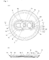
- Fig. 1 shows a can lid according to a first embodiment of the present invention, wherein Fig. 1(A) is a plan view and Fig. 1(B) is a sectional view taken along the X1-X1 line of Fig. 1(A) , respectively.
- the illustrated can lid represents one intended to use in a can container for beverages by way of example. It is to be noted that although the thickness of each of components in Fig. 1(B) is expressed in an exaggerated form for convenience of description, the each component is actually made of thin plate of aluminum or steel and thus actually formed of the thin member.
- a can lid 1 As shown in Fig. 1 , a can lid 1 according to the illustrated embodiment has a circular can lid body 3 comprising an opening region 5 to be open to form a tap upon being opened and a tab 9 secured to the can lid body 3 with a rivet 7. A rear end of the tab (right end in Fig. 1(A) ) defines a pull-up section 9a on which a user's finger is hooked for pulling up.
- a properly designed guide section 10 is formed in the can lid body 3 at a location corresponding to the pull-up section 9a.
- the can lid body 3 has a circular configuration in plan view and adapted to seal an opening of a cylindrical can body having a bottom, though not shown.
- a turn-back section 3a is formed along a periphery of the can lid 1 for joining to the can body.
- a predetermined groove 3b is formed in an inner side with respect to the turn-back section 3a.
- the groove 3b is not essential but may be omitted.
- An area encircled by the groove provides a substantially flat plane and a central region of the can lid 3 disposed in an inner side relative to the flat plane is defined to be lower level than the flat plane via a stepped section 3d.
- the opening region 5 is formed in said central region of the can lid 3, which is to be open to form the tap upon being opened.
- the opening region 5 is configured to be cut out along a score 3c (imprint) assuming a partially elliptical contour extending from a tip end (left end in Fig. 1(A) ) toward the central region of the can lid 3.
- a score 3c imprint
- the opening region 5 would not be separated from the can lid body 3 even after the opening operation.
- the tab 9 fixed to the can lid body 3 will now be described.
- the tab 9' is substantially semi-circular in its front end (left end in Fig. 1(A) ) and substantially rectangular in its rear end (right end in Fig. 1(A) ).
- the front end of the tab is disposed at a location abutting to the opening region, so that a pulling-up action of the tab can press the opening region downward.
- the rear end of the tab 9 forms a pull-up section 9a, defining a section allowing for a user's finger to be hooked for pulling up.
- the tab 9 is fixed to the can lid body 3 via a fastening area 9b with use of the rivet 7, which will be described later.
- a semi-circular slit 9c having a predetermined width is formed in the pull-up section 9a of the tab 9 around the rivet 7.
- a finger hooking slot 9d is formed in the tab 9 at a location adjacent to the pull-up section 9a.
- the guide section 10 is formed in a finger inserting recess 8 of the can lid body 3 at an area adjacent to the pull-up section 9a.
- the finger inserting recess 8 defines a more concavely recessed portion than the surrounding area.
- This finger inserting recess 8 is the area in which a guide section 10 is additionally formed.
- the guide section 10 according to the illustrated embodiment is formed with a sloped guide plane 10b of a triangular shape with an apex 10a located proximal to the center of the pull-up section 9a and a guide wall 10d connecting to each oblique line 10c of the guide plane.
- a rear end of the finger inserting recess 8 (right end in Fig.
- respective guide walls 10d connecting to respective oblique lines 10c are configured such that a distance between the guide walls 10d is gradually narrowing toward the apex 10a so as to guide the user's finger in the opening action into the center of the pull-up section 9a.
- the guide section 10 may be formed with a sloped guide plane having its concavity getting deeper toward the apex and a guide wall connecting to the guide plane. It is to be noted that the guide section 10 may be formed by the press work using a die or the like simultaneously with the formation of the can lid body 3 or may be formed in a separate process after the formation of the can lid body 3.
- the rivet 7 serves to fasten the tab 9 to the can lid body 3.
- the rivet 7 in the illustrated embodiment is formed integrally with the can lid body 3. Specifically, the rivet 7 as before fastening the tab 9 exhibits a circular column configuration protruding upward from the central region of the can lid body 3. Then, the tab is inserted over the circular column-like rivet and the rivet is pressed and collapsed to define the configuration of the rivet 7 as shown in Fig. 1 . It is to be noted that since the rivet 7 of the illustrated embodiment is circular configuration, and if the tab turning had arisen in the manufacturing process, the user to open the can lid could correct the tab turning by himself/herself. This is an aspect of great difference from the prior art that has taught the rivet having an elliptical shape in cross section.
- the can lid 1 is essentially contemplated to be joined with a can body (not shown) and used in the form of a can container, and the description is herein given on the premise of the can lid having been already joined with the can body.
- a user holds the can body to stable the can container.
- he/she tries to hook a finger on the pull-up section 9a of the tab 9.
- the user's finger is guided to the site near the pull-up section 9a.
- the guide section 10 is formed in the finger inserting recess 8.
- the finger is guided along the slope of the guide section 10 to near the guide section tip end 10a. Since the guide tip end 10a is positioned near the center of the pull-up section 9a, the user's finger in the opening action is accordingly led to near the center of the pull-up section 9a.
- the user can successfully hooked his/her finger on the pull-up section 9a to pull up the tab 9. Since the semi-circular slit 9c is formed in the tab 9 as described above, therefore in association with the pulling-up of the pull-up section 9a, the tab 9 is rotated around the vicinity of the rivet 7 and pulled up. As a result, the tip end of the tab 9 can press down the opening region 5. As the opening region 5 is pressed down, the opening region 5 tends to break along the score to form the tap.
- the guide section 10 comprises the sloped guide plane of the triangular shape having its apex located at a point proximal to the center of the pull-up section 9a of the tab 9 and at the same time the rear end of the pull-up section 9a is formed into a linear shape, therefore the physical relationship between the apex of the guide plane and the pull-up section can be easily recognized and any events of tab turning can be immediately made aware of.
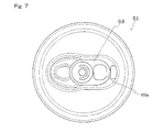
- This aspect is a significant difference from the can lid 61 having the circular pull-up section 69a of the tab 69 shown in Fig. 7 . Further, a type of imprint such as a groove may be disposed in the center of the pull-up section 9a of the tab 9. This provides more easy recognition of the physical relationship (tab turning) of the tab 9 relative to the can lid body.
- a can lid 11 according to a second embodiment of the present invention will now be described with reference to Fig. 2 .
- the can lid 11 according to the illustrated embodiment is generally similar to the first embodiment except a guide section 20, and any duplicated descriptions may be herein omitted.
- a guide section 20 of the illustrated embodiment provides two stepped planes formed in a finger inserting recess 18 and configured such that the distance therebetween is gradually narrowing toward a center of a pull-up section 19a.
- the finger inserting recess 18 extends such that the two stepped planes extending from a rear end of the finger inserting recess 18 (right end in Fig. 2(B) ) toward an area adjacent to the pull-up section 19a defines a trapezoid.
- the depth of the concavity of the guide section 20 would not change as approaching to the area adjacent to the pull-up section 19a.
- the stepped plane for the purpose of the present invention is referred to the stepped plane comprising not only a vertical plane but also an oblique plane.
- the guide section 20 is constructed to from the two stepped planes defining a trapezoidal shape therebetween, therefore as a user places his/her finger into a finger inserting recess 18 and brings it close to the pull-up section 19a, the finger is guided along the stepped planes so that the finger can be hooked in the center of the pull-up section 19a. If the pull-up section 19a is pulled up in the above condition, the tab turning can be successfully avoided.
- the guide section geometry is not limited to the trapezoidal shape but may be formed in a triangular shape. In other words, any geometry that can guide the user's finger into the center of the pull-up section 19a of the tab 19 may be employed.
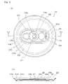
- a can lid 21 according to respective examples of a third embodiment will now be described with reference to Figs. 3 and 4 . Since main components of the can lid 21 of the illustrated embodiment are similar to those in the first embodiment, any duplicated descriptions on the common parts may be herein omitted.
- a positioning section 30 is formed in place of the guide section 10 in the first embodiment.
- the positioning section 30 is an additional recessed section defined in a finger inserting recess 28 and disposed in an area adjacent to a center of a pull-up section 29a.
- the positioning section 30 defines an elliptical recessed section, the geometry thereof is not particularly limited. In other words, it should be only a little more recessed than the finger inserting recess 28.
- the positioning section 30 is defined by the recessed portion, when a user inserts his/her finger in the finger inserting recess 28 and brings it close to the pull-up section 29a, he/she may recognize the positioning section 30, which facilitates his/her hooking action of the finger in the center of the pull-up section 29a. If the pull-up section 29a is pulled up in this condition, the tab turning can be successfully avoided.
- a positioning section 30a provides two stepped planes exclusively defined in an area adjacent to the center of the pull-up section of the tab 29.
- the stepped planes are configured such that a distance therebetween is gradually narrowing toward the area adjacent to the pull-up section and the two planes intersect with each other in a point adjacent to the pull-up section to thereby form such as an apex of a triangle. This allows for the user's finger to be successfully positioned in the center of the pull-up section with the aid of respective stepped planes.
- a positioning section 30b according to the third example also provides two stepped planes exclusively defined in an area adjacent to the center of the pull-up section of the tab 29. Those stepped planes are configured such that a distance therebetween is gradually narrowing toward the area adjacent to the pull-up section but spaced apart from each other by a predetermined distance in the area adjacent to the pull-up section to thereby define a geometry like a trapezoid. This feature can also facilitate the hooking action by the user in hooking the finger in the center of the pull-up section with the aid of respective stepped planes.
- a positioning section 30c according to the fourth example is configured as a part of the finger inserting recess. Specifically, the finger inserting recess in an area adjacent to the center of the pull-up section of the tab 29 has a smaller width, so that a finger tip of the user can be positioned in this narrow positioning section.
- the positioning section 30 is formed in place of the guide section 10 employed in the first embodiment, the present invention is not limited to this. Specifically, the positioning section 30 may be additionally provided in combination with the guide section 10 according to the first embodiment.
- the tab turning can be more effectively prevented by constructing the can lid by using such a combination of the guide section 10 with the positioning section 30.
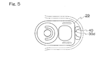
- a similar effect can be also obtained by constructing the can lid by using the combination of the stepped plane defining the guide section 40 with the stepped plane defining the positioning section 30d, as shown in Fig. 5 .
- a fourth embodiment of the present invention is a can container using the can lid 1, 11 or 21 as discussed above.
- the can lid is joined to a cylindrical can body having a bottom to form a can container.
- the can lid is placed in an open end of the can body and a periphery of the can lid is turned back together with an open end portion of the can body.
- the present invention has been described and illustrated primarily with respect to the can container for beverages, the present invention is not limited to this. Specifically, the present invention may be applied to a can container of a type that can be used for foods and seasonings.
- the can container for foods may be structured such that the can lid in its entire area can be separated from the can container. Nevertheless, since the tab can be pulled up to open the can lid in a similar manner to that in the can container for beverages, therefore the similar effect can be obtained by forming the guide section and/or the positioning section in an area adjacent to the center of the pull-up section.
- the present invention is applicable to a can container for containing beverages and foods and the like.
Landscapes
- Engineering & Computer Science (AREA)
- Mechanical Engineering (AREA)
- Containers Opened By Tearing Frangible Portions (AREA)
- Table Devices Or Equipment (AREA)
- Closures For Containers (AREA)
Abstract
Description
- The present invention relates to a can lid and a can container equipped with the same according to the preamble of
claim 1, and particularly to a can lid made in such a type that an opening region of the can lid can be opened by pulling up what is called a tab and also to a can container equipped with the same can lid. - Conventionally, a can container commonly used for containing soft drink, alcoholic beverages and even foods and the like comprises a cylindrical can body having a bottom and a disk-like can lid for closing an open end of the can body. Recently, the can lids used in the above type of can container have mostly employed a certain type of tab, or what is called a stay-on tab, in which the tab is placed in a partially coupled state with the can body even after opening of the can lid. This stay-on type tab is attached to the can lid via a rivet arranged integrally in a substantially central region of a can lid body. A conventional can container according to the preamble of
claim 1 is disclosed inUS 5038956 comprising an opener having a handle end and a finger indentation for improving access beneath the handle end. - In such fastening of the tab with use of the rivet, if the used rivet has a poor fastening force, the tab could be easily turned around the rivet in parallel with the can lid body, or substantially along the horizontal plane. This is a phenomenon referred to as "tab turning". The tab turning may occur in a manufacturing process and/or a packaging process and may also possibly occur when a user pulls up the tab at a location offset from a central region of a lift-up section of the tab.
- The event of the tab turning can alter the physical relationship between an opening region (tear-strip) and a tab tip end (tab nose). Since the tab nose defines a section serving to apply a force to the opening region during the opening process, any change in the above physical relationship could prohibit a predetermined pressing force from being obtained. In addition, if there is occurrence of severe tab turning, the tab nose may be shifted away from the opening region, bringing about obstacles in opening and ending up with a problem of the opening ability.
- In order to avoid such problems, many different means have been used to prevent the tab turning. There is one such related art technique by way of example that has employed a non-circular rivet so as to prevent the tab turning. In the related art technique, the rivet is configured to have an elliptical shape in cross section, so that the tab would not turn even if such a great force that could turn the tab were applied to the tab. In this technique, the conventional design can be still employed for other aspects than the rivet geometry (see following related art 1). There are other related art techniques as disclosed, including one type of can lid that includes a protrusion referred to as a tab dimple disposed in the can lid and another type of can lid that is manufactured by using a favorably modified pressing degree of a rivet (see following related art 2).
-
Fig. 6 shows a related art technique, in which afinger inserting recess 58 is formed in an area of the can lid body adjacent to a pull-upsection 59a of atab 59. Thefinger inserting recess 58 defines a recess to facilitate hooking action by a user in hooking his/her finger on the pull-upsection 59a of thetab 59. - [Related Art 1]
- Japanese Patent Public Disclosure No.
2002-179062
- Japanese Patent Public Disclosure No.
- [Related Art 2]
- Japanese Patent Public Disclosure No.
2004-196349
- Japanese Patent Public Disclosure No.
- However, there are some drawbacks in association with the above-described related art techniques, as will be described below. Specifically, forming the non-circular cross-section geometry of the rivet requires that a press die should be modified to have a particular configuration for forming the above rivet. In addition, in case of the tab that is fixed in a position rotationally offset from a designed location, even if the user may notice the actual tab turning, it would be impossible to correct the tab turning anymore.
- Moreover, in the technique that teaches the protrusion referred to as the tab dimple formed in the can lid body, the tab, if pulled up only by a small distance, could depart from the protrusion, and consequently, any rotational force applied to the tab in the above condition may cause the tab turning. Further, even if the pressing degree of the rivet were favorably modified, the tab turning would not be fully eliminated so far as the cross sectional geometry of the rivet is circular.
- Further in the technique employing the finger inserting recess, the finger inserting recess has a predetermined width but it is not serving to allow a user's finger to be guided to the center of the pull-up section of the tab, again failing to prevent the tab turning completely.
- The present invention has been made based on a finding that the problem of the tab turning could not arise, if the tab is pulled up in its proper region, without any inventive modification to be applied, such as the rivet cross sectional geometry and the like as disclosed in the related art techniques.
- Specifically, the present invention provides a can lid according to
claim 1 comprising a can lid body having an opening region to be open upon being opened and a tab fixed to the can lid body, the tab comprising a pull-up section on which a user's finger is hooked in his/her opening action, said can lid characterized in that the can lid body comprises a guide section for guiding the user's finger to a center of the pull-up section wherein a positioning section is formed in the can lid body for positioning the user's finger in the center of the pull-up section. The present invention further provides a can container comprising the can lid as defined above. - According to the present invention, since the user's finger is guided to the center of the pull-up section of the tab in an appropriate manner, therefore the tab turning can be effectively prevented. More advantageously, for a person having a weak eyesight in handling the can lid, his/her finger is guided in an appropriate manner, so that he/she can pull-up the tab appropriately.
- Further, even if the tab is fixed as in the condition where the tab turning has arisen during the manufacturing process, a cross sectional geometry of a rivet that is circular still allows the user to correct the tab turning by himself/herself (the correction is not possible with the non-circular cross sectional geometry of the rivet).
-
-
Fig. 1 shows a can lid according to a first embodiment of the present invention, whereinFig. 1(A) is a plan view andFig. 1(B) is a sectional view taken along X1-X1 line ofFig. 1(A) ; -
Fig. 2 shows a can lid according to a second embodiment of the present invention, whereinFig. 2(A) is a plan view andFig. 2(B) is a sectional view taken along X2-X2 line ofFig. 2(A) ; -
Fig. 3 shows a can lid according to a first example of a third embodiment, whereinFig. 3(A) is a plan view andFig. 3(B) is a sectional view taken along X3-X3 line ofFig. 3(A) ; -
Fig. 4 is a partial plan view of a can lid according to the third embodiment of the present invention, whereinFig. 4(A) is a second example,Fig. 4(B) is a third example, andFig. 4(C) is a fourth example, respectively, of the third embodiment; -
Fig. 5 is a partial plan view of a can lid according to yet another example of the present invention; -
Fig. 6 shows a can lid according to the prior art, whereinFig. 6(A) is a plan view andFig. 6(B) is a sectional view taken along the X4-X4 line ofFig. 6(A) ; and -
Fig. 7 is a plan view showing another example of a can lid according the prior art. -
- 1, 11, 21
- Can lid
- 3, 13, 23
- Can lid body
- 5, 15, 25
- Opening region
- 7, 17, 27
- Rivet
- 9, 19, 29
- Tab
- 9a, 19a, 29a
- Pull-up section
- 10, 20
- Guide section
- 10b
- Guide plane
- 10c
- Oblique line
- 10d
- Guide wall
- 30
- Positioning section
- An embodiment of the present invention will now be described with reference to the attached drawings.
Fig. 1 shows a can lid according to a first embodiment of the present invention, whereinFig. 1(A) is a plan view andFig. 1(B) is a sectional view taken along the X1-X1 line ofFig. 1(A) , respectively. The illustrated can lid represents one intended to use in a can container for beverages by way of example. It is to be noted that although the thickness of each of components inFig. 1(B) is expressed in an exaggerated form for convenience of description, the each component is actually made of thin plate of aluminum or steel and thus actually formed of the thin member. - As shown in
Fig. 1 , acan lid 1 according to the illustrated embodiment has a circularcan lid body 3 comprising anopening region 5 to be open to form a tap upon being opened and atab 9 secured to thecan lid body 3 with arivet 7. A rear end of the tab (right end inFig. 1(A) ) defines a pull-upsection 9a on which a user's finger is hooked for pulling up. In addition, a properly designedguide section 10 is formed in thecan lid body 3 at a location corresponding to the pull-upsection 9a. Each of the components will now be described in detail. - As previously mentioned, the
can lid body 3 has a circular configuration in plan view and adapted to seal an opening of a cylindrical can body having a bottom, though not shown. A turn-back section 3a is formed along a periphery of thecan lid 1 for joining to the can body. In addition, apredetermined groove 3b is formed in an inner side with respect to the turn-back section 3a. However, it is to be appreciated that thegroove 3b is not essential but may be omitted. An area encircled by the groove provides a substantially flat plane and a central region of thecan lid 3 disposed in an inner side relative to the flat plane is defined to be lower level than the flat plane via a steppedsection 3d. Further, theopening region 5 is formed in said central region of thecan lid 3, which is to be open to form the tap upon being opened. Theopening region 5 is configured to be cut out along ascore 3c (imprint) assuming a partially elliptical contour extending from a tip end (left end inFig. 1(A) ) toward the central region of thecan lid 3. However, it is to be noted that since thescore 3c is not formed to extend entirely along a periphery of theopening region 5, theopening region 5 would not be separated from thecan lid body 3 even after the opening operation. - The
tab 9 fixed to thecan lid body 3 will now be described. The tab 9' is substantially semi-circular in its front end (left end inFig. 1(A) ) and substantially rectangular in its rear end (right end inFig. 1(A) ). The front end of the tab is disposed at a location abutting to the opening region, so that a pulling-up action of the tab can press the opening region downward. On the other hand, the rear end of thetab 9 forms a pull-upsection 9a, defining a section allowing for a user's finger to be hooked for pulling up. Thetab 9 is fixed to thecan lid body 3 via afastening area 9b with use of therivet 7, which will be described later. Asemi-circular slit 9c having a predetermined width is formed in the pull-upsection 9a of thetab 9 around therivet 7. Afinger hooking slot 9d is formed in thetab 9 at a location adjacent to the pull-upsection 9a. - A
guide section 10 will now be described. Theguide section 10 is formed in afinger inserting recess 8 of thecan lid body 3 at an area adjacent to the pull-upsection 9a. Thefinger inserting recess 8 defines a more concavely recessed portion than the surrounding area. Thisfinger inserting recess 8 is the area in which aguide section 10 is additionally formed. Theguide section 10 according to the illustrated embodiment is formed with a slopedguide plane 10b of a triangular shape with an apex 10a located proximal to the center of the pull-upsection 9a and aguide wall 10d connecting to eachoblique line 10c of the guide plane. To explain specifically, a rear end of the finger inserting recess 8 (right end inFig. 1(A) ) defines a most concavely recessed portion and the concavity is getting shallower gradually from the rear end of thefinger inserting recess 8 toward the center of the pull-upsection 9a. The concavity is shallowest in the vicinity of the pull-upsection 9a (seeFig. 1(B) ). In association with this configuration,respective guide walls 10d connecting torespective oblique lines 10c are configured such that a distance between theguide walls 10d is gradually narrowing toward the apex 10a so as to guide the user's finger in the opening action into the center of the pull-upsection 9a. It is to be appreciated in this connection that although theguide plane 10b is tilted with respect to a horizontal plane such that the concavity is getting shallower toward the apex 10a in the embodiment as shown inFig. 1 , the present invention is not limited to this. Specifically, theguide section 10 may be formed with a sloped guide plane having its concavity getting deeper toward the apex and a guide wall connecting to the guide plane. It is to be noted that theguide section 10 may be formed by the press work using a die or the like simultaneously with the formation of thecan lid body 3 or may be formed in a separate process after the formation of thecan lid body 3. - The
rivet 7 will now be described. Therivet 7 serves to fasten thetab 9 to thecan lid body 3. Therivet 7 in the illustrated embodiment is formed integrally with thecan lid body 3. Specifically, therivet 7 as before fastening thetab 9 exhibits a circular column configuration protruding upward from the central region of thecan lid body 3. Then, the tab is inserted over the circular column-like rivet and the rivet is pressed and collapsed to define the configuration of therivet 7 as shown inFig. 1 . It is to be noted that since therivet 7 of the illustrated embodiment is circular configuration, and if the tab turning had arisen in the manufacturing process, the user to open the can lid could correct the tab turning by himself/herself. This is an aspect of great difference from the prior art that has taught the rivet having an elliptical shape in cross section. - An operation of the
can lid 1 according to the illustrated embodiment will now be described. It is to be noted that although only thecan lid 1 is shown inFig. 1 , the can lid of the present invention is essentially contemplated to be joined with a can body (not shown) and used in the form of a can container, and the description is herein given on the premise of the can lid having been already joined with the can body. - Firstly, a user holds the can body to stable the can container. Secondly, he/she tries to hook a finger on the pull-up
section 9a of thetab 9. In this step, owing to thefinger inserting recess 8 formed in the vicinity of the pull-upsection 9a, the user's finger is guided to the site near the pull-upsection 9a. Additionally, theguide section 10 is formed in thefinger inserting recess 8. With the aid of this, as the user in the opening action tries to place his/her finger close to the pull-upsection 9a, the finger is guided along the slope of theguide section 10 to near the guide section tip end 10a. Since the guide tip end 10a is positioned near the center of the pull-upsection 9a, the user's finger in the opening action is accordingly led to near the center of the pull-upsection 9a. - In this condition, the user can successfully hooked his/her finger on the pull-up
section 9a to pull up thetab 9. Since thesemi-circular slit 9c is formed in thetab 9 as described above, therefore in association with the pulling-up of the pull-upsection 9a, thetab 9 is rotated around the vicinity of therivet 7 and pulled up. As a result, the tip end of thetab 9 can press down theopening region 5. As theopening region 5 is pressed down, theopening region 5 tends to break along the score to form the tap. - As described above, in the
can lid 1 of the illustrated embodiment, since the user's finger is guided to the center of the pull-upsection 9a by theguide section 10, therefore it becomes possible to pull up thetab 9 appropriately and thus to prevent the tab turning reliably. Further advantageously, in the illustrated embodiment, since theguide section 10 comprises the sloped guide plane of the triangular shape having its apex located at a point proximal to the center of the pull-upsection 9a of thetab 9 and at the same time the rear end of the pull-upsection 9a is formed into a linear shape, therefore the physical relationship between the apex of the guide plane and the pull-up section can be easily recognized and any events of tab turning can be immediately made aware of. This aspect is a significant difference from thecan lid 61 having the circular pull-upsection 69a of thetab 69 shown inFig. 7 . Further, a type of imprint such as a groove may be disposed in the center of the pull-upsection 9a of thetab 9. This provides more easy recognition of the physical relationship (tab turning) of thetab 9 relative to the can lid body. - A
can lid 11 according to a second embodiment of the present invention will now be described with reference toFig. 2 . Thecan lid 11 according to the illustrated embodiment is generally similar to the first embodiment except aguide section 20, and any duplicated descriptions may be herein omitted. - A
guide section 20 of the illustrated embodiment provides two stepped planes formed in afinger inserting recess 18 and configured such that the distance therebetween is gradually narrowing toward a center of a pull-upsection 19a. Specifically in the illustrated embodiment, thefinger inserting recess 18 extends such that the two stepped planes extending from a rear end of the finger inserting recess 18 (right end inFig. 2(B) ) toward an area adjacent to the pull-upsection 19a defines a trapezoid. It is to be noted that differently from the first embodiment, the depth of the concavity of theguide section 20 would not change as approaching to the area adjacent to the pull-upsection 19a. It is needless to say that the stepped plane for the purpose of the present invention is referred to the stepped plane comprising not only a vertical plane but also an oblique plane. - As described herein, since the
guide section 20 is constructed to from the two stepped planes defining a trapezoidal shape therebetween, therefore as a user places his/her finger into afinger inserting recess 18 and brings it close to the pull-upsection 19a, the finger is guided along the stepped planes so that the finger can be hooked in the center of the pull-upsection 19a. If the pull-upsection 19a is pulled up in the above condition, the tab turning can be successfully avoided. It is to be noted that the guide section geometry is not limited to the trapezoidal shape but may be formed in a triangular shape. In other words, any geometry that can guide the user's finger into the center of the pull-upsection 19a of thetab 19 may be employed. - A
can lid 21 according to respective examples of a third embodiment will now be described with reference toFigs. 3 and4 . Since main components of thecan lid 21 of the illustrated embodiment are similar to those in the first embodiment, any duplicated descriptions on the common parts may be herein omitted. - In a first example of the illustrated embodiment of
Fig. 3 , apositioning section 30 is formed in place of theguide section 10 in the first embodiment. Thepositioning section 30 is an additional recessed section defined in afinger inserting recess 28 and disposed in an area adjacent to a center of a pull-upsection 29a. Although thepositioning section 30 defines an elliptical recessed section, the geometry thereof is not particularly limited. In other words, it should be only a little more recessed than thefinger inserting recess 28. - As described herein, since the
positioning section 30 is defined by the recessed portion, when a user inserts his/her finger in thefinger inserting recess 28 and brings it close to the pull-upsection 29a, he/she may recognize thepositioning section 30, which facilitates his/her hooking action of the finger in the center of the pull-upsection 29a. If the pull-upsection 29a is pulled up in this condition, the tab turning can be successfully avoided. - A second example of the illustrated embodiment will now be described with reference to
Fig. 4(A) . Apositioning section 30a according to the second example provides two stepped planes exclusively defined in an area adjacent to the center of the pull-up section of thetab 29. The stepped planes are configured such that a distance therebetween is gradually narrowing toward the area adjacent to the pull-up section and the two planes intersect with each other in a point adjacent to the pull-up section to thereby form such as an apex of a triangle. This allows for the user's finger to be successfully positioned in the center of the pull-up section with the aid of respective stepped planes. - A third example of the illustrated embodiment will now be described with reference to
Fig. 4(B) . Apositioning section 30b according to the third example also provides two stepped planes exclusively defined in an area adjacent to the center of the pull-up section of thetab 29. Those stepped planes are configured such that a distance therebetween is gradually narrowing toward the area adjacent to the pull-up section but spaced apart from each other by a predetermined distance in the area adjacent to the pull-up section to thereby define a geometry like a trapezoid. This feature can also facilitate the hooking action by the user in hooking the finger in the center of the pull-up section with the aid of respective stepped planes. - Further, a fourth example of the illustrated embodiment will now be described with reference to
Fig. 4(C) . Apositioning section 30c according to the fourth example is configured as a part of the finger inserting recess. Specifically, the finger inserting recess in an area adjacent to the center of the pull-up section of thetab 29 has a smaller width, so that a finger tip of the user can be positioned in this narrow positioning section. - It is to be noted that although in the above first example, the
positioning section 30 is formed in place of theguide section 10 employed in the first embodiment, the present invention is not limited to this. Specifically, thepositioning section 30 may be additionally provided in combination with theguide section 10 according to the first embodiment. The tab turning can be more effectively prevented by constructing the can lid by using such a combination of theguide section 10 with thepositioning section 30. A similar effect can be also obtained by constructing the can lid by using the combination of the stepped plane defining theguide section 40 with the stepped plane defining the positioning section 30d, as shown inFig. 5 . - A fourth embodiment of the present invention is a can container using the
can lid - It is to be noted that although the present invention has been described and illustrated primarily with respect to the can container for beverages, the present invention is not limited to this. Specifically, the present invention may be applied to a can container of a type that can be used for foods and seasonings. Generally, the can container for foods may be structured such that the can lid in its entire area can be separated from the can container. Nevertheless, since the tab can be pulled up to open the can lid in a similar manner to that in the can container for beverages, therefore the similar effect can be obtained by forming the guide section and/or the positioning section in an area adjacent to the center of the pull-up section.
- The present invention is applicable to a can container for containing beverages and foods and the like.
Claims (5)
- A can lid (1) comprising a can lid body (3) having an opening region (5) to be open upon being opened and a tab (9) fixed to said can lid body (3),
said tab (9) comprising a pull-up section (9a) on which a user's finger is hooked in his/her opening action; said can lid (1) characterized in that:said can lid body (3) comprises a guide section (10) for guiding said user's finger to a center of said pull-up section (9a),wherein said guide section (10) comprises a guide plane (10b) having a width gradually narrowing toward said center of said pull-up section (9a) and a guide wall (10d) connected to each oblique line (10c) of said guide plane (10b). - A can lid claimed in claim 1, characterized in that said guide plane (10b) is a sloped plane defining a triangular shape.
- A can lid claimed in claim 1, characterized in that said guide plane (10b) is tilted such that a depth is getting shallower toward said pull-up section (9a).
- A can lid claimed in any one of claims 1 to 7, characterized in that said pull-up section (9a) is formed into a linear shape.
- A can container characterized in that said can container comprises a can lid (1) claimed in any one of claims 1 to 4.
Priority Applications (1)
| Application Number | Priority Date | Filing Date | Title |
|---|---|---|---|
| EP10155030.9A EP2186739B1 (en) | 2005-02-23 | 2005-12-21 | Can lid and can container equipped with the same |
Applications Claiming Priority (2)
| Application Number | Priority Date | Filing Date | Title |
|---|---|---|---|
| JP2005047305A JP4490847B2 (en) | 2005-02-23 | 2005-02-23 | Can lid and can container equipped with the same |
| PCT/JP2005/023506 WO2006090525A1 (en) | 2005-02-23 | 2005-12-21 | Can lid and can container with the same |
Related Child Applications (1)
| Application Number | Title | Priority Date | Filing Date |
|---|---|---|---|
| EP10155030.9 Division-Into | 2010-03-01 |
Publications (3)
| Publication Number | Publication Date |
|---|---|
| EP1854729A1 EP1854729A1 (en) | 2007-11-14 |
| EP1854729A4 EP1854729A4 (en) | 2009-05-13 |
| EP1854729B1 true EP1854729B1 (en) | 2011-08-24 |
Family
ID=36927173
Family Applications (2)
| Application Number | Title | Priority Date | Filing Date |
|---|---|---|---|
| EP05820350A Not-in-force EP1854729B1 (en) | 2005-02-23 | 2005-12-21 | Can lid and can container with the same |
| EP10155030.9A Not-in-force EP2186739B1 (en) | 2005-02-23 | 2005-12-21 | Can lid and can container equipped with the same |
Family Applications After (1)
| Application Number | Title | Priority Date | Filing Date |
|---|---|---|---|
| EP10155030.9A Not-in-force EP2186739B1 (en) | 2005-02-23 | 2005-12-21 | Can lid and can container equipped with the same |
Country Status (11)
| Country | Link |
|---|---|
| US (1) | US9010561B2 (en) |
| EP (2) | EP1854729B1 (en) |
| JP (1) | JP4490847B2 (en) |
| KR (1) | KR101172337B1 (en) |
| CN (1) | CN101128361B (en) |
| AT (1) | ATE521543T1 (en) |
| AU (1) | AU2005328082B2 (en) |
| ES (2) | ES2367579T3 (en) |
| HK (1) | HK1111966A1 (en) |
| TW (1) | TW200630274A (en) |
| WO (1) | WO2006090525A1 (en) |
Families Citing this family (12)
| Publication number | Priority date | Publication date | Assignee | Title |
|---|---|---|---|---|
| JP4879802B2 (en) * | 2007-03-30 | 2012-02-22 | ユニバーサル製缶株式会社 | Can lid and can lid manufacturing method |
| JP4979128B2 (en) * | 2007-09-11 | 2012-07-18 | 大和製罐株式会社 | Easy-to-open can lid |
| USD638704S1 (en) | 2010-12-10 | 2011-05-31 | Pactiv Corporation | Container lid |
| USD637489S1 (en) | 2010-12-10 | 2011-05-10 | Pactiv Corporation | Pull grip feature of a container lid |
| JP6009910B2 (en) * | 2012-11-07 | 2016-10-19 | 昭和アルミニウム缶株式会社 | Can lid and beverage can |
| WO2014150180A1 (en) * | 2013-03-14 | 2014-09-25 | Crown Packaging Technology, Inc. | Vented beverage can end having an anti-tension score |
| HUE050822T2 (en) * | 2017-04-05 | 2021-01-28 | Gregor Anton Piech | Metallic can lid |
| US10894630B2 (en) * | 2017-08-30 | 2021-01-19 | Stolle Machinery Company, Llc | Pressure can end compatible with standard can seamer |
| WO2019194237A1 (en) * | 2018-04-03 | 2019-10-10 | 東洋製罐株式会社 | Can lid |
| JP7242193B2 (en) * | 2018-04-27 | 2023-03-20 | 大和製罐株式会社 | Tubs, can lids and methods of manufacturing can lids |
| CN108995949B (en) * | 2018-07-05 | 2023-11-10 | 厦门保沣集团有限公司 | Pop-top can cover and processing method of pull ring of pop-top can cover |
| US20230130506A1 (en) * | 2021-10-26 | 2023-04-27 | HEX20, Inc. | Beverage container |
Family Cites Families (43)
| Publication number | Priority date | Publication date | Assignee | Title |
|---|---|---|---|---|
| US3437227A (en) * | 1968-02-21 | 1969-04-08 | Continental Can Co | Easy opening container |
| US3744666A (en) * | 1971-12-27 | 1973-07-10 | Aluminum Co Of America | Easy opening device in a container wall |
| US3900128A (en) * | 1973-03-30 | 1975-08-19 | Fraze Ermal C | Easy open can end resistant to pressure |
| CA1034520A (en) * | 1974-12-04 | 1978-07-11 | Reynolds Metals Company | Easy-open wall |
| AU1467476A (en) * | 1975-07-16 | 1977-12-15 | Crown Cork & Seal Co | Easy-opening can end |
| US3989161A (en) * | 1976-03-03 | 1976-11-02 | American Can Company | Container end closure |
| JPS5652978A (en) | 1979-10-08 | 1981-05-12 | Hitachi Ltd | Skew generating position detection circuit |
| JPS56104763A (en) | 1980-01-21 | 1981-08-20 | Matsushita Electric Works Ltd | Manufacture of inorganic hardened body |
| US4367996A (en) * | 1981-02-11 | 1983-01-11 | National Steel Corporation | Tab opener end closure assembly method |
| JPS5812144U (en) * | 1981-07-16 | 1983-01-26 | 東洋製罐株式会社 | Easy-to-open can lid |
| US4417668A (en) * | 1981-09-03 | 1983-11-29 | Stolle Research And Development Corporation | Easy open can end with pull tab having retained tear strip with stress relief means |
| US4397403A (en) * | 1981-09-18 | 1983-08-09 | Guimarin Container Co., Incorporated | Container opening apparatus with captured tab |
| US4524879A (en) * | 1984-06-18 | 1985-06-25 | Van Dorn Company | Can end pour spout and pull tab construction |
| MX173559B (en) * | 1987-01-23 | 1994-03-16 | Weirton Steel Corp | END COVERS WITH CONTROLLED OPENING COMFORT FEATURE, WITH ABUSE-RESISTANT SAFETY EDGE |
| US5038956A (en) * | 1988-01-22 | 1991-08-13 | Weirton Steel Corporation | Abuse resistant, safety-edge, controlled-opening convenience-feature end closures |
| JPH0754623Y2 (en) * | 1989-06-02 | 1995-12-18 | 株式会社ユニシアジェックス | Plunger pump |
| JPH035982A (en) | 1989-06-02 | 1991-01-11 | Nec Corp | Magnetic head protector |
| JPH0314455A (en) * | 1989-06-06 | 1991-01-23 | Kazuo Ariyoshi | Recess for use in unstoppering beverage can |
| JPH0352786A (en) | 1989-07-18 | 1991-03-06 | Sumitomo Metal Ind Ltd | Liner welding method for tube inside surface |
| JPH0352786U (en) * | 1989-09-29 | 1991-05-22 | ||
| JPH0380678U (en) * | 1989-11-30 | 1991-08-19 | ||
| US5062542A (en) * | 1989-12-13 | 1991-11-05 | City Of Hope | Easy-open and reclosable container |
| JPH0829781B2 (en) * | 1990-11-28 | 1996-03-27 | 東洋製罐株式会社 | Impact-resistant easy-opening can lid and its manufacturing method |
| US5129541A (en) * | 1991-06-04 | 1992-07-14 | Buhrke Industries, Inc. | Easy open ecology end for cans |
| JPH0589231A (en) | 1991-09-30 | 1993-04-09 | Toshiba Corp | Image reader |
| JPH0589231U (en) * | 1992-05-19 | 1993-12-07 | 北海製罐株式会社 | Easy open can lid |
| US5224618A (en) * | 1992-06-22 | 1993-07-06 | Garbiso Michael J | Easy opening tab for container |
| JPH0829781A (en) | 1994-07-15 | 1996-02-02 | Toshiba Corp | Liquid crystal display device |
| JPH08169445A (en) * | 1994-12-19 | 1996-07-02 | Hirofumi Tsumeta | Pull-tab can |
| JPH0986538A (en) * | 1995-09-21 | 1997-03-31 | Satoru Yamaguchi | Easy open type can top |
| US6050440A (en) * | 1996-01-05 | 2000-04-18 | Aluminum Company Of America | Easy open container end, method of manufacture, and tooling |
| JPH11105870A (en) * | 1997-10-02 | 1999-04-20 | Akira Ishida | Drink can opening equipment |
| JPH11321862A (en) * | 1998-05-18 | 1999-11-24 | Kyo Meifu | Stay-on-tab easy lid opening structure |
| JP2000043864A (en) * | 1998-07-30 | 2000-02-15 | Kenji Yanagimachi | Can with vicinity of tab on upper face dented deep |
| US6202881B1 (en) * | 1998-10-22 | 2001-03-20 | Charles N. Chiang | Beverage container with easy cleaning upper panel |
| US6138856A (en) * | 1999-04-29 | 2000-10-31 | Ghim; Yongjae | Container end closure |
| JP2001130560A (en) * | 1999-11-10 | 2001-05-15 | Masahito Kitami | Can having pull-top |
| JP2002059928A (en) * | 2000-08-16 | 2002-02-26 | Mitsubishi Materials Corp | Can lid |
| JP2002179062A (en) | 2000-12-08 | 2002-06-26 | Asahi Beer Eng:Kk | Tab fitting method, and can lid using the method |
| JP4828693B2 (en) * | 2000-12-15 | 2011-11-30 | 俊介 細川 | Ultra-short pulse high voltage applied gas purification method |
| US6443323B1 (en) * | 2001-01-11 | 2002-09-03 | Mark V. Derose | Protective seal for cans |
| JP2004196349A (en) | 2002-12-18 | 2004-07-15 | Mitsubishi Materials Corp | Can lid |
| JP2004210318A (en) * | 2002-12-27 | 2004-07-29 | Jutaro Akita | Pull-top can |
-
2005
- 2005-02-23 JP JP2005047305A patent/JP4490847B2/en active Active
- 2005-12-21 CN CN2005800486076A patent/CN101128361B/en active Active
- 2005-12-21 ES ES05820350T patent/ES2367579T3/en active Active
- 2005-12-21 ES ES10155030T patent/ES2423293T3/en active Active
- 2005-12-21 WO PCT/JP2005/023506 patent/WO2006090525A1/en active Application Filing
- 2005-12-21 AT AT05820350T patent/ATE521543T1/en not_active IP Right Cessation
- 2005-12-21 US US11/884,671 patent/US9010561B2/en not_active Expired - Fee Related
- 2005-12-21 EP EP05820350A patent/EP1854729B1/en not_active Not-in-force
- 2005-12-21 EP EP10155030.9A patent/EP2186739B1/en not_active Not-in-force
- 2005-12-21 AU AU2005328082A patent/AU2005328082B2/en not_active Ceased
- 2005-12-21 KR KR1020077021680A patent/KR101172337B1/en active IP Right Grant
-
2006
- 2006-01-03 TW TW095100178A patent/TW200630274A/en unknown
-
2008
- 2008-06-24 HK HK08107007.8A patent/HK1111966A1/en unknown
Also Published As
| Publication number | Publication date |
|---|---|
| ATE521543T1 (en) | 2011-09-15 |
| KR20070104945A (en) | 2007-10-29 |
| EP1854729A1 (en) | 2007-11-14 |
| JP2006232306A (en) | 2006-09-07 |
| WO2006090525A1 (en) | 2006-08-31 |
| EP2186739B1 (en) | 2013-07-17 |
| ES2367579T3 (en) | 2011-11-04 |
| AU2005328082B2 (en) | 2012-07-05 |
| HK1111966A1 (en) | 2008-08-22 |
| EP2186739A1 (en) | 2010-05-19 |
| US9010561B2 (en) | 2015-04-21 |
| JP4490847B2 (en) | 2010-06-30 |
| TWI374838B (en) | 2012-10-21 |
| CN101128361A (en) | 2008-02-20 |
| KR101172337B1 (en) | 2012-08-14 |
| US20100032433A1 (en) | 2010-02-11 |
| EP1854729A4 (en) | 2009-05-13 |
| ES2423293T3 (en) | 2013-09-19 |
| TW200630274A (en) | 2006-09-01 |
| AU2005328082A1 (en) | 2006-08-31 |
| CN101128361B (en) | 2011-01-26 |
Similar Documents
| Publication | Publication Date | Title |
|---|---|---|
| EP1854729B1 (en) | Can lid and can container with the same | |
| US10053260B2 (en) | Full aperture beverage end | |
| US10556718B2 (en) | End closure with a ring pull actuated secondary vent | |
| EP3248897B1 (en) | Beverage can end with vent port | |
| US20130240526A1 (en) | Pt1-3 pull-tab | |
| KR100942867B1 (en) | Can covers and cans having the same | |
| ES2935495T3 (en) | Resealable Container Lid Arrangement | |
| JPH07132937A (en) | Easy-to-open lid | |
| JPH05178345A (en) | Easily openable can lid | |
| JPH09301364A (en) | Device for opening liquid containing can | |
| JP2002362553A (en) | Can lid having seesaw-type pull tab | |
| JP4975320B2 (en) | Can lid and can | |
| US3485411A (en) | Tab for easy-opening container | |
| KR101059533B1 (en) | Can lids and can containers with them | |
| JP2539915Y2 (en) | Can lid | |
| KR20080013643A (en) | Easy open beverage can | |
| JP2539913Y2 (en) | Can lid | |
| JPS6226352Y2 (en) | ||
| JP2539914Y2 (en) | Can lid | |
| KR20050006656A (en) | Beverage can lid having projection part |
Legal Events
| Date | Code | Title | Description |
|---|---|---|---|
| PUAI | Public reference made under article 153(3) epc to a published international application that has entered the european phase |
Free format text: ORIGINAL CODE: 0009012 |
|
| 17P | Request for examination filed |
Effective date: 20070919 |
|
| AK | Designated contracting states |
Kind code of ref document: A1 Designated state(s): AT BE BG CH CY CZ DE DK EE ES FI FR GB GR HU IE IS IT LI LT LU LV MC NL PL PT RO SE SI SK TR |
|
| DAX | Request for extension of the european patent (deleted) | ||
| A4 | Supplementary search report drawn up and despatched |
Effective date: 20090414 |
|
| RAP1 | Party data changed (applicant data changed or rights of an application transferred) |
Owner name: SUNTORY HOLDINGS LIMITED |
|
| 17Q | First examination report despatched |
Effective date: 20090722 |
|
| GRAP | Despatch of communication of intention to grant a patent |
Free format text: ORIGINAL CODE: EPIDOSNIGR1 |
|
| GRAS | Grant fee paid |
Free format text: ORIGINAL CODE: EPIDOSNIGR3 |
|
| GRAA | (expected) grant |
Free format text: ORIGINAL CODE: 0009210 |
|
| AK | Designated contracting states |
Kind code of ref document: B1 Designated state(s): AT BE BG CH CY CZ DE DK EE ES FI FR GB GR HU IE IS IT LI LT LU LV MC NL PL PT RO SE SI SK TR |
|
| REG | Reference to a national code |
Ref country code: GB Ref legal event code: FG4D |
|
| REG | Reference to a national code |
Ref country code: CH Ref legal event code: EP |
|
| REG | Reference to a national code |
Ref country code: IE Ref legal event code: FG4D |
|
| REG | Reference to a national code |
Ref country code: DE Ref legal event code: R096 Ref document number: 602005029806 Country of ref document: DE Effective date: 20111027 |
|
| REG | Reference to a national code |
Ref country code: ES Ref legal event code: FG2A Ref document number: 2367579 Country of ref document: ES Kind code of ref document: T3 Effective date: 20111104 |
|
| REG | Reference to a national code |
Ref country code: NL Ref legal event code: VDEP Effective date: 20110824 |
|
| LTIE | Lt: invalidation of european patent or patent extension |
Effective date: 20110824 |
|
| PG25 | Lapsed in a contracting state [announced via postgrant information from national office to epo] |
Ref country code: LT Free format text: LAPSE BECAUSE OF FAILURE TO SUBMIT A TRANSLATION OF THE DESCRIPTION OR TO PAY THE FEE WITHIN THE PRESCRIBED TIME-LIMIT Effective date: 20110824 Ref country code: SE Free format text: LAPSE BECAUSE OF FAILURE TO SUBMIT A TRANSLATION OF THE DESCRIPTION OR TO PAY THE FEE WITHIN THE PRESCRIBED TIME-LIMIT Effective date: 20110824 Ref country code: FI Free format text: LAPSE BECAUSE OF FAILURE TO SUBMIT A TRANSLATION OF THE DESCRIPTION OR TO PAY THE FEE WITHIN THE PRESCRIBED TIME-LIMIT Effective date: 20110824 Ref country code: NL Free format text: LAPSE BECAUSE OF FAILURE TO SUBMIT A TRANSLATION OF THE DESCRIPTION OR TO PAY THE FEE WITHIN THE PRESCRIBED TIME-LIMIT Effective date: 20110824 Ref country code: IS Free format text: LAPSE BECAUSE OF FAILURE TO SUBMIT A TRANSLATION OF THE DESCRIPTION OR TO PAY THE FEE WITHIN THE PRESCRIBED TIME-LIMIT Effective date: 20111224 Ref country code: PT Free format text: LAPSE BECAUSE OF FAILURE TO SUBMIT A TRANSLATION OF THE DESCRIPTION OR TO PAY THE FEE WITHIN THE PRESCRIBED TIME-LIMIT Effective date: 20111226 |
|
| REG | Reference to a national code |
Ref country code: AT Ref legal event code: MK05 Ref document number: 521543 Country of ref document: AT Kind code of ref document: T Effective date: 20110824 |
|
| PG25 | Lapsed in a contracting state [announced via postgrant information from national office to epo] |
Ref country code: LV Free format text: LAPSE BECAUSE OF FAILURE TO SUBMIT A TRANSLATION OF THE DESCRIPTION OR TO PAY THE FEE WITHIN THE PRESCRIBED TIME-LIMIT Effective date: 20110824 Ref country code: PL Free format text: LAPSE BECAUSE OF FAILURE TO SUBMIT A TRANSLATION OF THE DESCRIPTION OR TO PAY THE FEE WITHIN THE PRESCRIBED TIME-LIMIT Effective date: 20110824 Ref country code: GR Free format text: LAPSE BECAUSE OF FAILURE TO SUBMIT A TRANSLATION OF THE DESCRIPTION OR TO PAY THE FEE WITHIN THE PRESCRIBED TIME-LIMIT Effective date: 20111125 Ref country code: AT Free format text: LAPSE BECAUSE OF FAILURE TO SUBMIT A TRANSLATION OF THE DESCRIPTION OR TO PAY THE FEE WITHIN THE PRESCRIBED TIME-LIMIT Effective date: 20110824 Ref country code: SI Free format text: LAPSE BECAUSE OF FAILURE TO SUBMIT A TRANSLATION OF THE DESCRIPTION OR TO PAY THE FEE WITHIN THE PRESCRIBED TIME-LIMIT Effective date: 20110824 Ref country code: CY Free format text: LAPSE BECAUSE OF FAILURE TO SUBMIT A TRANSLATION OF THE DESCRIPTION OR TO PAY THE FEE WITHIN THE PRESCRIBED TIME-LIMIT Effective date: 20110824 |
|
| PG25 | Lapsed in a contracting state [announced via postgrant information from national office to epo] |
Ref country code: BE Free format text: LAPSE BECAUSE OF FAILURE TO SUBMIT A TRANSLATION OF THE DESCRIPTION OR TO PAY THE FEE WITHIN THE PRESCRIBED TIME-LIMIT Effective date: 20110824 |
|
| PG25 | Lapsed in a contracting state [announced via postgrant information from national office to epo] |
Ref country code: CZ Free format text: LAPSE BECAUSE OF FAILURE TO SUBMIT A TRANSLATION OF THE DESCRIPTION OR TO PAY THE FEE WITHIN THE PRESCRIBED TIME-LIMIT Effective date: 20110824 Ref country code: SK Free format text: LAPSE BECAUSE OF FAILURE TO SUBMIT A TRANSLATION OF THE DESCRIPTION OR TO PAY THE FEE WITHIN THE PRESCRIBED TIME-LIMIT Effective date: 20110824 |
|
| PG25 | Lapsed in a contracting state [announced via postgrant information from national office to epo] |
Ref country code: EE Free format text: LAPSE BECAUSE OF FAILURE TO SUBMIT A TRANSLATION OF THE DESCRIPTION OR TO PAY THE FEE WITHIN THE PRESCRIBED TIME-LIMIT Effective date: 20110824 Ref country code: RO Free format text: LAPSE BECAUSE OF FAILURE TO SUBMIT A TRANSLATION OF THE DESCRIPTION OR TO PAY THE FEE WITHIN THE PRESCRIBED TIME-LIMIT Effective date: 20110824 |
|
| PG25 | Lapsed in a contracting state [announced via postgrant information from national office to epo] |
Ref country code: DK Free format text: LAPSE BECAUSE OF FAILURE TO SUBMIT A TRANSLATION OF THE DESCRIPTION OR TO PAY THE FEE WITHIN THE PRESCRIBED TIME-LIMIT Effective date: 20110824 |
|
| PLBE | No opposition filed within time limit |
Free format text: ORIGINAL CODE: 0009261 |
|
| STAA | Information on the status of an ep patent application or granted ep patent |
Free format text: STATUS: NO OPPOSITION FILED WITHIN TIME LIMIT |
|
| PG25 | Lapsed in a contracting state [announced via postgrant information from national office to epo] |
Ref country code: MC Free format text: LAPSE BECAUSE OF NON-PAYMENT OF DUE FEES Effective date: 20111231 |
|
| REG | Reference to a national code |
Ref country code: CH Ref legal event code: PL |
|
| 26N | No opposition filed |
Effective date: 20120525 |
|
| REG | Reference to a national code |
Ref country code: DE Ref legal event code: R097 Ref document number: 602005029806 Country of ref document: DE Effective date: 20120525 |
|
| REG | Reference to a national code |
Ref country code: IE Ref legal event code: MM4A |
|
| PG25 | Lapsed in a contracting state [announced via postgrant information from national office to epo] |
Ref country code: CH Free format text: LAPSE BECAUSE OF NON-PAYMENT OF DUE FEES Effective date: 20111231 Ref country code: IE Free format text: LAPSE BECAUSE OF NON-PAYMENT OF DUE FEES Effective date: 20111221 Ref country code: LI Free format text: LAPSE BECAUSE OF NON-PAYMENT OF DUE FEES Effective date: 20111231 |
|
| PG25 | Lapsed in a contracting state [announced via postgrant information from national office to epo] |
Ref country code: LU Free format text: LAPSE BECAUSE OF NON-PAYMENT OF DUE FEES Effective date: 20111221 |
|
| PG25 | Lapsed in a contracting state [announced via postgrant information from national office to epo] |
Ref country code: BG Free format text: LAPSE BECAUSE OF FAILURE TO SUBMIT A TRANSLATION OF THE DESCRIPTION OR TO PAY THE FEE WITHIN THE PRESCRIBED TIME-LIMIT Effective date: 20111124 |
|
| PG25 | Lapsed in a contracting state [announced via postgrant information from national office to epo] |
Ref country code: TR Free format text: LAPSE BECAUSE OF FAILURE TO SUBMIT A TRANSLATION OF THE DESCRIPTION OR TO PAY THE FEE WITHIN THE PRESCRIBED TIME-LIMIT Effective date: 20110824 |
|
| PG25 | Lapsed in a contracting state [announced via postgrant information from national office to epo] |
Ref country code: HU Free format text: LAPSE BECAUSE OF FAILURE TO SUBMIT A TRANSLATION OF THE DESCRIPTION OR TO PAY THE FEE WITHIN THE PRESCRIBED TIME-LIMIT Effective date: 20110824 |
|
| REG | Reference to a national code |
Ref country code: FR Ref legal event code: PLFP Year of fee payment: 11 |
|
| REG | Reference to a national code |
Ref country code: FR Ref legal event code: PLFP Year of fee payment: 12 |
|
| REG | Reference to a national code |
Ref country code: FR Ref legal event code: PLFP Year of fee payment: 13 |
|
| PGFP | Annual fee paid to national office [announced via postgrant information from national office to epo] |
Ref country code: DE Payment date: 20171212 Year of fee payment: 13 Ref country code: FR Payment date: 20171113 Year of fee payment: 13 |
|
| PGFP | Annual fee paid to national office [announced via postgrant information from national office to epo] |
Ref country code: GB Payment date: 20171220 Year of fee payment: 13 |
|
| PGFP | Annual fee paid to national office [announced via postgrant information from national office to epo] |
Ref country code: ES Payment date: 20180104 Year of fee payment: 13 |
|
| PGFP | Annual fee paid to national office [announced via postgrant information from national office to epo] |
Ref country code: IT Payment date: 20171221 Year of fee payment: 13 |
|
| REG | Reference to a national code |
Ref country code: DE Ref legal event code: R119 Ref document number: 602005029806 Country of ref document: DE |
|
| GBPC | Gb: european patent ceased through non-payment of renewal fee |
Effective date: 20181221 |
|
| PG25 | Lapsed in a contracting state [announced via postgrant information from national office to epo] |
Ref country code: FR Free format text: LAPSE BECAUSE OF NON-PAYMENT OF DUE FEES Effective date: 20181231 Ref country code: DE Free format text: LAPSE BECAUSE OF NON-PAYMENT OF DUE FEES Effective date: 20190702 Ref country code: IT Free format text: LAPSE BECAUSE OF NON-PAYMENT OF DUE FEES Effective date: 20181221 |
|
| PG25 | Lapsed in a contracting state [announced via postgrant information from national office to epo] |
Ref country code: GB Free format text: LAPSE BECAUSE OF NON-PAYMENT OF DUE FEES Effective date: 20181221 |
|
| REG | Reference to a national code |
Ref country code: ES Ref legal event code: FD2A Effective date: 20200204 |
|
| PG25 | Lapsed in a contracting state [announced via postgrant information from national office to epo] |
Ref country code: ES Free format text: LAPSE BECAUSE OF NON-PAYMENT OF DUE FEES Effective date: 20181222 |