EP1854709A2 - Lead on ramp assembly associated with trailer coupling - Google Patents
Lead on ramp assembly associated with trailer coupling Download PDFInfo
- Publication number
- EP1854709A2 EP1854709A2 EP07251833A EP07251833A EP1854709A2 EP 1854709 A2 EP1854709 A2 EP 1854709A2 EP 07251833 A EP07251833 A EP 07251833A EP 07251833 A EP07251833 A EP 07251833A EP 1854709 A2 EP1854709 A2 EP 1854709A2
- Authority
- EP
- European Patent Office
- Prior art keywords
- ramp
- coupling
- trailer
- raised
- ramp member
- Prior art date
- Legal status (The legal status is an assumption and is not a legal conclusion. Google has not performed a legal analysis and makes no representation as to the accuracy of the status listed.)
- Granted
Links
Images
Classifications
-
- B—PERFORMING OPERATIONS; TRANSPORTING
- B62—LAND VEHICLES FOR TRAVELLING OTHERWISE THAN ON RAILS
- B62D—MOTOR VEHICLES; TRAILERS
- B62D53/00—Tractor-trailer combinations; Road trains
- B62D53/04—Tractor-trailer combinations; Road trains comprising a vehicle carrying an essential part of the other vehicle's load by having supporting means for the front or rear part of the other vehicle
- B62D53/08—Fifth wheel traction couplings
- B62D53/12—Fifth wheel traction couplings engaging automatically
-
- B—PERFORMING OPERATIONS; TRANSPORTING
- B60—VEHICLES IN GENERAL
- B60D—VEHICLE CONNECTIONS
- B60D1/00—Traction couplings; Hitches; Draw-gear; Towing devices
- B60D1/24—Traction couplings; Hitches; Draw-gear; Towing devices characterised by arrangements for particular functions
- B60D1/36—Traction couplings; Hitches; Draw-gear; Towing devices characterised by arrangements for particular functions for facilitating connection, e.g. hitch catchers
- B60D1/363—Hitch guiding or catching elements, e.g. V-shaped plates partially surrounding a coupling member for guiding the other coupling member
-
- B—PERFORMING OPERATIONS; TRANSPORTING
- B62—LAND VEHICLES FOR TRAVELLING OTHERWISE THAN ON RAILS
- B62D—MOTOR VEHICLES; TRAILERS
- B62D53/00—Tractor-trailer combinations; Road trains
- B62D53/04—Tractor-trailer combinations; Road trains comprising a vehicle carrying an essential part of the other vehicle's load by having supporting means for the front or rear part of the other vehicle
- B62D53/08—Fifth wheel traction couplings
- B62D53/0807—Fifth wheel traction couplings adjustable coupling saddles mounted on sub-frames; Mounting plates therefor
-
- B—PERFORMING OPERATIONS; TRANSPORTING
- B62—LAND VEHICLES FOR TRAVELLING OTHERWISE THAN ON RAILS
- B62D—MOTOR VEHICLES; TRAILERS
- B62D53/00—Tractor-trailer combinations; Road trains
- B62D53/04—Tractor-trailer combinations; Road trains comprising a vehicle carrying an essential part of the other vehicle's load by having supporting means for the front or rear part of the other vehicle
- B62D53/08—Fifth wheel traction couplings
- B62D53/0857—Auxiliary semi-trailer handling or loading equipment, e.g. ramps, rigs, coupling supports
Definitions
- This invention concerns a lead on ramp assembly for use on a vehicle in association with a coupling for attachment of a trailer.
- a tractor unit vehicle is provided with a fifth wheel coupling for attachment of a trailer and a lead on ramp is commonly provided behind the coupling (when considered in the direction of travel).
- a lead on ramp typically comprises a pair of spaced apart sloping beams, which may be of channel section steel, connected by a crosspiece.
- the purpose of the lead on ramp is to guide the front of the trailer upwards to facilitate its coupling, more specifically to facilitate engagement of a kingpin dependent from a front region of the trailer into a rearwardly directed slot in the fifth wheel coupling.
- rear mudguards/mud wings of the tractor unit vehicle may be damaged upon trailer coupling, and even the chassis itself may be damaged if the trailer is not correctly aligned as coupling is attempted.
- the presence of the ramp may also cause problems. For example, an articulation angle of 7 degrees in a vertical direction is usually allowed for between the tractor unit and the trailer, but when this is near maximum or is exceeded, e.g. when travelling over steep hills or boarding ferries, the under carriage of the trailer may contact the ramp and either the ramp or the undercarriage may be damaged.
- An object of the invention is to avoid the aforesaid problems.
- the invention provides a lead on ramp assembly for use on a vehicle in association with a coupling for attachment of a trailer, said assembly comprising at least one ramp member having an upper ramp surface and having means for pivotable mounting relative to a chassis of the vehicle so as to be movable between a raised operative condition wherein the upper surface is inclined at a predetermined angle relative to the chassis and a lowered non-operative condition, drive means for moving said ramp member between its raised and lowered conditions, sensor means for detecting an arrangement indicative of attachment of the trailer to the associated coupling and control means operatively connected to both the drive means and the sensor means whereby the drive means is caused to move the ramp member to its lowered condition once the sensor means detects the arrangement indicative of the trailer being attached to the coupling and the drive means is actuated to move the ramp member to its raised condition once the sensor means detects that the arrangement is indicative that the trailer is no longer attached to the coupling.
- the drive means may suitably comprise at least one hydraulic or pneumatic ram.
- a ram or rams may be mounted and operative to raise and lower the ramp.
- Additional support means for the ramp member in its raised condition may be provided, for example in the form of a displaceable support block.
- the sensor means may conveniently detect whether the coupling is closed or open, the arrangement indicating that the coupling is closed being indicative of attachment of the trailer to the associated coupling, while the arrangement indicating that the coupling is open being indicative of detachment of the trailer from the coupling even though the trailer may not, at that stage, have moved away from the towing vehicle.
- a conventional fifth wheel coupling includes a release arm which engages a coupling plate in two different positions such that it projects further out from the coupling plate when the coupling is open compared to when the coupling is closed, and also at a different angle in these two positions.
- the sensor may then comprise a proximity switch mounted on the coupling plate adjacent the release arm to detect the position of this release arm.
- suitable sensor means may be provided adjacent a slot in the fifth wheel coupling in order to detect more directly either the position of a locking bar which opens and closes the slot in the coupling, or the presence of the trailer kingpin in a correct position in the slot for secure coupling of the trailer thereto.
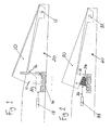
- a first embodiment as illustrated in figure 1, comprises two spaced apart, substantially parallel ramp members 10, which are each pivotally attached by a pivot pin 12 near their rear end to a sloping rear end of a chassis 20 of a towing vehicle (tractor unit).
- a fifth wheel coupling for attachment of a trailer is typically mounted onto the chassis 20 in front of the ramp assembly, but such coupling is not shown here.
- ramp members 10 Only one of the ramp members 10 is shown in figure 1. These ramp members 10 are of downwardly open channel section form and may suitably be connected by a crosspiece (not shown). Respective fluid actuated cylinders 14 (namely pneumatically or hydraulically operated cylinders) are mounted below each of the ramp members 10 with extensible rams or pistons 16 engaging into the channel of the ramp member 10 to raise or lower it. The ramp member 10 is shown in figure 1 in its raised position. The respective cylinders 14 are arranged to operate simultaneously on the respective ramp members 10 to achieve even upward pressure on the pair of ramp members 10.
- Respective fluid actuated cylinders 14 namely pneumatically or hydraulically operated cylinders
- the ramp member 10 is shown in figure 1 in its raised position.
- the respective cylinders 14 are arranged to operate simultaneously on the respective ramp members 10 to achieve even upward pressure on the pair of ramp members 10.
- the fluid actuated cylinders 14, 18 are operated by a central control means of the towing vehicle dependent on input from sensor means (not shown) associated with the fifth wheel coupling to the central control means so that the ramp members 10 will be raised when the coupling is detected to be open (generally indicating that the trailer may be about to be connected or moved away) and lowered when the coupling is detected to be closed (generally indicating that the trailer has been connected and no longer requires guidance on to the rear of the chassis 20).
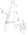
- a second embodiment also comprises two spaced apart, substantially parallel ramp members 30, which are each pivotally attached by a pivot pin 32 near their rear end to a sloping rear end of a chassis 40 of a towing vehicle (tractor unit).
- ramp members 30 may suitably be connected by a crosspiece (not shown).
- Each ramp member 30 may be of downwardly open channel section form for a major part of its length, but with a cross wall connecting between downward extensions 31 at its forward end to provide a bearing surface for a wedge shaped block 34 which is moved to and fro by a transversely mounted fluid actuated cylinder 38 to raise and lower the ramp member 30.
- a piston 36 of the cylinder 38 is extended to push the block 34 towards the rear of the chassis 40 in order to raise the ramp member 30.
- Spring means are provided to assist the return of the ramp member 30 to its lowered condition.
- a helical spring may be provided to act between the ramp member 30 at a position near the extension 31 and the chassis 40.
- a suitable torsion spring may act about the pivot pin 32 to urge the ramp member 30 back to its lowered position.
- respective cylinders 38 and blocks 34 may be provided for each of the ramp members 30 and these should then be operated simultaneously.
- a single cylinder 38 may act on a single block 34 which is wide enough to fit below both of the spaced ramp members 30.
- the control of the cylinder or cylinders 38 is as already described for the first embodiment.
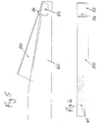
- the third embodiment of ramp assembly is a modified version of the first embodiment shown in figure 1. To avoid repetition, only the modified features are mentioned here and the remainder is the same as already described.
- the respective ramp members are of T-shaped profile, as is evident from figure 4.
- the chassis 20' which may be provided as two separate spaced apart side sections, or may be continuous, extends below the facing, inner sides of the T profiles of the respective ramp members 10', while the cylinder and piston 14', 16' for raising each ramp member 10' is mounted below the remote, outer side of the T profile of each of the ramp members 10'.
- the ramp member 10' is also shown in this embodiment as being angled in longitudinal profile ( Figure 3).
- the arrangement shown in figures 3 and 4 may provide for more streamlined fitting of the ramp assembly into the chassis when in its lowered condition, as depicted in figure 4, and may also allow for easier access to the cylinders 14' for maintenance and repair etc.
- the fourth embodiment of ramp assembly is a modified version of any of the preceding embodiments. To avoid repetition, only the modified features are mentioned here and the remainder is the same as already described.
- the ramp members 50 of which there are two, but only one shown, as before, and which are raised and lowered by any of the means previously described, are not pivotally connected directly to the chassis 60. Instead, they are pivotally connected by hinges 54 to respective additional brackets 52 which are fixed to the rear end of the chassis 60 and which may themselves be considered as part of the overall ramp assembly.
- a single such bracket may be provided as an elongate strip across the rear of the chassis 60.
Landscapes
- Engineering & Computer Science (AREA)
- Transportation (AREA)
- Mechanical Engineering (AREA)
- Chemical & Material Sciences (AREA)
- Combustion & Propulsion (AREA)
- Body Structure For Vehicles (AREA)
- Vehicle Cleaning, Maintenance, Repair, Refitting, And Outriggers (AREA)
- Vehicle Body Suspensions (AREA)
- Valves And Accessory Devices For Braking Systems (AREA)
- Branch Pipes, Bends, And The Like (AREA)
- Materials For Medical Uses (AREA)
Abstract
Description
- This invention concerns a lead on ramp assembly for use on a vehicle in association with a coupling for attachment of a trailer.
- In respect of an articulated lorry, a tractor unit vehicle is provided with a fifth wheel coupling for attachment of a trailer and a lead on ramp is commonly provided behind the coupling (when considered in the direction of travel). Such a lead on ramp typically comprises a pair of spaced apart sloping beams, which may be of channel section steel, connected by a crosspiece.
- The purpose of the lead on ramp is to guide the front of the trailer upwards to facilitate its coupling, more specifically to facilitate engagement of a kingpin dependent from a front region of the trailer into a rearwardly directed slot in the fifth wheel coupling. In the absence of such a ramp, rear mudguards/mud wings of the tractor unit vehicle may be damaged upon trailer coupling, and even the chassis itself may be damaged if the trailer is not correctly aligned as coupling is attempted. However, the presence of the ramp may also cause problems. For example, an articulation angle of 7 degrees in a vertical direction is usually allowed for between the tractor unit and the trailer, but when this is near maximum or is exceeded, e.g. when travelling over steep hills or boarding ferries, the under carriage of the trailer may contact the ramp and either the ramp or the undercarriage may be damaged.
- An object of the invention is to avoid the aforesaid problems.
- With this object in view, the invention provides a lead on ramp assembly for use on a vehicle in association with a coupling for attachment of a trailer, said assembly comprising at least one ramp member having an upper ramp surface and having means for pivotable mounting relative to a chassis of the vehicle so as to be movable between a raised operative condition wherein the upper surface is inclined at a predetermined angle relative to the chassis and a lowered non-operative condition, drive means for moving said ramp member between its raised and lowered conditions, sensor means for detecting an arrangement indicative of attachment of the trailer to the associated coupling and control means operatively connected to both the drive means and the sensor means whereby the drive means is caused to move the ramp member to its lowered condition once the sensor means detects the arrangement indicative of the trailer being attached to the coupling and the drive means is actuated to move the ramp member to its raised condition once the sensor means detects that the arrangement is indicative that the trailer is no longer attached to the coupling.
- The drive means may suitably comprise at least one hydraulic or pneumatic ram. There are various ways in which such a ram or rams may be mounted and operative to raise and lower the ramp. Additional support means for the ramp member in its raised condition may be provided, for example in the form of a displaceable support block.
- The sensor means may conveniently detect whether the coupling is closed or open, the arrangement indicating that the coupling is closed being indicative of attachment of the trailer to the associated coupling, while the arrangement indicating that the coupling is open being indicative of detachment of the trailer from the coupling even though the trailer may not, at that stage, have moved away from the towing vehicle. In this respect, a conventional fifth wheel coupling includes a release arm which engages a coupling plate in two different positions such that it projects further out from the coupling plate when the coupling is open compared to when the coupling is closed, and also at a different angle in these two positions. The sensor may then comprise a proximity switch mounted on the coupling plate adjacent the release arm to detect the position of this release arm. However, in other embodiments, suitable sensor means may be provided adjacent a slot in the fifth wheel coupling in order to detect more directly either the position of a locking bar which opens and closes the slot in the coupling, or the presence of the trailer kingpin in a correct position in the slot for secure coupling of the trailer thereto.
- The invention will be described further, by way of example, with reference to the accompanying drawings, in which:
- Figure 1 is a schematic side view showing how a first embodiment of the ramp assembly of the invention operates;
- Figure 2 is a similar view showing operation of a second embodiment of the assembly of the invention;
- Figure 3 is a similar view of a third embodiment of the assembly of the invention;
- Figure 4 is a schematic transverse cross-section of the ramp assembly shown in figure 3;
- Figure 5 is another schematic side view of a fourth embodiment of the assembly of the invention; and
- Figure 6 is a view from above of the same fourth embodiment of figure 5.
- A first embodiment, as illustrated in figure 1, comprises two spaced apart, substantially
parallel ramp members 10, which are each pivotally attached by apivot pin 12 near their rear end to a sloping rear end of achassis 20 of a towing vehicle (tractor unit). A fifth wheel coupling for attachment of a trailer is typically mounted onto thechassis 20 in front of the ramp assembly, but such coupling is not shown here. - Only one of the
ramp members 10 is shown in figure 1. Theseramp members 10 are of downwardly open channel section form and may suitably be connected by a crosspiece (not shown). Respective fluid actuated cylinders 14 (namely pneumatically or hydraulically operated cylinders) are mounted below each of theramp members 10 with extensible rams orpistons 16 engaging into the channel of theramp member 10 to raise or lower it. Theramp member 10 is shown in figure 1 in its raised position. Therespective cylinders 14 are arranged to operate simultaneously on therespective ramp members 10 to achieve even upward pressure on the pair oframp members 10. - Further fluid actuated
cylinders 18, again one for eachramp member 10, operate to displacerespective support blocks 22 into position below a downward extension 11 at the front of eachramp member 10 once theramp members 10 have been raised. Thesecylinders 18 act in synchrony with thecylinders 14 and act to withdraw thesupport blocks 22 when theramp members 10 are to be lowered again. In a modified version, however, there may be only asingle cylinder 18 acting upon asingle support block 22 which is wide enough to fit below and support both ramp members of the assembly. - The fluid actuated
cylinders ramp members 10 will be raised when the coupling is detected to be open (generally indicating that the trailer may be about to be connected or moved away) and lowered when the coupling is detected to be closed (generally indicating that the trailer has been connected and no longer requires guidance on to the rear of the chassis 20). - A second embodiment, as illustrated in figure 2, also comprises two spaced apart, substantially
parallel ramp members 30, which are each pivotally attached by apivot pin 32 near their rear end to a sloping rear end of achassis 40 of a towing vehicle (tractor unit). Again, only one of theramp members 30 is shown in figure 2 and theseramp members 30 may suitably be connected by a crosspiece (not shown). Eachramp member 30 may be of downwardly open channel section form for a major part of its length, but with a cross wall connecting betweendownward extensions 31 at its forward end to provide a bearing surface for a wedge shapedblock 34 which is moved to and fro by a transversely mounted fluid actuatedcylinder 38 to raise and lower theramp member 30. Apiston 36 of thecylinder 38 is extended to push theblock 34 towards the rear of thechassis 40 in order to raise theramp member 30. - Spring means (not shown) are provided to assist the return of the
ramp member 30 to its lowered condition. Thus, a helical spring may be provided to act between theramp member 30 at a position near theextension 31 and thechassis 40. Alternatively (or additionally) a suitable torsion spring may act about thepivot pin 32 to urge theramp member 30 back to its lowered position. - As with the first embodiment,
respective cylinders 38 andblocks 34 may be provided for each of theramp members 30 and these should then be operated simultaneously. However in a modified version asingle cylinder 38 may act on asingle block 34 which is wide enough to fit below both of the spacedramp members 30. The control of the cylinder orcylinders 38 is as already described for the first embodiment. - The third embodiment of ramp assembly, as illustrated in figures 3 and 4, is a modified version of the first embodiment shown in figure 1. To avoid repetition, only the modified features are mentioned here and the remainder is the same as already described.
- Instead of being in the form of downwardly open channel sections, the respective ramp members, here denoted by reference numeral 10' for the single member which is shown, are of T-shaped profile, as is evident from figure 4. The chassis 20', which may be provided as two separate spaced apart side sections, or may be continuous, extends below the facing, inner sides of the T profiles of the respective ramp members 10', while the cylinder and piston 14', 16' for raising each ramp member 10' is mounted below the remote, outer side of the T profile of each of the ramp members 10'.
- The ramp member 10' is also shown in this embodiment as being angled in longitudinal profile (Figure 3).
- The arrangement shown in figures 3 and 4 may provide for more streamlined fitting of the ramp assembly into the chassis when in its lowered condition, as depicted in figure 4, and may also allow for easier access to the cylinders 14' for maintenance and repair etc.
- The fourth embodiment of ramp assembly, as illustrated in figures 5 and 6, is a modified version of any of the preceding embodiments. To avoid repetition, only the modified features are mentioned here and the remainder is the same as already described. In this embodiment, the
ramp members 50, of which there are two, but only one shown, as before, and which are raised and lowered by any of the means previously described, are not pivotally connected directly to thechassis 60. Instead, they are pivotally connected byhinges 54 to respectiveadditional brackets 52 which are fixed to the rear end of thechassis 60 and which may themselves be considered as part of the overall ramp assembly. In a modified version, a single such bracket may be provided as an elongate strip across the rear of thechassis 60. - The foregoing embodiments are illustrative and not limitative of the scope of the invention and many other variations in the detail of the configuration, mounting and operation of the ramp assembly is possible within the scope of the invention as defined in the claims.
Claims (3)
- A lead on ramp assembly for use on a vehicle in association with a coupling for attachment of a trailer, said assembly comprising at least one ramp member (10; 30; 10'; 50) having an upper ramp surface and having means (12; 32; 12'; 54) for pivotable mounting relative to a chassis (20; 40; 20'; 60) of the vehicle so as to be movable between a raised operative condition wherein the upper surface is inclined at a predetermined angle relative to the chassis and a lowered non-operative condition, drive means (14,16; 34, 36; 14', 16') for moving said ramp member between its raised and lowered conditions, sensor means for detecting attachment of the trailer to the associated coupling and control means operatively connected to both the drive means and the sensor means whereby the drive means is caused to move the ramp member to its lowered condition once the sensor means detects that the trailer is attached to the coupling and the drive means is actuated to move the ramp member to its raised condition once the sensor means detects that the trailer is no longer attached to the coupling.
- A lead on ramp assembly according to claim 1 wherein the drive means comprises at least one hydraulic or pneumatic ram (16; 38; 16').
- A lead on ramp assembly according to claim 1 or 2 wherein additional support means for the ramp member in its raised condition is provided, for example in the form of a displaceable support block (22; 34).
Applications Claiming Priority (1)
| Application Number | Priority Date | Filing Date | Title |
|---|---|---|---|
| GB0609197A GB2437947B (en) | 2006-05-10 | 2006-05-10 | Lead on ramp assembly associated with trailer coupling |
Publications (3)
| Publication Number | Publication Date |
|---|---|
| EP1854709A2 true EP1854709A2 (en) | 2007-11-14 |
| EP1854709A3 EP1854709A3 (en) | 2008-04-16 |
| EP1854709B1 EP1854709B1 (en) | 2009-10-21 |
Family
ID=36637185
Family Applications (1)
| Application Number | Title | Priority Date | Filing Date |
|---|---|---|---|
| EP07251833A Not-in-force EP1854709B1 (en) | 2006-05-10 | 2007-05-01 | Lead on ramp assembly associated with trailer coupling |
Country Status (4)
| Country | Link |
|---|---|
| EP (1) | EP1854709B1 (en) |
| AT (1) | ATE446237T1 (en) |
| DE (1) | DE602007002836D1 (en) |
| GB (1) | GB2437947B (en) |
Families Citing this family (1)
| Publication number | Priority date | Publication date | Assignee | Title |
|---|---|---|---|---|
| GB2532973A (en) * | 2014-12-03 | 2016-06-08 | The Marmon Group Ltd | Lead-on ramp |
Family Cites Families (5)
| Publication number | Priority date | Publication date | Assignee | Title |
|---|---|---|---|---|
| US4143885A (en) * | 1977-07-29 | 1979-03-13 | Mahosky Barry A | Tractor trailer lift rails |
| GB2037684B (en) * | 1978-12-22 | 1982-10-20 | Lyka Cranes Ltd | Tractor vehicles |
| US20020145268A1 (en) * | 2001-04-06 | 2002-10-10 | Zechbauer Carl A. | Trailer hitch guide |
| DE10223612C1 (en) * | 2002-05-27 | 2003-07-03 | Mafi Transport Systeme Gmbh | Tractor vehicle for articulated lorry has saddle plate for hitch arm actuated by lifting jack |
| DE102004021562A1 (en) * | 2004-05-03 | 2005-12-08 | Daimlerchrysler Ag | Method for parking and picking up a semi-trailer |
-
2006
- 2006-05-10 GB GB0609197A patent/GB2437947B/en not_active Expired - Fee Related
-
2007
- 2007-05-01 AT AT07251833T patent/ATE446237T1/en not_active IP Right Cessation
- 2007-05-01 EP EP07251833A patent/EP1854709B1/en not_active Not-in-force
- 2007-05-01 DE DE602007002836T patent/DE602007002836D1/en active Active
Non-Patent Citations (1)
| Title |
|---|
| None |
Also Published As
| Publication number | Publication date |
|---|---|
| GB2437947B (en) | 2010-04-28 |
| ATE446237T1 (en) | 2009-11-15 |
| GB2437947A (en) | 2007-11-14 |
| EP1854709A3 (en) | 2008-04-16 |
| GB0609197D0 (en) | 2006-06-21 |
| EP1854709B1 (en) | 2009-10-21 |
| DE602007002836D1 (en) | 2009-12-03 |
Similar Documents
| Publication | Publication Date | Title |
|---|---|---|
| US8662535B2 (en) | Support frame vehicle restraints | |
| US5896957A (en) | Wheel blocking device | |
| DK180646B1 (en) | System for preventing semitrailer collisions with a loading ramp | |
| US4865507A (en) | Dock leveler assembly and latch mechanism therefor | |
| JP5670425B2 (en) | Method and control system for fifth wheel slider with detection of bent position of towing vehicle and trailer | |
| US3827753A (en) | Vehicle dump body with auxiliary inner movable body | |
| US3667631A (en) | Hydraulic utility lift for trucks | |
| US6311993B1 (en) | Lift axle suspension mounting system | |
| EP2103458B1 (en) | A vehicle hitch | |
| US20080265544A1 (en) | Fifth Wheel Assembly for Coupling a Trailer to a Truck Tractor and a Method for Operating Said Assembly | |
| US7422262B2 (en) | Power operated retractable tailgate assembly | |
| EP1854709B1 (en) | Lead on ramp assembly associated with trailer coupling | |
| EP0151506A1 (en) | A coupling device between a truck and a trailer, provided with a telescopically extendible tow bar | |
| US2968412A (en) | Trailer-tractor | |
| US6769859B2 (en) | Apparatus and method of multi-actuator ejection mechanism | |
| GB2037684A (en) | Improvements in or relating to tractor vehicles | |
| JP3878738B2 (en) | Compost spreader | |
| US20030140526A1 (en) | Universal trailer for a longwall roof support for longwall underground mining | |
| AU2016250434B2 (en) | A vehicle having a ramp arrangement and a ramp arrangement | |
| EP2269868A1 (en) | Wheel-lift assembly for wreckers | |
| ITTO941071A1 (en) | OVERLAPPED VEHICLE FOR THE TRANSPORT OF MOTOR VEHICLES. | |
| JP4070039B2 (en) | Bumper equipment for road work vehicles | |
| CA3231333A1 (en) | Ground-mountable retractable trailer stand system | |
| CA1314576C (en) | Retractable bumper bar | |
| WO2007114721A3 (en) | Mechanism for automatic turning, lifting, lowering and locking the lateral side of the trunk of loading vehicles and trailers |
Legal Events
| Date | Code | Title | Description |
|---|---|---|---|
| PUAI | Public reference made under article 153(3) epc to a published international application that has entered the european phase |
Free format text: ORIGINAL CODE: 0009012 |
|
| AK | Designated contracting states |
Kind code of ref document: A2 Designated state(s): AT BE BG CH CY CZ DE DK EE ES FI FR GB GR HU IE IS IT LI LT LU LV MC MT NL PL PT RO SE SI SK TR |
|
| AX | Request for extension of the european patent |
Extension state: AL BA HR MK YU |
|
| PUAL | Search report despatched |
Free format text: ORIGINAL CODE: 0009013 |
|
| AK | Designated contracting states |
Kind code of ref document: A3 Designated state(s): AT BE BG CH CY CZ DE DK EE ES FI FR GB GR HU IE IS IT LI LT LU LV MC MT NL PL PT RO SE SI SK TR |
|
| AX | Request for extension of the european patent |
Extension state: AL BA HR MK RS |
|
| 17P | Request for examination filed |
Effective date: 20080923 |
|
| AKX | Designation fees paid |
Designated state(s): AT BE BG CH CY CZ DE DK EE ES FI FR GB GR HU IE IS IT LI LT LU LV MC MT NL PL PT RO SE SI SK TR |
|
| GRAP | Despatch of communication of intention to grant a patent |
Free format text: ORIGINAL CODE: EPIDOSNIGR1 |
|
| GRAS | Grant fee paid |
Free format text: ORIGINAL CODE: EPIDOSNIGR3 |
|
| GRAA | (expected) grant |
Free format text: ORIGINAL CODE: 0009210 |
|
| AK | Designated contracting states |
Kind code of ref document: B1 Designated state(s): AT BE BG CH CY CZ DE DK EE ES FI FR GR HU IE IS IT LI LT LU LV MC MT NL PL PT RO SE SI SK TR |
|
| REG | Reference to a national code |
Ref country code: CH Ref legal event code: EP |
|
| REG | Reference to a national code |
Ref country code: IE Ref legal event code: FG4D |
|
| REF | Corresponds to: |
Ref document number: 602007002836 Country of ref document: DE Date of ref document: 20091203 Kind code of ref document: P |
|
| REG | Reference to a national code |
Ref country code: SE Ref legal event code: TRGR |
|
| LTIE | Lt: invalidation of european patent or patent extension |
Effective date: 20091021 |
|
| PG25 | Lapsed in a contracting state [announced via postgrant information from national office to epo] |
Ref country code: FI Free format text: LAPSE BECAUSE OF FAILURE TO SUBMIT A TRANSLATION OF THE DESCRIPTION OR TO PAY THE FEE WITHIN THE PRESCRIBED TIME-LIMIT Effective date: 20091021 Ref country code: PT Free format text: LAPSE BECAUSE OF FAILURE TO SUBMIT A TRANSLATION OF THE DESCRIPTION OR TO PAY THE FEE WITHIN THE PRESCRIBED TIME-LIMIT Effective date: 20100222 Ref country code: IS Free format text: LAPSE BECAUSE OF FAILURE TO SUBMIT A TRANSLATION OF THE DESCRIPTION OR TO PAY THE FEE WITHIN THE PRESCRIBED TIME-LIMIT Effective date: 20100221 Ref country code: LT Free format text: LAPSE BECAUSE OF FAILURE TO SUBMIT A TRANSLATION OF THE DESCRIPTION OR TO PAY THE FEE WITHIN THE PRESCRIBED TIME-LIMIT Effective date: 20091021 Ref country code: ES Free format text: LAPSE BECAUSE OF FAILURE TO SUBMIT A TRANSLATION OF THE DESCRIPTION OR TO PAY THE FEE WITHIN THE PRESCRIBED TIME-LIMIT Effective date: 20100201 |
|
| PG25 | Lapsed in a contracting state [announced via postgrant information from national office to epo] |
Ref country code: SI Free format text: LAPSE BECAUSE OF FAILURE TO SUBMIT A TRANSLATION OF THE DESCRIPTION OR TO PAY THE FEE WITHIN THE PRESCRIBED TIME-LIMIT Effective date: 20091021 Ref country code: PL Free format text: LAPSE BECAUSE OF FAILURE TO SUBMIT A TRANSLATION OF THE DESCRIPTION OR TO PAY THE FEE WITHIN THE PRESCRIBED TIME-LIMIT Effective date: 20091021 Ref country code: LV Free format text: LAPSE BECAUSE OF FAILURE TO SUBMIT A TRANSLATION OF THE DESCRIPTION OR TO PAY THE FEE WITHIN THE PRESCRIBED TIME-LIMIT Effective date: 20091021 |
|
| PG25 | Lapsed in a contracting state [announced via postgrant information from national office to epo] |
Ref country code: AT Free format text: LAPSE BECAUSE OF FAILURE TO SUBMIT A TRANSLATION OF THE DESCRIPTION OR TO PAY THE FEE WITHIN THE PRESCRIBED TIME-LIMIT Effective date: 20091021 Ref country code: BE Free format text: LAPSE BECAUSE OF FAILURE TO SUBMIT A TRANSLATION OF THE DESCRIPTION OR TO PAY THE FEE WITHIN THE PRESCRIBED TIME-LIMIT Effective date: 20091021 |
|
| PG25 | Lapsed in a contracting state [announced via postgrant information from national office to epo] |
Ref country code: BG Free format text: LAPSE BECAUSE OF FAILURE TO SUBMIT A TRANSLATION OF THE DESCRIPTION OR TO PAY THE FEE WITHIN THE PRESCRIBED TIME-LIMIT Effective date: 20100121 Ref country code: DK Free format text: LAPSE BECAUSE OF FAILURE TO SUBMIT A TRANSLATION OF THE DESCRIPTION OR TO PAY THE FEE WITHIN THE PRESCRIBED TIME-LIMIT Effective date: 20091021 Ref country code: RO Free format text: LAPSE BECAUSE OF FAILURE TO SUBMIT A TRANSLATION OF THE DESCRIPTION OR TO PAY THE FEE WITHIN THE PRESCRIBED TIME-LIMIT Effective date: 20091021 Ref country code: EE Free format text: LAPSE BECAUSE OF FAILURE TO SUBMIT A TRANSLATION OF THE DESCRIPTION OR TO PAY THE FEE WITHIN THE PRESCRIBED TIME-LIMIT Effective date: 20091021 |
|
| PLBE | No opposition filed within time limit |
Free format text: ORIGINAL CODE: 0009261 |
|
| STAA | Information on the status of an ep patent application or granted ep patent |
Free format text: STATUS: NO OPPOSITION FILED WITHIN TIME LIMIT |
|
| PG25 | Lapsed in a contracting state [announced via postgrant information from national office to epo] |
Ref country code: CZ Free format text: LAPSE BECAUSE OF FAILURE TO SUBMIT A TRANSLATION OF THE DESCRIPTION OR TO PAY THE FEE WITHIN THE PRESCRIBED TIME-LIMIT Effective date: 20091021 Ref country code: SK Free format text: LAPSE BECAUSE OF FAILURE TO SUBMIT A TRANSLATION OF THE DESCRIPTION OR TO PAY THE FEE WITHIN THE PRESCRIBED TIME-LIMIT Effective date: 20091021 |
|
| 26N | No opposition filed |
Effective date: 20100722 |
|
| PG25 | Lapsed in a contracting state [announced via postgrant information from national office to epo] |
Ref country code: GR Free format text: LAPSE BECAUSE OF FAILURE TO SUBMIT A TRANSLATION OF THE DESCRIPTION OR TO PAY THE FEE WITHIN THE PRESCRIBED TIME-LIMIT Effective date: 20100122 |
|
| PGFP | Annual fee paid to national office [announced via postgrant information from national office to epo] |
Ref country code: SE Payment date: 20100517 Year of fee payment: 4 |
|
| REG | Reference to a national code |
Ref country code: NL Ref legal event code: V1 Effective date: 20101201 |
|
| PG25 | Lapsed in a contracting state [announced via postgrant information from national office to epo] |
Ref country code: MC Free format text: LAPSE BECAUSE OF NON-PAYMENT OF DUE FEES Effective date: 20100531 |
|
| REG | Reference to a national code |
Ref country code: FR Ref legal event code: ST Effective date: 20110131 |
|
| PG25 | Lapsed in a contracting state [announced via postgrant information from national office to epo] |
Ref country code: NL Free format text: LAPSE BECAUSE OF NON-PAYMENT OF DUE FEES Effective date: 20101201 Ref country code: IT Free format text: LAPSE BECAUSE OF FAILURE TO SUBMIT A TRANSLATION OF THE DESCRIPTION OR TO PAY THE FEE WITHIN THE PRESCRIBED TIME-LIMIT Effective date: 20091021 |
|
| PG25 | Lapsed in a contracting state [announced via postgrant information from national office to epo] |
Ref country code: IE Free format text: LAPSE BECAUSE OF NON-PAYMENT OF DUE FEES Effective date: 20100501 Ref country code: MT Free format text: LAPSE BECAUSE OF FAILURE TO SUBMIT A TRANSLATION OF THE DESCRIPTION OR TO PAY THE FEE WITHIN THE PRESCRIBED TIME-LIMIT Effective date: 20091021 |
|
| PG25 | Lapsed in a contracting state [announced via postgrant information from national office to epo] |
Ref country code: FR Free format text: LAPSE BECAUSE OF NON-PAYMENT OF DUE FEES Effective date: 20100531 |
|
| REG | Reference to a national code |
Ref country code: CH Ref legal event code: PL |
|
| REG | Reference to a national code |
Ref country code: SE Ref legal event code: EUG |
|
| PG25 | Lapsed in a contracting state [announced via postgrant information from national office to epo] |
Ref country code: CH Free format text: LAPSE BECAUSE OF NON-PAYMENT OF DUE FEES Effective date: 20110531 Ref country code: LI Free format text: LAPSE BECAUSE OF NON-PAYMENT OF DUE FEES Effective date: 20110531 |
|
| PGFP | Annual fee paid to national office [announced via postgrant information from national office to epo] |
Ref country code: DE Payment date: 20120531 Year of fee payment: 6 |
|
| PG25 | Lapsed in a contracting state [announced via postgrant information from national office to epo] |
Ref country code: CY Free format text: LAPSE BECAUSE OF FAILURE TO SUBMIT A TRANSLATION OF THE DESCRIPTION OR TO PAY THE FEE WITHIN THE PRESCRIBED TIME-LIMIT Effective date: 20091021 |
|
| PG25 | Lapsed in a contracting state [announced via postgrant information from national office to epo] |
Ref country code: LU Free format text: LAPSE BECAUSE OF NON-PAYMENT OF DUE FEES Effective date: 20100501 Ref country code: HU Free format text: LAPSE BECAUSE OF FAILURE TO SUBMIT A TRANSLATION OF THE DESCRIPTION OR TO PAY THE FEE WITHIN THE PRESCRIBED TIME-LIMIT Effective date: 20100422 |
|
| PG25 | Lapsed in a contracting state [announced via postgrant information from national office to epo] |
Ref country code: TR Free format text: LAPSE BECAUSE OF FAILURE TO SUBMIT A TRANSLATION OF THE DESCRIPTION OR TO PAY THE FEE WITHIN THE PRESCRIBED TIME-LIMIT Effective date: 20091021 |
|
| PG25 | Lapsed in a contracting state [announced via postgrant information from national office to epo] |
Ref country code: SE Free format text: LAPSE BECAUSE OF NON-PAYMENT OF DUE FEES Effective date: 20110502 |
|
| PG25 | Lapsed in a contracting state [announced via postgrant information from national office to epo] |
Ref country code: DE Free format text: LAPSE BECAUSE OF NON-PAYMENT OF DUE FEES Effective date: 20131203 |
|
| REG | Reference to a national code |
Ref country code: DE Ref legal event code: R119 Ref document number: 602007002836 Country of ref document: DE Effective date: 20131203 |