EP1854658A2 - Improvements in or relating to seats - Google Patents
Improvements in or relating to seats Download PDFInfo
- Publication number
- EP1854658A2 EP1854658A2 EP07107985A EP07107985A EP1854658A2 EP 1854658 A2 EP1854658 A2 EP 1854658A2 EP 07107985 A EP07107985 A EP 07107985A EP 07107985 A EP07107985 A EP 07107985A EP 1854658 A2 EP1854658 A2 EP 1854658A2
- Authority
- EP
- European Patent Office
- Prior art keywords
- seat
- beam portion
- arm
- frame
- seat cushion
- Prior art date
- Legal status (The legal status is an assumption and is not a legal conclusion. Google has not performed a legal analysis and makes no representation as to the accuracy of the status listed.)
- Granted
Links
- 230000003014 reinforcing effect Effects 0.000 claims description 15
- 238000000034 method Methods 0.000 claims description 7
- 238000003780 insertion Methods 0.000 claims description 6
- 230000037431 insertion Effects 0.000 claims description 6
- 230000007246 mechanism Effects 0.000 description 6
- 230000008901 benefit Effects 0.000 description 5
- 238000013461 design Methods 0.000 description 4
- 230000002093 peripheral effect Effects 0.000 description 4
- 238000010586 diagram Methods 0.000 description 2
- 210000001364 upper extremity Anatomy 0.000 description 2
- 229910000838 Al alloy Inorganic materials 0.000 description 1
- 238000005452 bending Methods 0.000 description 1
- 238000005516 engineering process Methods 0.000 description 1
- 239000000463 material Substances 0.000 description 1
- 238000012986 modification Methods 0.000 description 1
- 230000004048 modification Effects 0.000 description 1
- 238000012545 processing Methods 0.000 description 1
- 230000009467 reduction Effects 0.000 description 1
Images






Classifications
-
- B—PERFORMING OPERATIONS; TRANSPORTING
- B60—VEHICLES IN GENERAL
- B60N—SEATS SPECIALLY ADAPTED FOR VEHICLES; VEHICLE PASSENGER ACCOMMODATION NOT OTHERWISE PROVIDED FOR
- B60N2/00—Seats specially adapted for vehicles; Arrangement or mounting of seats in vehicles
- B60N2/68—Seat frames
- B60N2/686—Panel like structures
-
- B—PERFORMING OPERATIONS; TRANSPORTING
- B60—VEHICLES IN GENERAL
- B60N—SEATS SPECIALLY ADAPTED FOR VEHICLES; VEHICLE PASSENGER ACCOMMODATION NOT OTHERWISE PROVIDED FOR
- B60N2/00—Seats specially adapted for vehicles; Arrangement or mounting of seats in vehicles
- B60N2/24—Seats specially adapted for vehicles; Arrangement or mounting of seats in vehicles for particular purposes or particular vehicles
- B60N2/30—Non-dismountable or dismountable seats storable in a non-use position, e.g. foldable spare seats
- B60N2/3002—Non-dismountable or dismountable seats storable in a non-use position, e.g. foldable spare seats back-rest movements
- B60N2/3004—Non-dismountable or dismountable seats storable in a non-use position, e.g. foldable spare seats back-rest movements by rotation only
- B60N2/3009—Non-dismountable or dismountable seats storable in a non-use position, e.g. foldable spare seats back-rest movements by rotation only about transversal axis
- B60N2/3011—Non-dismountable or dismountable seats storable in a non-use position, e.g. foldable spare seats back-rest movements by rotation only about transversal axis the back-rest being hinged on the cushion, e.g. "portefeuille movement"
-
- B—PERFORMING OPERATIONS; TRANSPORTING
- B60—VEHICLES IN GENERAL
- B60N—SEATS SPECIALLY ADAPTED FOR VEHICLES; VEHICLE PASSENGER ACCOMMODATION NOT OTHERWISE PROVIDED FOR
- B60N2/00—Seats specially adapted for vehicles; Arrangement or mounting of seats in vehicles
- B60N2/24—Seats specially adapted for vehicles; Arrangement or mounting of seats in vehicles for particular purposes or particular vehicles
- B60N2/30—Non-dismountable or dismountable seats storable in a non-use position, e.g. foldable spare seats
- B60N2/3038—Cushion movements
- B60N2/304—Cushion movements by rotation only
- B60N2/3045—Cushion movements by rotation only about transversal axis
- B60N2/305—Cushion movements by rotation only about transversal axis the cushion being hinged on the vehicle frame
-
- B—PERFORMING OPERATIONS; TRANSPORTING
- B60—VEHICLES IN GENERAL
- B60N—SEATS SPECIALLY ADAPTED FOR VEHICLES; VEHICLE PASSENGER ACCOMMODATION NOT OTHERWISE PROVIDED FOR
- B60N2/00—Seats specially adapted for vehicles; Arrangement or mounting of seats in vehicles
- B60N2/24—Seats specially adapted for vehicles; Arrangement or mounting of seats in vehicles for particular purposes or particular vehicles
- B60N2/32—Seats specially adapted for vehicles; Arrangement or mounting of seats in vehicles for particular purposes or particular vehicles convertible for other use
- B60N2/36—Seats specially adapted for vehicles; Arrangement or mounting of seats in vehicles for particular purposes or particular vehicles convertible for other use into a loading platform
- B60N2/366—Seats specially adapted for vehicles; Arrangement or mounting of seats in vehicles for particular purposes or particular vehicles convertible for other use into a loading platform characterised by the locking device
-
- B—PERFORMING OPERATIONS; TRANSPORTING
- B60—VEHICLES IN GENERAL
- B60N—SEATS SPECIALLY ADAPTED FOR VEHICLES; VEHICLE PASSENGER ACCOMMODATION NOT OTHERWISE PROVIDED FOR
- B60N2/00—Seats specially adapted for vehicles; Arrangement or mounting of seats in vehicles
- B60N2/68—Seat frames
- B60N2/682—Joining means
Definitions
- the present invention is concerned generally with improvements in or relating to seats and particularly, but not exclusively, to a seat frame structure for a seat having a seat cushion and a seat back and to a method for connecting the seat and seat frame. Aspects of the invention relate to a structure, to a seat, to a method and to a vehicle.
- a seat back frame is formed in a sheet (panel) shape.
- a peripheral edge portion of the seat back frame is wound up into continuous pipe shape (pipe shape) by a curling processing of the peripheral edge portion.
- the connecting structure between the seat back frame and seat cushion frame is not disclosed in Patent Reference 1.
- the frames are connected to each other.
- the connecting bracket is positioned on the side of the seat back frame and the seat cushion frame, such that the pads and leg members are restricted by the connecting bracket, and other installed parts installed on the seat back frame and seat cushion frame.
- a seat frame structure comprising a seat cushion frame comprising a first beam portion having an internal space in at least one of a left/right side edge portion, a seat back frame comprising a second beam portion having an internal space in at least one of a left/right side edge portion and a connecting bracket comprising a first arm portion inserted into the internal space of the first beam portion and connected to the first beam portion and a second arm portion inserted into the internal space of the second beam portion and connected to the second beam portion, wherein the connecting bracket connects the seat cushion frame to the seat back frame.
- the seat cushion frame comprises a third beam portion having an internal space and forming a rear edge of the seat cushion frame, and wherein the connecting bracket comprises a third arm portion inserted in the internal space of the third beam portion and connected to the third beam portion.
- the structure may comprise a collar set in at least one of the arm portions, a bolt disposed in at least one of the beam portions that corresponds to the at least one of the arm portions having the collar, wherein the bolt goes through the collar and a nut screwed onto the bolt in an outer portion of the at least one of the beam portions.
- the structure may comprise an engagement portion set on at least one of the arm portions and a portioning part set on at least one of the beam portions that corresponds to the at least one of the arm portions having the engagement portion, wherein the portioning part is configured to engage with the engagement portion to position the at least one of the arm portions.
- each beam portion has a square cross-sectional shape.
- the connecting bracket rotatably supports the seat back frame around a pivot along the left/right direction of the seat frame structure, and wherein, on the second beam portion, a notch portion is formed such that interference between the second arm portion and the second beam portion is avoided when the seat back frame is rotated.
- the structure may comprise an opening formed on a rear end of the first beam portion and configured such that the first arm portion is able to be inserted therein and an upper wall notch portion formed on an upper wall of the first beam portion in which the first arm portion is inserted and connected to the opening.
- the structure may comprise an opening formed on the rear end of the first beam portion and configured such that the first arm portion is able to be inserted therein and a notch portion formed on the third beam portion to allow insertion of the third arm portion from a rear side.
- a length of the third arm portion is shorter than a length of the first arm portion.
- the structure may comprise a leg portion supporting the seat cushion frame and a fastening structure that fastens the leg portion and the third arm portion together with the third beam portion.
- the structure may comprise a leg portion attached in the third beam portion near the notch portion, wherein the leg portion supports the seat cushion frame and a reinforcing member that reinforces the periphery of the notch portion in the third beam portion and where the leg portion is attached, wherein the notch portion is covered by the reinforcing member.
- a method for assembling a seat frame structure comprising inserting a first arm portion of a connecting bracket into an internal space of a first beam portion of a seat cushion frame and inserting a second arm portion of the connecting bracket into an internal space of a second beam portion of a seat back frame, wherein the seat cushion frame and the seat back frame are connected by the connecting bracket.
- a seat frame structure comprising a seat cushion frame comprising a first beam portion having an internal space in at least one of a left/right side edge portion, a seat back frame comprising a second beam portion having an internal space in at least one of a left/right side edge portion and means for connecting the internal space of the first beam portion to the internal space of the second beam portion.
- a seat and/or a vehicle comprising a seat frame structure as set out in any of the preceding paragraphs.
- a seat frame structure may include a seat cushion frame, a seat back frame and a connecting bracket connecting the seat cushion frame to the seat back frame.
- the seat cushion frame includes a first beam portion having an internal space in at least one of a left/right side edge portion.
- the seat back frame includes a second beam portion having an internal space in at least one of a left/right side edge portion.
- the connecting bracket includes a first arm portion inserted into the internal space of the first beam portion and connected to the first beam portion and a second arm portion inserted into the internal space of the second beam portion and connected to the second beam portion.
- a seat frame structure and components thereof, is shown in accordance with an embodiment of the present invention.
- the seat frame structure is for the seat of a vehicle. More specifically, the seat frame structure of the rear bench seat for 2-3 persons to sit in a one-box design car body.
- the seat frame structure may be adapted to additional seat designs in other types of car bodies, such as, for example, a cab-forward design car body, without departing from the scope of the present invention.
- the seat frame structure 1 is set in a seat having seat cushion 51 and seat back 52.
- the seat frame structure 1 has seat cushion frame 2 set on seat cushion 51 and seat back frame 3 set on seat back 52.
- the seat cushion frame 2 and seat back frame 3 are connected via a hinge structure 4 and supported via a front leg portion 5 on a vehicle body floor (not shown).
- the entire rear bench seat may be folded so that it can be stored on the back surface side of a front seat (not shown).
- the seat cushion frame 2 and seat back frame 3 may be formed in a nearly rectangular shape with about the same width on the major (longer) side of the rectangles.
- a pad (not shown) may be installed on the seat cushion frame 2 and/or the seat back frame 3.
- the seat cushion frame 2 and seat back frame 3 have a structure that has panel portions 6, 7 and folded portions 8, 9 formed on the peripheral edge portions of the panel portions 6, 7.
- the peripheral edge portion of an aluminum alloy or another foldable base material is bent back to the inner side to form folded portions 8, 9.
- the inner portions of folded portions 8, 9 become panel portions 6, 7.
- the bent-back tip portions of folded portions 8, 9 are welded and bonded to panel portions 6, 7.
- the folded portions 8, 9 may be formed in a square-cross-sectional pipe shape with internal spaces in them.
- the folded portion 8 of seat cushion frame 2 has a front beam portion 8A that forms the front edge portion of seat cushion frame 2, side beam portions 8B as a pair of left/right first beam portions that form a side edge portion of seat cushion frame 2, and a rear beam portion 8C as a third beam portion that forms a rear edge portion of seat cushion frame 2.
- the folded portion 8 is formed around the perimeter of panel portion 6.
- the folded portion 9 of seat back frame 3 has an upper beam portion 9A that forms an upper edge portion of seat back frame 3 and side beam portions 9B as a pair of left/right second beam portions that form a side edge portion of seat back frame 3.
- the folded portion 8 is formed in a]-shape with respect to panel portion 7, leaving a bottom edge portion of the panel portion 7 without a folded portion.
- a first reinforcing member 43 may be set inside the lower portion of side beam portions 9B, as shown in Figure 6.
- the rear beam portion 8C of seat cushion frame 2 may be set with a left/right width equal to or shorter than the opposite surfaces of side beam portions 8B, and may be set behind the pair of left/right side beam portions 8B. With such an arrangement, the rear side of the left/right pair of side beam portions 8B is opened, while rear beam portion 8C is opened on the left/right side surfaces. On the other hand, the left/right pair of side beam portions 9B of seat back frame 3 has the lower side opened.
- the hinge structure 4 includes a left/right pair of connecting brackets 10 that connect seat back frame 3 in a freely rotatable way on seat cushion frame 2 with the seat back frame 3 positioned in a seating position.
- a lock mechanism 11 that locks seat back frame 3 in place may be installed at the seating position. Consequently, by means of connecting brackets 10, the seat is positioned in the seating position.
- connecting bracket 10 may include the following portions: a base portion 12, a first arm portion 13 extending forward from the base portion 12, a second arm portion 14 extending from the base portion 12 obliquely to the rear upper side, and a third arm portion 15 that extends from the base portion 12 to the inner side (right side) of the seat cushion frame 2.
- the first arm portion 13 may be inserted into the interior (internal space) of the side beam portion (the left side beam portion in this specific example) 8B of seat cushion frame 2 and may be fixed on the side beam portion 8B. More specifically, on the first arm portion 13, two collars 16 with their axes aligned across the interior of the side beam portion are set apart and with their respective axes substantially parallel. On the side beam portion 8B, there is a through-hole (not shown) formed through the side beam portion 8B in the left/right direction and connected to collar 16. Then, a nut 18 may be screwed in the outer portion of side beam portion 8B on a bolt 17, which is set through the collar 16 and through side beam portion 8B.
- the collar 16 is held between the inner side surfaces of the left/right pair of the side beam portions 8B, and the first arm portion 13 is fixed on the side beam portion 8B.
- an opening 8Ba is formed on the rear end of the side beam portion 8B.
- the opening 8Ba allows the first arm portion 13 to be inserted into the side beam portion 8B from the rear side.
- the first arm portion 13 is inserted into an upper notch portion 41 formed on the upper wall of the side beam portion 8B.
- the upper wall notch portion 41 is set connected to opening 8Ba of side beam portion 8B.
- the second arm portion 14 is inserted from the lower side to the interior (internal space) of side beam portion 9B of the seat back frame 3, which is supported such that it can rotate around a first spindle 19 as a pivot. More specifically, on second arm portion 14, single collar 20 with left/right as the axial direction is set. On the other hand, on the pair of side walls of side beam portion 9B, through holes (not shown) connected to collar 20 are formed. The first spindle 19 goes through the through holes and collar 20 and through left/right side beam portions 9B, while it is set on the left/right pair of side beam portions 9B.
- the first spindle 19 includes a spindle main body 21 having a female thread formed on its two end portions and a bolt 22 that is inserted through collar 20 and screwed onto the spindle main body 21.
- bushings may be provided between the spindle main body 21 and the side beam portions 9B and between the head portion of bolt 22 and the side beam portions 9B. The bushings allow the first spindle 19 to rotate smoothly with respect to the second arm portion 14.
- a notch portion 28 may be formed on the side beam portions 9B to avoid interference between the side beam portions 9B and the second arm portion 14 when the seat back frame 3 is rotated around the first spindle 19.
- a notch portion 23 for positioning seat back frame 3 at the seating position may be set lower than the collar 20 and the first spindle 19.
- a pin 24 set on the lower end side with respect to first spindle 19 on side beam portion 9B is engaged, and the seat back is positioned in the seating position.
- the pin 24 is set through the side beam portions 9B with the left/right direction as the axial direction of the pin 24.
- a third arm portion 15 may be inserted in the interior (internal space) of the rear beam portion 8C of the seat cushion frame 2.
- the third arm portion 15 may be fixed on the rear beam portion 8C.
- length L1 of the third arm portion 15 may be shorter than length L2 of the first arm portion 13.
- a notch portion 42 may be formed to allow insertion of a third arm portion 15 from the rear side.
- the third arm portion 15 and the first arm portion 13 can be inserted in the rear beam portion 8C and the side beam portion 8B substantially simultaneously.
- a rear leg portion 27, which supports seat cushion frame 2 may be set near notch portion 42 and on the lower side of notch portion 42.
- a second reinforcing member 44 may be provided to reinforce the periphery of notch portion 42 and the portion where rear leg portion 27 in rear beam portion 8C is attached.
- the second reinforcing member 44 may be set while it covers notch portion 42.
- the rear leg portion 27 has a leg main body 27a in a pipe shape and a connecting member 27b connected to the leg main body 27a such that it can rotate with respect to rear beam portion 8C.
- the second reinforcing member 44 is a panel member formed by bending into a]-shape and fit on the rear beam portion 8C. Then, the connecting member of the rear leg portion 27 may be attached on the lower surface of the second reinforcing member 44.
- the third arm portion 15 may be fastened together with the rear leg portion 27 and second reinforcing member 44 by means of a bolt 26 and a nut 45 with respect to the rear beam portion 8C. More specifically, on the third arm portion 15, a collar 25 is formed with the up/down direction as the axial direction. On rear beam portion 8C, an upper/lower pair of first through holes 8Ca for joint fastening is formed through rear beam portion 8C in the up/down direction and is connected to collar 25. Also, on the leg main body 27a of the rear leg portion 27, a second through hole 27c for joint fastening is formed. On second reinforcing member 44, an upper/lower pair of third through holes 44a for joint fastening is formed.
- the bolt 26 passes through the first-third through holes for joint fastening 8Ca, 27c, 44a and collar 25 and through rear beam portion 8C.
- a nut (not shown) may then be screwed onto the outer portion (upper side) of the rear beam portion 8C.
- the third arm portion 15 is held between the upper/lower inner surfaces of the rear beam portion 8C in the portion of collars 16, and while third arm portion 15 is fixed on the rear beam portion 8C, the rear leg portion 27 and the second reinforcing member 44 are fixed on the rear beam portion 8C.
- the bolt 26 and the nut 45 form a fastening structure 46.
- the bolt 26 and the nut 45 may be swapped with each other in the up/down direction.
- the lock mechanism 11 includes a second spindle 31.
- This second spindle 31 is rotatably supported on a left/right pair of connecting brackets 10.
- a hook 32 and a manipulating lever 33 are fixed.
- the second spindle 31 may include the following parts: a left/right pair of collars 37 pivoted on the connecting brackets 10, a spindle main body 38 set between the collars 37 and with nut portions formed at its two ends, a left/right pair of bolts 39 inserted from the outside of the connecting brackets 10 into the collars 37 and screwed on the nut portions of spindle main body 38, respectively.
- a left/right pair of nuts 40 may be provided to fasten the manipulating lever 33 onto bolts 39.
- a hook 32 may be set near and on the inner side of the connecting bracket 10. A left/right pair of hooks 32 is set. On each hook 32, a recess 34 is formed. The recess 34 is engaged with the pin 24 set on the beam portion 9B on the side of seat back frame 3. On the back side of recess 34 of hook 32, a guide portion 36 may be formed.
- each of the coil springs 35 has one end portion fixed on the second spindle 31 and has the other end portion fixed on the connecting bracket 10.
- the second spindle 31 is energized in the direction in which the hook 32 is engaged with pin 24 (hereinafter to be referred to as "engagement direction").
- the manipulating lever 33 is set on each of the left/right two end portions of the second spindle 31 protruding outward from connecting bracket 10. When manipulating lever 33 is manipulated, it is possible to release engagement of the left/right pair of hooks 32 and the pins 24 substantially simultaneously.
- the seat frame structure 1 may be assembled as follows. First, the connecting bracket 10, the seat cushion frame 2, and the seat back frame 3 are provided. Then, the first arm portion 136 of the connecting bracket 10 is inserted in and connected to the interior of the side beam portion 8B of the seat cushion frame 2. The third arm portion 15 of the connecting bracket 10 is inserted in and connected to the rear beam portion 8C of the seat cushion frame 2. The second arm portion 14 of the connecting bracket 10 is inserted in and connected to the interior of side beam portion 9B of seat back frame 3. As a result, seat cushion frame 2 and seat back frame 3 are connected to each other via the connecting bracket 10.
- first arm portion 13 and the second arm portion 14 of connecting bracket 10 By inserting the first arm portion 13 and the second arm portion 14 of connecting bracket 10 the interior (internal space) of the side beam portion 8B of the seat cushion frame 2 and the side beam portion 9B of the seat back frame 3, it is possible to improve the freedom in design of the pad or other installed parts set on the side beam portions 8B of the seat cushion frame 2 and the side beam portions 9B of the seat back frame 3 because the connecting bracket 10 is mostly concealed within the seat cushion frame 2 and the seat back frame 3. Also, if the third arm portion 15 of the connecting bracket 10 is inserted in the interior (internal space) of the rear beam portion 8C of the seat cushion frame 2 and fixed on rear beam portion 8C, it is possible to increase the rigidity and strength of the seat cushion frame 2.
- the first arm portion 13-third arm portion 15 and collars 16, 20, 25 may be respectively set, and the arm portions 13, 14, 15 may be connected to the beam portions 8B, 9B, 8C by the bolts 17, 22, 26 that go through the interior of the collars 16, 20, 25 and through the beam portions 8B, 9B, 8C and the nuts (nut 18 for bolt 17) screwed onto the bolts 17, 22, 26 in the outer portions of beam portions 8B, 9B, 8C.
- a structure for positioning arm portions 13, 14, 15 on beam portions 8B, 9B, 8C is not necessary, which allows for a more simple structure for the beam portions 8B, 9B, 8C.
- beam portions 8A, 8B, 8C, 9A, 9B By forming the beam portions 8A, 8B, 8C, 9A, 9B with a square cross-sectional shape, positioning of the front leg portion 5, the rear leg portion 27, the pads, and other installed parts attached on various beam portions 8A, 8B, 8C, 9A, 9B is easier compared to that of a round cross-sectional shape.
- the seat back frame 3 may be supported such that it can rotate around first spindle 19 in the left/right direction of the seat.
- the notch portion 28 may be formed to avoid interference between the second arm portion 14 of the connecting bracket 10 and the side beam portion 9B when the seat back frame 3 rotates. Consequently, when the seat back frame 3 rotates around the first spindle 19, interference of the side beam portions 9B with the second arm portion 14 can be avoided by notch portion 28.
- opening 8Ba may be formed to allow insertion of the first arm portion 13 of the connecting bracket 10 from the rear side.
- Upper notch portion 41 may be formed and connected to opening 8Ba. Consequently, compared with the case when upper notch portion 41 is not set, the first arm portion 13 of the connecting bracket 10 can be inserted deeper inside the side beam portion 8B of the seat cushion frame 2, which allows for a reduction in the size of the seat frame structure 1.
- the opening 8Ba may be formed to allow insertion of the first arm portion 13 of the connecting bracket 10 from the rear side, and the notch portion 42 may be formed on the rear beam portion 8C of the seat cushion frame 2 so that the third arm portion 15 of the connecting bracket 10 can be inserted from the rear side. Consequently, the third arm portion 15 and the first arm portion 13 can be inserted in the rear beam portion 8C and the side beam portions 8B from the rear side substantially simultaneously.
- length L2 of the first arm portion 13 in the connecting bracket 10 is shorter than length L1 of the third arm portion 15, compared with the case when the length relationship is opposite the aforementioned, it is possible to reduce notch portion 42 for insertion of rear beam portion 8C of seat cushion frame 2.
- the second reinforcing member 44 may reinforce the periphery of the notch portion 42 of the seat cushion frame 2 and the portion where the rear leg portion 27 is attached while it covers the notch portion 42.
- the member for reinforcing the periphery of the notch portion 42 of the rear beam portion 8C, and the member for reinforcing the portion where the rear leg portion 27 is attached on the rear beam portion 8C it is possible to simplify the seat frame structure 1.
- Figure 10 is a horizontal cross-sectional view illustrating the connecting structure between the first arm portion of the connecting bracket and the seat cushion frame.
- Figure 11 is an exploded oblique view illustrating the connecting structure between the first arm portion of the connecting bracket and the seat cushion frame.
- Figure 12 is a diagram illustrating the connecting structure between the first arm portion of the connecting bracket and the seat cushion frame.
- the embodiment shown in Figures 10-12 differs in that the fixing structure of the first arm portion 113 is different from that of the side beam portion 108B of the seat cushion frame 2.
- two positioning pins 141 with the left/right direction as the axial direction are set side-by-side with respect to the front/rear direction.
- the positioning pins 141 are formed in a cylindrical shape.
- Each positioning pin 141 has a flange 142 formed on one end portion. While the positioning pins 141 are inserted into the side beam portion 108B via the through holes 143 formed on one side wall of the side beam portion 108B, the flange 142 is fixed on the outer surface of the side beam portion 108B.
- the positioning pins 141 form a positioning portion 144. Also, the through holes 149 are formed coaxially with the through-holes 143 on the other side wall of the side beam portion 108B.
- two engagement pieces 145 may be set side-by-side in the front/rear direction with the left/right direction taken as the axial direction.
- the engagement pieces 145 form engagement portion 146.
- the engagement pieces 145 may be formed in a curved plate shape with a semi-circular arc cross-sectional shape.
- the engagement piece 145 on the front side is set with the curved inner surface facing forward, while the engagement piece 145 on the rear side is set with the curved inner surface facing upward.
- front and rear notch portions 147, 148 are formed connected to the inner surface of engagement pieces 145.
- the front-side notch portion 147 connected to front-side engagement piece 145 is opened towards the front side, while rear-side notch portion 148 connected to rear-side engagement piece 145 is opened towards the upper side.
- the first arm portion 113 is inserted from the rear side obliquely downward with respect to the side beam portion 108B.
- the inner surface of the front-side engagement piece 145 is in contact with the front-side positioning pin 141, as shown in Figure 12.
- the connecting bracket 10 may be rotated upward around the front-side positioning pin 141.
- the rear-side engagement piece 145 then makes contact with the rear-side positioning pin 141 from the lower side. In this state, the positioning pins 141 of the side beam portion 108B are engaged with the engagement pieces 145 of the first arm portion 113.
- the first arm portion 113 is positioned with respect to the side beam portion 108B by means of the engagement portion 146 and the positioning portion 144. Then, the bolt 150 is inserted via the through-hole 149, the front-side notch portion 147, the rear-side notch portion 148, the positioning pin 141, and the through-hole 149. Then, the nut 151 is screwed onto the bolt 150, so that the first arm portion 113 is fastened on the side beam portion 108B, as shown in Figure 10.
- the present invention is not limited to the above-described embodiments, and various modifications can be made having the benefit of the present disclosure.
- the explanation was with reference to the case of a bench seat for seating of plural persons.
- a seat for a single person may be made in accordance with one or more of the above-described embodiments without departing from the scope of the present invention.
- the present invention is not limited to seats for vehicles.
- the explanation was for examples in which the seat back frame is set by means of the connecting bracket so that it can rotate freely with reference to seat cushion frame.
- one of ordinary skill in the art having benefit of the present disclosure, may also adopt a scheme in which the seat back frame is fixed by the connecting bracket with respect to the seat cushion frame.
- the second arm portion and the connecting bracket may be connected by means of the same connecting structure as that between the first arm portion and the connecting bracket. As a result, in this case, too, connecting bracket enters a state such that the seat is provided in the sitting position.
- the explanation was for examples in which the side beam portions 8B, 108B (first beam portions), the side beam portions 9B (second beam portions), and the connecting brackets are set as a left/right pair.
- one of ordinary skill in the art having benefit of the present disclosure, may also adopt a scheme in which the side beam portion 8B, 108B (first beam portion), the side beam portion 9B (second beam portion), and the connecting bracket 10 are set only on the left side or the right side.
- Figure 13 is a cross-sectional view illustrating the main portion of the connecting structure between the second spindle and the seat back frame in this reference example.
- the second spindle 219 of the lock mechanism 211 is also used as the frame structural member of the seat back frame 203.
- through-holes 204 are formed coaxially.
- the collars 205 are engaged with the through-holes 204.
- the collar 206 is set coaxially with the through-holes 204 and fit between the two side walls.
- the bolt portions 207 are set on the two end portions of the second spindle 219.
- the bolt portions 207 go through the collars 205, 206, 205 and through the side beam portion 209B.
- the nuts 208 are screwed onto the tip portions of the bolt portions 207 so that second spindle 219 is fastened on the side beam portion 209B.
- the connecting bracket 210 is set on the outer side of the seat back frame 203.
- a manipulating lever 233 is provided.
Landscapes
- Engineering & Computer Science (AREA)
- Aviation & Aerospace Engineering (AREA)
- Transportation (AREA)
- Mechanical Engineering (AREA)
- Seats For Vehicles (AREA)
- Chair Legs, Seat Parts, And Backrests (AREA)
Abstract
Description
- The present invention is concerned generally with improvements in or relating to seats and particularly, but not exclusively, to a seat frame structure for a seat having a seat cushion and a seat back and to a method for connecting the seat and seat frame. Aspects of the invention relate to a structure, to a seat, to a method and to a vehicle.
- In the related art, for a seat having a seat back and a seat cushion, especially, for a seat for vehicle use, a seat back frame is formed in a sheet (panel) shape. A peripheral edge portion of the seat back frame is wound up into continuous pipe shape (pipe shape) by a curling processing of the peripheral edge portion. An example is disclosed in Japanese Utility Model Registration
No. 2602770 Patent Reference 1 "). - The connecting structure between the seat back frame and seat cushion frame is not disclosed in
Patent Reference 1. By means of a pair of left/right connecting brackets set along the outer side surface of the seat back frame and the seat cushion frame, the frames are connected to each other. However, for such a connecting structure, the connecting bracket is positioned on the side of the seat back frame and the seat cushion frame, such that the pads and leg members are restricted by the connecting bracket, and other installed parts installed on the seat back frame and seat cushion frame. - It is an aim of the invention to improve upon such known technology. Other aims and advantages of the invention will become apparent from the following description, claims and drawings.
- Aspects of the invention therefore provide a seat, a structure, a method and a vehicle as claimed in the appended claims.
- According to another aspect of the invention there is provided a seat frame structure comprising a seat cushion frame comprising a first beam portion having an internal space in at least one of a left/right side edge portion, a seat back frame comprising a second beam portion having an internal space in at least one of a left/right side edge portion and a connecting bracket comprising a first arm portion inserted into the internal space of the first beam portion and connected to the first beam portion and a second arm portion inserted into the internal space of the second beam portion and connected to the second beam portion, wherein the connecting bracket connects the seat cushion frame to the seat back frame.
- In an embodiment, the seat cushion frame comprises a third beam portion having an internal space and forming a rear edge of the seat cushion frame, and wherein the connecting bracket comprises a third arm portion inserted in the internal space of the third beam portion and connected to the third beam portion.
- The structure may comprise a collar set in at least one of the arm portions, a bolt disposed in at least one of the beam portions that corresponds to the at least one of the arm portions having the collar, wherein the bolt goes through the collar and a nut screwed onto the bolt in an outer portion of the at least one of the beam portions.
- The structure may comprise an engagement portion set on at least one of the arm portions and a portioning part set on at least one of the beam portions that corresponds to the at least one of the arm portions having the engagement portion, wherein the portioning part is configured to engage with the engagement portion to position the at least one of the arm portions.
- In an embodiment, each beam portion has a square cross-sectional shape.
- In an embodiment, the connecting bracket rotatably supports the seat back frame around a pivot along the left/right direction of the seat frame structure, and wherein, on the second beam portion, a notch portion is formed such that interference between the second arm portion and the second beam portion is avoided when the seat back frame is rotated.
- The structure may comprise an opening formed on a rear end of the first beam portion and configured such that the first arm portion is able to be inserted therein and an upper wall notch portion formed on an upper wall of the first beam portion in which the first arm portion is inserted and connected to the opening.
- The structure may comprise an opening formed on the rear end of the first beam portion and configured such that the first arm portion is able to be inserted therein and a notch portion formed on the third beam portion to allow insertion of the third arm portion from a rear side.
- In an embodiment, a length of the third arm portion is shorter than a length of the first arm portion.
- The structure may comprise a leg portion supporting the seat cushion frame and a fastening structure that fastens the leg portion and the third arm portion together with the third beam portion.
- The structure may comprise a leg portion attached in the third beam portion near the notch portion, wherein the leg portion supports the seat cushion frame and a reinforcing member that reinforces the periphery of the notch portion in the third beam portion and where the leg portion is attached, wherein the notch portion is covered by the reinforcing member.
- According to a further aspect of the invention there is provided a method for assembling a seat frame structure, the method comprising inserting a first arm portion of a connecting bracket into an internal space of a first beam portion of a seat cushion frame and inserting a second arm portion of the connecting bracket into an internal space of a second beam portion of a seat back frame, wherein the seat cushion frame and the seat back frame are connected by the connecting bracket.
- According to a still further aspect of the invention there is provided a seat frame structure comprising a seat cushion frame comprising a first beam portion having an internal space in at least one of a left/right side edge portion, a seat back frame comprising a second beam portion having an internal space in at least one of a left/right side edge portion and means for connecting the internal space of the first beam portion to the internal space of the second beam portion.
- According to another aspect of the invention there is provided a seat and/or a vehicle comprising a seat frame structure as set out in any of the preceding paragraphs.
- For example, a seat frame structure may include a seat cushion frame, a seat back frame and a connecting bracket connecting the seat cushion frame to the seat back frame. The seat cushion frame includes a first beam portion having an internal space in at least one of a left/right side edge portion. The seat back frame includes a second beam portion having an internal space in at least one of a left/right side edge portion. The connecting bracket includes a first arm portion inserted into the internal space of the first beam portion and connected to the first beam portion and a second arm portion inserted into the internal space of the second beam portion and connected to the second beam portion.
- Within the scope of this application it is envisaged that the various aspects, embodiments, examples, features and alternatives set out in the preceding paragraphs, in the claims and/or in the following description may be taken individually or in any combination thereof.
- The present invention will now be described, by way of example only, with reference to the accompanying drawings in which:
- Figure 1 is an oblique view illustrating the seat frame structure in accordance with an embodiment of the present invention;
- Figure 2 is an oblique view illustrating an enlarged portion of a connecting structure between the seat cushion frame and the seat back frame shown in Figure 1;
- Figure 3 is an exploded oblique view illustrating an enlarged portion of the connecting structure between the seat cushion frame and the seat back frame shown in Figure 1;
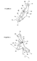
- Figure 4 is an oblique view illustrating an outer surface side of a connecting bracket of the embodiment shown in Figure 1;
- Figure 5 is an oblique view illustrating an inner surface side of the connecting bracket of the embodiment shown in Figure 1;
- Figure 6 is an oblique view as seen from a front side of a lower portion of the seat back frame in the seat frame structure of the embodiment shown in Figure 1;
- Figure 7 is an oblique view as seen from a rear side of a rear corner portion of the seat cushion frame in the seat frame structure of the embodiment shown in Figure 1;
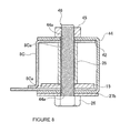
- Figure 8 is a cross-sectional view taken across line VII-VII in Figure 7;
- Figure 9 is an exploded oblique view as seen from a rear side of a portion of the connecting structure between the seat cushion frame and the seat back frame of the
embodiment 1 shown in Figure 1; - Figure 10 is a horizontal cross-sectional view illustrating a connecting structure between a first arm portion of a connecting bracket and a seat cushion frame in accordance with an embodiment of the present invention;
- Figure 11 is an exploded oblique view illustrating the connecting structure between the first arm portion of the connecting bracket and the seat cushion frame of the embodiment shown in Figure 10;
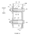
- Figure 12 is a diagram illustrating the connecting structure between the first arm portion of the connecting bracket and the seat cushion frame of the embodiment shown in Figure 10; and
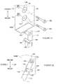
- Figure 13 is a cross-sectional view illustrating a main portion of a connecting structure between a second spindle and the seat back frame in accordance with an embodiment of the present invention.
- In Figures 1-8, a seat frame structure, and components thereof, is shown in accordance with an embodiment of the present invention.. In the embodiment shown in Figures 1-8, the seat frame structure is for the seat of a vehicle. More specifically, the seat frame structure of the rear bench seat for 2-3 persons to sit in a one-box design car body. Those having ordinary skill in the art will appreciate that aspects of the seat frame structure may be adapted to additional seat designs in other types of car bodies, such as, for example, a cab-forward design car body, without departing from the scope of the present invention.
- In the following description, relative directions are used to describe the location and direction of components. As used herein, "forward" and "front" refer to the direction that an occupant of the seat would normally face, and "rearward" and "rear" refer to the opposing direction. "Left/right" refers to a direction perpendicular to the direction that the occupant of the seat would normally face. "Up/down" refers to the vertical direction, with down being towards the occupant's feet and up being towards the occupant's head.
- In Figure 1, the
seat frame structure 1 is set in a seat having seat cushion 51 and seat back 52. Theseat frame structure 1 hasseat cushion frame 2 set on seat cushion 51 andseat back frame 3 set on seat back 52. Theseat cushion frame 2 andseat back frame 3 are connected via a hinge structure 4 and supported via a front leg portion 5 on a vehicle body floor (not shown). In this way, for the rear bench seat havingseat frame structure 1 set on it, when not in use, the entire rear bench seat may be folded so that it can be stored on the back surface side of a front seat (not shown). - The
seat cushion frame 2 andseat back frame 3 may be formed in a nearly rectangular shape with about the same width on the major (longer) side of the rectangles. A pad (not shown) may be installed on theseat cushion frame 2 and/or theseat back frame 3. - The
seat cushion frame 2 andseat back frame 3 have a structure that haspanel portions portions panel portions seat cushion frame 2 andseat back frame 3 with the structure, the peripheral edge portion of an aluminum alloy or another foldable base material is bent back to the inner side to form foldedportions portions panel portions portions panel portions portions - The folded
portion 8 ofseat cushion frame 2 has afront beam portion 8A that forms the front edge portion ofseat cushion frame 2,side beam portions 8B as a pair of left/right first beam portions that form a side edge portion ofseat cushion frame 2, and arear beam portion 8C as a third beam portion that forms a rear edge portion ofseat cushion frame 2. In the embodiment shown in Figure 1, the foldedportion 8 is formed around the perimeter ofpanel portion 6. The foldedportion 9 of seat backframe 3 has anupper beam portion 9A that forms an upper edge portion of seat backframe 3 andside beam portions 9B as a pair of left/right second beam portions that form a side edge portion of seat backframe 3. The foldedportion 8 is formed in a]-shape with respect topanel portion 7, leaving a bottom edge portion of thepanel portion 7 without a folded portion. A first reinforcingmember 43 may be set inside the lower portion ofside beam portions 9B, as shown in Figure 6. - The
rear beam portion 8C ofseat cushion frame 2 may be set with a left/right width equal to or shorter than the opposite surfaces ofside beam portions 8B, and may be set behind the pair of left/rightside beam portions 8B. With such an arrangement, the rear side of the left/right pair ofside beam portions 8B is opened, whilerear beam portion 8C is opened on the left/right side surfaces. On the other hand, the left/right pair ofside beam portions 9B of seat backframe 3 has the lower side opened. - In the following, an explanation will be given regarding the hinge structure 4. As shown in Figure 1, the hinge structure 4 includes a left/right pair of connecting
brackets 10 that connect seat backframe 3 in a freely rotatable way onseat cushion frame 2 with the seat backframe 3 positioned in a seating position. Alock mechanism 11 that locks seat backframe 3 in place may be installed at the seating position. Consequently, by means of connectingbrackets 10, the seat is positioned in the seating position. - Because the left/right pair of connecting
brackets 10 includes planar symmetric parts with respect to a plane perpendicular to a straight line in the left/right direction. With reference to Figures 2-5, a more detailed explanation will be given regarding connectingbracket 10 on the left side as an example. As shown in Figures 2-5, the connectingbracket 10 may include the following portions: abase portion 12, afirst arm portion 13 extending forward from thebase portion 12, asecond arm portion 14 extending from thebase portion 12 obliquely to the rear upper side, and athird arm portion 15 that extends from thebase portion 12 to the inner side (right side) of theseat cushion frame 2. - The
first arm portion 13 may be inserted into the interior (internal space) of the side beam portion (the left side beam portion in this specific example) 8B ofseat cushion frame 2 and may be fixed on theside beam portion 8B. More specifically, on thefirst arm portion 13, twocollars 16 with their axes aligned across the interior of the side beam portion are set apart and with their respective axes substantially parallel. On theside beam portion 8B, there is a through-hole (not shown) formed through theside beam portion 8B in the left/right direction and connected tocollar 16. Then, anut 18 may be screwed in the outer portion ofside beam portion 8B on abolt 17, which is set through thecollar 16 and throughside beam portion 8B. As a result, thecollar 16 is held between the inner side surfaces of the left/right pair of theside beam portions 8B, and thefirst arm portion 13 is fixed on theside beam portion 8B. Here, as shown in Figure 9, on the rear end of theside beam portion 8B, an opening 8Ba is formed. The opening 8Ba allows thefirst arm portion 13 to be inserted into theside beam portion 8B from the rear side. Also, as shown in Figure 2, thefirst arm portion 13 is inserted into anupper notch portion 41 formed on the upper wall of theside beam portion 8B. The upperwall notch portion 41 is set connected to opening 8Ba ofside beam portion 8B. - In the embodiment shown in Figure 2, the
second arm portion 14 is inserted from the lower side to the interior (internal space) ofside beam portion 9B of the seat backframe 3, which is supported such that it can rotate around afirst spindle 19 as a pivot. More specifically, onsecond arm portion 14,single collar 20 with left/right as the axial direction is set. On the other hand, on the pair of side walls ofside beam portion 9B, through holes (not shown) connected tocollar 20 are formed. Thefirst spindle 19 goes through the through holes andcollar 20 and through left/rightside beam portions 9B, while it is set on the left/right pair ofside beam portions 9B. Thefirst spindle 19 includes a spindlemain body 21 having a female thread formed on its two end portions and abolt 22 that is inserted throughcollar 20 and screwed onto the spindlemain body 21. In one embodiment, bushings (not shown) may be provided between the spindlemain body 21 and theside beam portions 9B and between the head portion ofbolt 22 and theside beam portions 9B. The bushings allow thefirst spindle 19 to rotate smoothly with respect to thesecond arm portion 14. Anotch portion 28 may be formed on theside beam portions 9B to avoid interference between theside beam portions 9B and thesecond arm portion 14 when the seat backframe 3 is rotated around thefirst spindle 19. - Turning to Figures 3 and 4, on a
second arm portion 14, anotch portion 23 for positioning seat backframe 3 at the seating position may be set lower than thecollar 20 and thefirst spindle 19. On thenotch portion 23 for positioning, apin 24 set on the lower end side with respect tofirst spindle 19 onside beam portion 9B is engaged, and the seat back is positioned in the seating position. Thepin 24 is set through theside beam portions 9B with the left/right direction as the axial direction of thepin 24. - As shown in Figures 2 and 3, a
third arm portion 15 may be inserted in the interior (internal space) of therear beam portion 8C of theseat cushion frame 2. Thethird arm portion 15 may be fixed on therear beam portion 8C. As shown in Figure 5, length L1 of thethird arm portion 15 may be shorter than length L2 of thefirst arm portion 13. - As shown in Figures 7-9, on the end portion in the left/right direction of
rear beam portion 8C, anotch portion 42 may be formed to allow insertion of athird arm portion 15 from the rear side. As a result, thethird arm portion 15 and thefirst arm portion 13 can be inserted in therear beam portion 8C and theside beam portion 8B substantially simultaneously. Also, onrear beam portion 8C, arear leg portion 27, which supportsseat cushion frame 2, may be set nearnotch portion 42 and on the lower side ofnotch portion 42. Also, onrear beam portion 8C, a second reinforcingmember 44 may be provided to reinforce the periphery ofnotch portion 42 and the portion whererear leg portion 27 inrear beam portion 8C is attached. The second reinforcingmember 44 may be set while it coversnotch portion 42. Therear leg portion 27 has a legmain body 27a in a pipe shape and a connectingmember 27b connected to the legmain body 27a such that it can rotate with respect torear beam portion 8C. In the embodiment shown in Figures 7-9, the second reinforcingmember 44 is a panel member formed by bending into a]-shape and fit on therear beam portion 8C. Then, the connecting member of therear leg portion 27 may be attached on the lower surface of the second reinforcingmember 44. - Continuing with the embodiment shown in Figures 7-9, the
third arm portion 15 may be fastened together with therear leg portion 27 and second reinforcingmember 44 by means of abolt 26 and anut 45 with respect to therear beam portion 8C. More specifically, on thethird arm portion 15, acollar 25 is formed with the up/down direction as the axial direction. Onrear beam portion 8C, an upper/lower pair of first through holes 8Ca for joint fastening is formed throughrear beam portion 8C in the up/down direction and is connected tocollar 25. Also, on the legmain body 27a of therear leg portion 27, a second throughhole 27c for joint fastening is formed. On second reinforcingmember 44, an upper/lower pair of third throughholes 44a for joint fastening is formed. Thebolt 26 passes through the first-third through holes for joint fastening 8Ca, 27c, 44a andcollar 25 and throughrear beam portion 8C. A nut (not shown) may then be screwed onto the outer portion (upper side) of therear beam portion 8C. As a result, thethird arm portion 15 is held between the upper/lower inner surfaces of therear beam portion 8C in the portion ofcollars 16, and whilethird arm portion 15 is fixed on therear beam portion 8C, therear leg portion 27 and the second reinforcingmember 44 are fixed on therear beam portion 8C. Here, thebolt 26 and thenut 45 form afastening structure 46. Also, thebolt 26 and thenut 45 may be swapped with each other in the up/down direction. - In the embodiment shown in Figures 1-3, the
lock mechanism 11 includes asecond spindle 31. Thissecond spindle 31 is rotatably supported on a left/right pair of connectingbrackets 10. On thesecond spindle 31, ahook 32 and a manipulatinglever 33 are fixed. More specifically, thesecond spindle 31 may include the following parts: a left/right pair ofcollars 37 pivoted on the connectingbrackets 10, a spindlemain body 38 set between thecollars 37 and with nut portions formed at its two ends, a left/right pair ofbolts 39 inserted from the outside of the connectingbrackets 10 into thecollars 37 and screwed on the nut portions of spindlemain body 38, respectively. A left/right pair ofnuts 40 may be provided to fasten the manipulatinglever 33 ontobolts 39. - As shown in Figures 2-5, a
hook 32 may be set near and on the inner side of the connectingbracket 10. A left/right pair ofhooks 32 is set. On eachhook 32, arecess 34 is formed. Therecess 34 is engaged with thepin 24 set on thebeam portion 9B on the side of seat backframe 3. On the back side ofrecess 34 ofhook 32, aguide portion 36 may be formed. - On the portion of the
second spindle 31 betweenhook 32 and connectingbracket 10, a left/right pair of coil springs 35 may be inserted from outer side. In this embodiment, each of the coil springs 35 has one end portion fixed on thesecond spindle 31 and has the other end portion fixed on the connectingbracket 10. Thesecond spindle 31 is energized in the direction in which thehook 32 is engaged with pin 24 (hereinafter to be referred to as "engagement direction"). - The manipulating
lever 33 is set on each of the left/right two end portions of thesecond spindle 31 protruding outward from connectingbracket 10. When manipulatinglever 33 is manipulated, it is possible to release engagement of the left/right pair ofhooks 32 and thepins 24 substantially simultaneously. - With the
lock mechanism 11, when the manipulatinglever 33 is manipulated so that thehook 32 is driven to rotate together with thesecond spindle 31 in the direction opposite the engagement direction, engagement of thehook 32 with thepin 24 is released, which allows the seat backframe 3 to fall forward and rotate around thefirst spindle 19. Thehook 32 that is released with respect to thepin 24 is driven to rotate in the engagement direction while it is energized by the coil springs 35. However, by means of a stop mechanism (not shown), further rotation may be stopped in the engagement direction at a predetermined position. Then, while seat backframe 3 is driven to rotate from the forward falling state to the seated position, thepin 24 makes contact with theguide portion 36 of thehook 32, which in turn drives thehook 32 to rotate in the direction opposite the engagement direction. Thepin 24 then moves into therecess 34 of thehook 32. Finally, due to the energizing force of coil springs 35, thepin 24 and therecess 34 ofhook 32 are engaged with each other. As a result, the seat backframe 3 is locked in the seated position. - In one embodiment, the
seat frame structure 1 may be assembled as follows. First, the connectingbracket 10, theseat cushion frame 2, and the seat backframe 3 are provided. Then, the first arm portion 136 of the connectingbracket 10 is inserted in and connected to the interior of theside beam portion 8B of theseat cushion frame 2. Thethird arm portion 15 of the connectingbracket 10 is inserted in and connected to therear beam portion 8C of theseat cushion frame 2. Thesecond arm portion 14 of the connectingbracket 10 is inserted in and connected to the interior ofside beam portion 9B of seat backframe 3. As a result,seat cushion frame 2 and seat backframe 3 are connected to each other via the connectingbracket 10. - By inserting the
first arm portion 13 and thesecond arm portion 14 of connectingbracket 10 the interior (internal space) of theside beam portion 8B of theseat cushion frame 2 and theside beam portion 9B of the seat backframe 3, it is possible to improve the freedom in design of the pad or other installed parts set on theside beam portions 8B of theseat cushion frame 2 and theside beam portions 9B of the seat backframe 3 because the connectingbracket 10 is mostly concealed within theseat cushion frame 2 and the seat backframe 3. Also, if thethird arm portion 15 of the connectingbracket 10 is inserted in the interior (internal space) of therear beam portion 8C of theseat cushion frame 2 and fixed onrear beam portion 8C, it is possible to increase the rigidity and strength of theseat cushion frame 2. As discussed above, the first arm portion 13-third arm portion 15 andcollars arm portions beam portions bolts collars beam portions nut 18 for bolt 17) screwed onto thebolts beam portions arm portions beam portions beam portions - By forming the
beam portions rear leg portion 27, the pads, and other installed parts attached onvarious beam portions - As discussed above, for the connecting
bracket 10, the seat backframe 3 may be supported such that it can rotate aroundfirst spindle 19 in the left/right direction of the seat. Also, on eachside beam portion 9B of the seat backframe 3, thenotch portion 28 may be formed to avoid interference between thesecond arm portion 14 of the connectingbracket 10 and theside beam portion 9B when the seat backframe 3 rotates. Consequently, when the seat backframe 3 rotates around thefirst spindle 19, interference of theside beam portions 9B with thesecond arm portion 14 can be avoided bynotch portion 28. - On the rear end of
side beam portions 8B ofseat cushion frame 2, opening 8Ba may be formed to allow insertion of thefirst arm portion 13 of the connectingbracket 10 from the rear side.Upper notch portion 41 may be formed and connected to opening 8Ba. Consequently, compared with the case whenupper notch portion 41 is not set, thefirst arm portion 13 of the connectingbracket 10 can be inserted deeper inside theside beam portion 8B of theseat cushion frame 2, which allows for a reduction in the size of theseat frame structure 1. - On the rear end of the
side beam portions 8B of theseat cushion frame 2, the opening 8Ba may be formed to allow insertion of thefirst arm portion 13 of the connectingbracket 10 from the rear side, and thenotch portion 42 may be formed on therear beam portion 8C of theseat cushion frame 2 so that thethird arm portion 15 of the connectingbracket 10 can be inserted from the rear side. Consequently, thethird arm portion 15 and thefirst arm portion 13 can be inserted in therear beam portion 8C and theside beam portions 8B from the rear side substantially simultaneously. - In an embodiment in which length L2 of the
first arm portion 13 in the connectingbracket 10 is shorter than length L1 of thethird arm portion 15, compared with the case when the length relationship is opposite the aforementioned, it is possible to reducenotch portion 42 for insertion ofrear beam portion 8C ofseat cushion frame 2. - In an embodiment in which the
rear leg portion 27 and thethird arm portion 15 of the connectingbracket 10 are jointly fastened on rear thebeam portion 8C of theseat cushion frame 2 by means offastening structure 46, compared with the case when therear leg portion 27 and thethird arm portion 15 of the connectingbracket 10 are separately fastened on therear beam portion 8C of theseat cushion frame 2, it is possible to simplify theseat frame structure 1. - As discussed above, the second reinforcing
member 44 may reinforce the periphery of thenotch portion 42 of theseat cushion frame 2 and the portion where therear leg portion 27 is attached while it covers thenotch portion 42. As a result, compared with the case in which individual members are used as the member covering thenotch portion 42, the member for reinforcing the periphery of thenotch portion 42 of therear beam portion 8C, and the member for reinforcing the portion where therear leg portion 27 is attached on therear beam portion 8C, it is possible to simplify theseat frame structure 1. - In the following, with reference to Figures 10-12, an explanation will be given regarding a connecting structure in accordance with another embodiment of the present invention. The same part numbers as those adopted in the embodiments discussed above are adopted, and they will not be explained again. Figure 10 is a horizontal cross-sectional view illustrating the connecting structure between the first arm portion of the connecting bracket and the seat cushion frame. Figure 11 is an exploded oblique view illustrating the connecting structure between the first arm portion of the connecting bracket and the seat cushion frame. Figure 12 is a diagram illustrating the connecting structure between the first arm portion of the connecting bracket and the seat cushion frame.
- Compared to the embodiments described with respect to Figures 1-9, the embodiment shown in Figures 10-12 differs in that the fixing structure of the
first arm portion 113 is different from that of theside beam portion 108B of theseat cushion frame 2. - As shown in Figures 10-12, on the
side beam portion 108B of theseat cushion frame 2, two positioningpins 141 with the left/right direction as the axial direction are set side-by-side with respect to the front/rear direction. The positioning pins 141 are formed in a cylindrical shape. Eachpositioning pin 141 has aflange 142 formed on one end portion. While the positioning pins 141 are inserted into theside beam portion 108B via the throughholes 143 formed on one side wall of theside beam portion 108B, theflange 142 is fixed on the outer surface of theside beam portion 108B. The positioning pins 141 form apositioning portion 144. Also, the throughholes 149 are formed coaxially with the through-holes 143 on the other side wall of theside beam portion 108B. - On the
first arm portion 113 of connectingbracket 10, twoengagement pieces 145 may be set side-by-side in the front/rear direction with the left/right direction taken as the axial direction. Theengagement pieces 145form engagement portion 146. Theengagement pieces 145 may be formed in a curved plate shape with a semi-circular arc cross-sectional shape. Theengagement piece 145 on the front side is set with the curved inner surface facing forward, while theengagement piece 145 on the rear side is set with the curved inner surface facing upward. - On the
first arm portion 113, front andrear notch portions engagement pieces 145. The front-side notch portion 147 connected to front-side engagement piece 145 is opened towards the front side, while rear-side notch portion 148 connected to rear-side engagement piece 145 is opened towards the upper side. - In the following, an explanation will be given regarding the engagement between the positioning pins 141 of the
side beam portion 108B and theengagement pieces 145 of thefirst arm portion 113, including the procedure of their engagement operation. First, thefirst arm portion 113 is inserted from the rear side obliquely downward with respect to theside beam portion 108B. The inner surface of the front-side engagement piece 145 is in contact with the front-side positioning pin 141, as shown in Figure 12. Then, the connectingbracket 10 may be rotated upward around the front-side positioning pin 141. The rear-side engagement piece 145 then makes contact with the rear-side positioning pin 141 from the lower side. In this state, the positioning pins 141 of theside beam portion 108B are engaged with theengagement pieces 145 of thefirst arm portion 113. As a result, thefirst arm portion 113 is positioned with respect to theside beam portion 108B by means of theengagement portion 146 and thepositioning portion 144. Then, thebolt 150 is inserted via the through-hole 149, the front-side notch portion 147, the rear-side notch portion 148, thepositioning pin 141, and the through-hole 149. Then, thenut 151 is screwed onto thebolt 150, so that thefirst arm portion 113 is fastened on theside beam portion 108B, as shown in Figure 10. - In the embodiment shown in Figures 10-12, since the
positioning portion 144 is set monolithically with theside beam portion 108B, positioning of thefirst arm portion 113 with respect to theside beam portion 108B is easily done. - The present invention is not limited to the above-described embodiments, and various modifications can be made having the benefit of the present disclosure. For example, in the above-described embodiments, the explanation was with reference to the case of a bench seat for seating of plural persons. However, those having ordinary skill in the art will appreciate that a seat for a single person may be made in accordance with one or more of the above-described embodiments without departing from the scope of the present invention. Also, the present invention is not limited to seats for vehicles.
- In the above-described embodiments, the explanation was for examples in which the seat back frame is set by means of the connecting bracket so that it can rotate freely with reference to seat cushion frame. However, one of ordinary skill in the art, having benefit of the present disclosure, may also adopt a scheme in which the seat back frame is fixed by the connecting bracket with respect to the seat cushion frame. In such an embodiment, the second arm portion and the connecting bracket may be connected by means of the same connecting structure as that between the first arm portion and the connecting bracket. As a result, in this case, too, connecting bracket enters a state such that the seat is provided in the sitting position.
- In the above-described embodiments, the explanation was for examples in which the
side beam portions side beam portions 9B (second beam portions), and the connecting brackets are set as a left/right pair. However, one of ordinary skill in the art, having benefit of the present disclosure, may also adopt a scheme in which theside beam portion side beam portion 9B (second beam portion), and the connectingbracket 10 are set only on the left side or the right side. - In the following, an explanation will be given regarding a reference example with reference to Figure 13, which is a cross-sectional view illustrating the main portion of the connecting structure between the second spindle and the seat back frame in this reference example.
- In this reference example, the
second spindle 219 of thelock mechanism 211 is also used as the frame structural member of the seat backframe 203. On the left/right side walls of theside beam portion 209B of the seat backframe 203, through-holes 204 are formed coaxially. Thecollars 205 are engaged with the through-holes 204. Also, inside theside beam portion 209B, thecollar 206 is set coaxially with the through-holes 204 and fit between the two side walls. - On the two end portions of the
second spindle 219, thebolt portions 207 are set. Thebolt portions 207 go through thecollars side beam portion 209B. Then, thenuts 208 are screwed onto the tip portions of thebolt portions 207 so thatsecond spindle 219 is fastened on theside beam portion 209B. Also, in the embodiment shown in Figure 13, the connectingbracket 210 is set on the outer side of the seat backframe 203. A manipulatinglever 233 is provided. - In the embodiment shown in Figure 13, since the
second spindle 219 of thelock mechanism 211 is also used as a frame structural member of the seat backframe 203, the structure of seat backframe 203 is simplified and the strength of seat backframe 203 may be increased. - While the invention has been described with respect to a limited number of embodiments, those skilled in the art, having benefit of this disclosure, will appreciate that other embodiments can be devised which do not depart from the scope of the invention as disclosed herein. Accordingly, the scope of the invention should be limited only by the attached claims.
- This application claims priority from
Japanese Patent Application No. 2006-133737, filed 12th May 2006
Claims (11)
- A frame structure for a seat comprising:a seat cushion frame comprising a first beam portion having an internal space in at least one of a left/right side edge portion;a seat back frame comprising a second beam portion having an internal space in at least one of a left/right side edge portion; andmeans for connecting the internal space of the first beam portion to the internal space of the second beam portion.
- A structure as claimed in claim 1 wherein the means for connecting comprises a connecting bracket comprising a first arm portion inserted into the internal space of the first beam portion and connected to the first beam portion and a second arm portion inserted into the internal space of the second beam portion and connected to the second beam portion and wherein the connecting bracket connects the seat cushion frame to the seat back frame.
- A structure as claimed in claim 2 wherein the seat cushion frame comprises a third beam portion having an internal space and forming a rear edge of the seat cushion frame, and wherein the connecting bracket comprises a third arm portion inserted in the internal space of the third beam portion and connected to the third beam portion.
- A structure as claimed in claim 2 or claim 3 comprising::a collar set in at least one of the arm portions;a bolt disposed in at least one of the beam portions that corresponds to the at least one of the arm portions having the collar, wherein the bolt goes through the collar; anda nut screwed onto the bolt in an outer portion of the at least one of the beam portions.
- A structure as claimed in any of claims 2 to 4 comprising:an engagement portion set on at least one of the arm portions, anda portioning part set on at least one of the beam portions that corresponds to the at least one of the arm portions having the engagement portion, wherein the portioning part is arranged to engage with the engagement portion to position the at least one of the arm portions.
- A structure as claimed in any of claims 2 to 5 wherein the connecting bracket rotatably supports the seat back frame around a pivot along the left/right direction of the seat frame structure and wherein, on the second beam portion, a notch portion is formed such that interference between the second arm portion and the second beam portion is avoided when the seat back frame is rotated.
- A structure as claimed in any of claims 2 to 6 comprising:an opening formed on a rear end of the first beam portion and configured such that the first arm portion is able to be inserted therein; and at least one of:an upper wall notch portion formed on an upper wall of the first beam portion in which the first arm portion is inserted and connected to the opening; anda notch portion formed on the third beam portion to allow insertion of the third arm portion from a rear side.
- A structure as claimed in any of claims 2 to 7 comprising:a leg portion supporting the seat cushion frame; anda fastening structure that fastens the leg portion and the third arm portion together with the third beam portion.
- A structure as claimed in any of claims 2 to 8 comprising:a leg portion attached in the third beam portion near the notch portion, wherein the leg portion supports the seat cushion frame; anda reinforcing member that reinforces the periphery of the notch portion in the third beam portion and where the leg portion is attached, wherein the notch portion is covered by the reinforcing member.
- A method for assembling a seat frame structure comprising:inserting a first arm portion of a connecting bracket into an internal space of a first beam portion of a seat cushion frame; andinserting a second arm portion of the connecting bracket into an internal space of a second beam portion of a seat back frame, wherein the seat cushion frame and the seat back frame are connected by the connecting bracket.
- A seat or a vehicle having a structure as claimed in any of claims 1 to 9.
Applications Claiming Priority (1)
| Application Number | Priority Date | Filing Date | Title |
|---|---|---|---|
| JP2006133737 | 2006-05-12 |
Publications (3)
| Publication Number | Publication Date |
|---|---|
| EP1854658A2 true EP1854658A2 (en) | 2007-11-14 |
| EP1854658A3 EP1854658A3 (en) | 2010-03-17 |
| EP1854658B1 EP1854658B1 (en) | 2012-07-18 |
Family
ID=38461910
Family Applications (1)
| Application Number | Title | Priority Date | Filing Date |
|---|---|---|---|
| EP20070107985 Not-in-force EP1854658B1 (en) | 2006-05-12 | 2007-05-11 | Improvements in or relating to seats |
Country Status (2)
| Country | Link |
|---|---|
| EP (1) | EP1854658B1 (en) |
| CN (1) | CN100567046C (en) |
Families Citing this family (4)
| Publication number | Priority date | Publication date | Assignee | Title |
|---|---|---|---|---|
| CN102131671B (en) * | 2008-08-29 | 2018-06-08 | 李尔公司 | Vehicle seat frame and manufacturing method |
| JP4785011B2 (en) * | 2009-08-21 | 2011-10-05 | トヨタ紡織株式会社 | Vehicle seat |
| WO2014027627A1 (en) * | 2012-08-14 | 2014-02-20 | 株式会社デルタツーリング | Vehicle seat |
| JP2022106413A (en) * | 2021-01-07 | 2022-07-20 | トヨタ紡織株式会社 | Seat frame |
Family Cites Families (5)
| Publication number | Priority date | Publication date | Assignee | Title |
|---|---|---|---|---|
| US5238285A (en) * | 1992-07-16 | 1993-08-24 | Douglas & Lomason Company | Folding vehicle bedseat |
| CA2498849C (en) * | 2002-09-20 | 2011-07-26 | Intier Automotive Inc. | Stow in floor seat assembly with main lateral displacement |
| JP3860151B2 (en) * | 2003-08-29 | 2006-12-20 | 株式会社タチエス | Retractable seat for vehicle |
| US7374222B2 (en) * | 2004-04-02 | 2008-05-20 | Intier Automotive Inc. | Fold in floor seat assembly having retracting front leg linkage assembly |
| US7121624B2 (en) * | 2005-01-13 | 2006-10-17 | Fisher Dynamics Corporation | Seat assembly having manual tumble with interlock and powered recline, fold and kneel |
-
2007
- 2007-04-28 CN CNB2007100973044A patent/CN100567046C/en not_active Expired - Fee Related
- 2007-05-11 EP EP20070107985 patent/EP1854658B1/en not_active Not-in-force
Non-Patent Citations (1)
| Title |
|---|
| None |
Also Published As
| Publication number | Publication date |
|---|---|
| EP1854658A3 (en) | 2010-03-17 |
| CN101070057A (en) | 2007-11-14 |
| CN100567046C (en) | 2009-12-09 |
| EP1854658B1 (en) | 2012-07-18 |
Similar Documents
| Publication | Publication Date | Title |
|---|---|---|
| US7959232B2 (en) | Seat frame structure and method for a connecting seat and a seat frame | |
| JP5126481B2 (en) | Split-type seat back opening prevention structure | |
| CN102574484B (en) | Vehicle seat | |
| EP1854658B1 (en) | Improvements in or relating to seats | |
| EP1829736B1 (en) | Automobile seat | |
| JP5882049B2 (en) | Vehicle seat | |
| JP2008265523A (en) | Split-type seat back mounting structure for vehicle seat | |
| JP6822317B2 (en) | Vehicle seat | |
| JP5526719B2 (en) | Vehicle seat device | |
| JP2019085082A (en) | Vehicle seat | |
| JP4924139B2 (en) | Seat belt buckle mounting structure | |
| JP2001225681A (en) | Rear floor structure of car body | |
| JP2018047751A (en) | Vehicular seat | |
| JP4460472B2 (en) | Sheet | |
| JP7740036B2 (en) | Vehicle seats | |
| JP4918867B2 (en) | Vehicle seat | |
| JP5094105B2 (en) | Car seat equipment | |
| JP2007045278A (en) | Front seat lock structure | |
| JP3621309B2 (en) | Car seat reinforcement structure | |
| JP2015209009A (en) | Vehicle seat | |
| JP3621308B2 (en) | Body reinforcement structure around seats in automobiles | |
| JP5503493B2 (en) | Vehicle seat | |
| JP2003252091A (en) | Center hinge structure for vehicle rear seats | |
| JP4300579B2 (en) | Rear seat back for vehicle and mounting method thereof | |
| JP5034523B2 (en) | Vehicle seat |
Legal Events
| Date | Code | Title | Description |
|---|---|---|---|
| PUAI | Public reference made under article 153(3) epc to a published international application that has entered the european phase |
Free format text: ORIGINAL CODE: 0009012 |
|
| AK | Designated contracting states |
Kind code of ref document: A2 Designated state(s): AT BE BG CH CY CZ DE DK EE ES FI FR GB GR HU IE IS IT LI LT LU LV MC MT NL PL PT RO SE SI SK TR |
|
| AX | Request for extension of the european patent |
Extension state: AL BA HR MK YU |
|
| PUAL | Search report despatched |
Free format text: ORIGINAL CODE: 0009013 |
|
| AK | Designated contracting states |
Kind code of ref document: A3 Designated state(s): AT BE BG CH CY CZ DE DK EE ES FI FR GB GR HU IE IS IT LI LT LU LV MC MT NL PL PT RO SE SI SK TR |
|
| AX | Request for extension of the european patent |
Extension state: AL BA HR MK RS |
|
| 17P | Request for examination filed |
Effective date: 20100917 |
|
| 17Q | First examination report despatched |
Effective date: 20101012 |
|
| AKX | Designation fees paid |
Designated state(s): DE FR GB |
|
| GRAP | Despatch of communication of intention to grant a patent |
Free format text: ORIGINAL CODE: EPIDOSNIGR1 |
|
| RIN1 | Information on inventor provided before grant (corrected) |
Inventor name: UDAGAWA, MITSUGU Inventor name: SAWADA, TAMOTSU |
|
| GRAS | Grant fee paid |
Free format text: ORIGINAL CODE: EPIDOSNIGR3 |
|
| GRAA | (expected) grant |
Free format text: ORIGINAL CODE: 0009210 |
|
| AK | Designated contracting states |
Kind code of ref document: B1 Designated state(s): DE FR GB |
|
| REG | Reference to a national code |
Ref country code: GB Ref legal event code: FG4D |
|
| REG | Reference to a national code |
Ref country code: DE Ref legal event code: R096 Ref document number: 602007024041 Country of ref document: DE Effective date: 20120913 |
|
| PLBE | No opposition filed within time limit |
Free format text: ORIGINAL CODE: 0009261 |
|
| STAA | Information on the status of an ep patent application or granted ep patent |
Free format text: STATUS: NO OPPOSITION FILED WITHIN TIME LIMIT |
|
| 26N | No opposition filed |
Effective date: 20130419 |
|
| REG | Reference to a national code |
Ref country code: DE Ref legal event code: R097 Ref document number: 602007024041 Country of ref document: DE Effective date: 20130419 |
|
| REG | Reference to a national code |
Ref country code: FR Ref legal event code: PLFP Year of fee payment: 9 |
|
| PGFP | Annual fee paid to national office [announced via postgrant information from national office to epo] |
Ref country code: GB Payment date: 20150506 Year of fee payment: 9 Ref country code: DE Payment date: 20150506 Year of fee payment: 9 |
|
| PGFP | Annual fee paid to national office [announced via postgrant information from national office to epo] |
Ref country code: FR Payment date: 20150508 Year of fee payment: 9 |
|
| REG | Reference to a national code |
Ref country code: DE Ref legal event code: R119 Ref document number: 602007024041 Country of ref document: DE |
|
| GBPC | Gb: european patent ceased through non-payment of renewal fee |
Effective date: 20160511 |
|
| REG | Reference to a national code |
Ref country code: FR Ref legal event code: ST Effective date: 20170131 |
|
| PG25 | Lapsed in a contracting state [announced via postgrant information from national office to epo] |
Ref country code: FR Free format text: LAPSE BECAUSE OF NON-PAYMENT OF DUE FEES Effective date: 20160531 Ref country code: DE Free format text: LAPSE BECAUSE OF NON-PAYMENT OF DUE FEES Effective date: 20161201 |
|
| PG25 | Lapsed in a contracting state [announced via postgrant information from national office to epo] |
Ref country code: GB Free format text: LAPSE BECAUSE OF NON-PAYMENT OF DUE FEES Effective date: 20160511 |