EP1854575B1 - Electrode tip shaping device - Google Patents
Electrode tip shaping device Download PDFInfo
- Publication number
- EP1854575B1 EP1854575B1 EP06715247.0A EP06715247A EP1854575B1 EP 1854575 B1 EP1854575 B1 EP 1854575B1 EP 06715247 A EP06715247 A EP 06715247A EP 1854575 B1 EP1854575 B1 EP 1854575B1
- Authority
- EP
- European Patent Office
- Prior art keywords
- dressing
- electrode tip
- tools
- dressing tools
- work
- Prior art date
- Legal status (The legal status is an assumption and is not a legal conclusion. Google has not performed a legal analysis and makes no representation as to the accuracy of the status listed.)
- Expired - Lifetime
Links
Images



Classifications
-
- B—PERFORMING OPERATIONS; TRANSPORTING
- B23—MACHINE TOOLS; METAL-WORKING NOT OTHERWISE PROVIDED FOR
- B23K—SOLDERING OR UNSOLDERING; WELDING; CLADDING OR PLATING BY SOLDERING OR WELDING; CUTTING BY APPLYING HEAT LOCALLY, e.g. FLAME CUTTING; WORKING BY LASER BEAM
- B23K11/00—Resistance welding; Severing by resistance heating
- B23K11/30—Features relating to electrodes
- B23K11/3063—Electrode maintenance, e.g. cleaning, grinding
Definitions
- the present invention relates to an electrode tip dressing apparatus according to the preamble of claim 1 as known from JP 2005 014019 which is used for spot welding (resistance welding).
- top electrode tip In a spot welding machine, the top of an electrode tip (hereinafter top electrode tip), when electrified, is exposed to a high temperature under a high pressure. The top electrode tip of the spot welding machine is thus deformed each time the spot welding machine is electrified, which gradually increases the diameter of a flat portion of the top electrode tip.
- spot welding resistance welding
- the diameter of the flat portion of the top electrode tip is increased, current density of the welding current applied to a jointed portion of work is decreased, which makes difficult to form a well-conditioned nugget. Accordingly, the strength of the jointed portion of the work is deteriorated, which eventually lowers product reliability.
- the spot welding (resistance welding) machine each time the top electrode tip is electrified, an amount of the welding current is gradually increased, keeping constant the current density of the welding current applied to the jointed portion of the work.
- This kind of the spot welding machine provided with a step-up function has been generally used. With the spot welding machine, the well-conditioned nugget is continuously obtainable.
- a surface treatment such as galvanization, etc. is often applied to the work.
- a surface treatment material such as zinc melted may adhere to the top electrode tip due to an exoergic heat during the electrification. This may cause adhesion between the work and the top electrode tip.
- the top electrode tip is dressed periodically, for example, in every 50 welding, so that the adhesion between the work and the top electrode tip is prevented.
- the welding gun is made to set at an electrode tip dressing position, so that the top electrode tip is dressed by means of an electrode tip dressing apparatus.
- This type of the dressing is conducted by: driving rotatively a dressing tool of the electrode tip dressing apparatus (see, for example, Patent Document 1) with an electric motor; pressing a pair of the top electrode tip to the dressing tool; and cutting the top electrode tip with the dressing tool.
- the top electrode tip needs to be cut for at least 0.2 mm. Further, in order to ensure a certain welding quality in a spot welding (resistance welding), it is recommendable to dress (cut) the top electrode tip in every single work. Accordingly, to obtain the welding quality, if 40 works are conducted, or the top electrode tip is cut for 8 mm, the electrode tip needs to be exchanged. This not only notably lowers productivity but also increases cost.
- Fig. 9 there has been an electrode tip dressing apparatus 1 wherein dressing tools 2 are exchanged from a cutting type to a plastic-deformation type.
- this electrode tip dressing apparatus 1 while contacting top of an electrode tip (hereinafter top electrode tip) to the dressing tools 2, the dressing tools 2 are rotated around the electrode tip, whereby the top electrode tip is plastically deformed and dressed to a given form.
- JP 2005 014019 on which the precharacterising portion of claim 1 is based, aims to provide a detecting structure and a detecting method of the poor adjustment of the shape of an electrode tip for detecting the poor adjustment of the shape of the electrode tip with high accuracy.
- Vibration generated with a device for adjusting the shape of an electrode tip when adjusting the shape of the electrode tip is detected with a vibration sensor 5 (vibration detecting means) which is mounted on the shape adjusting device of the electrode tip the quality of the shape adjustment of the electrode tip is decided with a deciding device 6 (the deciding means of the quality of the shape adjustment) of the quality of the shape adjustment on the basis of the detected signal of the vibration sensor 5.
- the shape adjusting state of the electrode tip is decided as No Good, the poor shape adjustment of the electrode tip is detected. Then, the principle of measurement is simple, reliability is high and also the poor shape adjustment of the electrode tip is detected with high accuracy. electrode tip dressing tool for the electrode tip dressing apparatus.
- US-B-4,762,446 and US-B1-6,499,921 disclose cutting type electrode-tip-dressers.
- the cutters are all identical and have a constant cutting angle of 30 degrees.
- one of the cutters is extended further towards the centre than the others to cut the centre of the electrode tip.
- the present invention has been made in the light of the above problem, and a first object of the present invention is to provide an electrode tip dressing apparatus, which is miniaturised by reducing a rotational driving-force of a dressing tool. Further, a second object of the present invention is to provide an electrode tip dressing tool for the electrode tip dressing apparatus.
- the present invention provides an electrode tip dressing apparatus as defined in independent claim 1.
- the electrode tip dressing apparatus constitutes a feature of that each of the dressing tools with the dressing portion in an identical form is evenly arranged around the rotational center of the dressing tools; and a contact width in which the top of the electrode tip abuts to the dressing portion is adjusted so that an amount of dressing work, in which the dressing tools conduct to the top of the electrode tip, becomes constant at the whole area of the dressing portion, from the rotational center of the dressing tools to the outer side of the dressing tools.
- the electrode tip dressing apparatus constitutes a feature of that the electrode tip dressing apparatus includes: main dressing tools by which the top of the electrode tip is dressed from the center of the electrode tip to the outer side of the electrode tip; and adjusted dressing tools arranged so as to offset an amount of deviated dressing work done with the main dressing tools.
- the present invention constitutes a feature of that there is provided an electrode tip dressing tool, in which dressing tools are radially arranged in an electrode tip dressing apparatus, and are rotated around an electrode tip while the top of the electrode tip is pressed against a dressing portion of each of the dressing tools; and the top of the electrode tip and the dressing portion are relatively displaced so that the top of the electrode tip is plastically deformed into a given form, wherein a contact width, in which the top of the electrode tip abuts to the dressing portion, is adjusted so that an amount of dressing work conducted to the top of the electrode tip becomes constant at the whole area of the dressing portion, from the rotational center of the dressing tools to the outer side of the dressing tools.
- an excess amount of dressing work in dressing is decreased, so that a rotational driving power of dressing tools can be reduced.
- an amount of dressing work done with dressing tools can be constant on the whole area of dressing portions, so that an excess amount of dressing work in dressing is decreased, resulting in reduction of a rotational driving power of the dressing tools.
- an amount of dressing work done with dressing tools can be constant on the whole area of dressing portions, so that an excess amount of dressing work in dressing is decreased, resulting in reduction of a rotational driving power of the dressing tools.
- the present invention can provide an electrode tip dressing apparatus successfully miniaturized by reducing the rotational driving-force of the dressing tool.
- an electrode tip dressing apparatus 1 is provided with a dressing tool holder 3 wherein pluralities of dressing tools 2 (4 tools in this embodiment) are arranged in a radial direction.
- a top portion of electrode tip 5 hereinafter top electrode tip 5
- the dressing tool holder 3 is driven to rotate around the electrode tip 6.
- the top electrode tip 5 is thus moved relative to the dressing portion 4 of each of the dressing tools 2, whereby the top electrode tip 5 is plastically deformed so as to be dressed into a given form.
- the electrode tip dressing apparatus 1 is provided with a frame 7 formed approximately into E-shape, and a pair of guide rails 10 is provided between a top plate 8 and a bottom plate 9 of the frame 7 in such a manner that each of the guide rails 10 is arranged parallel to each other. Accordingly, in the electrode tip dressing apparatus 1, a dressing head 11 is guidable in a downward direction (in Fig. 2 ) by means of the pair of the guide rails 10; at the tip portion of the dressing head 11, the dressing tool holder 3 is rotatively provided.
- the dressing head 11 is provided with a motor 12 for driving dressing tools.
- the dressing tool holder 3 is driven to rotate via a reduction mechanism by means of the motor 12; each of the dressing tools 2 is thus rotated.
- the pair of the guide rails 10 is provided with compression springs 13. By shifting the dressing head 11 along the guide rails 10, each of the compression springs 13 is compressed and stretched, thereby enabling to absorb impact when the top electrode tip 5 abuts to each of the dressing tools 2.
- the dressing tool holder 3 is formed into approximately cylindrical shape and is also provided with a conical hole 14 (see Fig. 1 ) with an identical shaft center relative to the dressing tool holder 3.
- pluralities of dressing tool-housings 15 (4 tool-housings in this embodiment), which house the dressing tools 2, are arranged evenly around the shaft center of the dressing tool holder 3.
- the dressing tools 2 are made of rigid wear-resisting materials, and as shown in Fig. 1 , by housing each of the dressing tools 2 within the respective dressing tool housing 15 of the dressing tool holder 3, the dressing portions 4 abutted to the top electrode tip 5 are radially arranged, extending from the center of the dressing tool holder 3 (rotation center of the dressing tools 2) to the outer side thereof. Moreover, as shown in Fig. 4 , the dressing portions 4 of the dressing tools 2 are formed into a curved surface.
- a contact width wherein the top electrode tip 5 abuts to the dressing portions 4 is adjusted from the center of the electrode tip 6 to the outer side thereof. Accordingly, the amount of the dressing work done by the dressing tool 2 is made to be constant on the whole area of the dressing portion 4.
- a peak value P1 which shows an amount of dressing work in the dressing portions 4, is placed approximately at center from the rotational center of the dressing tools 2 to the outer side thereof.
- a certain range of the curvature radius R2 is made smaller.
- the amount of the dressing work done with the dressing tools 2 becomes constant at the whole area of the dressing portions 4 from the rotational center of the dressing tools 2 to the outer side thereof.
- the top electrode tip 5 through applied pressure of spot welding (resistance welding), is pressed to each of the dressing tools 2 fitted into the dressing tool holder 3 of the dressing head 11.
- each of the dressing tools 2 is made to rotate around the electrode tip 6, conducting a relative displacement between the top electrode tip 5 and the dressing portion 4 of each of the dressing tools 2.
- friction energy (equal to an amount of the dressing work in which the dressing tool 2 conducts to the top electrode tip 5) occurs between the top electrode tip 5 and the dressing portion 4 of each of the dressing tools 2. With the friction energy, the top electrode tip 5 is plastically deformed into a given form.
- the contact width between the top electrode tip 5 and the dressing portion 4 of each of the dressing tools 2 is adjusted. Accordingly, as shown in Fig. 5 , the amount of the dressing work done with each of the dressing tools 2 becomes constant at the whole area of the dressing portion 4, from the rotational center of the dressing tool 2 to the outer side thereof. An excess amount of the dressing work (amount of the dressing work in which the dressing tool 2 conducts to the top electrode tip 5) is reduced, and the top electrode tip 5 can be plastically deformed into a given form with the minimal amount of the dressing work.
- the curvature radius of the dressing portion 4 of each of the dressing tools 2 is adjusted, whereby the contact width between the top electrode tip 5 and the dressing portion 4 of each of the dressing tools 2 is favorably adjusted, from the rotational center of the dressing tool 2 to the outer side thereof.
- the amount of the dressing work done with each of the dressing tools 2 becomes constant at the whole area of the dressing portion 4, from the rotational center of the dressing tool 2 to the outer side thereof.
- the electrode tip dressing apparatus 1 of the present invention an excess amount of the dressing work, which brings decline of productivity, can be avoided, thus enabling to dress the top electrode tip 5 with the minimal amount of the dressing work. Further, it is possible to reduce a rotational driving power of the dressing tools 2, enabling to labor-save or miniaturize the motor 12 for driving dressing tools as well as the electrode tip dressing apparatus 1.
- the electrode tip dressing apparatus 1 may be constructed in such a manner that a curvature radius of each of dressing portions 4 is made to gradually decrease from the rotational center of dressing tools 2 to the outer side thereof (R5> R6> R7 in Fig. 7 ), and the dressing tools 2 are radially arranged.
- the amount of dressing work done with the dressing tools 2 becomes constant at the whole area of the dressing portion 4, from the rotational center of the dressing tools 2 to the outer side thereof.
- an excess amount of the dressing work which brings decline of productivity, can be avoided thereby enabling to dress the top electrode tip 5 with the minimal amount of the dressing work.
- the electrode tip dressing apparatus 1 of the present invention may be configured with main dressing tools 2a by which a top electrode tip 5 is dressed from the center of an electrode tip 6 to the outside thereof; and adjusted dressing tools 2b placed to be deviated toward the rotational center of the dressing tools 2 so as to offset the amount of the deviated dressing work done with the main dressing tools 2a.
- the dressing tools 2 composed of the main dressing tools 2a and the adjusted dressings tools 2b are radially arranged.
- the amount of the deviated dressing work done with dressing portions 4 of the main dressing tools 2a can be adjusted with the adjusted dressing tools 2b.
- the amount of the dressing work done with the dressing tools 2 is made to be constant at the whole area of the dressing portions 4, from the rotational center of the dressing tools 2 to the outer side thereof. Accordingly, in comparison with the conventional electrode tip dressing apparatus 1, an excess amount of the dressing work, which brings decline of productivity, can be avoided thereby enabling to dress the top electrode tip 5 with the minimal amount of the dressing work. It is also possible to reduce a rotational driving power of the dressing tools 2, enabling to labor-save or miniaturize a motor 12 for driving dressing tools as well as the electrode tip dressing apparatus 1.
Landscapes
- Engineering & Computer Science (AREA)
- Mechanical Engineering (AREA)
- Resistance Welding (AREA)
- Electrical Discharge Machining, Electrochemical Machining, And Combined Machining (AREA)
- Primary Cells (AREA)
- Milling Processes (AREA)
- Grinding-Machine Dressing And Accessory Apparatuses (AREA)
Description
- The present invention relates to an electrode tip dressing apparatus according to the preamble of
claim 1 as known fromJP 2005 014019 - In a spot welding machine, the top of an electrode tip (hereinafter top electrode tip), when electrified, is exposed to a high temperature under a high pressure. The top electrode tip of the spot welding machine is thus deformed each time the spot welding machine is electrified, which gradually increases the diameter of a flat portion of the top electrode tip. In the spot welding (resistance welding), on condition that status such as a welding current, etc. is fixed, if the diameter of the flat portion of the top electrode tip is increased, current density of the welding current applied to a jointed portion of work is decreased, which makes difficult to form a well-conditioned nugget. Accordingly, the strength of the jointed portion of the work is deteriorated, which eventually lowers product reliability. Therefore, in the spot welding (resistance welding) machine, each time the top electrode tip is electrified, an amount of the welding current is gradually increased, keeping constant the current density of the welding current applied to the jointed portion of the work. This kind of the spot welding machine provided with a step-up function has been generally used. With the spot welding machine, the well-conditioned nugget is continuously obtainable.
- However, in the spot welding (resistance welding), a surface treatment such as galvanization, etc. is often applied to the work. In case the spot welding is continuously applied to the work under the surface treatment, a surface treatment material such as zinc melted may adhere to the top electrode tip due to an exoergic heat during the electrification. This may cause adhesion between the work and the top electrode tip. Thus, the top electrode tip is dressed periodically, for example, in every 50 welding, so that the adhesion between the work and the top electrode tip is prevented. In general, in a welding robot provided with a spot welding gun, each time a given number of welding is completed, the welding gun is made to set at an electrode tip dressing position, so that the top electrode tip is dressed by means of an electrode tip dressing apparatus. This type of the dressing is conducted by: driving rotatively a dressing tool of the electrode tip dressing apparatus (see, for example, Patent Document 1) with an electric motor; pressing a pair of the top electrode tip to the dressing tool; and cutting the top electrode tip with the dressing tool.
- Now, in the electrode tip dressing apparatus, for cutting and finishing the top electrode tip in a good manner, the top electrode tip needs to be cut for at least 0.2 mm. Further, in order to ensure a certain welding quality in a spot welding (resistance welding), it is recommendable to dress (cut) the top electrode tip in every single work. Accordingly, to obtain the welding quality, if 40 works are conducted, or the top electrode tip is cut for 8 mm, the electrode tip needs to be exchanged. This not only notably lowers productivity but also increases cost. Thus, as shown in
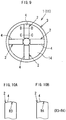
Fig. 9 , there has been an electrodetip dressing apparatus 1 whereindressing tools 2 are exchanged from a cutting type to a plastic-deformation type. In this electrodetip dressing apparatus 1, while contacting top of an electrode tip (hereinafter top electrode tip) to thedressing tools 2, thedressing tools 2 are rotated around the electrode tip, whereby the top electrode tip is plastically deformed and dressed to a given form. - However, in this type of the electrode
tip dressing apparatus 1, even if a contact pressure between the top electrode tip and adressing portion 4 of each of thedressing tools 2 is made uniform, there occurs a different circumferential speed between a rotational center of thedressing tools 2 and an outer side thereof. Since a relative traveling speed to the top electrode tip is different between the rotational center of thedressing tools 2 and the outer side thereof, the dressing done with thedressing tools 2 is not constant. In the conventional electrode tip dressing tool, the outer rotational side of thedressing tools 2 is subject to an excess amount of work, thus increasing a rotational driving-force of thedressing tools 2. Therefore, a larger electric motor to drive thedressing tools 2 is required, thereby making the electrodetip dressing apparatus 1 eventually larger.
Patent Document 1: Japanese Patent Application Laid-open No.H11-77331 -
JP 2005 014019 claim 1 is based, aims to provide a detecting structure and a detecting method of the poor adjustment of the shape of an electrode tip for detecting the poor adjustment of the shape of the electrode tip with high accuracy. Vibration generated with a device for adjusting the shape of an electrode tip when adjusting the shape of the electrode tip is detected with a vibration sensor 5 (vibration detecting means) which is mounted on the shape adjusting device of the electrode tip, the quality of the shape adjustment of the electrode tip is decided with a deciding device 6 (the deciding means of the quality of the shape adjustment) of the quality of the shape adjustment on the basis of the detected signal of thevibration sensor 5. In the case the shape adjusting state of the electrode tip is decided as No Good, the poor shape adjustment of the electrode tip is detected. Then, the principle of measurement is simple, reliability is high and also the poor shape adjustment of the electrode tip is detected with high accuracy. electrode tip dressing tool for the electrode tip dressing apparatus. -
US-B-4,762,446 andUS-B1-6,499,921 disclose cutting type electrode-tip-dressers. InUS-B-4,762,446 the cutters are all identical and have a constant cutting angle of 30 degrees. InUS-B1-6,499,921 one of the cutters is extended further towards the centre than the others to cut the centre of the electrode tip. - The present invention has been made in the light of the above problem, and a first object of the present invention is to provide an electrode tip dressing apparatus, which is miniaturised by reducing a rotational driving-force of a dressing tool. Further, a second object of the present invention is to provide an electrode tip dressing tool for the electrode tip dressing apparatus.
- In order to achieve the object described above, the present invention provides an electrode tip dressing apparatus as defined in
independent claim 1. - According to the invention the electrode tip dressing apparatus constitutes a feature of that each of the dressing tools with the dressing portion in an identical form is evenly arranged around the rotational center of the dressing tools; and a contact width in which the top of the electrode tip abuts to the dressing portion is adjusted so that an amount of dressing work, in which the dressing tools conduct to the top of the electrode tip, becomes constant at the whole area of the dressing portion, from the rotational center of the dressing tools to the outer side of the dressing tools.
- According to the invention the electrode tip dressing apparatus constitutes a feature of that the electrode tip dressing apparatus includes: main dressing tools by which the top of the electrode tip is dressed from the center of the electrode tip to the outer side of the electrode tip; and adjusted dressing tools arranged so as to offset an amount of deviated dressing work done with the main dressing tools.
- In order to achieve the object described above, the present invention constitutes a feature of that there is provided an electrode tip dressing tool, in which dressing tools are radially arranged in an electrode tip dressing apparatus, and are rotated around an electrode tip while the top of the electrode tip is pressed against a dressing portion of each of the dressing tools; and the top of the electrode tip and the dressing portion are relatively displaced so that the top of the electrode tip is plastically deformed into a given form, wherein a contact width, in which the top of the electrode tip abuts to the dressing portion, is adjusted so that an amount of dressing work conducted to the top of the electrode tip becomes constant at the whole area of the dressing portion, from the rotational center of the dressing tools to the outer side of the dressing tools.
- Accordingly, in the invention recited in
claim 1, an excess amount of dressing work in dressing is decreased, so that a rotational driving power of dressing tools can be reduced. - In the invention according to
claim 2, an amount of dressing work done with dressing tools can be constant on the whole area of dressing portions, so that an excess amount of dressing work in dressing is decreased, resulting in reduction of a rotational driving power of the dressing tools. - In the invention according to
claim 3, by optionally setting shape and arrangement of adjusted dressing tools (length and contact width), an amount of dressing work done with dressing tools can be constant on the whole area of dressing portions, so that an excess amount of dressing work in dressing is decreased, resulting in reduction of a rotational driving power of the dressing tools. - The present invention can provide an electrode tip dressing apparatus successfully miniaturized by reducing the rotational driving-force of the dressing tool.
-
-
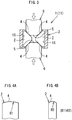
Fig. 1 is an explanatory view of an electrode tip dressing apparatus according to an embodiment of the present invention, which shows dressing tools arranged in a dressing head; -
Fig. 2 is a perspective view of the electrode tip dressing apparatus according to an embodiment of the present invention; -
Fig. 3 is an explanatory view of the electrode tip dressing apparatus according to an embodiment of the present invention, which shows a condition of dressing; -
Fig. 4 is an explanatory view of the electrode tip dressing apparatus according to an embodiment of the present invention, whereinFig. 4A is a magnified view of a section taken along the line A-A ofFig. 1 , andFig. 4B is also a magnified view of a section taken along the line B-B ofFig. 1 ; -
Fig. 5 is an explanatory view showing a relation between a distance from a rotational center of each of the dressing tools and an amount of dressing work based on the present invention and a conventional example; -
Fig. 6 is an explanatory view of the electrode tip dressing apparatus according to another embodiment of the present invention, which shows dressing tools arranged in a dressing head; -
Fig. 7 is an explanatory view of the electrode tip dressing apparatus according to another embodiment of the present invention, whereinFig. 7A is a magnified view of a section taken along the line E-E ofFig. 6 ,Fig. 7B is a magnified view of a section taken along the line F-F ofFig. 6 , andFig. 7C is a magnified view of a section taken along the line G-G ofFig. 6 ; -
Fig. 8 is an explanatory view of the electrode tip dressing apparatus according to still another embodiment of the present invention, which shows dressing tools arranged in a dressing head; -
Fig. 9 is an explanatory view of a conventional electrode tip dressing apparatus, which shows dressing tools arranged in a dressing head; and -
Fig. 10 is an explanatory view of a conventional electrode tip dressing apparatus, whereinFig. 10A is a magnified view of a section taken along the line C-C ofFig. 9, and Fig. 10B is a magnified view of a section taken along the line D-D ofFig. 9 . -
- 1.
- Electrode tip dressing apparatus
- 2.
- Dressing tool
- 4.
- Dressing portion
- 5.
- Top of Electrode tip
- 6.
- Electrode tip
- A first preferred embodiment of the present invention will be described with reference to
figures 1 to 5 . As shown inFig. 1 , an electrodetip dressing apparatus 1 is provided with adressing tool holder 3 wherein pluralities of dressing tools 2 (4 tools in this embodiment) are arranged in a radial direction. In condition that a top portion of electrode tip 5 (hereinafter top electrode tip 5) of anelectrode tip 6 is made to abut to adressing portion 4 of each of thedressing tools 2, the dressingtool holder 3 is driven to rotate around theelectrode tip 6. Thetop electrode tip 5 is thus moved relative to the dressingportion 4 of each of thedressing tools 2, whereby thetop electrode tip 5 is plastically deformed so as to be dressed into a given form. Further, as shown inFig. 2 , the electrodetip dressing apparatus 1 is provided with aframe 7 formed approximately into E-shape, and a pair ofguide rails 10 is provided between atop plate 8 and abottom plate 9 of theframe 7 in such a manner that each of the guide rails 10 is arranged parallel to each other. Accordingly, in the electrodetip dressing apparatus 1, a dressinghead 11 is guidable in a downward direction (inFig. 2 ) by means of the pair of the guide rails 10; at the tip portion of the dressinghead 11, the dressingtool holder 3 is rotatively provided. - Furthermore, in the electrode
tip dressing apparatus 1, the dressinghead 11 is provided with amotor 12 for driving dressing tools. Thedressing tool holder 3 is driven to rotate via a reduction mechanism by means of themotor 12; each of thedressing tools 2 is thus rotated. Moreover, the pair of the guide rails 10 is provided with compression springs 13. By shifting the dressinghead 11 along the guide rails 10, each of the compression springs 13 is compressed and stretched, thereby enabling to absorb impact when thetop electrode tip 5 abuts to each of thedressing tools 2. As shown inFig. 3 , the dressingtool holder 3 is formed into approximately cylindrical shape and is also provided with a conical hole 14 (seeFig. 1 ) with an identical shaft center relative to thedressing tool holder 3. Further, as shown inFig. 1 , pluralities of dressing tool-housings 15 (4 tool-housings in this embodiment), which house thedressing tools 2, are arranged evenly around the shaft center of thedressing tool holder 3. - Still further, in the electrode
tip dressing apparatus 1, thedressing tools 2 are made of rigid wear-resisting materials, and as shown inFig. 1 , by housing each of thedressing tools 2 within the respectivedressing tool housing 15 of thedressing tool holder 3, the dressingportions 4 abutted to thetop electrode tip 5 are radially arranged, extending from the center of the dressing tool holder 3 (rotation center of the dressing tools 2) to the outer side thereof. Moreover, as shown inFig. 4 , the dressingportions 4 of thedressing tools 2 are formed into a curved surface. By adjusting a curvature radius R1 and R2 (R1 > R2) of thedressing portions 4, a contact width wherein thetop electrode tip 5 abuts to thedressing portions 4 is adjusted from the center of theelectrode tip 6 to the outer side thereof. Accordingly, the amount of the dressing work done by thedressing tool 2 is made to be constant on the whole area of the dressingportion 4. - Furthermore, as shown in
Fig. 5 , in conventional dressing tools 2 (seeFigs. 9 and 10 ) wherein a contact width of dressingportions 4 is constant from the center of anelectrode tip 6 to the outer side thereof (also meaning that the curvature radius R of thedressing portions 4 is constant from the rotational center of thedressing tools 2 to the outer side thereof), a peak value P1, which shows an amount of dressing work in thedressing portions 4, is placed approximately at center from the rotational center of thedressing tools 2 to the outer side thereof. On the contrary, in the electrodetip dressing apparatus 1 of the present invention, around an L1, wherein the amount of the dressing work at thedressing portions 4 in the conventional electrodetip dressing apparatus 1 arrives at a peak value, a certain range of the curvature radius R2 is made smaller. As a result, by making the contact width between the curvature radius R2 and thetop electrode tip 5 of each of thedressing portions 4 smaller, the amount of the dressing work done with thedressing tools 2 becomes constant at the whole area of thedressing portions 4 from the rotational center of thedressing tools 2 to the outer side thereof. - Next, some functional elements of the electrode
tip dressing apparatus 1 of the present invention will be described. First, thetop electrode tip 5, through applied pressure of spot welding (resistance welding), is pressed to each of thedressing tools 2 fitted into thedressing tool holder 3 of the dressinghead 11. In this condition, each of thedressing tools 2 is made to rotate around theelectrode tip 6, conducting a relative displacement between thetop electrode tip 5 and the dressingportion 4 of each of thedressing tools 2. While conducting the relative displacement, friction energy (equal to an amount of the dressing work in which thedressing tool 2 conducts to the top electrode tip 5) occurs between thetop electrode tip 5 and the dressingportion 4 of each of thedressing tools 2. With the friction energy, thetop electrode tip 5 is plastically deformed into a given form. In the electrodetip dressing apparatus 1 of the present invention, by adjusting the curvature radius of the dressingportion 4 of each of thedressing tools 2, the contact width between thetop electrode tip 5 and the dressingportion 4 of each of thedressing tools 2 is adjusted. Accordingly, as shown inFig. 5 , the amount of the dressing work done with each of thedressing tools 2 becomes constant at the whole area of the dressingportion 4, from the rotational center of thedressing tool 2 to the outer side thereof. An excess amount of the dressing work (amount of the dressing work in which thedressing tool 2 conducts to the top electrode tip 5) is reduced, and thetop electrode tip 5 can be plastically deformed into a given form with the minimal amount of the dressing work. - With the above embodiment, the following effect can be obtained.
- In the electrode
tip dressing apparatus 1 of the present invention, the curvature radius of the dressingportion 4 of each of thedressing tools 2 is adjusted, whereby the contact width between thetop electrode tip 5 and the dressingportion 4 of each of thedressing tools 2 is favorably adjusted, from the rotational center of thedressing tool 2 to the outer side thereof. The amount of the dressing work done with each of thedressing tools 2 becomes constant at the whole area of the dressingportion 4, from the rotational center of thedressing tool 2 to the outer side thereof. - Based on the above, in the electrode
tip dressing apparatus 1 of the present invention, an excess amount of the dressing work, which brings decline of productivity, can be avoided, thus enabling to dress thetop electrode tip 5 with the minimal amount of the dressing work. Further, it is possible to reduce a rotational driving power of thedressing tools 2, enabling to labor-save or miniaturize themotor 12 for driving dressing tools as well as the electrodetip dressing apparatus 1. - Here, the embodiment of the present invention is not limited to the embodiment hereinabove described, but the following may be applied.
- In the conventional electrode tip dressing apparatus 1 (see
Figs. 9 and 10 ), the amount of dressing work done with thedressing tool 2 is constantly increased from the rotational center of thedressing tool 2 to the outer side thereof. On the contrary, as shown inFig. 6 , the electrodetip dressing apparatus 1 may be constructed in such a manner that a curvature radius of each of dressingportions 4 is made to gradually decrease from the rotational center ofdressing tools 2 to the outer side thereof (R5> R6> R7 inFig. 7 ), and thedressing tools 2 are radially arranged. - In this case, while dressing, the amount of dressing work done with the
dressing tools 2 becomes constant at the whole area of the dressingportion 4, from the rotational center of thedressing tools 2 to the outer side thereof. With this embodiment, compared to the conventional electrodetip dressing apparatus 1, an excess amount of the dressing work, which brings decline of productivity, can be avoided thereby enabling to dress thetop electrode tip 5 with the minimal amount of the dressing work. It is also possible to reduce a rotational driving power of thedressing tools 2, enabling to labor-save or miniaturize amotor 12 for driving dressing tools as well as the electrodetip dressing apparatus 1. - The amount of the dressing work done with the
dressing tools 2 in the conventional electrode tip dressing apparatus 1 (seeFigs. 9 and 10 ) is deviated toward the rotational center of thedressing work 2. In this case, as shown inFig. 8 , the electrodetip dressing apparatus 1 of the present invention may be configured withmain dressing tools 2a by which atop electrode tip 5 is dressed from the center of anelectrode tip 6 to the outside thereof; andadjusted dressing tools 2b placed to be deviated toward the rotational center of thedressing tools 2 so as to offset the amount of the deviated dressing work done with themain dressing tools 2a. Thedressing tools 2 composed of themain dressing tools 2a and the adjusteddressings tools 2b are radially arranged. - In the above structure, the amount of the deviated dressing work done with
dressing portions 4 of themain dressing tools 2a can be adjusted with the adjusteddressing tools 2b. While dressing, the amount of the dressing work done with thedressing tools 2 is made to be constant at the whole area of thedressing portions 4, from the rotational center of thedressing tools 2 to the outer side thereof. Accordingly, in comparison with the conventional electrodetip dressing apparatus 1, an excess amount of the dressing work, which brings decline of productivity, can be avoided thereby enabling to dress thetop electrode tip 5 with the minimal amount of the dressing work. It is also possible to reduce a rotational driving power of thedressing tools 2, enabling to labor-save or miniaturize amotor 12 for driving dressing tools as well as the electrodetip dressing apparatus 1.
Claims (3)
- An electrode tip dressing apparatus (1) having a plurality of radially arranged dressing tools (2) for pressing against the top (5) of an electrode tip (6) and arranged to rotate the dressing tools (2) around the electrode tip (6) so as to conduct a relative displacement between the top (5) of the electrode tip (6) and a dressing portion (4) of each of the dressing tools (2) where the dressing tools (2) are of the plastic-deformation type whereby the top (5) of the electrode tip (6) is dressed by being plastically deformed into a given form by contact with dressing portions (4) of the dressing tools (2), characterised in that the radius of curvature (R1, R2, R5, R6, R7) of the dressing portions (4) varies with distance from the rotational centre of the dressing tools thereby to vary the contact width between the electrode tip (6) and the dressing portion (4) such that the amount of dressing work to the top (5) of the electrode tip (6) is constant from the rotational center of the dressing tools (2) to the outer side of the dressing tools (2).
- The electrode tip dressing apparatus according to claim 1, wherein each of the dressing tools (2) with the dressing portion (4) in an identical form is evenly arranged around the rotational center of the dressing tools (2.
- The electrode tip dressing apparatus according to claim 1, wherein the electrode tip dressing apparatus (1) includes: main dressing tools (2a) by which the top (5) of the electrode tip (6) is dressed from the center of the electrode tip (6) to the outer side of the electrode tip (6); and adjusted dressing tools (2b) placed to be deviated towards the rotational centre of the dressing tools (2) so as to offset an amount of deviated dressing work done with the main dressing tools (2a).
Applications Claiming Priority (2)
| Application Number | Priority Date | Filing Date | Title |
|---|---|---|---|
| JP2005056174A JP4893906B2 (en) | 2005-03-01 | 2005-03-01 | Electrode tip shaping device and electrode tip shaping tool |
| PCT/JP2006/304188 WO2006093303A1 (en) | 2005-03-01 | 2006-02-28 | Electrode tip shaping device and electrode tip shaping tool |
Publications (3)
| Publication Number | Publication Date |
|---|---|
| EP1854575A1 EP1854575A1 (en) | 2007-11-14 |
| EP1854575A4 EP1854575A4 (en) | 2010-01-06 |
| EP1854575B1 true EP1854575B1 (en) | 2017-03-22 |
Family
ID=36941333
Family Applications (1)
| Application Number | Title | Priority Date | Filing Date |
|---|---|---|---|
| EP06715247.0A Expired - Lifetime EP1854575B1 (en) | 2005-03-01 | 2006-02-28 | Electrode tip shaping device |
Country Status (5)
| Country | Link |
|---|---|
| US (1) | US8739591B2 (en) |
| EP (1) | EP1854575B1 (en) |
| JP (1) | JP4893906B2 (en) |
| CN (1) | CN100528450C (en) |
| WO (1) | WO2006093303A1 (en) |
Families Citing this family (8)
| Publication number | Priority date | Publication date | Assignee | Title |
|---|---|---|---|---|
| JP2010188366A (en) * | 2009-02-17 | 2010-09-02 | Tne:Kk | Electrode tip renewing apparatus |
| FR2952562B1 (en) * | 2009-11-13 | 2011-12-16 | Quertech Ingenierie | METHOD FOR PROCESSING BY A BEAM BEAM OF A WELDING PLOT AND WELDING METHOD USING SUCH A WELDING PLATE |
| JP5673326B2 (en) * | 2011-04-22 | 2015-02-18 | トヨタ自動車株式会社 | Electrode tip shaping device and electrode tip shaping method |
| JP5811324B2 (en) * | 2011-06-07 | 2015-11-11 | トヨタ自動車株式会社 | Electrode tip shaping tool for welding and its shaping device |
| JP7257089B2 (en) * | 2019-03-29 | 2023-04-13 | ダイハツ工業株式会社 | Welding electrode polishing method and polishing apparatus |
| CN113770498B (en) * | 2021-08-30 | 2023-10-27 | 东风模具冲压技术有限公司 | Electrode end face grinding device with adjustable machining size |
| CN114054584B (en) * | 2021-11-04 | 2024-03-15 | 武汉奥绿新生物科技股份有限公司 | Quick-change tubular part pressing and holding mechanism |
| CN115971859B (en) * | 2022-12-26 | 2024-05-17 | 广州明珞装备股份有限公司 | Cap removing and trimming integrated machine for electrode cap |
Family Cites Families (7)
| Publication number | Priority date | Publication date | Assignee | Title |
|---|---|---|---|---|
| JPS61103682A (en) * | 1984-10-24 | 1986-05-22 | Toyota Motor Corp | Electrode shaping method for spot welding |
| JPH0244949Y2 (en) | 1986-01-24 | 1990-11-28 | ||
| US4892448A (en) * | 1988-08-23 | 1990-01-09 | Hoch Norman J | Cutter and drive gear assembly for dressing welding electrode tips |
| JP3738432B2 (en) | 1997-09-04 | 2006-01-25 | 株式会社キョクトー | Spot welding electrode polishing cutter |
| US6499921B1 (en) | 2001-09-19 | 2002-12-31 | Robert A Frasher | Spot welder tip sharpening and dressing tool |
| JP2005000945A (en) * | 2003-06-11 | 2005-01-06 | Toyota Motor Corp | Electrode tip shaping method and electrode tip shaping tool |
| JP2005014019A (en) * | 2003-06-24 | 2005-01-20 | Toyota Motor Corp | Electrode chip shaping device, electrode chip shaping defect detection structure, and electrode chip shaping defect detection method |
-
2005
- 2005-03-01 JP JP2005056174A patent/JP4893906B2/en not_active Expired - Lifetime
-
2006
- 2006-02-28 WO PCT/JP2006/304188 patent/WO2006093303A1/en not_active Ceased
- 2006-02-28 US US11/885,376 patent/US8739591B2/en not_active Expired - Fee Related
- 2006-02-28 CN CNB2006800011194A patent/CN100528450C/en not_active Expired - Fee Related
- 2006-02-28 EP EP06715247.0A patent/EP1854575B1/en not_active Expired - Lifetime
Non-Patent Citations (1)
| Title |
|---|
| None * |
Also Published As
| Publication number | Publication date |
|---|---|
| WO2006093303A1 (en) | 2006-09-08 |
| CN101052492A (en) | 2007-10-10 |
| JP2006239714A (en) | 2006-09-14 |
| EP1854575A4 (en) | 2010-01-06 |
| US8739591B2 (en) | 2014-06-03 |
| CN100528450C (en) | 2009-08-19 |
| US20080134743A1 (en) | 2008-06-12 |
| JP4893906B2 (en) | 2012-03-07 |
| EP1854575A1 (en) | 2007-11-14 |
Similar Documents
| Publication | Publication Date | Title |
|---|---|---|
| JP5852195B2 (en) | Tape mounting machine and method for mounting non-conductive tape on battery | |
| EP0900637B1 (en) | Rotary cutoff apparatus | |
| KR20000035314A (en) | Welding electrode reshaping device | |
| CN101903130A (en) | Pressing device for cutting member, and apparatus and method for polishing circumferential surface of cylindrical workpiece portion | |
| US8739591B2 (en) | Electrode tip dressing apparatus and tool used therefor | |
| CN108367379A (en) | Electrode tip reconditioning bite and electrode tip reconditioning equipment | |
| US7257872B2 (en) | Electrode tip dresser | |
| EP2193003B1 (en) | A milling cutter for dressing resistance welding electrodes | |
| EP1535727B1 (en) | Device and method for adhering tire component member | |
| JP2010029883A (en) | Shaping apparatus of welding electrode tip and its shaping method | |
| CN217412788U (en) | Welding head installation mechanism and ultrasonic welding device | |
| JP5811324B2 (en) | Electrode tip shaping tool for welding and its shaping device | |
| CN110479913B (en) | Feeding and cutting device | |
| JP4731724B2 (en) | Cutter head device for granulation | |
| JP2005319472A (en) | Electrode shaping device and electrode shaping method | |
| EP2737968A1 (en) | Cutting machine | |
| WO2013128579A1 (en) | Rotational cutting device and rotational cutting method | |
| JP2003311413A (en) | Welding wire-feeding unit | |
| JP2005000945A (en) | Electrode tip shaping method and electrode tip shaping tool | |
| GB2026366A (en) | Process and machine for non-round peripheral machining | |
| SU1255330A1 (en) | Multielectrode tool for electric discharge alloying | |
| JP7069451B2 (en) | Spot welding electrode polishing device and spot welding electrode polishing method | |
| JP2001105382A (en) | Cutting device | |
| JP5041265B2 (en) | Robot seam welding device having welding electrode shaping mechanism and welding electrode shaping method | |
| SU1212652A1 (en) | Rotary pressing-out apparatus |
Legal Events
| Date | Code | Title | Description |
|---|---|---|---|
| PUAI | Public reference made under article 153(3) epc to a published international application that has entered the european phase |
Free format text: ORIGINAL CODE: 0009012 |
|
| 17P | Request for examination filed |
Effective date: 20070521 |
|
| AK | Designated contracting states |
Kind code of ref document: A1 Designated state(s): DE FR GB IT |
|
| RBV | Designated contracting states (corrected) |
Designated state(s): DE FR GB IT |
|
| DAX | Request for extension of the european patent (deleted) | ||
| A4 | Supplementary search report drawn up and despatched |
Effective date: 20091204 |
|
| 17Q | First examination report despatched |
Effective date: 20101124 |
|
| RAP1 | Party data changed (applicant data changed or rights of an application transferred) |
Owner name: TOYOTA JIDOSHA KABUSHIKI KAISHA |
|
| GRAP | Despatch of communication of intention to grant a patent |
Free format text: ORIGINAL CODE: EPIDOSNIGR1 |
|
| INTG | Intention to grant announced |
Effective date: 20160922 |
|
| STAA | Information on the status of an ep patent application or granted ep patent |
Free format text: STATUS: GRANT OF PATENT IS INTENDED |
|
| GRAS | Grant fee paid |
Free format text: ORIGINAL CODE: EPIDOSNIGR3 |
|
| GRAA | (expected) grant |
Free format text: ORIGINAL CODE: 0009210 |
|
| STAA | Information on the status of an ep patent application or granted ep patent |
Free format text: STATUS: THE PATENT HAS BEEN GRANTED |
|
| AK | Designated contracting states |
Kind code of ref document: B1 Designated state(s): DE FR GB IT |
|
| REG | Reference to a national code |
Ref country code: GB Ref legal event code: FG4D |
|
| REG | Reference to a national code |
Ref country code: DE Ref legal event code: R096 Ref document number: 602006052032 Country of ref document: DE |
|
| REG | Reference to a national code |
Ref country code: DE Ref legal event code: R084 Ref document number: 602006052032 Country of ref document: DE |
|
| REG | Reference to a national code |
Ref country code: DE Ref legal event code: R097 Ref document number: 602006052032 Country of ref document: DE |
|
| PLBE | No opposition filed within time limit |
Free format text: ORIGINAL CODE: 0009261 |
|
| STAA | Information on the status of an ep patent application or granted ep patent |
Free format text: STATUS: NO OPPOSITION FILED WITHIN TIME LIMIT |
|
| 26N | No opposition filed |
Effective date: 20180102 |
|
| PG25 | Lapsed in a contracting state [announced via postgrant information from national office to epo] |
Ref country code: IT Free format text: LAPSE BECAUSE OF FAILURE TO SUBMIT A TRANSLATION OF THE DESCRIPTION OR TO PAY THE FEE WITHIN THE PRESCRIBED TIME-LIMIT Effective date: 20170322 |
|
| REG | Reference to a national code |
Ref country code: DE Ref legal event code: R119 Ref document number: 602006052032 Country of ref document: DE |
|
| GBPC | Gb: european patent ceased through non-payment of renewal fee |
Effective date: 20180228 |
|
| REG | Reference to a national code |
Ref country code: FR Ref legal event code: ST Effective date: 20181031 |
|
| PG25 | Lapsed in a contracting state [announced via postgrant information from national office to epo] |
Ref country code: DE Free format text: LAPSE BECAUSE OF NON-PAYMENT OF DUE FEES Effective date: 20180901 |
|
| PG25 | Lapsed in a contracting state [announced via postgrant information from national office to epo] |
Ref country code: GB Free format text: LAPSE BECAUSE OF NON-PAYMENT OF DUE FEES Effective date: 20180228 Ref country code: FR Free format text: LAPSE BECAUSE OF NON-PAYMENT OF DUE FEES Effective date: 20180228 |