EP1854394A1 - Dishwasher rack or basket level adjustment mechanism - Google Patents
Dishwasher rack or basket level adjustment mechanism Download PDFInfo
- Publication number
- EP1854394A1 EP1854394A1 EP06113618A EP06113618A EP1854394A1 EP 1854394 A1 EP1854394 A1 EP 1854394A1 EP 06113618 A EP06113618 A EP 06113618A EP 06113618 A EP06113618 A EP 06113618A EP 1854394 A1 EP1854394 A1 EP 1854394A1
- Authority
- EP
- European Patent Office
- Prior art keywords
- slide
- lock
- level adjustment
- adjustment mechanism
- shaft
- Prior art date
- Legal status (The legal status is an assumption and is not a legal conclusion. Google has not performed a legal analysis and makes no representation as to the accuracy of the status listed.)
- Granted
Links
Images







Classifications
-
- A—HUMAN NECESSITIES
- A47—FURNITURE; DOMESTIC ARTICLES OR APPLIANCES; COFFEE MILLS; SPICE MILLS; SUCTION CLEANERS IN GENERAL
- A47L—DOMESTIC WASHING OR CLEANING; SUCTION CLEANERS IN GENERAL
- A47L15/00—Washing or rinsing machines for crockery or tableware
- A47L15/42—Details
- A47L15/50—Racks ; Baskets
- A47L15/504—Arrangements for changing the height of racks
Definitions
- This invention relates to a level adjustment mechanism used to adjust the vertical position of the parts in white goods such as rack, basket, etc. which are located therein.
- the height of the basket can be adjusted by the user depending on the sizes and heights of the goods which are to be placed into the lower and upper baskets located in white goods.
- the heights of the baskets located in white goods can be adjusted through various mechanisms. In general, these mechanisms enable the basket to be secured in two different positions.
- a latched and wheeled mechanism is mounted on the side of the basket such that it allows the up and down movement of the basket within the machine.
- a spring lock which is located on the mechanism rests against one of the horizontal wires of the basket in order to maintain this position.
- a latch located on the mechanism is pressed towards the basket, thus allowing the lock to disengage from the side wires of the basket against which the lock rests, and the basket is secured at a lower position.
- the basket is secured at an upper position after the lock rests against the basket wires.
- the lock mechanism of the basket disengages from the wires and falls.
- the basket should also be moved while pressing the latch at the same time.
- the level adjustment mechanism of the invention has been developed unlike the prior art mentioned above.
- this invention in order to raise a rack or a basket in a white good to an upper position, these parts are pulled up and remain in this position by attaching a thumb lock mechanism when they reach an upper position. If it is required to be brought down to a lower position, it is sufficient to pull it up somewhat more and then bring it down.
- An aim of this invention is to ensure that the heights of the racks or baskets in a white good are adjusted such that they can remain at two different positions.
- Another aim of this invention is to ensure that when the rack or basket is pulled up to an upper position, they jam in a lock mechanism under their own weights and remain in this position.
- Yet another aim of the invention is to ensure that the basket or rack is brought down to a lower position by raising it somewhat and then re-lowering it.
- Level adjustment mechanism (A) Support frame (1) Adjustment frame (2) Wheels (3) Rail (4) Slide (5) Thumb lock (6) Shaft (7) Retaining ring (8) Basket (9) Rear surface (10) Channel (12) Channels (13, 13') Set (14, 14') Slot (15) Front surface (20) Snap fitting (21) Protrusion (22, 22') Side profiles (23, 23') Holders (25) Rear edges (41) Snap joints (42) Front face (43) Shaft insertion hole (44) Snap joint (45) Side surface (46) Channel (47) Front face (50) Slots (51) Rear face (52) Protrusion (53) Side surface (54) Upper projection (55) Lower projection (56) Opening (57) Counter bore (61) Hole (62) V shaped-slot (63) V shaped-slot (64) Shaft head (71) Retaining ring channel (72)
- Figs. 1 and 2 provide the assembled perspective views of the inventive level adjustment mechanism (A).
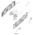
- the level adjustment mechanism (A) of which disassembled perspective views are provided in figs. 3 and 4 comprises a support frame (1) which comprises wheels (3) that allow it to move back and forth on the rails in a white good; an adjustment frame (2) which can slide up and down on the support frame (1) and which can be connected to the equipment such as rack or basket of which level adjustment is required; a rail (4) which is secured to the support frame (1) and which performs the bearing task for the up and down movement of the adjustment frame (2); a slide (5) which can move up and down inside said rail (4) and which is connected to the adjustment frame (2); a shaft (7) which is inserted into a slot on said rail (4) together with the retaining ring (8) thereon and a thumb lock (6) which is attached to the shaft (7) such that it can rotate thereon.
- the rail (4) of which front and rear perspective views are provided in fig. 5 is made of a U-shaped profile of which rear edges (41) are incurved and face each other; front face (43) comprises snap joints (42) on its both sides; said front face (43) has a shaft insertion hole (44) somewhere towards its middle part; front face (43) has also a snap joint (45) somewhere towards its lower part, and which has a channel (47) with both sides open, that is located on the one side of the shaft insertion hole (44), on the side surface (46).
- the rail (4) is secured to the support frame (1) of which detailed perspective view is provided in fig. 6. On the support frame (1), there is a channel (12) into which snap joints (42) are attached and a slot (15) into which another snap joint (45) is placed.
- Assembly of the rail (4) and support frame (1) is performed through pushing and attaching these said snap joints (42, 45) to the channel (12) and the slot (15).
- the joints (42, 45) remain secured at the position they are attached.
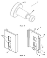
- the thumb lock (6) of which detailed perspective view is provided in fig. 7 is a part in the form of a plate, of which opposite two edges have V-shaped slots (63, 64).
- a longitudinal hole (62) through which the shaft (7) is passed and a counter bore (61) concentric with this hole (62), into which the shaft head (71) of the shaft (7) is sunk.
- a retaining ring channel (72) into which the retaining ring (8) can be placed.
- the shaft (7) is passed through the hole (62) in the center of gravity of the thumb lock (6), and the shaft head (71) is seated into the said counter bore (61); the other end of the shaft (7) is passed through the shaft insertion hole (44).
- a retaining ring (8) is placed into the retaining ring channel (72) on the front face (43) side of the rail.
- the slide (5) of which perspective views are provided in fig. 9 is a part in the form of a U profile and has slots (51) into which snap fittings (21) of the adjustment frame (2) are attached and which provide passage between its front face (50) and rear face (52) and a protrusion (53) which extends outwards on the lower part of the rear face (52).
- the upper projection (55) and the lower projection (56) which are located on the uppermost and lowermost parts of this surface (54) respectively are separated from each other.
- the lowermost position of the adjustment frame (2) relative to the support frame (1) is detected.
- the uppermost position of the adjustment frame (2) relative to the support frame (1) is the position in which the slide (5) is attached to the thumb lock (6).
- the adjustment frame (2) secured with slide (5) to each other has an ability to move up and down compared to the support frame (1) secured with the rail (4) to each other.
- the slide (5) is recessed in the rail (4) and the side profiles (23, 23') of the adjustment frame (2) in the side channels (13, 13') inside the support frame (1) such that they can only move up and down.
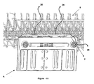
- Figs. 11 and 12 provide the perspective views of the use of the invention of level adjustment mechanism (A) in a dishwasher.
- the adjustment frame (2) in the level adjustment mechanism (A) is located in the lowermost position. This position is also the lowermost position of the basket (9) which is attached to the holders (25) on the adjustment frame (2).
- Fig. 12 is the upper position views of the adjustment frame (2) and thus the basket (9).
- Figs. 13-19 provide the drawings concerning the operating method of the level adjustment mechanism (A) regarding its positions shown in figs. 11 and 12.
- the adjustment frame (2) is secured with the slide (5) to each other and the support frame (1) is secured with the rail (4) to each other.
- the movement of the slide (5) relative to rail (4) summarizes the operation mode of the inventive mechanism (A). Therefore, figs. 13-19 explain the movement of the slide (5) in the level adjustment mechanism (A) relative to the rail (4) and the thumb lock (6) and as a result of this movement, the lower and upper positions of the slide (5).
- the lower and upper positions of the slide (5) detect the lower and upper positions of the adjustment frame (2) and the parts such as rack or basket attached thereto.
- Fig. 13 provides the views of the slide (5), rail (4) and thumb lock (6) from one direction. In this case, the slide (5) is in the lowermost position.
- Figs. 14-19 provide the detailed positions of this mechanism shown in fig. 13 during operation.
- Fig. 14 provides the lowermost position of the slide (5); in this position, the upper projection (55), the lower, projection (56) and the protrusion (53) on the slide (5) are in the baseline position.
- Fig. 15 provides the position of the slide (5) shifted upwards. In this position, the protrusion (53) contacts the V-shaped slot (63) which is located in the lower side of the thumb lock (6) and rotates the thumb lock (6) somewhat counter-clockwise.
- Fig. 16 shows the next stage; in this stage, the slide (5) is lowered somewhat and the upper projection (55) is placed into the V shaped-slot (64) on the upper part of the thumb lock (6), thus the thumb lock (6) is allowed to rotate somewhat more counter-clockwise. The position shown in fig.
- FIG. 16 is the position in which the slide (5) is attached to the thumb lock (6) and suspended, and the slide (5) and the thumb lock (6) are jammed. In this position, the slide (5), the adjustment frame (2) attached thereto and thus the parts such as rack, basket, etc. remain in the uppermost position.
- the upper projection (55) has an ability to jam in the V shaped-slot (64) such that it cannot move downwards any more.
- Fig. 17 shows the position in which the slide (5) disengages from the thumb lock (6). In order to allow this, the slide (5) is raised somewhat and the upper projection (55) disengages from the V shaped-slot (64).
- the protrusion (53) contacts the lower right surface of the lock (6) relative to the rotation axis and rotates the lock (6) again counter-clockwise; the left part of the lock (6) relative to the rotation axis also enters into the space between the upper and lower projections (55, 56).
- the lower projection (56) and the protrusion (53) come into a position in which they contact the lower surface of the lock (6).
- the slide (5) is lowered downwards and the upper projection (55) contacts the top left surface of the lock (6) relative to the rotation axis and rotates the lock (6) again counter-clockwise. This position is shown in fig. 18.
Landscapes
- Washing And Drying Of Tableware (AREA)
- Drawers Of Furniture (AREA)
Abstract
Description
- This invention relates to a level adjustment mechanism used to adjust the vertical position of the parts in white goods such as rack, basket, etc. which are located therein.
- The height of the basket can be adjusted by the user depending on the sizes and heights of the goods which are to be placed into the lower and upper baskets located in white goods. The heights of the baskets located in white goods can be adjusted through various mechanisms. In general, these mechanisms enable the basket to be secured in two different positions.
- In a system described in the published patent document
WO 02/087408 - In the
published patent document US5595200 , there is a mechanism which is attached to the side of the upper basket. The part to which the wheels allowing the movement of the basket on a rail are connected is assembled to this mechanism with a sliding joint. During up and down movement of the basket, the pin which is located inside the part on the rail moves within a slot with special geometry, which is located inside the part on the basket. The pin which comes to the fixing point of the slot is inserted here, thus allowing the system to be secured. By raising the basket to some extent, it is ensured that the slot disengages from the pin, and the basket comes to a lower position. - The level adjustment mechanism of the invention has been developed unlike the prior art mentioned above. In this invention, in order to raise a rack or a basket in a white good to an upper position, these parts are pulled up and remain in this position by attaching a thumb lock mechanism when they reach an upper position. If it is required to be brought down to a lower position, it is sufficient to pull it up somewhat more and then bring it down.
- An aim of this invention is to ensure that the heights of the racks or baskets in a white good are adjusted such that they can remain at two different positions.
- Another aim of this invention is to ensure that when the rack or basket is pulled up to an upper position, they jam in a lock mechanism under their own weights and remain in this position.
- Yet another aim of the invention is to ensure that the basket or rack is brought down to a lower position by raising it somewhat and then re-lowering it.
- The basket level adjustment mechanism of the invention is shown in the attached drawings, wherein:
- Fig. 1 is an assembled perspective view of the inventive level adjustment mechanism.
- Fig. 2 is another assembled perspective view of the level adjustment mechanism.
- Fig. 3 is a pre-assembly perspective view of the level adjustment mechanism from one direction.
- Fig. 4 is a pre-assembly perspective view of the level adjustment mechanism from another direction.
- Fig. 5 is the front and rear perspective views of the rail.
- Fig. 6 is a perspective view of the support frame.
- Fig. 7 is a perspective view of the thumb lock.
- Fig. 8 is a perspective view of the shaft.
- Fig. 9 is a perspective view of the slide.
- Fig. 10 is a perspective view of the adjustment frame.
- Fig. 11 is a perspective view of the use of the level adjustment mechanism in a dishwasher.
- Fig. 12 is another perspective view of the use of the level adjustment mechanism in a dishwasher.
- Fig. 13 is the views of the slide, rail, and thumb lock from one direction.
- Figs. 14-19 are the detailed positions of the inventive mechanism during operation.
- The parts in the figures are numbered one by one and the corresponding terms of these numbers are given below.
Level adjustment mechanism (A)
Support frame (1)
Adjustment frame (2)
Wheels (3)
Rail (4)
Slide (5)
Thumb lock (6)
Shaft (7)
Retaining ring (8)
Basket (9)
Rear surface (10)
Channel (12)
Channels (13, 13')
Set (14, 14')
Slot (15)
Front surface (20)
Snap fitting (21)
Protrusion (22, 22')
Side profiles (23, 23')
Holders (25)
Rear edges (41)
Snap joints (42)
Front face (43)
Shaft insertion hole (44)
Snap joint (45)
Side surface (46)
Channel (47)
Front face (50)
Slots (51)
Rear face (52)
Protrusion (53)
Side surface (54)
Upper projection (55)
Lower projection (56)
Opening (57)
Counter bore (61)
Hole (62)
V shaped-slot (63)
V shaped-slot (64)
Shaft head (71)
Retaining ring channel (72) - Figs. 1 and 2 provide the assembled perspective views of the inventive level adjustment mechanism (A). The level adjustment mechanism (A) of which disassembled perspective views are provided in figs. 3 and 4 comprises a support frame (1) which comprises wheels (3) that allow it to move back and forth on the rails in a white good; an adjustment frame (2) which can slide up and down on the support frame (1) and which can be connected to the equipment such as rack or basket of which level adjustment is required; a rail (4) which is secured to the support frame (1) and which performs the bearing task for the up and down movement of the adjustment frame (2); a slide (5) which can move up and down inside said rail (4) and which is connected to the adjustment frame (2); a shaft (7) which is inserted into a slot on said rail (4) together with the retaining ring (8) thereon and a thumb lock (6) which is attached to the shaft (7) such that it can rotate thereon.
- The rail (4) of which front and rear perspective views are provided in fig. 5 is made of a U-shaped profile of which rear edges (41) are incurved and face each other; front face (43) comprises snap joints (42) on its both sides; said front face (43) has a shaft insertion hole (44) somewhere towards its middle part; front face (43) has also a snap joint (45) somewhere towards its lower part, and which has a channel (47) with both sides open, that is located on the one side of the shaft insertion hole (44), on the side surface (46). The rail (4) is secured to the support frame (1) of which detailed perspective view is provided in fig. 6. On the support frame (1), there is a channel (12) into which snap joints (42) are attached and a slot (15) into which another snap joint (45) is placed. Assembly of the rail (4) and support frame (1) is performed through pushing and attaching these said snap joints (42, 45) to the channel (12) and the slot (15). By the protrusions on the snap joints (42, 45), the joints (42, 45) remain secured at the position they are attached.
- The thumb lock (6) of which detailed perspective view is provided in fig. 7 is a part in the form of a plate, of which opposite two edges have V-shaped slots (63, 64). In the center of gravity of the thumb lock (6), there is a longitudinal hole (62) through which the shaft (7) is passed and a counter bore (61) concentric with this hole (62), into which the shaft head (71) of the shaft (7) is sunk. On the one end of the shaft (7) of which details are shown in fig. 8, there is a retaining ring channel (72) into which the retaining ring (8) can be placed. In the assembled position of the thumb lock (6) on the rail (4), the shaft (7) is passed through the hole (62) in the center of gravity of the thumb lock (6), and the shaft head (71) is seated into the said counter bore (61); the other end of the shaft (7) is passed through the shaft insertion hole (44). In order to prevent the dislocation of the shaft (7) from the shaft insertion hole (44) and said hole (62) in this position, a retaining ring (8) is placed into the retaining ring channel (72) on the front face (43) side of the rail.
- The slide (5) of which perspective views are provided in fig. 9 is a part in the form of a U profile and has slots (51) into which snap fittings (21) of the adjustment frame (2) are attached and which provide passage between its front face (50) and rear face (52) and a protrusion (53) which extends outwards on the lower part of the rear face (52). In addition, through the opening (57) on the side surface (54) of the slide (5), the upper projection (55) and the lower projection (56) which are located on the uppermost and lowermost parts of this surface (54) respectively are separated from each other.
- On the adjustment frame (2) of which perspective views are provided in fig. 10, there are snap fittings (21) attached into the slots (51) on the slide (5). There are also side profiles (23, 23') on the both sides of this frame (2) such that they enter into the channels (13, 13') which extend from up to down at the sides of the support frame (1). The protrusions (22, 22') which are located on the front surface (20) of the adjustment frame (2) are also positioned such that they are seated on the top surface of the set (14, 14') of which lower surfaces are located on the rear surface (10) of the support frame (1). With the help of the relationship of the protrusions (22, 22') with the set (14, 14'), the lowermost position of the adjustment frame (2) relative to the support frame (1) is detected. The uppermost position of the adjustment frame (2) relative to the support frame (1) is the position in which the slide (5) is attached to the thumb lock (6). There are also holders (25) in the upper part of the adjustment frame (2), to which the parts such as rack or basket can be attached.
- In the invention of level adjustment mechanism (A) of which assembled position is shown in figs. 1 and 2, the adjustment frame (2) secured with slide (5) to each other has an ability to move up and down compared to the support frame (1) secured with the rail (4) to each other. In order to allow this movement, the slide (5) is recessed in the rail (4) and the side profiles (23, 23') of the adjustment frame (2) in the side channels (13, 13') inside the support frame (1) such that they can only move up and down.
- Figs. 11 and 12 provide the perspective views of the use of the invention of level adjustment mechanism (A) in a dishwasher. In the exemplary demonstration provided in fig. 11, the adjustment frame (2) in the level adjustment mechanism (A) is located in the lowermost position. This position is also the lowermost position of the basket (9) which is attached to the holders (25) on the adjustment frame (2). Fig. 12 is the upper position views of the adjustment frame (2) and thus the basket (9). Figs. 13-19 provide the drawings concerning the operating method of the level adjustment mechanism (A) regarding its positions shown in figs. 11 and 12.
- As mentioned above, in the level adjustment mechanism (A), the adjustment frame (2) is secured with the slide (5) to each other and the support frame (1) is secured with the rail (4) to each other. In brief, the movement of the slide (5) relative to rail (4) summarizes the operation mode of the inventive mechanism (A). Therefore, figs. 13-19 explain the movement of the slide (5) in the level adjustment mechanism (A) relative to the rail (4) and the thumb lock (6) and as a result of this movement, the lower and upper positions of the slide (5). The lower and upper positions of the slide (5) detect the lower and upper positions of the adjustment frame (2) and the parts such as rack or basket attached thereto.
- Fig. 13 provides the views of the slide (5), rail (4) and thumb lock (6) from one direction. In this case, the slide (5) is in the lowermost position. Figs. 14-19 provide the detailed positions of this mechanism shown in fig. 13 during operation.
- Fig. 14 provides the lowermost position of the slide (5); in this position, the upper projection (55), the lower, projection (56) and the protrusion (53) on the slide (5) are in the baseline position. Fig. 15 provides the position of the slide (5) shifted upwards. In this position, the protrusion (53) contacts the V-shaped slot (63) which is located in the lower side of the thumb lock (6) and rotates the thumb lock (6) somewhat counter-clockwise. Fig. 16 shows the next stage; in this stage, the slide (5) is lowered somewhat and the upper projection (55) is placed into the V shaped-slot (64) on the upper part of the thumb lock (6), thus the thumb lock (6) is allowed to rotate somewhat more counter-clockwise. The position shown in fig. 16 is the position in which the slide (5) is attached to the thumb lock (6) and suspended, and the slide (5) and the thumb lock (6) are jammed. In this position, the slide (5), the adjustment frame (2) attached thereto and thus the parts such as rack, basket, etc. remain in the uppermost position. In order to allow the attachment and suspension of the slide (5) into the thumb lock (6), the upper projection (55) has an ability to jam in the V shaped-slot (64) such that it cannot move downwards any more. Fig. 17 shows the position in which the slide (5) disengages from the thumb lock (6). In order to allow this, the slide (5) is raised somewhat and the upper projection (55) disengages from the V shaped-slot (64). On the continuation of the movement, the protrusion (53) contacts the lower right surface of the lock (6) relative to the rotation axis and rotates the lock (6) again counter-clockwise; the left part of the lock (6) relative to the rotation axis also enters into the space between the upper and lower projections (55, 56). As shown in fig. 17; in this stage, the lower projection (56) and the protrusion (53) come into a position in which they contact the lower surface of the lock (6). Thereafter, the slide (5) is lowered downwards and the upper projection (55) contacts the top left surface of the lock (6) relative to the rotation axis and rotates the lock (6) again counter-clockwise. This position is shown in fig. 18. On the continuation of the movement, the lock (6) and the slide (5) are completely separated from each other as shown in fig. 19, the slide (5) returns its lowermost position which is its baseline position and the lock (6) turns and takes its initial position. In order to attach the slide (5) to the lock (6) and shift it to an upper position, the stages shown from fig. 14 onwards are repeated.
- The above preferred level adjustment mechanism (A) are not intended to limit the protection scope of the invention. According to the information described with the invention, modifications to be performed on this preferred level adjustment mechanism (A) should be evaluated within the protection scope of the invention.
Claims (12)
- A level adjustment mechanism (A), which is used for the level adjustment of an equipment such as rack or basket located in white goods, comprising a support frame (1) which is located in a fixed position, a rail (4) which is connected to the support frame (1), a slide (5) which is recessed such that it can move up and down within the rail (4), an adjustment frame (2) which is connected to the slide (5) and onto which said racks or baskets can be attached, a thumb lock (6) in the form of a plate which allows the suspension of the slide (5) when it comes to an upper position and which is connected to the rail (4) such that it can rotate freely around its center of gravity and which has V-shaped slots (63, 64) on its two opposite edges, characterized in that
for allowing the slide (5) to contact the V-shaped slot (63) which is located in the lower part of the thumb lock (6) and rotate the lock (6) somewhat counter-clockwise when it comes to the shifted upwards position from its lowermost position, there is a protrusion (53) on the lower part of the rear face (52) of the slide (5), which extends outwards;
there is an upper projection (55) on the upper part of the side surface (54) of the slide (5), which is placed into the V shaped-slot (64) on the upper part of the thumb lock (6) and turns the lock (6) somewhat more counter-clockwise after the slide (5) is lowered somewhat;
in order to allow the attachment and suspension of the slide (5) into the thumb lock (6), the upper projection (55) has an ability to jam in the V shaped-slot (64) such that it cannot move downwards any more;
the slide (5) is raised somewhat and thus the upper projection (55) disengages from the V shaped-slot (64); on the continuation of the movement, in order to rotate the lock (6) again counter-clockwise after the protrusion (53) contacts the lower right surface of the lock (6) relative to the rotation axis; there is a opening (57) between the upper and lower projections (55, 56) such that the left part of the lock (6) relative to the rotation axis can enter thereinto;
in order to allow the slide (5) to return to its lowermost position which is its baseline position, after the lower projection (56) and the protrusion (53) are brought to a position such that they contact the lower surface of the lock (6), the slide (5) is lowered downwards, thus the upper projection (55) contacts the top left surface of the lock (6) relative to the rotation axis and rotates the lock (6) again counter-clockwise, and the lock (6) and the slide (5) have the ability to be completely separated from each other. - A level adjustment mechanism (A) according to the claim 1, wherein the slide (5) is recessed in the rail (4) and the side profiles (23, 23') of the adjustment frame (2) in the side channels (13, 13') inside the support frame (1) such that they can only move up and down.
- A level adjustment mechanism (A) according to the claim 1, wherein there is a shaft insertion hole (44) on the front face (43) of the rail (4) into which the shaft (7) together with the thumb lock (6) thereon is inserted, and a channel (47) with both sides open, that is located on the one side of the shaft insertion hole (44), on the side surface (46) such that it will allow the thumb lock (6) to freely rotate.
- A level adjustment mechanism (A) according to the claim 1, wherein the said slide (5) is a part in the form of a U profile and has slots (51) thereon into which snap fittings (21) of the adjustment frame (2) are attached and which provide passage between its front face (50) and rear face (52).
- A level adjustment mechanism (A) according to the claim 1, wherein in the center of gravity of the thumb lock (6), there is a longitudinal hole (62) through which the shaft (7) is passed and a counter bore (61) concentric with this hole (62), into which the shaft head (71) of the shaft (7) is sunk.
- A level adjustment mechanism (A) according to the claim 1, wherein in the assembled position of the thumb lock (6) on the rail (4), the shaft (7) is passed through the hole (62) in the center of gravity of the thumb lock (6), and the shaft head (71) is seated into the said counter bore (61); the other end of the shaft (7) is passed through the shaft insertion hole (44); in order to prevent the dislocation of the shaft (7) from the shaft insertion hole (44) and said hole (62) in this position, a retaining ring (8) is placed into the retaining ring channel (72) on the shaft (7) on the front face (43) side of the rail.
- A level adjustment mechanism (A) according to the claim 1, wherein the said rail (4) is in the structure of a U-shaped profile of which rear edges (41) are incurved and face each other; front face (43) contains snap joints (42, 45).
- A level adjustment mechanism (A) according to the claim 1, wherein on the support frame (1), there is a channel (12) into which snap joints (42) are attached and also a slot (15) into which another snap joint (45) is placed.
- A level adjustment mechanism (A) according to the claim 1, wherein on the adjustment frame (2), there are snap fittings (21) attached into the slots (51) on the slide (5).
- A level adjustment mechanism (A) according to the claim 1, wherein in order to detect the lowermost position of the adjustment frame (2) relative to the support frame (1), the protrusions (22, 22') which are located on the front surface (20) of the adjustment frame (2) are positioned such that they are seated on the top surface of the set (14, 14') of which lower surfaces are located on the rear surface (10) of the support frame (1).
- A level adjustment mechanism (A) according to the claim 1, wherein there are holders (25) in the upper part of the adjustment frame (2), to which the parts such as rack or basket can be attached.
- A level adjustment mechanism (A) according to the claim 1, wherein in order to allow the back and forth movement of the support frame (1) on the rails (4) in a white good, there are wheels (3) on the support frame (1).
Priority Applications (3)
| Application Number | Priority Date | Filing Date | Title |
|---|---|---|---|
| AT06113618T ATE424136T1 (en) | 2006-05-08 | 2006-05-08 | DEVICE FOR ADJUSTING THE HEIGHT OF A DISHWASHER IN A HOUSEHOLD DISHWASHER |
| EP06113618A EP1854394B1 (en) | 2006-05-08 | 2006-05-08 | Dishwasher rack or basket level adjustment mechanism |
| DE602006005472T DE602006005472D1 (en) | 2006-05-08 | 2006-05-08 | Device for adjusting the height of a dish rack in a household dishwasher |
Applications Claiming Priority (1)
| Application Number | Priority Date | Filing Date | Title |
|---|---|---|---|
| EP06113618A EP1854394B1 (en) | 2006-05-08 | 2006-05-08 | Dishwasher rack or basket level adjustment mechanism |
Publications (2)
| Publication Number | Publication Date |
|---|---|
| EP1854394A1 true EP1854394A1 (en) | 2007-11-14 |
| EP1854394B1 EP1854394B1 (en) | 2009-03-04 |
Family
ID=37072948
Family Applications (1)
| Application Number | Title | Priority Date | Filing Date |
|---|---|---|---|
| EP06113618A Expired - Lifetime EP1854394B1 (en) | 2006-05-08 | 2006-05-08 | Dishwasher rack or basket level adjustment mechanism |
Country Status (3)
| Country | Link |
|---|---|
| EP (1) | EP1854394B1 (en) |
| AT (1) | ATE424136T1 (en) |
| DE (1) | DE602006005472D1 (en) |
Cited By (4)
| Publication number | Priority date | Publication date | Assignee | Title |
|---|---|---|---|---|
| US20110114138A1 (en) * | 2008-05-02 | 2011-05-19 | Arcelik Anonim Sirketi | Dishwasher with a Device for Assembling the Basket to the Extracting Rail |
| US9579009B2 (en) | 2013-02-04 | 2017-02-28 | Whirlpool Corporation | Dishwasher with vertically adjustable dish rack |
| EP3357399A1 (en) * | 2017-02-07 | 2018-08-08 | Whirlpool Corporation | Dish rack retaining clip |
| CN110613415A (en) * | 2019-09-20 | 2019-12-27 | 青岛海尔洗碗机有限公司 | Dish washer shelf and dish washer |
Citations (4)
| Publication number | Priority date | Publication date | Assignee | Title |
|---|---|---|---|---|
| EP0033483A2 (en) * | 1980-02-05 | 1981-08-12 | Bauknecht Hausgeräte GmbH | Height adjustment device for a rack in a domestic dishwasher |
| EP0901770A2 (en) * | 1997-09-12 | 1999-03-17 | Electrolux Zanussi S.p.A. | Dishwashing machine with height-adjustable rack |
| EP1161917A2 (en) * | 2000-06-05 | 2001-12-12 | CANDY S.p.A. | Dishwater with height adjustable rack |
| WO2002049495A1 (en) * | 2000-12-19 | 2002-06-27 | Arçel K A. . | Vertical adjustment mechanism |
-
2006
- 2006-05-08 AT AT06113618T patent/ATE424136T1/en not_active IP Right Cessation
- 2006-05-08 DE DE602006005472T patent/DE602006005472D1/en not_active Expired - Lifetime
- 2006-05-08 EP EP06113618A patent/EP1854394B1/en not_active Expired - Lifetime
Patent Citations (4)
| Publication number | Priority date | Publication date | Assignee | Title |
|---|---|---|---|---|
| EP0033483A2 (en) * | 1980-02-05 | 1981-08-12 | Bauknecht Hausgeräte GmbH | Height adjustment device for a rack in a domestic dishwasher |
| EP0901770A2 (en) * | 1997-09-12 | 1999-03-17 | Electrolux Zanussi S.p.A. | Dishwashing machine with height-adjustable rack |
| EP1161917A2 (en) * | 2000-06-05 | 2001-12-12 | CANDY S.p.A. | Dishwater with height adjustable rack |
| WO2002049495A1 (en) * | 2000-12-19 | 2002-06-27 | Arçel K A. . | Vertical adjustment mechanism |
Cited By (6)
| Publication number | Priority date | Publication date | Assignee | Title |
|---|---|---|---|---|
| US20110114138A1 (en) * | 2008-05-02 | 2011-05-19 | Arcelik Anonim Sirketi | Dishwasher with a Device for Assembling the Basket to the Extracting Rail |
| US9462930B2 (en) * | 2008-05-02 | 2016-10-11 | Arcelik Anonim Sirketi | Dishwasher with a device for assembling the basket to the extracting rail |
| US9579009B2 (en) | 2013-02-04 | 2017-02-28 | Whirlpool Corporation | Dishwasher with vertically adjustable dish rack |
| EP3357399A1 (en) * | 2017-02-07 | 2018-08-08 | Whirlpool Corporation | Dish rack retaining clip |
| US10136795B2 (en) | 2017-02-07 | 2018-11-27 | Whirlpool Corporation | Dish rack retaining clip |
| CN110613415A (en) * | 2019-09-20 | 2019-12-27 | 青岛海尔洗碗机有限公司 | Dish washer shelf and dish washer |
Also Published As
| Publication number | Publication date |
|---|---|
| EP1854394B1 (en) | 2009-03-04 |
| DE602006005472D1 (en) | 2009-04-16 |
| ATE424136T1 (en) | 2009-03-15 |
Similar Documents
| Publication | Publication Date | Title |
|---|---|---|
| EP2248442B1 (en) | Stabilizing assembly of drawable carrier | |
| CN103096757B (en) | Slide assembly with dual handed ball retainer latch | |
| EP2498031A1 (en) | Refrigerating appliance | |
| CN107249386B (en) | Sliding pivot mechanisms for furniture or appliance shelves, furniture and appliances | |
| JP5782051B2 (en) | Drawer system | |
| CN101588691B (en) | Slide rail interlocking device | |
| GB2533197A (en) | Frame height adjusting mechanism and frame therewith | |
| EP1417390A1 (en) | Drawer open position controller | |
| CA2619289A1 (en) | Locking shoe formed in non-rotatable halves for curl spring window balance system | |
| CN112135550B (en) | Sliding pivoting mechanism of shelf of furniture or household appliance and furniture or household appliance | |
| CN101346079B (en) | Telescopic guide for a furniture part that can be displaced in a furniture body | |
| EP1202658B1 (en) | Dropping side shelf assembly | |
| EP1854394B1 (en) | Dishwasher rack or basket level adjustment mechanism | |
| EP1245765A1 (en) | Cabinet having double locking mechanism | |
| KR20040070075A (en) | Refrigerator Compartment Housing Vertically Adjustable Shelves | |
| EP1847208B1 (en) | Lid mechanism for a drawer-type dishwasher | |
| EP2390447B1 (en) | Bracket with front coupling for carriages of sliding wings or doors | |
| EP1532402B1 (en) | Extendable oven rack assembly | |
| CN111970942B (en) | Pull-out guide | |
| JP2015014419A (en) | Door opening/closing structure of storage house | |
| US7694357B2 (en) | Safety bar for a bathtub | |
| CN106961816A (en) | Sliding rail assembly | |
| KR102904118B1 (en) | Receiving Unit Apparatus for Motor Control Center with Safety and Position Alignment | |
| EP1980703A2 (en) | Sliding guide for wardrobe doors | |
| EP1366703B1 (en) | Built-in domestic appliance with decorative panel applied to the door |
Legal Events
| Date | Code | Title | Description |
|---|---|---|---|
| PUAI | Public reference made under article 153(3) epc to a published international application that has entered the european phase |
Free format text: ORIGINAL CODE: 0009012 |
|
| AK | Designated contracting states |
Kind code of ref document: A1 Designated state(s): AT BE BG CH CY CZ DE DK EE ES FI FR GB GR HU IE IS IT LI LT LU LV MC NL PL PT RO SE SI SK TR |
|
| AX | Request for extension of the european patent |
Extension state: AL BA HR MK YU |
|
| 17P | Request for examination filed |
Effective date: 20080118 |
|
| AKX | Designation fees paid |
Designated state(s): AT BE BG CH CY CZ DE DK EE ES FI FR GB GR HU IE IS IT LI LT LU LV MC NL PL PT RO SE SI SK TR |
|
| GRAP | Despatch of communication of intention to grant a patent |
Free format text: ORIGINAL CODE: EPIDOSNIGR1 |
|
| GRAP | Despatch of communication of intention to grant a patent |
Free format text: ORIGINAL CODE: EPIDOSNIGR1 |
|
| GRAS | Grant fee paid |
Free format text: ORIGINAL CODE: EPIDOSNIGR3 |
|
| GRAA | (expected) grant |
Free format text: ORIGINAL CODE: 0009210 |
|
| AK | Designated contracting states |
Kind code of ref document: B1 Designated state(s): AT BE BG CH CY CZ DE DK EE ES FI FR GB GR HU IE IS IT LI LT LU LV MC NL PL PT RO SE SI SK TR |
|
| REG | Reference to a national code |
Ref country code: GB Ref legal event code: FG4D |
|
| REG | Reference to a national code |
Ref country code: CH Ref legal event code: EP |
|
| REG | Reference to a national code |
Ref country code: IE Ref legal event code: FG4D |
|
| REF | Corresponds to: |
Ref document number: 602006005472 Country of ref document: DE Date of ref document: 20090416 Kind code of ref document: P |
|
| PG25 | Lapsed in a contracting state [announced via postgrant information from national office to epo] |
Ref country code: LT Free format text: LAPSE BECAUSE OF FAILURE TO SUBMIT A TRANSLATION OF THE DESCRIPTION OR TO PAY THE FEE WITHIN THE PRESCRIBED TIME-LIMIT Effective date: 20090304 Ref country code: NL Free format text: LAPSE BECAUSE OF FAILURE TO SUBMIT A TRANSLATION OF THE DESCRIPTION OR TO PAY THE FEE WITHIN THE PRESCRIBED TIME-LIMIT Effective date: 20090304 Ref country code: FI Free format text: LAPSE BECAUSE OF FAILURE TO SUBMIT A TRANSLATION OF THE DESCRIPTION OR TO PAY THE FEE WITHIN THE PRESCRIBED TIME-LIMIT Effective date: 20090304 Ref country code: SI Free format text: LAPSE BECAUSE OF FAILURE TO SUBMIT A TRANSLATION OF THE DESCRIPTION OR TO PAY THE FEE WITHIN THE PRESCRIBED TIME-LIMIT Effective date: 20090304 |
|
| NLV1 | Nl: lapsed or annulled due to failure to fulfill the requirements of art. 29p and 29m of the patents act | ||
| PG25 | Lapsed in a contracting state [announced via postgrant information from national office to epo] |
Ref country code: SE Free format text: LAPSE BECAUSE OF FAILURE TO SUBMIT A TRANSLATION OF THE DESCRIPTION OR TO PAY THE FEE WITHIN THE PRESCRIBED TIME-LIMIT Effective date: 20090604 Ref country code: PL Free format text: LAPSE BECAUSE OF FAILURE TO SUBMIT A TRANSLATION OF THE DESCRIPTION OR TO PAY THE FEE WITHIN THE PRESCRIBED TIME-LIMIT Effective date: 20090304 Ref country code: AT Free format text: LAPSE BECAUSE OF FAILURE TO SUBMIT A TRANSLATION OF THE DESCRIPTION OR TO PAY THE FEE WITHIN THE PRESCRIBED TIME-LIMIT Effective date: 20090304 Ref country code: LV Free format text: LAPSE BECAUSE OF FAILURE TO SUBMIT A TRANSLATION OF THE DESCRIPTION OR TO PAY THE FEE WITHIN THE PRESCRIBED TIME-LIMIT Effective date: 20090304 |
|
| PG25 | Lapsed in a contracting state [announced via postgrant information from national office to epo] |
Ref country code: BE Free format text: LAPSE BECAUSE OF FAILURE TO SUBMIT A TRANSLATION OF THE DESCRIPTION OR TO PAY THE FEE WITHIN THE PRESCRIBED TIME-LIMIT Effective date: 20090304 |
|
| PG25 | Lapsed in a contracting state [announced via postgrant information from national office to epo] |
Ref country code: CZ Free format text: LAPSE BECAUSE OF FAILURE TO SUBMIT A TRANSLATION OF THE DESCRIPTION OR TO PAY THE FEE WITHIN THE PRESCRIBED TIME-LIMIT Effective date: 20090304 Ref country code: ES Free format text: LAPSE BECAUSE OF FAILURE TO SUBMIT A TRANSLATION OF THE DESCRIPTION OR TO PAY THE FEE WITHIN THE PRESCRIBED TIME-LIMIT Effective date: 20090615 Ref country code: PT Free format text: LAPSE BECAUSE OF FAILURE TO SUBMIT A TRANSLATION OF THE DESCRIPTION OR TO PAY THE FEE WITHIN THE PRESCRIBED TIME-LIMIT Effective date: 20090818 Ref country code: EE Free format text: LAPSE BECAUSE OF FAILURE TO SUBMIT A TRANSLATION OF THE DESCRIPTION OR TO PAY THE FEE WITHIN THE PRESCRIBED TIME-LIMIT Effective date: 20090304 |
|
| PG25 | Lapsed in a contracting state [announced via postgrant information from national office to epo] |
Ref country code: IS Free format text: LAPSE BECAUSE OF FAILURE TO SUBMIT A TRANSLATION OF THE DESCRIPTION OR TO PAY THE FEE WITHIN THE PRESCRIBED TIME-LIMIT Effective date: 20090704 Ref country code: SK Free format text: LAPSE BECAUSE OF FAILURE TO SUBMIT A TRANSLATION OF THE DESCRIPTION OR TO PAY THE FEE WITHIN THE PRESCRIBED TIME-LIMIT Effective date: 20090304 Ref country code: RO Free format text: LAPSE BECAUSE OF FAILURE TO SUBMIT A TRANSLATION OF THE DESCRIPTION OR TO PAY THE FEE WITHIN THE PRESCRIBED TIME-LIMIT Effective date: 20090304 |
|
| PG25 | Lapsed in a contracting state [announced via postgrant information from national office to epo] |
Ref country code: MC Free format text: LAPSE BECAUSE OF NON-PAYMENT OF DUE FEES Effective date: 20090531 |
|
| PLBE | No opposition filed within time limit |
Free format text: ORIGINAL CODE: 0009261 |
|
| STAA | Information on the status of an ep patent application or granted ep patent |
Free format text: STATUS: NO OPPOSITION FILED WITHIN TIME LIMIT |
|
| PG25 | Lapsed in a contracting state [announced via postgrant information from national office to epo] |
Ref country code: BG Free format text: LAPSE BECAUSE OF FAILURE TO SUBMIT A TRANSLATION OF THE DESCRIPTION OR TO PAY THE FEE WITHIN THE PRESCRIBED TIME-LIMIT Effective date: 20090604 Ref country code: DK Free format text: LAPSE BECAUSE OF FAILURE TO SUBMIT A TRANSLATION OF THE DESCRIPTION OR TO PAY THE FEE WITHIN THE PRESCRIBED TIME-LIMIT Effective date: 20090304 |
|
| 26N | No opposition filed |
Effective date: 20091207 |
|
| PG25 | Lapsed in a contracting state [announced via postgrant information from national office to epo] |
Ref country code: IE Free format text: LAPSE BECAUSE OF NON-PAYMENT OF DUE FEES Effective date: 20090508 |
|
| PG25 | Lapsed in a contracting state [announced via postgrant information from national office to epo] |
Ref country code: GR Free format text: LAPSE BECAUSE OF FAILURE TO SUBMIT A TRANSLATION OF THE DESCRIPTION OR TO PAY THE FEE WITHIN THE PRESCRIBED TIME-LIMIT Effective date: 20090605 |
|
| REG | Reference to a national code |
Ref country code: CH Ref legal event code: PL |
|
| PG25 | Lapsed in a contracting state [announced via postgrant information from national office to epo] |
Ref country code: LI Free format text: LAPSE BECAUSE OF NON-PAYMENT OF DUE FEES Effective date: 20100531 Ref country code: CH Free format text: LAPSE BECAUSE OF NON-PAYMENT OF DUE FEES Effective date: 20100531 |
|
| PG25 | Lapsed in a contracting state [announced via postgrant information from national office to epo] |
Ref country code: LU Free format text: LAPSE BECAUSE OF NON-PAYMENT OF DUE FEES Effective date: 20090508 |
|
| PG25 | Lapsed in a contracting state [announced via postgrant information from national office to epo] |
Ref country code: HU Free format text: LAPSE BECAUSE OF FAILURE TO SUBMIT A TRANSLATION OF THE DESCRIPTION OR TO PAY THE FEE WITHIN THE PRESCRIBED TIME-LIMIT Effective date: 20090905 |
|
| PG25 | Lapsed in a contracting state [announced via postgrant information from national office to epo] |
Ref country code: CY Free format text: LAPSE BECAUSE OF FAILURE TO SUBMIT A TRANSLATION OF THE DESCRIPTION OR TO PAY THE FEE WITHIN THE PRESCRIBED TIME-LIMIT Effective date: 20090304 |
|
| PGFP | Annual fee paid to national office [announced via postgrant information from national office to epo] |
Ref country code: IT Payment date: 20120523 Year of fee payment: 7 |
|
| PG25 | Lapsed in a contracting state [announced via postgrant information from national office to epo] |
Ref country code: IT Free format text: LAPSE BECAUSE OF NON-PAYMENT OF DUE FEES Effective date: 20130508 |
|
| REG | Reference to a national code |
Ref country code: FR Ref legal event code: PLFP Year of fee payment: 10 |
|
| REG | Reference to a national code |
Ref country code: FR Ref legal event code: PLFP Year of fee payment: 11 |
|
| REG | Reference to a national code |
Ref country code: DE Ref legal event code: R082 Ref document number: 602006005472 Country of ref document: DE Representative=s name: LEONHARD & PARTNER PATENTANWAELTE, DE |
|
| REG | Reference to a national code |
Ref country code: DE Ref legal event code: R084 Ref document number: 602006005472 Country of ref document: DE |
|
| REG | Reference to a national code |
Ref country code: FR Ref legal event code: PLFP Year of fee payment: 12 |
|
| REG | Reference to a national code |
Ref country code: GB Ref legal event code: 746 Effective date: 20170419 |
|
| REG | Reference to a national code |
Ref country code: FR Ref legal event code: PLFP Year of fee payment: 13 |
|
| REG | Reference to a national code |
Ref country code: DE Ref legal event code: R082 Ref document number: 602006005472 Country of ref document: DE Representative=s name: LEONHARD, REIMUND, DIPL.-ING., DE |
|
| PGFP | Annual fee paid to national office [announced via postgrant information from national office to epo] |
Ref country code: DE Payment date: 20250521 Year of fee payment: 20 |
|
| PGFP | Annual fee paid to national office [announced via postgrant information from national office to epo] |
Ref country code: GB Payment date: 20250527 Year of fee payment: 20 |
|
| PGFP | Annual fee paid to national office [announced via postgrant information from national office to epo] |
Ref country code: FR Payment date: 20250528 Year of fee payment: 20 |
|
| PGFP | Annual fee paid to national office [announced via postgrant information from national office to epo] |
Ref country code: TR Payment date: 20250505 Year of fee payment: 20 |