EP1854387A2 - Automatic brewed beverage dispenser - Google Patents
Automatic brewed beverage dispenser Download PDFInfo
- Publication number
- EP1854387A2 EP1854387A2 EP07356062A EP07356062A EP1854387A2 EP 1854387 A2 EP1854387 A2 EP 1854387A2 EP 07356062 A EP07356062 A EP 07356062A EP 07356062 A EP07356062 A EP 07356062A EP 1854387 A2 EP1854387 A2 EP 1854387A2
- Authority
- EP
- European Patent Office
- Prior art keywords
- chute
- dispenser according
- wiper arm
- cam
- powdery product
- Prior art date
- Legal status (The legal status is an assumption and is not a legal conclusion. Google has not performed a legal analysis and makes no representation as to the accuracy of the status listed.)
- Granted
Links
Images


Classifications
-
- A—HUMAN NECESSITIES
- A47—FURNITURE; DOMESTIC ARTICLES OR APPLIANCES; COFFEE MILLS; SPICE MILLS; SUCTION CLEANERS IN GENERAL
- A47J—KITCHEN EQUIPMENT; COFFEE MILLS; SPICE MILLS; APPARATUS FOR MAKING BEVERAGES
- A47J31/00—Apparatus for making beverages
- A47J31/44—Parts or details or accessories of beverage-making apparatus
- A47J31/60—Cleaning devices
-
- A—HUMAN NECESSITIES
- A47—FURNITURE; DOMESTIC ARTICLES OR APPLIANCES; COFFEE MILLS; SPICE MILLS; SUCTION CLEANERS IN GENERAL
- A47J—KITCHEN EQUIPMENT; COFFEE MILLS; SPICE MILLS; APPARATUS FOR MAKING BEVERAGES
- A47J31/00—Apparatus for making beverages
- A47J31/40—Beverage-making apparatus with dispensing means for adding a measured quantity of ingredients, e.g. coffee, water, sugar, cocoa, milk, tea
- A47J31/404—Powder dosing devices
Definitions
- the present invention relates to an apparatus of the automatic vending machine type of beverage infused from a powdered infusion or percolation food dispenser device, such as ground coffee, tea, chocolate, etc.
- a device for preparing and dispensing hot drinks generally comprises a cold water tank, an electric pump, a boiler and an infusion head adapted to receive the powdery product in order to inject hot water from the boiler. the resulting drink is then directed to a collecting vessel. At the end of the infusion cycle, the infusion head must be opened in order to be able to introduce a new dose of infusion product after evacuating the rest of previously infused product.
- the apparatus comprises an infusion unit comprising a vertical axis infusion chamber adapted to receive a sliding pressure piston along said vertical axis actuated by the piston of a hydraulic cylinder.
- the piston of the hydraulic cylinder is connected to the pressure piston and can move from a rest position to a working position in which the pressure piston is in compression in the brewing chamber under the effect of the liquid under pressure. The transition to the rest position is by a return spring.
- This apparatus also comprises an automatic milling machine comprising a reservoir containing the mill, provided with a dispensing orifice, a chute leading the grinding to the brewing chamber, and a hub connected to a shaft which rotates. the hub blades for pushing a certain amount of ground in said chute via the dispensing orifice during driving of said shaft.
- an automatic milling machine comprising a reservoir containing the mill, provided with a dispensing orifice, a chute leading the grinding to the brewing chamber, and a hub connected to a shaft which rotates. the hub blades for pushing a certain amount of ground in said chute via the dispensing orifice during driving of said shaft.
- the document EP 1 654 968 discloses an automatic coffee machine having a device for automatically cleaning the chute of a coffee grinder dispenser.
- This machine comprises an infusion group comprising a brewing chamber fixedly mounted above a heat block for supplying hot water to the chamber.
- the infusion chamber receives a pressure piston sliding vertically inside the chamber to compact the grinding. Actuation of the pressure piston is done by a hydraulic cylinder.
- the machine also comprises a coffee grinder dispenser provided with a ground coffee transfer chute to the infusion chamber, which chute is cleaned by a cleaning device secured to the pressing piston.
- This cleaning device comprises for this purpose a rigid scraper cooperating with a pivoting chute, or even a flexible blade coming into contact with the inner wall of the chute, the scraper or the blade being driven in motion by the pressure piston.
- the movement of the scraper or the blade is however limited to that of the piston, which is performed once per brew cycle in the direction of the length of the chute.
- the particles of coffee powder scraped after closing the chamber by the piston accumulate on the piston or around the brewing chamber, which requires a systematic cleaning of the interior of the machine.
- the object of the present invention is to overcome the aforementioned drawbacks and to propose a vending machine of infused beverages comprising a powdery product dispenser able to automatically and effectively prevent the stuffing of the product to be infused into the chute leading to it. brewing chamber.
- Another object of the invention is a vending machine of infused beverages capable of preparing a quality drink with a fresh taste, while being safe and reliable in operation.
- Another object of the invention is a vending machine of infused beverages comprising an automatic cleaning device of the coffee chute which simultaneously acts to the passage of coffee in the chute.
- Another object of the invention is a vending machine for infused beverages comprising a device for automatically cleaning the coffee chute which can be economically produced while being dissociated from the brewing unit.
- the powdery product dispenser may be of the type comprising a reservoir which contains the product to be infused and inside which there is a hub with blades able to pass a certain amount of product, through a dispensing orifice, in a chute which conveys it close to the chamber of infusion.
- a dispenser may also be a coffee bean crusher which directly sends, through a dispensing orifice, or through a buffer chamber, a certain quantity of coffee into a chute which transfers it into the chamber infusion.
- a chute is a tubular conduit, open or closed, which is arranged generally vertical or inclined relative to the brewing chamber, so that the powdery product falls by gravity inside the brewing chamber.
- the chute of the dispenser is cleaned automatically by a wiper arm of an automatic cleaning device set in motion by electromechanical means.
- Electromechanical means include electric drive means, such as a motor or an electromagnet, a mechanism coupled to the wiper arm. Such a mechanism then comprises an arrangement of elements capable of transforming the mechanical energy received, at the input, of the motor shaft or of a frame of the electromagnet into a movement of the wiper arm inside. chute, out.
- This solution has the advantage of operating automatically and independently of the other components of the device, by performing a simple power supply control electromechanical means actuating the wiper arm.
- This command can be carried out manually by the user before or after having ordered an infusion cycle or it can be preprogrammed in the logic circuit of the distributor, circuit belonging to an electronic card for managing the operation of the apparatus.
- the operating parameters of the movement of the wiper arm can easily be adjusted or chosen by the user, for example depending on the quantity of product dispensed, the fineness of the grind, etc.
- said mechanism comprises an electric motor and a drive device adapted to transform the rotary movement of the output shaft of the motor into a reciprocating movement of the wiper arm.
- a paddle wheel rotated by a motor each blade then constituting a wiper arm brought successively during the rotation of the wheel in contact with the bottom wall of the chute.
- a drive device for example of the crank-rod type, is used which makes it possible to transform the rotary movement of the axis of the motor into a rectilinear reciprocating movement of the wiper arm because it is possible to obtain, with a simplified structure device, a wider sweeping movement of the walls of the chute.
- said electric motor belongs to the powdery product dispensing device.
- the fact of using the same motor to drive both the powdery product dispenser and the chute cleaning device is a very economical and space-saving solution to build a compact beverage dispenser and structure simplified.
- this makes it possible to avoid jams in the chute during the passage of the product dispensed to the infusion chamber and, at the same time, time, keep the chute always clean, while using a simple, reliable and inexpensive solution.
- the driving device comprises a cam rotated by the electric motor via a gear train.
- a rotary cam whose contour makes it possible to transform the rotational movement of the motor into an oscillating movement of the wiper arm, the gear train thus making it possible to reduce the speed of rotation, while ensuring a good pair of transmission of forces to the cam and thus to the wiper arm.
- the geared motor also serves, as the electric motor, driving the powdery product dispensing device, for example for rotating grinding wheels of a grinder or the blades of a milling doser.
- the cam drives the wiper arm in a reciprocating movement in contact with at least one wall of the chute.
- the wiper arm is thus made to perform an oscillating movement in contact with the wall of the chute, thus acting on this wall as a wiper to remove the particles of powdery product having a tendency to adhere to the chute.
- the wiper arm performs at least one round trip, preferably three round trips, during the powdery product dispensing period.
- the cam rotates about a vertical axis.
- the cam actuates a control switch of the device powdery product dispenser.
- the profile of the cam can thus actuate a control switch for starting and / or stopping grinding wheels of a coffee bean grinder or the dosing blades of a ground coffee tank after a certain number of rotations of the cam or a fraction of a turn of the latter.
- said dispensing device comprises a ground coffee tank equipped with blades, and the cam comprises means for rotating the blades of the metering device.
- the dispensing device comprises a coffee bean grinder, the cam comprising means for driving in rotation one of the grinding wheels of the grinder.
- the wiper arm is fixed to a cursor guided in translation in a plane perpendicular to the axis of rotation of the cam.
- the wiper arm is pivotally mounted about a hinge located in the vicinity of the chute, one end of the wiper arm then coming into contact with the rotary cam, thereby imparting the pivoting movement. inside the chute.
- said slider is mounted in a housing by means of a return spring, the force of the spring being opposite to that printed with the slider by the cam.
- the chute is inclined relative to the plane of the slider and the wiper arm follows the inclination of the chute.
- An inclined chute forms a springboard for pouring ground coffee, directing the coffee towards the brewing chamber; for an effective action, the wiper arm then has the same inclination as the chute and more particularly with the wall of the latter on which the wiper arm is likely to come into contact.
- the wiper arm translates in the direction of the width of the chute.
- the wiper arm is disposed near the dispensing orifice and the amplitude of the movement effected by the wiper arm is substantially equal to the width of the dispensing orifice.
- said wiper arm is made of a stainless steel wire.
- Such a wire in particular with a diameter of less than 3 mm, can advantageously be used to clean the ground coffee particles because the latter do not adhere to the wire.
- a Teflon ® type coating on a steel wire or the coating of a plastic material elastomer then ensuring better cleaning of the walls of the chute.
- said wiper arm bears resiliently against the wall of the chute.
- This resilient support could be done by the elasticity of the wiper arm itself and / or the spring mount in contact with the walls of the chute to allow the wiper arm to better adapt to the contour of the walls chute.
- the dispensing device comprises a powdery product reservoir removably mounted in a support provided with an opening for the passage of the powdery product towards the chute.
- the powdery product reservoir being removably or removably mounted relative to the dispenser frame, the user can then easily remove it for cleaning or storage in a cool place and / or replace it with another container containing a powdery product different from the first.
- the bottom wall of the support comprises a discharge slot of powdery product in the direction of the chute.
- the removable tank support already makes it possible to carry and guide the removable tank relative to the frame of the dispenser, as well as to receive at its bottom any residues of powdery product escaping from the tank during operation.
- the discharge slot of powdery product then allows to evacuate these residues to the chute below, the tank being removed from the support, and thus keep a clean and functional support.
- the brewed beverage automatic dispenser shown in FIG. 1 is a coffee machine capable of making an espresso coffee comprising a casing 1 of generally parallelepipedal shape which encloses the main functional elements of the machine.
- the housing 1 has a front including a control panel 2 consisting of a series of buttons 3 acting on the electronic control circuit of the machine and a display 4.
- the drink made by the machine flows through two identical nozzles outlet 5 of a spout in a cup (not shown) placed on a support 6.
- the upper part 7 of the housing 1 contains a powdery product dispenser 10 comprising, in the illustrated example and as will be described by following, a tank of coffee grounds.
- a water tank 8 is present in the rear part of the housing.
- On one of the lateral sides of the housing is arranged a tray 9 for receiving used grinding cakes from the brewing chamber of the machine.
- an infusion unit having a cylindrical tank-shaped infusion chamber adapted to receive a certain amount of ground coffee over a bottom wall forming a filter for grinding.
- the infusion chamber is mounted fixed above a heat block, vertical axis, of which it constitutes the extension.
- the heat block contains a water circuit and an electric heating element and ensures the supply of hot water to the brewing chamber.
- the infusion chamber also receives a pressure piston which slides vertically and tightly in the chamber to compact the grind.
- the constituent elements of the infusion group are not shown in the drawings, but can be made according to the description of the document WO 99/12456 .
- the pressure piston is actuated by a hydraulic cylinder in its sliding movement relative to the chamber, the construction details of the hydraulic cylinder and the actuating means of the pressure piston are better described in the document WO 99/12457 .
- the hot water from the heat block is sent through the mill into the brewing chamber and the infused beverage is then discharged through the pressure piston, via an internal channel of the latter extended by a flow conduit to the brewers. outlet nozzles 5.
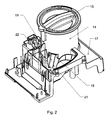
- the apparatus further comprises the powdery product dispenser 10 which comprises, in the example shown and as best seen in FIG. 2, a tank 14 of ground coffee, of generally cylindrical shape closed by a removable cover 15 and mounted in a seat 17 located inside the housing 1 of the device and supported by the internal frame of the machine.
- the tank 14 can be removably mounted in a seat 16 ( Figure 3) of the seat 17, for example by a bayonet attachment.
- the tank 14 comprises in its bottom a plurality of rotary radial blades, for example four blades, distributed along a hollow cylindrical body rotated about the vertical axis of the tank 14 by a geared motor to transfer the grind to the infusion chamber, via a dispensing orifice 18, located in the lower part of the reservoir 14, and a chute 19, as will be explained later.
- a grinding tank can for example be produced according to the description of the document FR 2,713,906 .
- the chute 19 has a half-cylindrical channel shape, inclined relative to the vertical, and opening in its lower part at a short distance (2-3cm) above the infusion chamber of the machine, the upper part of the chute being arranged at the exit of the tank 14, just below the orifice 18 for dispensing the latter.
- the chute 19 may be made of a plastic material, advantageously in one and the same piece with the seat 17.
- the machine comprises an automatic cleaning device 20 (FIG. 3) of the coffee descent chute 19 in the direction of the brewing chamber, this device comprising a wiper arm 21 that is intended to sweep the wall 22 half-cylindrical chute 19 when it is set in motion by a drive device 25 receiving the input movement of a geared motor 24.
- an automatic cleaning device 20 FIG. 3 of the coffee descent chute 19 in the direction of the brewing chamber
- this device comprising a wiper arm 21 that is intended to sweep the wall 22 half-cylindrical chute 19 when it is set in motion by a drive device 25 receiving the input movement of a geared motor 24.
- the drive device 25 receives at the input a rotational movement about a vertical axis A, as indicated by the arrow I.
- the rotational movement is produced by the vertical output shaft of a motor 27, its speed being reduced by a gear train 28 whose output is coupled to the input of the device 25.
- the drive device 25 comprises a rotary cam 30 having vertical protruding ribs 31 coming, during their driving in rotation about the axis A, in contact with the boss 36 of a slider 35, as will be explained later.
- the body of the geared motor 24 is mounted in the lower part of the seat 17 of the machine by fastening screws passing through fastening lugs 29.
- the cam 30 has a disk-shaped portion 32 supporting the protruding ribs 31, from the horizontal base of the disk 32.
- the disk-shaped portion 32 is extended vertically upwards by a hub 34.
- the hub 34 of the cam 30 is protruding relative to the seat 17 and it passes through an orifice located in the center of the seat 16 to reach the center of the reservoir 14 when the latter is mounted on the seat 17.
- the hub 34 in the form of a cross engages with the metering blades located at the inside the tank 14 and ensures their rotational drive when feeding the geared motor 24.
- the periphery of the disc-shaped portion 32 of the cam 30 (FIG. 4) is ratchet-shaped with four protuberances radial radials 33.
- a switch 40 is placed near the periphery of the cam so that each radial protrusion 33 actuates the contact 41 of the switch 40 during the rotation of the cam 30.
- the switch 40 is connected to a electronic circuit for counting the number of passages of the protuberances 33 and thus of quarter turns made by the cam 30, which circuit then controls the stopping of the cam and thus of the gear motor 24.
- the quantity of coffee grounds delivered by the The distributor device 10 is thus managed by the same cam 30, the number of passages of the radial protuberances 33 determining the quantity of ground coffee transferred to the chute 19.
- the ribs 31 of the cam 30 are arranged in the vicinity of the radial protuberances 33, but slightly offset backward in the direction of rotation of the cam so that a cleaning cycle does not start immediately after the gear motor stops.
- the ribs 31 of the cam 30 have a right prism shape, their leading face engaging the boss 36 of the slider 35 being at an angle.
- the slider 35 has a generally parallelepipedal shape and is mounted with clearance in a hollow recess 38 (better visible in FIG. 3) of corresponding shape, formed in the seat 17.
- a spring of recall (not visible in the drawings) fixed more particularly at its lug 37, the other end of the spring abuts inside the housing 38.
- the spring could be mounted at the opposite end ergot 37, which then acts as a stop.
- the slider 35 is arranged in the housing 38 so as to slide in the direction of the arrow II of Figure 4, the side walls 39 ( Figure 3) of the housing 38 forming guide rails in the sliding movement of the slider 35
- the end of the slider 35 opposite to that comprising the lug 37 may also have an elastic abutment made for example of an elastomeric material.
- the slider 35 carries the wiper arm 21 fixed with its horizontal base 23 in the center of the upper horizontal face of the slider 35.
- the wiper arm 21 comprises, in the extension of its base 23, an active portion 26 having a comparable length, or slightly lower than that of the chute 19.
- the active part 26 of the arm 21 is inclined relative to the base 23 of the arm at an angle equal to that of inclination of the chute 19.
- the wiper arm 21 is made based on of a stainless steel wire and is fixed in the slider 35 so that its active portion 26 comes into contact with the half-cylindrical wall 22 of the chute 19. Due to the elasticity of the steel wire and its mounting in contact with the chute, the active portion 26 of the wiper arm 21 bears elastically against the chute 19.
- FIGS 5 and 6 illustrate an alternative embodiment of the powder dispenser device 10 of the invention wherein the tank 14 of ground coffee is removably mounted in the seat 17 inside the housing 1 of the apparatus with a support 45
- the support 45 is a generally cylindrical part open upwards, having in the central portion of its bottom wall 46 a circular orifice 47 through which the hub 34 passes.
- the support 45 is mounted with its base in the seat 16 of the seat 17 by means of a fixing screw (not shown in the drawings) passing through an orifice 44 of the bottom wall 46.
- the bottom wall 46 also has an opening 48 cooperating with the dispensing orifice 18 of the tank 14.
- L opening 48 has a trapezoidal shape flared towards the periphery of the support 45, a shape similar to that of the dispensing orifice 18, as well as dimensions close to those of the same orifice.
- the periphery of the opening 48 has a flange 49 raised with respect to the surface of the bottom wall 46.
- the support 45 has a grinding discharge slot 50 adjacent the edge 49 of the opening 48 and located at the bottom wall 46.
- This slot 50 is formed in the bottom wall 46. , has an elongated shape slightly flared toward the center of the support 45 to increase the passage area while following, on one side, the inclination of the opening 48.
- the slot 50 communicates with the chute 19 below, the width of the latter being greater than that of the opening 48 and the adjacent slot 50.
- the slot 50 is used to evacuate the residual grind that can escape from the tank 14 and fall inside the support 45.
- the grinding is swept by the user using a brush (not shown, can be supplied with the machine) after having previously removed the reservoir 14. After sweeping, the grinding falls back into the chute 19 where it can be removed by the wiper arm 21 when the dispenser is started, such as it will be explained later.
- the user triggers the start of a coffee infusion cycle.
- the infusion cycle begins with the distribution of the ground coffee from the tank 14 through the chute 19 in the brewing chamber, the actuation of the control button feeding the geared motor 24 which rotates the cam 30.
- the hub 34 of the cam 30 drives the metering blades inside the tank 14 to push the ground coffee through the dispensing orifice 18.
- the cam 30 animates in an alternative translational movement the cursor 35, in particular when its four ribs 31 successively come into contact with the boss 36 of the slider 35.
- a rib 31 makes it possible to push the slider 35 against its return spring (which can be compression or traction according to its arrangement relative to the cursor), the latter taking its neutral position as soon as the rib 31 is no longer in contact with the boss 36 to thereby move the cursor in the opposite direction.
- its return spring which can be compression or traction according to its arrangement relative to the cursor
- the stroke or range of movement of the slider 35 corresponds to the width of the dispensing orifice 18 which is equal to the width of the chute 19, so that the wiper arm 21 can scan the entire width of the chute 19.
- the wiper arm 21 carried by the slider 35 is pushed by the return spring of the latter laterally against the wall of the chute 19.
- the rib 31 of the latter pushes the boss 36 of the slider 35 in the opposite direction, the wiper arm 21 is then brought to the diametrically opposite position inside the chute 19 from which it is brought by the spring in its initial position.
- the cam 30 has four ribs 31, which allows four return trips of the wiper arm 21 per revolution of the cam 30.
- the radial protuberances 33 of the cam 30 actuate a switch 40 which counts the number of quarter turns made by the cam 30 and thus by the hub 34 for driving the metering blades of the tank 14.
- sending a dose of ground coffee through the dispensing orifice 18 corresponds to 3/4 of a revolution of rotation of the cam or a complete revolution of rotation of the cam 30.
- This then allows the wiper arm 21 to perform three or four paths - Sweeping back of the chute when dispensing a dose of coffee in the direction of the brewing chamber.
- the geared motor 24 is stopped when the amount of ground coffee necessary to perform the controlled infusion cycle has been distributed.
- the slider 35 thus moves back and forth, as indicated by the double arrow II in FIG. 4, this movement being printed on the wiping arm 21, which thereby scans the chute 19 in the direction of its direction. width throughout the operation of the geared motor 24 and therefore throughout the coffee distribution period in the chute 19. This allows on the one hand to avoid jams in the chute during the passage of coffee grind to the infusion chamber and, on the other hand, to keep the chute always clean.
- the pressure piston descends into the chamber and compresses the grist which is then traversed by the hot infusion water from the heat block.
- the beverage then leaves through the nozzles 5, the piston goes back to its initial position, the used stock cake is expelled inside the tray 9 and the machine is ready to start a new brewing cycle.
- the same device for automatic cleaning of the chute could be used with a coffee machine using a coffee bean grinder instead of the ground coffee tank.
- a cam comprising a number different from uniformly distributed veins.
- a cleaning device dissociated from the grinding machine could be used to carry out a control sweep immediately after the passage of the coffee in the trough and preferably before the opening of the infusion chamber.
- the wiper arm could be made in the form of a flexible strip with an active portion of elastomer connected to a metal portion of attachment to the slider.
Abstract
Description
La présente invention est relative à un appareil du type distributeur automatique de boissons infusées à partir d'un dispositif distributeur de produit alimentaire pulvérulent d'infusion ou de percolation, tels le café moulu, le thé, le chocolat, etc.The present invention relates to an apparatus of the automatic vending machine type of beverage infused from a powdered infusion or percolation food dispenser device, such as ground coffee, tea, chocolate, etc.
Un appareil de préparation et distribution de boissons chaudes comprend généralement un réservoir d'eau froide, une pompe électrique, une chaudière et une tête d'infusion apte à recevoir le produit pulvérulent en vue de lui injecter l'eau chaude en provenance de la chaudière, la boisson obtenue étant ensuite orientée vers un récipient collecteur. En fin de cycle d'infusion, la tête d'infusion doit être ouverte afin de pouvoir y introduire une nouvelle dose de produit d'infusion après avoir évacué le reste de produit précédemment infusé.A device for preparing and dispensing hot drinks generally comprises a cold water tank, an electric pump, a boiler and an infusion head adapted to receive the powdery product in order to inject hot water from the boiler. the resulting drink is then directed to a collecting vessel. At the end of the infusion cycle, the infusion head must be opened in order to be able to introduce a new dose of infusion product after evacuating the rest of previously infused product.
Un tel appareil est décrit dans le document
Cet appareil comprend par ailleurs un distributeur automatique de mouture comportant un réservoir contenant la mouture, muni d'un orifice de distribution, une goulotte conduisant la mouture vers la chambre d'infusion, ainsi qu'un moyeu relié à un arbre qui met en rotation les pales du moyeu pour pousser une certaine quantité de mouture dans ladite goulotte via l'orifice de distribution lors de l'entraînement dudit arbre. Un tel distributeur automatique de mouture est décrit dans le document
En fonctionnement sur une machine à café automatique, on a quand même constaté des bourrages de café présents dans la goulotte conduisant la mouture du distributeur vers la chambre d'infusion. En effet, après la réalisation de quelques cafés successifs, la chambre d'infusion dégage de l'humidité sous forme de vapeur. La goulotte de descente de café étant située dans la proximité de la chambre d'infusion, la vapeur que la chambre dégage vient se condenser sur les parois de la goulotte, ces parois humides favorisant alors l'accrochage de la poudre de café. Le café s'accumule ainsi sur les parois de la goulotte du distributeur de mouture ce qui fait que, après quelques cycles de café, un bourrage de café peut se constituer entre celle-ci et la chambre d'infusion, bourrage qui est d'autant plus important que la mouture est fine.In operation on an automatic coffee machine, it was nevertheless found coffee jams present in the chute leading the grinding of the dispenser to the brewing chamber. Indeed, after the realization of a few successive coffees, the brewing chamber releases moisture in the form of steam. The coffee descent chute being located in the vicinity of the brewing chamber, the steam that the chamber releases condenses on the walls of the chute, these wet walls then promoting the attachment of the coffee powder. The coffee thus accumulates on the walls of the chute of the grinding machine, which means that, after a few coffee cycles, a coffee jam can form between it and the brewing chamber, which is as important as the grind is fine.
On connaît des dispositifs de nettoyage manuels de la goulotte de descente du café, par exemple à l'aide d'un pinceau, mais ces dispositifs nécessitent l'intervention de l'utilisateur.There are known manual cleaning devices of the coffee descent chute, for example with the aid of a brush, but these devices require the intervention of the user.
Par ailleurs, le document
Le but de la présente invention est de remédier aux inconvénients précités et de proposer un distributeur automatique de boissons infusées comportant un distributeur de produit pulvérulent apte à éviter, automatiquement et de manière efficace, le bourrage de produit à infuser dans la goulotte le conduisant à la chambre d'infusion.The object of the present invention is to overcome the aforementioned drawbacks and to propose a vending machine of infused beverages comprising a powdery product dispenser able to automatically and effectively prevent the stuffing of the product to be infused into the chute leading to it. brewing chamber.
Un autre but de l'invention est un distributeur automatique de boissons infusées apte à préparer une boisson de qualité, au goût frais, tout en étant sûr et fiable en fonctionnement.Another object of the invention is a vending machine of infused beverages capable of preparing a quality drink with a fresh taste, while being safe and reliable in operation.
Un autre but de l'invention est un distributeur automatique de boissons infusées comportant un dispositif de nettoyage automatique de la goulotte de descente de café qui agit simultanément au passage du café dans la goulotte.Another object of the invention is a vending machine of infused beverages comprising an automatic cleaning device of the coffee chute which simultaneously acts to the passage of coffee in the chute.
Un autre but de l'invention est un distributeur automatique de boissons infusées comportant un dispositif de nettoyage automatique de la goulotte de descente de café pouvant être réalisé de manière économique, tout en étant dissocié du groupe d'infusion.Another object of the invention is a vending machine for infused beverages comprising a device for automatically cleaning the coffee chute which can be economically produced while being dissociated from the brewing unit.
Ces buts sont atteints avec un distributeur automatique de boissons infusées à partir de produit pulvérulent comprenant:
- une chambre d'infusion,
- un dispositif distributeur de produit pulvérulent comportant un orifice de distribution communiquant avec une goulotte apte à canaliser ledit produit vers la chambre d'infusion,
- un dispositif de nettoyage automatique de la goulotte,
- an infusion chamber,
- a powdery product dispensing device comprising a dispensing orifice communicating with a chute adapted to channel said product towards the infusion chamber,
- an automatic cleaning device of the chute,
Le distributeur de produit pulvérulent peut être du type comportant un réservoir qui contient le produit à infuser et à l'intérieur duquel se trouve un moyeu à pales apte à passer une certaine quantité de produit, au travers d'un orifice de distribution, dans une goulotte qui l'achemine en proximité de la chambre d'infusion. Un tel distributeur peut également être un broyeur de grains de café qui envoie directement, au travers d'un orifice de distribution, ou par l'intermédiaire d'une chambre tampon, une certaine quantité de café dans une goulotte qui la transfère dans la chambre d'infusion. Une telle goulotte est un conduit tubulaire, ouvert ou fermé, qui est disposé généralement vertical ou incliné par rapport à la chambre d'infusion, de manière à ce que le produit pulvérulent tombe par gravité à l'intérieur de la chambre d'infusion.The powdery product dispenser may be of the type comprising a reservoir which contains the product to be infused and inside which there is a hub with blades able to pass a certain amount of product, through a dispensing orifice, in a chute which conveys it close to the chamber of infusion. Such a dispenser may also be a coffee bean crusher which directly sends, through a dispensing orifice, or through a buffer chamber, a certain quantity of coffee into a chute which transfers it into the chamber infusion. Such a chute is a tubular conduit, open or closed, which is arranged generally vertical or inclined relative to the brewing chamber, so that the powdery product falls by gravity inside the brewing chamber.
Plus particulièrement selon l'invention, la goulotte du distributeur est nettoyée automatiquement par un bras d'essuyage d'un dispositif de nettoyage automatique mis en mouvement par des moyens électromécaniques. Par moyens électromécaniques on comprend des moyens électriques d'entraînement, tels un moteur ou un électroaimant, d'un mécanisme couplé au bras d'essuyage. Un tel mécanisme comprend alors un agencement d'éléments capables de transformer l'énergie mécanique reçue, à l'entrée, de l'arbre moteur ou d'une armature de l'électroaimant en un mouvement du bras d'essuyage à l'intérieur de la goulotte, en sortie.More particularly according to the invention, the chute of the dispenser is cleaned automatically by a wiper arm of an automatic cleaning device set in motion by electromechanical means. Electromechanical means include electric drive means, such as a motor or an electromagnet, a mechanism coupled to the wiper arm. Such a mechanism then comprises an arrangement of elements capable of transforming the mechanical energy received, at the input, of the motor shaft or of a frame of the electromagnet into a movement of the wiper arm inside. chute, out.
Cette solution présente l'avantage de fonctionner automatiquement et indépendamment des autres composants de l'appareil, en effectuant une simple commande d'alimentation des moyens électromécaniques actionnant le bras d'essuyage. Cette commande peut être effectuée manuellement par l'utilisateur avant ou après avoir commandé un cycle d'infusion ou elle peut être préprogrammée dans le circuit logique du distributeur, circuit appartenant à une carte électronique de gestion du fonctionnement de l'appareil.This solution has the advantage of operating automatically and independently of the other components of the device, by performing a simple power supply control electromechanical means actuating the wiper arm. This command can be carried out manually by the user before or after having ordered an infusion cycle or it can be preprogrammed in the logic circuit of the distributor, circuit belonging to an electronic card for managing the operation of the apparatus.
Ainsi, de par son fonctionnement automatique et indépendant, les paramètres de fonctionnement du mouvement du bras d'essuyage peuvent facilement être réglés ou choisis par l'utilisateur, par exemple en fonction de la quantité de produit distribué, de la finesse de la mouture, etc.Thus, by its automatic and independent operation, the operating parameters of the movement of the wiper arm can easily be adjusted or chosen by the user, for example depending on the quantity of product dispensed, the fineness of the grind, etc.
De préférence, ledit mécanisme comprend un moteur électrique et un dispositif d'entraînement apte à transformer le mouvement rotatif de l'arbre de sortie du moteur en un mouvement alternatif du bras d'essuyage.Preferably, said mechanism comprises an electric motor and a drive device adapted to transform the rotary movement of the output shaft of the motor into a reciprocating movement of the wiper arm.
On aurait pu utiliser, par exemple, une roue à aubes entraînée en rotation par un moteur, chaque aube constituant alors un bras d'essuyage amené successivement lors de la rotation de la roue en contact avec la paroi de fond de la goulotte. On préfère toutefois un dispositif d'entraînement, par exemple du type bielle manivelle, permettant de transformer le mouvement rotatif de l'axe du moteur en un mouvement rectiligne alternatif du bras d'essuyage car on peut obtenir, avec un dispositif de structure simplifiée, un mouvement plus ample de balayage des parois de la goulotte.One could have used, for example, a paddle wheel rotated by a motor, each blade then constituting a wiper arm brought successively during the rotation of the wheel in contact with the bottom wall of the chute. However, a drive device, for example of the crank-rod type, is used which makes it possible to transform the rotary movement of the axis of the motor into a rectilinear reciprocating movement of the wiper arm because it is possible to obtain, with a simplified structure device, a wider sweeping movement of the walls of the chute.
Avantageusement, ledit moteur électrique appartient au dispositif distributeur de produit pulvérulent.Advantageously, said electric motor belongs to the powdery product dispensing device.
Ainsi, le fait d'utiliser un même moteur pour entraîner à la fois le distributeur de produit pulvérulent et le dispositif de nettoyage de la goulotte s'avère une solution très économique et de moindre encombrement permettant de construire un distributeur de boissons compact et de structure simplifiée. De surcroît, en faisant fonctionner le dispositif de nettoyage de la goulotte en même temps que le dispositif distributeur de produit pulvérulent, ceci permet d'éviter les bourrages dans la goulotte lors du passage du produit distribué vers la chambre d'infusion et, en même temps, de maintenir la goulotte toujours propre, tout en utilisant une solution simple, fiable et peu coûteuse.Thus, the fact of using the same motor to drive both the powdery product dispenser and the chute cleaning device is a very economical and space-saving solution to build a compact beverage dispenser and structure simplified. Moreover, by operating the chute cleaning device at the same time as the powdery product dispensing device, this makes it possible to avoid jams in the chute during the passage of the product dispensed to the infusion chamber and, at the same time, time, keep the chute always clean, while using a simple, reliable and inexpensive solution.
De préférence, le dispositif d'entraînement comprend une came entraînée en rotation par le moteur électrique via un train d'engrenages.Preferably, the driving device comprises a cam rotated by the electric motor via a gear train.
On aurait pu utiliser d'autres dispositifs d'entraînement du bras d'essuyage tels que, par exemple, un mécanisme utilisant un entraînement en rotation d'un excentrique solidaire de l'axe rotatif amené à coulisser dans une fente d'un secteur circulaire denté articulé coopérant, lui, avec un pignon d'entraînement en pivotement du bras d'essuyage. On préfère toutefois, pour des raisons de simplicité constructive, utiliser une came rotative dont le contour permet de transformer le mouvement de rotation du moteur en un mouvement oscillant du bras d'essuyage, le train d'engrenages permettant alors de réduire la vitesse de rotation, tout en assurant un bon couple de transmission des forces à la came et donc au bras d'essuyage. De préférence, le moto-réducteur sert également, comme le moteur électrique, à l'entraînement du dispositif distributeur de produit pulvérulent, par exemple pour la mise en rotation des meules d'un broyeur ou des pales d'un doseur de mouture.Other devices for driving the wiping arm could have been used, such as, for example, a mechanism using a rotation drive of an eccentric integral with the rotary shaft slidable in a slot of a circular sector. articulated tooth cooperating him, with a drive pinion pivoting the wiper arm. However, it is preferred, for reasons of constructive simplicity, use a rotary cam whose contour makes it possible to transform the rotational movement of the motor into an oscillating movement of the wiper arm, the gear train thus making it possible to reduce the speed of rotation, while ensuring a good pair of transmission of forces to the cam and thus to the wiper arm. Preferably, the geared motor also serves, as the electric motor, driving the powdery product dispensing device, for example for rotating grinding wheels of a grinder or the blades of a milling doser.
Avantageusement, la came entraîne le bras d'essuyage en un mouvement alternatif au contact d'au moins une paroi de la goulotte.Advantageously, the cam drives the wiper arm in a reciprocating movement in contact with at least one wall of the chute.
Le bras d'essuyage est donc amené à effectuer un mouvement oscillant au contact de la paroi de la goulotte, agissant donc sur cette paroi comme un essuie-glace pour enlever les particules de produit pulvérulent ayant tendance à adhérer à la goulotte.The wiper arm is thus made to perform an oscillating movement in contact with the wall of the chute, thus acting on this wall as a wiper to remove the particles of powdery product having a tendency to adhere to the chute.
De préférence, le bras d'essuyage effectue au moins un aller-retour, de préférence trois allers-retours, durant la période de distribution de produit pulvérulent.Preferably, the wiper arm performs at least one round trip, preferably three round trips, during the powdery product dispensing period.
Il a été constaté, lors des tests réalisés en laboratoire, qu'on obtient un nettoyage efficace de la goulotte en effectuant un aller-retour du bras d'essuyage vers la fin de la période de distribution de produit pulvérulent ou encore mieux en répartissant trois allers-retours sur la durée de cette période pour éviter les bourrages de produit lors de son passage dans la goulotte.It has been found, in laboratory tests, that an efficient cleaning of the chute is achieved by making a round-trip of the wiper arm towards the end of the powdery product distribution period or even better by dividing three back and forth over the duration of this period to avoid product jams during its passage in the chute.
Avantageusement, la came tourne autour d'un axe vertical.Advantageously, the cam rotates about a vertical axis.
Ceci permet un agencement vertical, éventuellement en parallèle, du moteur électrique, du moto-réducteur et du dispositif distributeur pour un plus faible encombrement de la machine.This allows a vertical arrangement, possibly in parallel, of the electric motor, the geared motor and the dispenser device for a smaller footprint of the machine.
De préférence, la came actionne un interrupteur de commande du dispositif distributeur de produit pulvérulent.Preferably, the cam actuates a control switch of the device powdery product dispenser.
Le profil de la came peut ainsi actionner un interrupteur de commande du démarrage et/ou de l'arrêt des meules d'un broyeur de grains de café ou des pales de dosage d'un réservoir de café moulu après un certain nombre de rotations de la came ou une fraction d'un tour de rotation de cette dernière.The profile of the cam can thus actuate a control switch for starting and / or stopping grinding wheels of a coffee bean grinder or the dosing blades of a ground coffee tank after a certain number of rotations of the cam or a fraction of a turn of the latter.
Dans un mode préféré de réalisation de l'invention, ledit dispositif distributeur comprend un réservoir de café moulu à doseur muni de pales, et la came comporte des moyens d'entraînement en rotation des pales du doseur. Dans un autre mode de réalisation de l'invention, le dispositif distributeur comprend un broyeur de grains de café, la came comportant des moyens d'entraînement en rotation de l'une des meules du broyeur.In a preferred embodiment of the invention, said dispensing device comprises a ground coffee tank equipped with blades, and the cam comprises means for rotating the blades of the metering device. In another embodiment of the invention, the dispensing device comprises a coffee bean grinder, the cam comprising means for driving in rotation one of the grinding wheels of the grinder.
Avantageusement, le bras d'essuyage est fixé à un curseur guidé en translation dans un plan perpendiculaire à l'axe de rotation de la came.Advantageously, the wiper arm is fixed to a cursor guided in translation in a plane perpendicular to the axis of rotation of the cam.
Dans une variante, le bras d'essuyage est monté pivotant autour d'une articulation située dans le voisinage de la goulotte, l'une des extrémités du bras d'essuyage venant alors au contact de la came rotative lui imprimant alors le mouvement de pivotement à l'intérieur de la goulotte.
On préfère toutefois imprimer au bras d'essuyage un mouvement de translation alternative en utilisant un curseur guidé en translation au contact du profil de la came rotative, ce mouvement assurant un meilleur balayage de la surface parcourue par le bras d'essuyage.In a variant, the wiper arm is pivotally mounted about a hinge located in the vicinity of the chute, one end of the wiper arm then coming into contact with the rotary cam, thereby imparting the pivoting movement. inside the chute.
However, it is preferred to print the wiper arm an alternative translation movement using a cursor guided in translation in contact with the profile of the rotary cam, this movement ensuring a better scan of the surface traversed by the wiper arm.
De préférence, ledit curseur est monté dans un logement moyennant un ressort de rappel, la force du ressort étant contraire à celle imprimée au curseur par la came.Preferably, said slider is mounted in a housing by means of a return spring, the force of the spring being opposite to that printed with the slider by the cam.
Ceci constitue une solution simplifiée du mécanisme d'actionnement du bras d'essuyage, les protubérances radiales de la came imprimant le mouvement aller au curseur, le mouvement retour du curseur étant assuré par un ressort de rappel.This is a simplified solution of the actuating mechanism of the wiper arm, the radial protuberances of the cam imparting the movement to go to the cursor, the return movement of the cursor being provided by a return spring.
Avantageusement, la goulotte est inclinée par rapport au plan du curseur et le bras d'essuyage suit l'inclinaison de la goulotte.Advantageously, the chute is inclined relative to the plane of the slider and the wiper arm follows the inclination of the chute.
Une goulotte inclinée forme un tremplin de déversement du café moulu, orientant le café en direction de la chambre d'infusion; pour une action efficace, le bras d'essuyage a alors une même inclinaison que la goulotte et plus particulièrement avec la paroi de cette dernière sur laquelle le bras d'essuyage est susceptible de venir en contact.An inclined chute forms a springboard for pouring ground coffee, directing the coffee towards the brewing chamber; for an effective action, the wiper arm then has the same inclination as the chute and more particularly with the wall of the latter on which the wiper arm is likely to come into contact.
De préférence, le bras d'essuyage effectue un mouvement de translation dans le sens de la largeur de la goulotte.Preferably, the wiper arm translates in the direction of the width of the chute.
Dans une variante, on aurait pu envisager un balayage de nettoyage dans le sens de la longueur de la goulotte ou de la descente du café. On a toutefois constaté qu'il était plus avantageux de réaliser un balayage dans le sens de la largeur, celui-ci nécessitant d'imprimer une amplitude moindre au bras d'essuyage.In a variant, it would have been possible to envisage a cleaning sweep in the direction of the length of the chute or the descent of the coffee. However, it has been found that it is more advantageous to perform a scan in the width direction, the latter requiring to print a smaller amplitude to the wiper arm.
Avantageusement, le bras d'essuyage est disposé près de l'orifice de distribution et l'amplitude du mouvement effectué par le bras d'essuyage est sensiblement égale à la largeur de l'orifice de distribution.Advantageously, the wiper arm is disposed near the dispensing orifice and the amplitude of the movement effected by the wiper arm is substantially equal to the width of the dispensing orifice.
L'orifice de distribution débouchant directement dans la goulotte et le bras d'essuyage étant disposé à l'entrée, cette solution permet alors un nettoyage efficace de la zone de mise en contact de la goulotte avec le produit pulvérulent assurant par la suite un bon écoulement de ce dernier.The dispensing orifice opening directly into the chute and the wiper arm being disposed at the inlet, this solution then allows effective cleaning of the contact zone of the chute with the powdery product ensuring thereafter a good flow of the latter.
De préférence, ledit bras d'essuyage est réalisé en un fil d'acier inoxydable.Preferably, said wiper arm is made of a stainless steel wire.
Un tel fil, notamment d'un diamètre inférieur à 3 mm, peut avantageusement être utilisé pour nettoyer les particules de café moulu car ces dernières n'adhèrent pas au fil. Dans une variante, on pourrait envisager de déposer un revêtement du type Téflon® sur un fil en acier ou encore le revêtir d'une matière plastique élastomère assurant alors un meilleur nettoyage des parois de la goulotte.Such a wire, in particular with a diameter of less than 3 mm, can advantageously be used to clean the ground coffee particles because the latter do not adhere to the wire. Alternatively, one might consider depositing a Teflon ® type coating on a steel wire or the coating of a plastic material elastomer then ensuring better cleaning of the walls of the chute.
Avantageusement, ledit bras d'essuyage prend appui de manière élastique contre la paroi de la goulotte.Advantageously, said wiper arm bears resiliently against the wall of the chute.
Cet appui élastique pourrait se faire par l'élasticité du bras d'essuyage lui-même et/ou en le montant à ressort au contact des parois de la goulotte afin de permettre au bras d'essuyage de mieux s'adapter au contour des parois de la goulotte.This resilient support could be done by the elasticity of the wiper arm itself and / or the spring mount in contact with the walls of the chute to allow the wiper arm to better adapt to the contour of the walls chute.
Dans une variante avantageuse de réalisation de l'invention, le dispositif distributeur comprend un réservoir de produit pulvérulent monté amovible dans un support muni d'une ouverture de passage du produit pulvérulent vers la goulotte.In an advantageous embodiment of the invention, the dispensing device comprises a powdery product reservoir removably mounted in a support provided with an opening for the passage of the powdery product towards the chute.
Le réservoir de produit pulvérulent étant monté de manière démontable ou amovible par rapport au châssis du distributeur, l'utilisateur peut alors le retirer facilement en vue de son nettoyage ou de son stockage dans un endroit frais et/ou le remplacer par un autre réservoir contenant un produit pulvérulent différent du premier.The powdery product reservoir being removably or removably mounted relative to the dispenser frame, the user can then easily remove it for cleaning or storage in a cool place and / or replace it with another container containing a powdery product different from the first.
Avantageusement, la paroi de fond du support comporte une fente d'évacuation de produit pulvérulent en direction de la goulotte.Advantageously, the bottom wall of the support comprises a discharge slot of powdery product in the direction of the chute.
Le support de réservoir amovible permet déjà de porter et guider le réservoir amovible par rapport au châssis du distributeur, ainsi que de recevoir en son fond les éventuels résidus de produit pulvérulent s'échappant du réservoir durant le fonctionnement. La fente d'évacuation de produit pulvérulent permet alors d'évacuer ces résidus vers la goulotte en dessous, le réservoir étant enlevé du support, et de garder ainsi un support propre et fonctionnel.The removable tank support already makes it possible to carry and guide the removable tank relative to the frame of the dispenser, as well as to receive at its bottom any residues of powdery product escaping from the tank during operation. The discharge slot of powdery product then allows to evacuate these residues to the chute below, the tank being removed from the support, and thus keep a clean and functional support.
L'invention sera mieux comprise à l'étude d'un mode de réalisation pris à titre nullement limitatif et illustré dans les figures annexées dans lesquelles :
- la figure 1 est une vue en perspective d'un distributeur automatique de boissons infusées selon l'invention;
- la figure 2 est une vue en perspective d'un sous-ensemble constituant du distributeur de la figure 1 illustrant plus particulièrement le dispositif distributeur de produit pulvérulent, son support et la goulotte;
- la figure 3 est une vue en perspective du sous-ensemble de la figure 2, mais où le dispositif distributeur a été enlevé de son support pour rendre mieux visible d'autres composants, dont le dispositif de nettoyage de la goulotte;
- la figure 4 est une vue en perspective du dispositif de nettoyage de la goulotte ;
- la figure 5 est une vue en perspective du dispositif distributeur selon une variante de réalisation de l'invention ;
- la figure 6 est une vue de dessus légèrement en perspective d'un support de réservoir du dispositif distributeur de la figure 5.
- FIG. 1 is a perspective view of a vending machine of infused beverages according to the invention;
- Figure 2 is a perspective view of a constituent subassembly of the dispenser of Figure 1 illustrating more particularly the powdery product dispensing device, its support and the chute;
- Figure 3 is a perspective view of the subassembly of Figure 2, but the dispensing device has been removed from its support to make more visible other components, including the trough cleaning device;
- Figure 4 is a perspective view of the chute cleaning device;
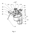
- Figure 5 is a perspective view of the dispensing device according to an alternative embodiment of the invention;
- FIG. 6 is a slightly perspective view from above of a reservoir support of the dispenser device of FIG. 5.
Le distributeur automatique de boissons infusées représenté à la figure 1 est une machine à café apte à confectionner un café espresso comprenant un boîtier 1 de forme générale parallélépipédique qui renferme les principaux éléments fonctionnels de la machine. Le boîtier 1 présente une façade comprenant un panneau de commande 2 constitué d'une série de boutons 3 agissant sur le circuit électronique de contrôle de la machine et d'un afficheur 4. La boisson confectionnée par la machine s'écoule par deux buses identiques de sortie 5 d'un bec verseur dans une tasse (non représentée) placée sur un support 6. La partie supérieure 7 du boîtier 1 renferme un distributeur de produit pulvérulent 10 comportant, dans l'exemple illustré et tel qu'il sera décrit par la suite, un réservoir de mouture de café. Un réservoir d'eau 8 est présent en la partie arrière du boîtier. Sur l'un des côtés latéraux du boîtier est agencé un bac 9 destiné à recevoir les galettes de mouture usagées en provenance de la chambre d'infusion de la machine.The brewed beverage automatic dispenser shown in FIG. 1 is a coffee machine capable of making an espresso coffee comprising a casing 1 of generally parallelepipedal shape which encloses the main functional elements of the machine. The housing 1 has a front including a
A l'intérieur du boîtier 1 est disposé un groupe d'infusion comportant une chambre d'infusion en forme de cuve cylindrique apte à recevoir une certaine quantité de café moulu au-dessus d'une paroi inférieure formant filtre pour la mouture. La chambre d'infusion est montée fixe au-dessus d'un bloc thermique, d'axe vertical, dont elle constitue le prolongement. Le bloc thermique renferme un circuit d'eau et un élément chauffant électrique et assure l'alimentation en eau chaude de la chambre d'infusion. La chambre d'infusion reçoit par ailleurs un piston presseur qui coulisse verticalement et de manière étanche dans la chambre pour compacter la mouture. Les éléments constitutifs du groupe d'infusion ne sont pas représentés sur les dessins, mais peuvent être réalisés selon la description du document
L'appareil comprend par ailleurs le distributeur de produit pulvérulent 10 qui comprend, dans l'exemple représenté et tel que mieux visible à la figure 2, un réservoir 14 de café moulu, de forme générale cylindrique fermé par un couvercle amovible 15 et monté dans un siège 17 situé à l'intérieur du boîtier 1 de l'appareil et soutenu par l'ossature interne de la machine. Le réservoir 14 peut être monté de manière amovible dans une assise 16 (figure 3) du siège 17, par exemple par une fixation à baïonnette. Le réservoir 14 comprend dans son fond une pluralité de pales radiales rotatives, par exemple quatre pales, réparties le long d'un corps cylindrique creux entraîné en rotation autour de l'axe vertical du réservoir 14 par un moto-réducteur pour transférer la mouture vers la chambre d'infusion, via un orifice de distribution 18, situé en partie inférieure du réservoir 14, et une goulotte 19, tel qu'il sera expliqué par la suite. Un tel réservoir de mouture peut par exemple être réalisé selon la description du document
Tel que visible à la figure 2, la goulotte 19 a une forme de canal demi-cylindrique, incliné par rapport à la verticale, et débouchant en sa partie inférieure à faible distance (2-3cm) au-dessus de la chambre d'infusion de la machine, la partie supérieure de la goulotte étant agencée à la sortie du réservoir 14, juste en dessous de l'orifice 18 de distribution de ce dernier. La goulotte 19 peut être réalisée en une matière plastique, avantageusement en une même pièce avec le siège 17.As shown in Figure 2, the
Selon l'invention, la machine comporte un dispositif de nettoyage automatique 20 (fig.3) de la goulotte 19 de descente de café en direction de la chambre d'infusion, ce dispositif comportant un bras d'essuyage 21 amené à balayer la paroi 22 demi-cylindrique de la goulotte 19 lorsqu'il est mis en mouvement par un dispositif d'entraînement 25 recevant le mouvement d'entrée d'un moto-réducteur 24.According to the invention, the machine comprises an automatic cleaning device 20 (FIG. 3) of the
Tel que mieux visible à la figure 4, le dispositif d'entraînement 25 reçoit à l'entrée un mouvement de rotation autour d'un axe vertical A, tel qu'indiqué par la flèche I. Le mouvement de rotation est produit par l'arbre vertical de sortie d'un moteur 27, sa vitesse étant réduite par un train d'engrenages 28 dont la sortie est couplée à l'entrée du dispositif 25. Le dispositif d'entraînement 25 comprend une came rotative 30 comportant des nervures protubérantes verticales 31 venant, lors de leur entraînement en rotation autour de l'axe A, au contact du bossage 36 d'un curseur 35, tel qu'il sera expliqué par la suite.As best seen in Figure 4, the
Le corps du moto-réducteur 24 est monté en la partie inférieure du siège 17 de la machine par des vis de fixation passant à travers des oreilles de fixation 29. La came 30 comporte une partie en forme de disque 32 supportant les nervures 31 protubérantes, à partir de la base horizontale du disque 32. La partie en forme de disque 32 est prolongée verticalement vers le haut par un moyeu 34. Tel que visible à la figure 3, le moyeu 34 de la came 30 est protubérant par rapport au siège 17 et il passe à travers un orifice situé au centre de l'assise 16 pour arriver au centre du réservoir 14 lorsque ce dernier est monté sur le siège 17. Le moyeu 34 en forme de croix vient en prise avec les pales de dosage situées à l'intérieur du réservoir 14 et assure leur entraînement en rotation lors de l'alimentation du moto-réducteur 24.The body of the geared
Par ailleurs, la périphérie de la partie en forme de disque 32 de la came 30 (figure 4) a une forme de roue à rochet en étant munie de quatre protubérances radiales 33. Un interrupteur 40 est placé à proximité de la périphérie de la came de telle sorte que chaque protubérance radiale 33 actionne le contact 41 de l'interrupteur 40 lors de la rotation de la came 30. L'interrupteur 40 est relié à un circuit électronique de comptage du nombre de passages des protubérances 33 et donc de quarts de tours effectués par la came 30, circuit qui commande ensuite l'arrêt de la came et donc du moto-réducteur 24. La quantité de mouture de café délivrée par le dispositif distributeur 10 est donc gérée par la même came 30, le nombre de passages des protubérances radiales 33 déterminant la quantité de café moulu transféré vers la goulotte 19. Les nervures 31 de la came 30 sont disposées dans la proximité des protubérances radiales 33, mais légèrement décalées en arrière dans le sens de rotation de la came de manière à ce qu'un cycle de nettoyage ne commence pas immédiatement après l'arrêt du moto-réducteur.On the other hand, the periphery of the disc-shaped
Les nervures 31 de la came 30 ont une forme de prisme droit, leur face d'attaque venant au contact du bossage 36 du curseur 35 étant en biais. Le curseur 35 a une forme générale parallélépipédique et est monté avec jeu dans un logement creux 38 (mieux visible à la figure 3) de forme correspondante, pratiqué dans le siège 17. A l'une des extrémités du curseur 35 est monté un ressort de rappel (non visible sur les dessins) fixé plus particulièrement au niveau de son ergot 37, l'autre extrémité du ressort venant en butée à l'intérieur du logement 38. A l'inverse, le ressort pourrait être monté à l'extrémité opposée de l'ergot 37, celui-ci faisant alors office de butée. Le curseur 35 est agencé dans le logement 38 de manière à pouvoir coulisser dans la direction de la flèche II de la figure 4, les parois latérales 39 (figure 3) du logement 38 formant des rails de guidage dans le mouvement de coulissement du curseur 35. L'extrémité du curseur 35 opposée à celle comportant l'ergot 37 peut également présenter une butée élastique réalisée par exemple en une matière élastomère.The
Tel que mieux visible à la figure 4, le curseur 35 porte le bras d'essuyage 21 fixé avec sa base 23 horizontale au centre de la face supérieure horizontale du curseur 35. Le bras d'essuyage 21 comporte, dans le prolongement de sa base 23, une partie active 26 ayant une longueur comparable, voire légèrement inférieure, à celle de la goulotte 19. La partie active 26 du bras 21 est inclinée par rapport à la base 23 du bras selon un angle égal à celui d'inclinaison de la goulotte 19. Le bras d'essuyage 21 est réalisé à base d'un fil en acier inoxydable et est fixé dans le curseur 35 de manière à ce que sa partie active 26 vienne en contact avec la paroi demi-cylindrique 22 de la goulotte 19. De par l'élasticité du fil en acier et de son montage au contact de la goulotte, la partie active 26 du bras d'essuyage 21 vient en appui élastique contre la goulotte 19.As best seen in FIG. 4, the
Les figures 5 et 6 illustrent une variante de réalisation du dispositif distributeur de produit pulvérulent 10 de l'invention où le réservoir 14 de café moulu est monté amovible dans le siège 17 à l'intérieur du boîtier 1 de l'appareil moyennant un support 45. Le support 45 est une pièce de forme générale cylindrique ouverte vers le haut, comportant en la partie centrale de sa paroi de fond 46 un orifice 47 circulaire traversé par le moyeu 34. Le support 45 est monté avec sa base dans l'assise 16 du siège 17 moyennant une vis de fixation (non représentée sur les dessins) passant par un orifice 44 de la paroi de fond 46. La paroi de fond 46 présente également une ouverture 48 coopérant avec l'orifice de distribution 18 du réservoir 14. L'ouverture 48 présente une forme trapézoïdale évasée vers la périphérie du support 45, forme similaire à celle de l'orifice de distribution 18, ainsi que des dimensions proches de celles du même orifice. La périphérie de l'ouverture 48 présente un rebord 49 surélevé par rapport à la surface de la paroi de fond 46.Figures 5 and 6 illustrate an alternative embodiment of the
De manière avantageuse selon cette réalisation, le support 45 présente une fente 50 d'évacuation de mouture adjacente au bord 49 de l'ouverture 48 et située au niveau de la paroi de fond 46. Cette fente 50 est pratiquée dans la paroi de fond 46, a une forme allongée légèrement évasée vers le centre du support 45 pour augmenter la surface de passage tout en suivant, sur un côté, l'inclinaison de l'ouverture 48. La fente 50 communique avec la goulotte 19 en dessous, la largeur de cette dernière étant supérieure à celle de l'ouverture 48 et de la fente 50 adjacente. La fente 50 sert à évacuer la mouture résiduelle qui peut s'échapper du réservoir 14 et tomber à l'intérieur du support 45. La mouture est balayée par l'utilisateur en utilisant un pinceau (non représenté, pouvant être fourni avec la machine) après avoir préalablement retiré le réservoir 14. Après balayage, la mouture retombe dans la goulotte 19 d'où elle peut être enlevée par le bras d'essuyage 21 lors de la mise en marche du distributeur, tel qu'il sera expliqué par la suite.Advantageously according to this embodiment, the
En fonctionnement, en actionnant l'un des boutons 3, l'utilisateur déclenche le départ d'un cycle d'infusion de café. Le cycle d'infusion commence par la distribution du café moulu depuis le réservoir 14 à travers la goulotte 19 dans la chambre d'infusion, l'actionnement du bouton de commande alimentant le moto-réducteur 24 qui met en rotation la came 30. Le moyeu 34 de la came 30 entraîne les pales de dosage à l'intérieur du réservoir 14 pour pousser la mouture de café à travers l'orifice de distribution 18. Lors de sa rotation, la came 30 anime en un mouvement de translation alternative le curseur 35, notamment lorsque ses quatre nervures 31 viennent successivement au contact du bossage 36 du curseur 35. En effet, une nervure 31 permet de pousser le curseur 35 à l'encontre de son ressort de rappel (qui peut être de compression ou de traction selon son agencement par rapport au curseur), ce dernier prenant sa position neutre dès que la nervure 31 n'est plus au contact du bossage 36 pour déplacer ainsi le curseur dans le sens contraire.In operation, by operating one of the
La course ou amplitude de mouvement du curseur 35 correspond à la largeur de l'orifice de distribution 18 qui est, elle, égale à la largeur de la goulotte 19, de manière à ce que le bras d'essuyage 21 puisse balayer toute la largeur de la goulotte 19. Ainsi, en position neutre ou de repos, le bras d'essuyage 21 porté par le curseur 35 est poussé par le ressort de rappel de ce dernier latéralement contre la paroi de la goulotte 19. Lors de la rotation de la came 30, la nervure 31 de cette dernière pousse le bossage 36 du curseur 35 dans la direction opposée, le bras d'essuyage 21 étant alors amené dans la position diamétralement opposée à l'intérieur de la goulotte 19 d'où il est ramené par le ressort dans sa position initiale. Dans l'exemple illustré, la came 30 comporte quatre nervures 31, ce qui permet quatre allers-retours du bras d'essuyage 21 par tour de rotation de la came 30.The stroke or range of movement of the
De surcroît, en tournant, les protubérances radiales 33 de la came 30 actionnent un interrupteur 40 qui compte le nombre de quarts de tours effectués par la came 30 et donc par le moyeu 34 d'entraînement des pales de dosage du réservoir 14. A titre d'exemple, l'envoi d'une dose de café moulu à travers l'orifice de distribution 18 correspond à 3/4 d'un tour de rotation de la came ou à un tour complet de rotation de la came 30. Ceci permet alors au bras d'essuyage 21 d'effectuer trois ou quatre allers-retours de balayage de la goulotte lors de la distribution d'une dose de café en direction de la chambre d'infusion. Le moto-réducteur 24 est arrêté dès lors que la quantité de mouture nécessaire pour effectuer le cycle d'infusion commandé a été distribuée.Moreover, by turning, the
Le curseur 35 effectue ainsi un mouvement de va-et-vient, comme indiqué par la double flèche II à la figure 4, ce mouvement étant imprimé au bras d'essuyage 21 qui réalise ainsi un balayage de la goulotte 19 dans le sens de sa largeur pendant toute la durée du fonctionnement du moto-réducteur 24 et donc pendant toute la période de distribution de café dans la goulotte 19. Ceci permet d'une part d'éviter les bourrages dans la goulotte lors du passage de la mouture de café vers la chambre d'infusion et, d'autre part, de maintenir la goulotte toujours propre.The
Après l'arrivée de la mouture dans la chambre d'infusion, le piston presseur descend dans la chambre et comprime la mouture qui est ensuite traversée par l'eau chaude d'infusion en provenance du bloc thermique. La boisson ressort ensuite par les buses 5, le piston remonte en sa position initiale, la galette de marc usagée est expulsée à l'intérieur du bac 9 et la machine est prête pour recommencer un nouveau cycle d'infusion.After the arrival of the grinding in the brewing chamber, the pressure piston descends into the chamber and compresses the grist which is then traversed by the hot infusion water from the heat block. The beverage then leaves through the
D'autres variantes et modes de réalisation de l'invention peuvent être envisagés sans sortir du cadre de ses revendications.Other variants and embodiments of the invention may be envisaged without departing from the scope of its claims.
Ainsi, un même dispositif de nettoyage automatique de la goulotte pourrait être utilisé avec une machine à café utilisant un broyeur de grains de café à la place du réservoir de café moulu.Thus, the same device for automatic cleaning of the chute could be used with a coffee machine using a coffee bean grinder instead of the ground coffee tank.
On pourrait utiliser, dans une variante, une came comportant un nombre différent de nervures uniformément réparties. Dans une autre variante, on pourrait envisager un nombre inférieur de nervures, par exemple une seule nervure portée par la came, mais agencée de manière à ce que le bras d'essuyage effectue un balayage uniquement à la fin du cycle de distribution de mouture dans la goulotte (par exemple en utilisant de plus des moyens de remise en position initiale de la came à chaque nouveau cycle d'infusion). Dans encore une autre variante, on pourrait utiliser un dispositif de nettoyage dissocié du distributeur de mouture pour effectuer un balayage de contrôle immédiatement après le passage du café dans la goulotte et de préférence avant l'ouverture de la chambre d'infusion.It would be possible, in a variant, to use a cam comprising a number different from uniformly distributed veins. In another variant, it would be possible to envisage a smaller number of ribs, for example a single rib carried by the cam, but arranged so that the wiper arm sweeps only at the end of the milling distribution cycle. the chute (for example by further using means for resetting the initial position of the cam at each new infusion cycle). In yet another variant, a cleaning device dissociated from the grinding machine could be used to carry out a control sweep immediately after the passage of the coffee in the trough and preferably before the opening of the infusion chamber.
Par ailleurs, le bras d'essuyage pourrait être réalisé sous forme d'une lamelle souple avec une partie active en élastomère reliée à une partie métallique de fixation au curseur.Furthermore, the wiper arm could be made in the form of a flexible strip with an active portion of elastomer connected to a metal portion of attachment to the slider.
On pourrait utiliser, dans une variante, plusieurs bras d'essuyage actionnés en translation ou en pivotement, dans le sens de la largeur de la goulotte ou celui de sa longueur.In a variant, it would be possible to use a plurality of wiping arms actuated in translation or in pivoting, in the direction of the width of the chute or that of its length.
Claims (18)
Applications Claiming Priority (1)
| Application Number | Priority Date | Filing Date | Title |
|---|---|---|---|
| FR0604088A FR2900811B1 (en) | 2006-05-09 | 2006-05-09 | AUTOMATIC DISPENSER OF INFINED BEVERAGES |
Publications (3)
| Publication Number | Publication Date |
|---|---|
| EP1854387A2 true EP1854387A2 (en) | 2007-11-14 |
| EP1854387A3 EP1854387A3 (en) | 2012-09-26 |
| EP1854387B1 EP1854387B1 (en) | 2014-02-12 |
Family
ID=37684972
Family Applications (1)
| Application Number | Title | Priority Date | Filing Date |
|---|---|---|---|
| EP07356062.5A Not-in-force EP1854387B1 (en) | 2006-05-09 | 2007-05-03 | Automatic brewed beverage dispenser |
Country Status (3)
| Country | Link |
|---|---|
| US (1) | US20070261563A1 (en) |
| EP (1) | EP1854387B1 (en) |
| FR (1) | FR2900811B1 (en) |
Cited By (2)
| Publication number | Priority date | Publication date | Assignee | Title |
|---|---|---|---|---|
| CN106993950A (en) * | 2016-01-22 | 2017-08-01 | 威斯达电器(中山)制造有限公司 | Coffee machine and its control method |
| WO2017207918A1 (en) | 2016-06-02 | 2017-12-07 | Seb S.A. | Coffee machine comprising a device for transferring coffee grounds |
Families Citing this family (9)
| Publication number | Priority date | Publication date | Assignee | Title |
|---|---|---|---|---|
| RU2555800C2 (en) * | 2009-01-29 | 2015-07-10 | Бревилл Пти Лимитед | Espresso coffee machine with control of dosing with mill |
| US10376091B2 (en) | 2011-07-21 | 2019-08-13 | Breville Pty Limited | Coffee grinder apparatus |
| US8528466B2 (en) * | 2010-02-05 | 2013-09-10 | Bobbi J Sweet | Liquid overflow platform and container for small appliances |
| JP6272772B2 (en) | 2011-11-23 | 2018-01-31 | スターバックス・コーポレイション | Beverage extraction apparatus, system and method |
| US20140131384A1 (en) * | 2012-11-12 | 2014-05-15 | Jose L MARTINEZ | Personal Cereal Dispenser |
| US20160207692A1 (en) * | 2012-11-12 | 2016-07-21 | Jose L. Martinez | Dry food dispenser |
| USD738667S1 (en) | 2013-11-20 | 2015-09-15 | Starbucks Corporation | Beverage brewing apparatus |
| WO2015077237A2 (en) | 2013-11-20 | 2015-05-28 | Starbucks Corporation D/B/A Starbucks Coffee Company | Cooking system power management |
| CA2947493C (en) * | 2014-05-07 | 2022-01-11 | Procaffe' S.P.A. | Automatic machine for preparing coffee |
Citations (2)
| Publication number | Priority date | Publication date | Assignee | Title |
|---|---|---|---|---|
| FR2713906A1 (en) * | 1993-12-20 | 1995-06-23 | Moulinex Sa | Automatic vending machine. |
| EP1654968A1 (en) * | 2004-11-09 | 2006-05-10 | Seb Sa | Automatic infusion dispenser |
Family Cites Families (9)
| Publication number | Priority date | Publication date | Assignee | Title |
|---|---|---|---|---|
| US2593151A (en) * | 1947-01-18 | 1952-04-15 | Johnson Frederick Orlo | Dispensing machine |
| US3834859A (en) * | 1973-05-21 | 1974-09-10 | Nichols Eng & Res Corp | Rabbling means and method for a furnace hearth |
| US5431027A (en) * | 1992-03-23 | 1995-07-11 | Henry Vogt Machine Co. | Flake ice-making apparatus |
| US5406882A (en) * | 1994-03-30 | 1995-04-18 | Shaanan Holdings Inc. | Brewer |
| US5519480A (en) * | 1994-11-18 | 1996-05-21 | Xerox Corporation | Retraction of cleaner backers to enable disengagement of the cleaner from the photoreceptor for image on image, multi-pass color development |
| CA2205627A1 (en) * | 1997-05-16 | 1998-11-16 | Timothy S. Mackinnon | Beverage brewer chamber assembly |
| US5823096A (en) * | 1997-10-14 | 1998-10-20 | Shih; Chun-Hong | Automatic infusing apparatus |
| US6089406A (en) * | 1999-06-01 | 2000-07-18 | Server Products | Packaged food warmer and dispenser |
| US7055536B2 (en) * | 2003-05-14 | 2006-06-06 | Roger Smiley | System and method for cleaning a feed dispenser |
-
2006
- 2006-05-09 FR FR0604088A patent/FR2900811B1/en not_active Expired - Fee Related
-
2007
- 2007-05-03 EP EP07356062.5A patent/EP1854387B1/en not_active Not-in-force
- 2007-05-09 US US11/746,231 patent/US20070261563A1/en not_active Abandoned
Patent Citations (2)
| Publication number | Priority date | Publication date | Assignee | Title |
|---|---|---|---|---|
| FR2713906A1 (en) * | 1993-12-20 | 1995-06-23 | Moulinex Sa | Automatic vending machine. |
| EP1654968A1 (en) * | 2004-11-09 | 2006-05-10 | Seb Sa | Automatic infusion dispenser |
Cited By (3)
| Publication number | Priority date | Publication date | Assignee | Title |
|---|---|---|---|---|
| CN106993950A (en) * | 2016-01-22 | 2017-08-01 | 威斯达电器(中山)制造有限公司 | Coffee machine and its control method |
| WO2017207918A1 (en) | 2016-06-02 | 2017-12-07 | Seb S.A. | Coffee machine comprising a device for transferring coffee grounds |
| US10561268B2 (en) | 2016-06-02 | 2020-02-18 | Seb S.A. | Coffee machine comprising a device for transferring coffee grounds |
Also Published As
| Publication number | Publication date |
|---|---|
| US20070261563A1 (en) | 2007-11-15 |
| FR2900811A1 (en) | 2007-11-16 |
| EP1854387B1 (en) | 2014-02-12 |
| EP1854387A3 (en) | 2012-09-26 |
| FR2900811B1 (en) | 2008-08-22 |
Similar Documents
| Publication | Publication Date | Title |
|---|---|---|
| EP1854387B1 (en) | Automatic brewed beverage dispenser | |
| EP1654968B1 (en) | Automatic infusion dispenser | |
| EP1827182B1 (en) | Automatic infused beverage dispenser comprising an infused product ejecting device | |
| EP1707088B1 (en) | Automatic coffee machine | |
| EP1304949B1 (en) | Percolator unit with mobile infusion chamber and detachable without using tools | |
| EP0237399B1 (en) | Automatic percolating machine for liquid food | |
| CH631064A5 (en) | Apparatus for preparing beverages, particularly coffee, which can be used in an automatic dispenser | |
| FR2902303A1 (en) | PULVERULENT PRODUCT DISPENSER WITH REMOVABLE TANK | |
| EP2067421A1 (en) | Automatic dispenser of ground coffee | |
| EP1872697B1 (en) | Powdery product dispenser with removable reservoirs | |
| EP0452215B1 (en) | Coffee maker | |
| WO2017207918A1 (en) | Coffee machine comprising a device for transferring coffee grounds | |
| FR2953112A1 (en) | APPARATUS FOR PREPARING INFUSIONED BEVERAGES WITH REMOVABLE RESERVE | |
| EP2378930B1 (en) | Infusion filtering device and appliance for brewing infusions fitted with such a device | |
| EP1677652B1 (en) | Improvements to percolator groups having a moving brewing chamber | |
| EP2734091B1 (en) | Soy-milk appliance using soy powder | |
| WO2001034008A1 (en) | Automatic coffee machine capable of being used for ground coffee or coffee beans | |
| EP3970575A1 (en) | Automatic coffee machine equipped with a device for draining coffee grounds | |
| FR2594671A1 (en) | Device for the automatic manufacture of food-grade drinks obtained by means of percolation | |
| FR2924589A1 (en) | Automatic ground coffee grain dispenser for use in automatic coffee machine to prepare espresso coffee, has driving cone with rotating driving vanes arranged above opening and extended in top portion of reservoir by pyramid-shaped mixer |
Legal Events
| Date | Code | Title | Description |
|---|---|---|---|
| PUAI | Public reference made under article 153(3) epc to a published international application that has entered the european phase |
Free format text: ORIGINAL CODE: 0009012 |
|
| AK | Designated contracting states |
Kind code of ref document: A2 Designated state(s): AT BE BG CH CY CZ DE DK EE ES FI FR GB GR HU IE IS IT LI LT LU LV MC MT NL PL PT RO SE SI SK TR |
|
| AX | Request for extension of the european patent |
Extension state: AL BA HR MK YU |
|
| PUAL | Search report despatched |
Free format text: ORIGINAL CODE: 0009013 |
|
| AK | Designated contracting states |
Kind code of ref document: A3 Designated state(s): AT BE BG CH CY CZ DE DK EE ES FI FR GB GR HU IE IS IT LI LT LU LV MC MT NL PL PT RO SE SI SK TR |
|
| AX | Request for extension of the european patent |
Extension state: AL BA HR MK RS |
|
| RIC1 | Information provided on ipc code assigned before grant |
Ipc: A47J 31/60 20060101AFI20120817BHEP |
|
| 17P | Request for examination filed |
Effective date: 20130308 |
|
| AKX | Designation fees paid |
Designated state(s): AT BE BG CH CY CZ DE DK EE ES FI FR GB GR HU IE IS IT LI LT LU LV MC MT NL PL PT RO SE SI SK TR |
|
| GRAP | Despatch of communication of intention to grant a patent |
Free format text: ORIGINAL CODE: EPIDOSNIGR1 |
|
| INTG | Intention to grant announced |
Effective date: 20131106 |
|
| GRAS | Grant fee paid |
Free format text: ORIGINAL CODE: EPIDOSNIGR3 |
|
| GRAA | (expected) grant |
Free format text: ORIGINAL CODE: 0009210 |
|
| AK | Designated contracting states |
Kind code of ref document: B1 Designated state(s): AT BE BG CH CY CZ DE DK EE ES FI FR GB GR HU IE IS IT LI LT LU LV MC MT NL PL PT RO SE SI SK TR |
|
| RAP1 | Party data changed (applicant data changed or rights of an application transferred) |
Owner name: SEB S.A. |
|
| REG | Reference to a national code |
Ref country code: GB Ref legal event code: FG4D Free format text: NOT ENGLISH |
|
| RIN1 | Information on inventor provided before grant (corrected) |
Inventor name: MIH, SEVERINE Inventor name: DUTERTRE, THIERRY Inventor name: MORIN, GILLES |
|
| REG | Reference to a national code |
Ref country code: CH Ref legal event code: EP |
|
| REG | Reference to a national code |
Ref country code: AT Ref legal event code: REF Ref document number: 651776 Country of ref document: AT Kind code of ref document: T Effective date: 20140215 |
|
| REG | Reference to a national code |
Ref country code: NL Ref legal event code: T3 |
|
| REG | Reference to a national code |
Ref country code: DE Ref legal event code: R096 Ref document number: 602007035051 Country of ref document: DE Effective date: 20140320 |
|
| REG | Reference to a national code |
Ref country code: IE Ref legal event code: FG4D Free format text: LANGUAGE OF EP DOCUMENT: FRENCH |
|
| REG | Reference to a national code |
Ref country code: AT Ref legal event code: MK05 Ref document number: 651776 Country of ref document: AT Kind code of ref document: T Effective date: 20140212 |
|
| REG | Reference to a national code |
Ref country code: LT Ref legal event code: MG4D |
|
| PG25 | Lapsed in a contracting state [announced via postgrant information from national office to epo] |
Ref country code: IS Free format text: LAPSE BECAUSE OF FAILURE TO SUBMIT A TRANSLATION OF THE DESCRIPTION OR TO PAY THE FEE WITHIN THE PRESCRIBED TIME-LIMIT Effective date: 20140612 Ref country code: LT Free format text: LAPSE BECAUSE OF FAILURE TO SUBMIT A TRANSLATION OF THE DESCRIPTION OR TO PAY THE FEE WITHIN THE PRESCRIBED TIME-LIMIT Effective date: 20140212 |
|
| PG25 | Lapsed in a contracting state [announced via postgrant information from national office to epo] |
Ref country code: SE Free format text: LAPSE BECAUSE OF FAILURE TO SUBMIT A TRANSLATION OF THE DESCRIPTION OR TO PAY THE FEE WITHIN THE PRESCRIBED TIME-LIMIT Effective date: 20140212 Ref country code: CY Free format text: LAPSE BECAUSE OF FAILURE TO SUBMIT A TRANSLATION OF THE DESCRIPTION OR TO PAY THE FEE WITHIN THE PRESCRIBED TIME-LIMIT Effective date: 20140212 Ref country code: ES Free format text: LAPSE BECAUSE OF FAILURE TO SUBMIT A TRANSLATION OF THE DESCRIPTION OR TO PAY THE FEE WITHIN THE PRESCRIBED TIME-LIMIT Effective date: 20140212 Ref country code: PT Free format text: LAPSE BECAUSE OF FAILURE TO SUBMIT A TRANSLATION OF THE DESCRIPTION OR TO PAY THE FEE WITHIN THE PRESCRIBED TIME-LIMIT Effective date: 20140612 Ref country code: AT Free format text: LAPSE BECAUSE OF FAILURE TO SUBMIT A TRANSLATION OF THE DESCRIPTION OR TO PAY THE FEE WITHIN THE PRESCRIBED TIME-LIMIT Effective date: 20140212 Ref country code: FI Free format text: LAPSE BECAUSE OF FAILURE TO SUBMIT A TRANSLATION OF THE DESCRIPTION OR TO PAY THE FEE WITHIN THE PRESCRIBED TIME-LIMIT Effective date: 20140212 |
|
| PG25 | Lapsed in a contracting state [announced via postgrant information from national office to epo] |
Ref country code: LV Free format text: LAPSE BECAUSE OF FAILURE TO SUBMIT A TRANSLATION OF THE DESCRIPTION OR TO PAY THE FEE WITHIN THE PRESCRIBED TIME-LIMIT Effective date: 20140212 |
|
| PG25 | Lapsed in a contracting state [announced via postgrant information from national office to epo] |
Ref country code: RO Free format text: LAPSE BECAUSE OF FAILURE TO SUBMIT A TRANSLATION OF THE DESCRIPTION OR TO PAY THE FEE WITHIN THE PRESCRIBED TIME-LIMIT Effective date: 20140212 Ref country code: CZ Free format text: LAPSE BECAUSE OF FAILURE TO SUBMIT A TRANSLATION OF THE DESCRIPTION OR TO PAY THE FEE WITHIN THE PRESCRIBED TIME-LIMIT Effective date: 20140212 Ref country code: EE Free format text: LAPSE BECAUSE OF FAILURE TO SUBMIT A TRANSLATION OF THE DESCRIPTION OR TO PAY THE FEE WITHIN THE PRESCRIBED TIME-LIMIT Effective date: 20140212 Ref country code: DK Free format text: LAPSE BECAUSE OF FAILURE TO SUBMIT A TRANSLATION OF THE DESCRIPTION OR TO PAY THE FEE WITHIN THE PRESCRIBED TIME-LIMIT Effective date: 20140212 |
|
| REG | Reference to a national code |
Ref country code: DE Ref legal event code: R097 Ref document number: 602007035051 Country of ref document: DE |
|
| PG25 | Lapsed in a contracting state [announced via postgrant information from national office to epo] |
Ref country code: SK Free format text: LAPSE BECAUSE OF FAILURE TO SUBMIT A TRANSLATION OF THE DESCRIPTION OR TO PAY THE FEE WITHIN THE PRESCRIBED TIME-LIMIT Effective date: 20140212 Ref country code: PL Free format text: LAPSE BECAUSE OF FAILURE TO SUBMIT A TRANSLATION OF THE DESCRIPTION OR TO PAY THE FEE WITHIN THE PRESCRIBED TIME-LIMIT Effective date: 20140212 |
|
| PLBE | No opposition filed within time limit |
Free format text: ORIGINAL CODE: 0009261 |
|
| STAA | Information on the status of an ep patent application or granted ep patent |
Free format text: STATUS: NO OPPOSITION FILED WITHIN TIME LIMIT |
|
| PG25 | Lapsed in a contracting state [announced via postgrant information from national office to epo] |
Ref country code: LU Free format text: LAPSE BECAUSE OF FAILURE TO SUBMIT A TRANSLATION OF THE DESCRIPTION OR TO PAY THE FEE WITHIN THE PRESCRIBED TIME-LIMIT Effective date: 20140503 |
|
| 26N | No opposition filed |
Effective date: 20141113 |
|
| PG25 | Lapsed in a contracting state [announced via postgrant information from national office to epo] |
Ref country code: MC Free format text: LAPSE BECAUSE OF FAILURE TO SUBMIT A TRANSLATION OF THE DESCRIPTION OR TO PAY THE FEE WITHIN THE PRESCRIBED TIME-LIMIT Effective date: 20140212 |
|
| REG | Reference to a national code |
Ref country code: IE Ref legal event code: MM4A |
|
| REG | Reference to a national code |
Ref country code: DE Ref legal event code: R097 Ref document number: 602007035051 Country of ref document: DE Effective date: 20141113 |
|
| PG25 | Lapsed in a contracting state [announced via postgrant information from national office to epo] |
Ref country code: IE Free format text: LAPSE BECAUSE OF NON-PAYMENT OF DUE FEES Effective date: 20140503 |
|
| PG25 | Lapsed in a contracting state [announced via postgrant information from national office to epo] |
Ref country code: SI Free format text: LAPSE BECAUSE OF FAILURE TO SUBMIT A TRANSLATION OF THE DESCRIPTION OR TO PAY THE FEE WITHIN THE PRESCRIBED TIME-LIMIT Effective date: 20140212 |
|
| PGFP | Annual fee paid to national office [announced via postgrant information from national office to epo] |
Ref country code: NL Payment date: 20150421 Year of fee payment: 9 |
|
| PGFP | Annual fee paid to national office [announced via postgrant information from national office to epo] |
Ref country code: GB Payment date: 20150518 Year of fee payment: 9 Ref country code: CH Payment date: 20150506 Year of fee payment: 9 |
|
| PGFP | Annual fee paid to national office [announced via postgrant information from national office to epo] |
Ref country code: IT Payment date: 20150512 Year of fee payment: 9 |
|
| PG25 | Lapsed in a contracting state [announced via postgrant information from national office to epo] |
Ref country code: MT Free format text: LAPSE BECAUSE OF FAILURE TO SUBMIT A TRANSLATION OF THE DESCRIPTION OR TO PAY THE FEE WITHIN THE PRESCRIBED TIME-LIMIT Effective date: 20140212 |
|
| REG | Reference to a national code |
Ref country code: FR Ref legal event code: PLFP Year of fee payment: 10 |
|
| PG25 | Lapsed in a contracting state [announced via postgrant information from national office to epo] |
Ref country code: BG Free format text: LAPSE BECAUSE OF FAILURE TO SUBMIT A TRANSLATION OF THE DESCRIPTION OR TO PAY THE FEE WITHIN THE PRESCRIBED TIME-LIMIT Effective date: 20140212 |
|
| PG25 | Lapsed in a contracting state [announced via postgrant information from national office to epo] |
Ref country code: GR Free format text: LAPSE BECAUSE OF FAILURE TO SUBMIT A TRANSLATION OF THE DESCRIPTION OR TO PAY THE FEE WITHIN THE PRESCRIBED TIME-LIMIT Effective date: 20140513 |
|
| PG25 | Lapsed in a contracting state [announced via postgrant information from national office to epo] |
Ref country code: HU Free format text: LAPSE BECAUSE OF FAILURE TO SUBMIT A TRANSLATION OF THE DESCRIPTION OR TO PAY THE FEE WITHIN THE PRESCRIBED TIME-LIMIT; INVALID AB INITIO Effective date: 20070503 Ref country code: TR Free format text: LAPSE BECAUSE OF FAILURE TO SUBMIT A TRANSLATION OF THE DESCRIPTION OR TO PAY THE FEE WITHIN THE PRESCRIBED TIME-LIMIT Effective date: 20140212 Ref country code: BE Free format text: LAPSE BECAUSE OF FAILURE TO SUBMIT A TRANSLATION OF THE DESCRIPTION OR TO PAY THE FEE WITHIN THE PRESCRIBED TIME-LIMIT Effective date: 20140531 |
|
| REG | Reference to a national code |
Ref country code: CH Ref legal event code: PL |
|
| REG | Reference to a national code |
Ref country code: NL Ref legal event code: MM Effective date: 20160601 |
|
| GBPC | Gb: european patent ceased through non-payment of renewal fee |
Effective date: 20160503 |
|
| PG25 | Lapsed in a contracting state [announced via postgrant information from national office to epo] |
Ref country code: CH Free format text: LAPSE BECAUSE OF NON-PAYMENT OF DUE FEES Effective date: 20160531 Ref country code: LI Free format text: LAPSE BECAUSE OF NON-PAYMENT OF DUE FEES Effective date: 20160531 |
|
| PG25 | Lapsed in a contracting state [announced via postgrant information from national office to epo] |
Ref country code: NL Free format text: LAPSE BECAUSE OF NON-PAYMENT OF DUE FEES Effective date: 20160601 Ref country code: IT Free format text: LAPSE BECAUSE OF NON-PAYMENT OF DUE FEES Effective date: 20160503 |
|
| REG | Reference to a national code |
Ref country code: FR Ref legal event code: PLFP Year of fee payment: 11 |
|
| PG25 | Lapsed in a contracting state [announced via postgrant information from national office to epo] |
Ref country code: GB Free format text: LAPSE BECAUSE OF NON-PAYMENT OF DUE FEES Effective date: 20160503 |
|
| REG | Reference to a national code |
Ref country code: FR Ref legal event code: CA Effective date: 20170518 |
|
| PGFP | Annual fee paid to national office [announced via postgrant information from national office to epo] |
Ref country code: FR Payment date: 20170530 Year of fee payment: 11 |
|
| PG25 | Lapsed in a contracting state [announced via postgrant information from national office to epo] |
Ref country code: FR Free format text: LAPSE BECAUSE OF NON-PAYMENT OF DUE FEES Effective date: 20180531 |
|
| PGFP | Annual fee paid to national office [announced via postgrant information from national office to epo] |
Ref country code: DE Payment date: 20200513 Year of fee payment: 14 |
|
| REG | Reference to a national code |
Ref country code: DE Ref legal event code: R119 Ref document number: 602007035051 Country of ref document: DE |
|
| PG25 | Lapsed in a contracting state [announced via postgrant information from national office to epo] |
Ref country code: DE Free format text: LAPSE BECAUSE OF NON-PAYMENT OF DUE FEES Effective date: 20211201 |