EP1854384B1 - Machine for preparing beverages by infusion of a product contained in a capsule or the like - Google Patents
Machine for preparing beverages by infusion of a product contained in a capsule or the like Download PDFInfo
- Publication number
- EP1854384B1 EP1854384B1 EP07107924A EP07107924A EP1854384B1 EP 1854384 B1 EP1854384 B1 EP 1854384B1 EP 07107924 A EP07107924 A EP 07107924A EP 07107924 A EP07107924 A EP 07107924A EP 1854384 B1 EP1854384 B1 EP 1854384B1
- Authority
- EP
- European Patent Office
- Prior art keywords
- capsule
- holder body
- machine according
- actuator member
- machine
- Prior art date
- Legal status (The legal status is an assumption and is not a legal conclusion. Google has not performed a legal analysis and makes no representation as to the accuracy of the status listed.)
- Not-in-force
Links
- 239000002775 capsule Substances 0.000 title claims abstract description 14
- 235000013361 beverage Nutrition 0.000 title claims description 10
- 238000001802 infusion Methods 0.000 title claims description 5
- 238000002360 preparation method Methods 0.000 claims abstract description 9
- XLYOFNOQVPJJNP-UHFFFAOYSA-N water Substances O XLYOFNOQVPJJNP-UHFFFAOYSA-N 0.000 claims abstract description 5
- 230000004913 activation Effects 0.000 claims 1
- 230000005484 gravity Effects 0.000 description 5
- 230000002441 reversible effect Effects 0.000 description 3
- 238000005325 percolation Methods 0.000 description 2
- 238000010276 construction Methods 0.000 description 1
Images



Classifications
-
- A—HUMAN NECESSITIES
- A47—FURNITURE; DOMESTIC ARTICLES OR APPLIANCES; COFFEE MILLS; SPICE MILLS; SUCTION CLEANERS IN GENERAL
- A47J—KITCHEN EQUIPMENT; COFFEE MILLS; SPICE MILLS; APPARATUS FOR MAKING BEVERAGES
- A47J31/00—Apparatus for making beverages
- A47J31/24—Coffee-making apparatus in which hot water is passed through the filter under pressure, i.e. in which the coffee grounds are extracted under pressure
- A47J31/34—Coffee-making apparatus in which hot water is passed through the filter under pressure, i.e. in which the coffee grounds are extracted under pressure with hot water under liquid pressure
- A47J31/36—Coffee-making apparatus in which hot water is passed through the filter under pressure, i.e. in which the coffee grounds are extracted under pressure with hot water under liquid pressure with mechanical pressure-producing means
- A47J31/3604—Coffee-making apparatus in which hot water is passed through the filter under pressure, i.e. in which the coffee grounds are extracted under pressure with hot water under liquid pressure with mechanical pressure-producing means with a mechanism arranged to move the brewing chamber between loading, infusing and ejecting stations
- A47J31/3623—Cartridges being employed
- A47J31/3633—Means to perform transfer from a loading position to an infusing position
-
- A—HUMAN NECESSITIES
- A47—FURNITURE; DOMESTIC ARTICLES OR APPLIANCES; COFFEE MILLS; SPICE MILLS; SUCTION CLEANERS IN GENERAL
- A47J—KITCHEN EQUIPMENT; COFFEE MILLS; SPICE MILLS; APPARATUS FOR MAKING BEVERAGES
- A47J31/00—Apparatus for making beverages
- A47J31/24—Coffee-making apparatus in which hot water is passed through the filter under pressure, i.e. in which the coffee grounds are extracted under pressure
- A47J31/34—Coffee-making apparatus in which hot water is passed through the filter under pressure, i.e. in which the coffee grounds are extracted under pressure with hot water under liquid pressure
- A47J31/36—Coffee-making apparatus in which hot water is passed through the filter under pressure, i.e. in which the coffee grounds are extracted under pressure with hot water under liquid pressure with mechanical pressure-producing means
- A47J31/3604—Coffee-making apparatus in which hot water is passed through the filter under pressure, i.e. in which the coffee grounds are extracted under pressure with hot water under liquid pressure with mechanical pressure-producing means with a mechanism arranged to move the brewing chamber between loading, infusing and ejecting stations
- A47J31/3623—Cartridges being employed
- A47J31/3638—Means to eject the cartridge after brewing
Definitions
- the present invention relates to a machine for preparing beverages by infusion of a product contained in a capsule, of the kind defined in the preamble of claim 1.
- capsule means, in general, a package which contains a portion of a product, for example, ground coffee, and which enables a beverage to be prepared by infusion or percolation.
- the term “capsule” therefore also means, for example, a so-called paper filter or the like.
- WO 2005/115206A1 discloses a machine of this kind wherein the capsule-holder body is translatable in a horizontal plane and the actuator member comprises a lever or handle which is rotatable about a first horizontal axis which is parallel to said plane.
- the actuator lever or handle is coupled to the capsule-holder body through a crank-link rod mechanism such that the capsule-holder is pivotable about a second axis parallel to said first axis.
- EP 1208782A1 discloses a similar machine in which the actuator member comprises a handle which is rotatable about a horizontal axis parallel to the translation plane of the capsule-holder body, between a rest position and a service position in which said handle extends behind and on the front of the machine, respectively.
- An object of the present invention is to provide an improved machine which is greatly simplified mechanically and is very simple and reliable in operation.
- a beverage-preparation machine according to the present invention is generally indicated 1 in the drawings.
- the machine 1 comprises a base 2 on which a support framework, generally indicated 3, is fixed.
- the framework 3 comprises basically two shaped plates 4 which extend facing one another in respective substantially parallel vertical planes.
- the plates 4 are shaped approximately as right-angled triangles and are fixed to the base 2 in the region of their shorter catheti.
- a hot-water dispensing head is mounted in a fixed position between the upper ends of the plates 4.
- the dispensing head which is of a conventional type, is mounted in an inclined attitude so that it is substantially perpendicular to the general direction of the oblique sides of the plates 4.
- the head 5 is connected to a heater device such as a boiler or heat-exchanger, also in conventional manner.
- a heater device such as a boiler or heat-exchanger
- the machine 1 further comprises a capsule-holder unit 6 mounted movably in the support framework 3.
- this unit comprises substantially a main body 7 to which is fixed an upper cup-shaped element 8 for holding a capsule or the like containing a product for the preparation of a beverage.
- the body 7 has, on its sides facing the plates 4, two horizontally-aligned appendages or pins which face in opposite directions and only one of which is visible, indicated 9, in the drawings. These pins extend through respective guide slots 10 which are formed in the plates 4 and which extend along axes substantially perpendicular to the plane in which the dispensing head 5 lies.
- the body 7 also has at least one further transversely projecting appendage 11 substantially parallel to the pins 9.
- the projecting appendage 11 is intended to cooperate with a portion 4a of the edge of the substantially oblique side of a plate 4 when the capsule-holder unit 6 translates away from and towards the dispensing head 5 in operation.
- a cross-member 12 fixed to the plates 4 of the support framework 3 takes the form of a plate which lies substantially parallel to the plane defined by the slots 10 in the plates 4.
- a rotatable operating unit is connected to the cross-member 12.
- the operating unit 13 is of the manually-operable type and comprises substantially a shaft 14 which extends through the plate 12 and is rotatable about an axis A substantially perpendicular to that plate.
- An actuating grip or handle 15 is connected laterally to the end of the shaft 14 that extends out of the framework 3.
- a radial arm 16 is fixed to the end of the shaft 14 that extends in the region between the plates 4 (see Figure 4a in particular); a substantially cylindrical roller 17 is fixed rotatably to the distal end of the shaft 14.
- the roller 17 extends in a substantially horizontal channel 18 provided in the lower portion of the body 7 of the capsule-holder unit 6.
- the transverse width of the channel 18, that is, the distance between its facing side walls is greater than the diameter of the roller 17, for the reasons which will become clear from the following description.
- the roller 17 can consequently adopt two different possible attitudes in the channel 18, that is, the attitude shown in Figure 1a in which it is arranged with its axis inclined to the sides or side walls of the channel 18 and in the attitude shown in Figures 2a to 3a in which its axis is substantially parallel to the side walls of the channel 18.
- the machine is assumed to be in the condition shown in Figures 1 and 1a .
- the capsule-holder unit 6 is arranged substantially vertically with the pins 9 bearing on the lower ends of the respective slots 10 in the plates 4.
- the roller 17 carried by the arm 16 of the operating unit 13 is inclined in the channel 18 of the capsule-holder unit 6.
- the cup-shaped body 8 is accessible to a user who can place a capsule of product therein for the preparation of a beverage.
- the capsule-holder unit 6 changes its attitude so as to be arranged in the position shown in Figures 2 and 2a .
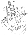
- the rotation of the shaft 14 from the position of Figure 1a brings about a pivoting movement of the capsule-holder unit 6 about the pins 9 until the projecting appendage 11 comes into abutment with the edge 4a of a plate 4 of the support framework ( Figures 2 and 2a ).
- the capsule-holder unit is aligned with the dispensing head 5 but is still spaced therefrom.
- the beverage is prepared by infusion or percolation of hot water through the capsule of product disposed in the cup-shaped element 8, in known manner.
- the user Upon completion of the beverage preparation, the user returns the machine to the initial condition of Figures 1 and 1a by acting on handle 15 so as to rotate the shaft 14 of the operating device 13 in reverse.
- the capsule-holder unit 6 is thus moved from the raised position of Figures 4 and 4a to the lowered position shown in Figures 2 and 2a . Further rotation (anti-clockwise as seen in Figure 2 ) of the handle 15 brings about pivoting of the capsule-holder unit 6 about the axis defined by the pins 9 which engage the lower ends of the associated slots 10. The capsule-holder unit 6 thus returns to the loading position.
- Figure 5 shows a variant in which the capsule-holder unit 6 is moved in the manner described above with reference to Figures 1 to 4 and 1a to 4a but by an actuating device 13 which is not manual but motorized.
- a geared motor unit 20 is fixed to the cross-member 12 and includes a reversible electric motor 21 and an associated set of reduction gears 22 the output of which is connected to the above-described shaft 14.
- that shaft has an end which extends through and beyond the reduction unit 22 and which carries two cam members 23 and 24 with which respective micro-switches 25 and 26 are associated for interrupting the supply of current to the motor 21 when the capsule-holder unit reaches the travel-limit positions.
- the machines described above may advantageously be provided with a simple system for expelling the used capsule from the cup-shaped element 8 of the capsule-holder unit 6.
- the expulsion system which is the same both for the manually-operated machine of Figures 1 -4 and 1a-4a and for the motorized machine of Figure 5 , will now be described in detail with particular reference to Figures 1a to 4a .
- the capsule-holder unit 6 comprises an ejector 30 including a rod 31 which is translatable axially in a longitudinal duct provided in the body 7 and through a hole provided in the base wall of the cup-shaped element 8.
- the end of the rod 31 which extends into the cup-shaped element 8 carries a terminal disk 32.
- a body 33 mounted between the plates 4 in the lower portion of the support framework 3 is pivotable about a horizontal axis defined by associated pins 34 (see also Figures 1 to 4 ).
- the body 33 is shaped substantially as an almost parallelepipedal block and is located substantially in a position lower than the lower end of the rod 31 of the ejector 30.
- the body 33 has a vertical groove 35 (Figures la-4a) in which the lower end of the rod 31 of the ejector 30 can be inserted at a stage of the operating cycle of the machine 1 ( Figure 2a ), as will be described further below.
- the body 33 is shaped and mounted in the framework 3 in a manner such that it tends, due to gravity, to adopt the stable attitude shown in Figures 1a, 3a and 4a , in which its lower edge bears on the base 2.
- the body can also adopt the attitude shown in Figure 2a in which it extends substantially vertically, but that attitude is potentially unstable since it tends to return by gravity towards the position shown, for example, in Figure 1a .
- the arrangement is such that, when the capsule-holder unit 6 is in the loading position of Figure 1a , the ejector 30 tends, due to gravity, to be arranged with its end disk 32 adjacent the base wall of the cup-shaped element 8. In this condition, the rod 31 is substantially vertical and is disengaged from the body 33 which, owing to gravity, adopts the stable position in which it bears on the base 2.
- the used capsule contained in the cup-shaped element 8 is thus expelled from the cavity thereof as a result of the movement of the end disk 32 of the ejector 30 relative to the cup-shaped element 8.
- a machine according to the present invention may be equipped with other expulsion systems of known type.
- a machine according to the invention may also be produced in which the used capsule is not expelled automatically at the end of the cycle but has to be removed manually by the user.
Landscapes
- Engineering & Computer Science (AREA)
- Mechanical Engineering (AREA)
- Food Science & Technology (AREA)
- Apparatus For Making Beverages (AREA)
- Non-Alcoholic Beverages (AREA)
- Infusion, Injection, And Reservoir Apparatuses (AREA)
- General Preparation And Processing Of Foods (AREA)
Abstract
Description
- The present invention relates to a machine for preparing beverages by infusion of a product contained in a capsule, of the kind defined in the preamble of
claim 1. - In this description and in the appended claims, the term "capsule" means, in general, a package which contains a portion of a product, for example, ground coffee, and which enables a beverage to be prepared by infusion or percolation. In this sense, the term "capsule" therefore also means, for example, a so-called paper filter or the like.
-
WO 2005/115206A1 discloses a machine of this kind wherein the capsule-holder body is translatable in a horizontal plane and the actuator member comprises a lever or handle which is rotatable about a first horizontal axis which is parallel to said plane. The actuator lever or handle is coupled to the capsule-holder body through a crank-link rod mechanism such that the capsule-holder is pivotable about a second axis parallel to said first axis. -
EP 1208782A1 discloses a similar machine in which the actuator member comprises a handle which is rotatable about a horizontal axis parallel to the translation plane of the capsule-holder body, between a rest position and a service position in which said handle extends behind and on the front of the machine, respectively. - An object of the present invention is to provide an improved machine which is greatly simplified mechanically and is very simple and reliable in operation.
- This and other objects are achieved according to the invention by a machine according to
claim 1. - Further characteristics and advantages of the invention will become clear from the following detailed description which is given purely by way of non-limiting example with reference to the appended drawings, in which:
-
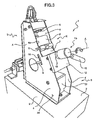
Figures 1 to 4 are perspective views of a machine according to the invention, shown in four different operative conditions, -
Figures 1a to 4a show, schematically and in side view, the machine according to the invention in the four operative positions to whichFigures 1 to 4 relate, and -
Figure 5 is a side view of a machine according to the invention in a version with motorized actuation. - A beverage-preparation machine according to the present invention is generally indicated 1 in the drawings.
- With reference to
Figures 1 to 4 , in the embodiment shown by way of example, themachine 1 comprises abase 2 on which a support framework, generally indicated 3, is fixed. Theframework 3 comprises basically twoshaped plates 4 which extend facing one another in respective substantially parallel vertical planes. - In the embodiment shown by way of example, the
plates 4 are shaped approximately as right-angled triangles and are fixed to thebase 2 in the region of their shorter catheti. - A hot-water dispensing head, generally indicated 5, is mounted in a fixed position between the upper ends of the
plates 4. The dispensing head, which is of a conventional type, is mounted in an inclined attitude so that it is substantially perpendicular to the general direction of the oblique sides of theplates 4. - The head 5 is connected to a heater device such as a boiler or heat-exchanger, also in conventional manner.
- The
machine 1 further comprises a capsule-holder unit 6 mounted movably in thesupport framework 3. In the embodiment shown, this unit comprises substantially amain body 7 to which is fixed an upper cup-shaped element 8 for holding a capsule or the like containing a product for the preparation of a beverage. Thebody 7 has, on its sides facing theplates 4, two horizontally-aligned appendages or pins which face in opposite directions and only one of which is visible, indicated 9, in the drawings. These pins extend throughrespective guide slots 10 which are formed in theplates 4 and which extend along axes substantially perpendicular to the plane in which the dispensing head 5 lies. - The
body 7 also has at least one further transversely projectingappendage 11 substantially parallel to the pins 9. As will become clearer from the following description, theprojecting appendage 11 is intended to cooperate with aportion 4a of the edge of the substantially oblique side of aplate 4 when the capsule-holder unit 6 translates away from and towards the dispensing head 5 in operation. - A
cross-member 12 fixed to theplates 4 of thesupport framework 3 takes the form of a plate which lies substantially parallel to the plane defined by theslots 10 in theplates 4. - A rotatable operating unit, generally indicated 13, is connected to the
cross-member 12. - In the embodiment shown by way of example in
Figures 1 to 4 and 1a to 4a , theoperating unit 13 is of the manually-operable type and comprises substantially ashaft 14 which extends through theplate 12 and is rotatable about an axis A substantially perpendicular to that plate. - An actuating grip or
handle 15 is connected laterally to the end of theshaft 14 that extends out of theframework 3. - With reference to
Figures 1a to 4a , aradial arm 16 is fixed to the end of theshaft 14 that extends in the region between the plates 4 (seeFigure 4a in particular); a substantiallycylindrical roller 17 is fixed rotatably to the distal end of theshaft 14. - The
roller 17 extends in a substantiallyhorizontal channel 18 provided in the lower portion of thebody 7 of the capsule-holder unit 6. As can best be seen inFigures 2a to 4a , the transverse width of thechannel 18, that is, the distance between its facing side walls, is greater than the diameter of theroller 17, for the reasons which will become clear from the following description. Theroller 17 can consequently adopt two different possible attitudes in thechannel 18, that is, the attitude shown inFigure 1a in which it is arranged with its axis inclined to the sides or side walls of thechannel 18 and in the attitude shown inFigures 2a to 3a in which its axis is substantially parallel to the side walls of thechannel 18. - The operating cycle of the
machine 1 will now be described with reference to the series ofdrawings 1 to 4 and 1a to 4a. - Initially, the machine is assumed to be in the condition shown in
Figures 1 and1a . In this condition, the capsule-holder unit 6 is arranged substantially vertically with the pins 9 bearing on the lower ends of therespective slots 10 in theplates 4. In this condition, theroller 17 carried by thearm 16 of theoperating unit 13 is inclined in thechannel 18 of the capsule-holder unit 6. The cup-shaped body 8 is accessible to a user who can place a capsule of product therein for the preparation of a beverage. - Starting from the loading position of
Figures 1 and1a , as a result of a rotation of the shaft 14 (clockwise as seen inFigure 1 ), the capsule-holder unit 6 changes its attitude so as to be arranged in the position shown inFigures 2 and2a . In fact, the rotation of theshaft 14 from the position ofFigure 1a brings about a pivoting movement of the capsule-holder unit 6 about the pins 9 until theprojecting appendage 11 comes into abutment with theedge 4a of aplate 4 of the support framework (Figures 2 and2a ). In this condition, the capsule-holder unit is aligned with the dispensing head 5 but is still spaced therefrom. - Further rotation of the
shaft 14 by means of the handle 15 (still clockwise as seen inFigure 2 ) brings about a translational movement of the capsule-holder unit towards the dispensing head 5, this translational movement being guided by the engagement of the pins 9 in theassociated slots 10 and by theprojection 11 bearing against theedge 4a which is parallel to those slots. - The translational movement of the capsule-
holder unit 6 stops when, as a result of a further rotation of theshaft 14, the condition shown inFigure 4 is reached in which the cup-shaped element 8 mates with the dispensing head 5 to define the beverage-preparation chamber therewith. - At this point, the beverage is prepared by infusion or percolation of hot water through the capsule of product disposed in the cup-
shaped element 8, in known manner. - Upon completion of the beverage preparation, the user returns the machine to the initial condition of
Figures 1 and1a by acting onhandle 15 so as to rotate theshaft 14 of theoperating device 13 in reverse. - The capsule-
holder unit 6 is thus moved from the raised position ofFigures 4 and4a to the lowered position shown inFigures 2 and2a . Further rotation (anti-clockwise as seen inFigure 2 ) of thehandle 15 brings about pivoting of the capsule-holder unit 6 about the axis defined by the pins 9 which engage the lower ends of the associatedslots 10. The capsule-holder unit 6 thus returns to the loading position. -
Figure 5 shows a variant in which the capsule-holder unit 6 is moved in the manner described above with reference toFigures 1 to 4 and 1a to 4a but by anactuating device 13 which is not manual but motorized. In the solution ofFigure 5 , a gearedmotor unit 20 is fixed to thecross-member 12 and includes a reversibleelectric motor 21 and an associated set ofreduction gears 22 the output of which is connected to the above-describedshaft 14. In the embodiment shown, that shaft has an end which extends through and beyond thereduction unit 22 and which carries twocam members motor 21 when the capsule-holder unit reaches the travel-limit positions. - The operation of the variant of
Figure 5 is similar to that described above with reference to the embodiment shown in the preceding drawings. - The machines described above may advantageously be provided with a simple system for expelling the used capsule from the cup-
shaped element 8 of the capsule-holder unit 6. The expulsion system, which is the same both for the manually-operated machine ofFigures 1 -4 and 1a-4a and for the motorized machine ofFigure 5 , will now be described in detail with particular reference toFigures 1a to 4a . - As can be seen in those drawings, the capsule-
holder unit 6 comprises anejector 30 including arod 31 which is translatable axially in a longitudinal duct provided in thebody 7 and through a hole provided in the base wall of the cup-shaped element 8. The end of therod 31 which extends into the cup-shaped element 8 carries aterminal disk 32. - A
body 33 mounted between theplates 4 in the lower portion of thesupport framework 3 is pivotable about a horizontal axis defined by associated pins 34 (see alsoFigures 1 to 4 ). - The
body 33 is shaped substantially as an almost parallelepipedal block and is located substantially in a position lower than the lower end of therod 31 of theejector 30. - In the embodiment shown, the
body 33 has a vertical groove 35 (Figures la-4a) in which the lower end of therod 31 of theejector 30 can be inserted at a stage of the operating cycle of the machine 1 (Figure 2a ), as will be described further below. - Moreover, the
body 33 is shaped and mounted in theframework 3 in a manner such that it tends, due to gravity, to adopt the stable attitude shown inFigures 1a, 3a and 4a , in which its lower edge bears on thebase 2. As will be explained below, the body can also adopt the attitude shown inFigure 2a in which it extends substantially vertically, but that attitude is potentially unstable since it tends to return by gravity towards the position shown, for example, inFigure 1a . - The arrangement is such that, when the capsule-
holder unit 6 is in the loading position ofFigure 1a , theejector 30 tends, due to gravity, to be arranged with itsend disk 32 adjacent the base wall of the cup-shaped element 8. In this condition, therod 31 is substantially vertical and is disengaged from thebody 33 which, owing to gravity, adopts the stable position in which it bears on thebase 2. - When, as a result of a rotation of the
shaft 14, the capsule-holder unit 6 moves from the position ofFigure 1a to that ofFigure 2a , therod 31 of theejector 30 interferes with the top portion of thebody 33, causing it to pivot about theaxis 34, and thelower end portion 31a of the rod is inserted in thegroove 35 of the body (Figure 2a ). - Further rotation of the
shaft 14 causes the capsule-holder unit 6 to rise from the lowered position to the raised position until it reaches the position shown inFigures 4 and4a . In this condition, therod 31 of theejector 30 is disengaged from thebody 33 which is rearranged in the rest position bearing on thebase 2. - After the preparation of the beverage, reverse rotation of the
shaft 14 brings about a downward movement of the capsule-holder unit 6 parallel to the plane defined by theguide slots 10. During this downward movement, at a certain point, thelower end 31a of therod 31 of theejector 30 comes into abutment with the top portion of thebody 33. Theejector 30 therefore stops whilst themain body 7 and the cup-shapedelement 8 continue their translational movement until the lowered position shown inFigure 3a is reached. - The used capsule contained in the cup-shaped
element 8 is thus expelled from the cavity thereof as a result of the movement of theend disk 32 of theejector 30 relative to the cup-shapedelement 8. - Further rotation (anti-clockwise as seen in
Figure 3 ) of theshaft 14 then brings about pivoting of the capsule-holder unit 6 which moves from the position ofFigure 3a to the position ofFigure 1a . During this pivoting of the capsule-holder unit, the lower end of the rod of theejector 30 is released from thebody 33 so that the ejector can descend again by gravity, readopting the attitude it had at the beginning of the cycle. - The ejector system described above is extremely simple and advantageous. However, a machine according to the present invention may be equipped with other expulsion systems of known type. A machine according to the invention may also be produced in which the used capsule is not expelled automatically at the end of the cycle but has to be removed manually by the user.
- Naturally, the principle of the invention remaining the same, the forms of embodiment and details of construction may be varied widely with respect to those described and illustrated purely by way of non-limiting example, without thereby departing from the scope of the invention as defined in the appended claims.
Claims (8)
- A machine (1) for preparing beverages by infusion of a product contained in a capsule, comprising:a support structure (3, 4) bearing a hot-water dispensing head (5),a capsule-holder body (6) which is mounted movably in the structure (3, 4) and with which guide means (9-11, 4a) are associated for allowing the capsule-holder body to translate in a plane first position in which it mates with the dispensing head (5) defining a beverage-preparation chamber therewith, and a second position in which the guide means (9-11, 4a) allow the capsule-holder body (6) to pivot about a substantially horizontal axis (9) towards a loading angular position in which said body (6) is able to receive a capsule, andoperating means (13) including an actuator member (14) which is rotatable relative to the structure (3, 4) and is connected to the capsule-holder body (6) through an eccentric mechanism (16,17) comprising an arm (16) projecting transversely from the actuator member (14) in a manner such that, starting from a condition in which the capsule-holder body (6) is in the loading position, a rotation of the actuator member (14) in a first direction bring about, in succession, a pivoting of the capsule-holder body (6) towards the second position and then movement thereof to the first position, and a rotation of the actuator member (14) in the opposite direction brings about, in succession, the return of the capsule-holder body (6) to the second position and then pivoting thereof towards the loading position;
the machine (1) being characterized in thatthe hot-water dispensing head (5) is mounted in an upper portion of the support structure (4) and the capsule-holder body (6) is movable in the operation between a first, raised position and a second, lowered position; and in thatsaid actuator member (14) is rotatable about a first axis (A) which is substantially perpendicular to the plane of translation of the capsule-holder body (6); said arm (16) being provided with a roller (17) which is engaged with clearance in a channel (18) of the capsule-holder body (6) such that when the capsule-holder body (6) is in the said second, lowered position, a rotation of the actuator member (14) in said first direction causes a corresponding rotation of the roller (17) of the eccentric mechanism (16, 17) about said axis (A) and a corresponding pivoting of the capsule-holder body (6) about a second axis perpendicular to said first axis (A). - A machine according to Claim 1 in which the guide means comprise at least one pin (9) coupled slidingly with an elongate guide (10) in a manner such that, when the pin (9) engages an end of the guide (10), the capsule-holder body (6) can pivot about the axis of the pin (9).
- A machine according to Claim 2 in which the at least one pin (9) is integral with the capsule-holder body (6) and the associated guide (10) is integral with the support structure (3, 4).
- A machine according to Claim 3 in which the guide means further comprise at least one portion (11) of the capsule-holder body (6) which is slidable along an associated guide profile (4a) of the support structure (3, 4).
- A machine according to any one of the preceding claims in which the capsule-holder body (6) is movable between the raised position and the lowered position along a path which is inclined to the vertical direction.
- A machine according to any one of the preceding claims in which an ejector device (30-35) is associated with the capsule-holder body (6) and is able to automatically expel the capsule used for the preparation of a beverage from that body (6), the ejector device comprising an ejector member (31, 32) which is movable axially relative to the capsule-holder body (6) and which cooperates with an associated reaction member (33) which is pivotable in the support structure (3, 4) between a stable position in which it is able to bring about the activation of the ejector member (31, 32) whilst the capsule-holder body (6) moves from the raised position to the lowered position, and an unstable position in which it permits de-activation of the ejector member (31, 32) and movement of the capsule-holder body (6) from the lowered position to the raised position.
- A machine according to Claim 6 in which the reaction body (33) is able to be disengaged from the ejector member (31, 32) and to return automatically to the stable position when the capsule-holder body (6) moves from the lowered position to the raised position.
- A machine according to any one of the preceding claims in which the operating means comprise a rotary motor (21) connected to the rotatable actuator member (14).
Priority Applications (1)
| Application Number | Priority Date | Filing Date | Title |
|---|---|---|---|
| PL07107924T PL1854384T3 (en) | 2006-05-12 | 2007-05-10 | Machine for preparing beverages by infusion of a product contained in a capsule or the like |
Applications Claiming Priority (1)
| Application Number | Priority Date | Filing Date | Title |
|---|---|---|---|
| IT000346A ITTO20060346A1 (en) | 2006-05-12 | 2006-05-12 | MACHINE FOR THE PREPARATION OF DRINKS BY MEANS OF THE INFUSION OF A PRODUCT CONTAINED IN A CAPSULE OR LIKE |
Publications (2)
| Publication Number | Publication Date |
|---|---|
| EP1854384A1 EP1854384A1 (en) | 2007-11-14 |
| EP1854384B1 true EP1854384B1 (en) | 2009-12-09 |
Family
ID=38283694
Family Applications (1)
| Application Number | Title | Priority Date | Filing Date |
|---|---|---|---|
| EP07107924A Not-in-force EP1854384B1 (en) | 2006-05-12 | 2007-05-10 | Machine for preparing beverages by infusion of a product contained in a capsule or the like |
Country Status (6)
| Country | Link |
|---|---|
| EP (1) | EP1854384B1 (en) |
| AT (1) | ATE451040T1 (en) |
| DE (1) | DE602007003634D1 (en) |
| ES (1) | ES2338058T3 (en) |
| IT (1) | ITTO20060346A1 (en) |
| PL (1) | PL1854384T3 (en) |
Cited By (5)
| Publication number | Priority date | Publication date | Assignee | Title |
|---|---|---|---|---|
| US9439532B2 (en) | 2014-03-11 | 2016-09-13 | Starbucks Corporation | Beverage production machines with multi-chambered basket units |
| US9504348B2 (en) | 2014-03-11 | 2016-11-29 | Starbucks Corporation | Cartridge ejection systems and methods for single-serve beverage production machines |
| US9968217B2 (en) | 2015-06-16 | 2018-05-15 | Starbucks Corporation | Beverage preparation systems with brew chamber securing mechanisms |
| US10342377B2 (en) | 2015-06-16 | 2019-07-09 | Starbucks Corporation | Beverage preparation systems with adaptable brew chambers |
| US10602874B2 (en) | 2015-06-16 | 2020-03-31 | Starbucks Corporation Dba Starbucks Coffee Company | Beverage preparation systems with brew chamber access mechanisms |
Families Citing this family (8)
| Publication number | Priority date | Publication date | Assignee | Title |
|---|---|---|---|---|
| ITTO20080311A1 (en) | 2008-04-22 | 2009-10-23 | Lavazza Luigi Spa | MACHINE FOR THE PREPARATION OF DRINKS |
| IT1392574B1 (en) | 2008-12-30 | 2012-03-09 | Lavazza Luigi Spa | PODS MACHINE FOR COFFEE PREPARATION AND OTHER HOT DRINKS AND METHOD FOR THE PREPARATION OF PODS MACHINES |
| IT1395966B1 (en) * | 2009-08-03 | 2012-11-02 | Torino Politecnico | MACHINE FOR THE PREPARATION OF DRINKS BY MEANS OF THE INFUSION OF A PRODUCT CONTAINED IN A CAPSULE OR LIKE |
| ITTO20100272A1 (en) * | 2010-04-09 | 2011-10-10 | Caffe Ghigo S R L | ESPRESSO COFFEE MACHINE AND OTHER HOT DRINKS |
| FR2960408B1 (en) * | 2010-05-25 | 2013-05-24 | Cie Mediterraneenne Des Cafes | INFUSION BEVERAGE PRODUCTION SYSTEM |
| ITTO20110819A1 (en) * | 2011-09-14 | 2013-03-15 | Lavazza Luigi Spa | DEVICE FOR THE PREPARATION OF BEVERAGES AND ITS PROCEDURE |
| ITTO20120503A1 (en) * | 2012-06-08 | 2013-12-09 | Lavazza Luigi Spa | DISPENSING UNIT FOR MACHINES FOR THE PREPARATION OF DRINKS BY CAPSULES |
| US10531762B2 (en) | 2015-02-17 | 2020-01-14 | Bedford Systems Llc | Cartridge holder for beverage machine |
Family Cites Families (2)
| Publication number | Priority date | Publication date | Assignee | Title |
|---|---|---|---|---|
| ATE274321T1 (en) | 2000-11-28 | 2004-09-15 | Nestle Sa | PERCOLATION DEVICE |
| ITTO20040351A1 (en) | 2004-05-25 | 2004-08-25 | Sgl Italia Srl | MACHINE FOR THE PERCOLATION OF A BEVERAGE STARTING FROM POWDER MATERIAL PLACED IN A CONTAINER |
-
2006
- 2006-05-12 IT IT000346A patent/ITTO20060346A1/en unknown
-
2007
- 2007-05-10 EP EP07107924A patent/EP1854384B1/en not_active Not-in-force
- 2007-05-10 DE DE602007003634T patent/DE602007003634D1/en active Active
- 2007-05-10 ES ES07107924T patent/ES2338058T3/en active Active
- 2007-05-10 AT AT07107924T patent/ATE451040T1/en active
- 2007-05-10 PL PL07107924T patent/PL1854384T3/en unknown
Cited By (6)
| Publication number | Priority date | Publication date | Assignee | Title |
|---|---|---|---|---|
| US9439532B2 (en) | 2014-03-11 | 2016-09-13 | Starbucks Corporation | Beverage production machines with multi-chambered basket units |
| US9504348B2 (en) | 2014-03-11 | 2016-11-29 | Starbucks Corporation | Cartridge ejection systems and methods for single-serve beverage production machines |
| US9999315B2 (en) | 2014-03-11 | 2018-06-19 | Starbucks Corporation | Beverage production methods with multi chambered basket units |
| US9968217B2 (en) | 2015-06-16 | 2018-05-15 | Starbucks Corporation | Beverage preparation systems with brew chamber securing mechanisms |
| US10342377B2 (en) | 2015-06-16 | 2019-07-09 | Starbucks Corporation | Beverage preparation systems with adaptable brew chambers |
| US10602874B2 (en) | 2015-06-16 | 2020-03-31 | Starbucks Corporation Dba Starbucks Coffee Company | Beverage preparation systems with brew chamber access mechanisms |
Also Published As
| Publication number | Publication date |
|---|---|
| ITTO20060346A1 (en) | 2007-11-13 |
| DE602007003634D1 (en) | 2010-01-21 |
| ATE451040T1 (en) | 2009-12-15 |
| PL1854384T3 (en) | 2010-05-31 |
| ES2338058T3 (en) | 2010-05-03 |
| EP1854384A1 (en) | 2007-11-14 |
Similar Documents
| Publication | Publication Date | Title |
|---|---|---|
| EP1854384A1 (en) | Machine for preparing beverages by infusion of a product contained in a capsule or the like | |
| EP1721553B1 (en) | Infusion assembly for beverage preparing machine | |
| US5722313A (en) | Machine for making beverages such as espresso coffee with automatic ground coffee introduction and dregs expulsion | |
| EP2405790B1 (en) | Machine for the preparation of beverages by infusion using cartridges | |
| EP2004028B1 (en) | Machine for instant preparation of beverages, in particular of coffee, by infusion of a product contained in a pod | |
| EP2461723B1 (en) | A machine for preparing beverages by infusion of a product contained in a capsule or the like | |
| CA2441475C (en) | Extracting device with integrated capsule loading system | |
| JP5918442B2 (en) | Delivery assembly for a machine for preparing a liquid product using a capsule, a machine for preparing a liquid product with a capsule, and a system and method for preparing a liquid product | |
| EP2603120B1 (en) | Device, system and method for preparing a beverage suitable for consumption from a capsule | |
| EP3223669B1 (en) | Liquid dispensing machine with manual drop stop | |
| EP3214979B1 (en) | Machine for the preparation of liquid products via capsules and method of assembly | |
| EP3738482A1 (en) | Lever-operated dispensing unit for coffee machines | |
| PT2250950E (en) | Machine for the preparation of brewed beverages | |
| CA2684941A1 (en) | Improvements in or relating to beverage preparation machines | |
| EP3192409B1 (en) | Capsule extraction mechanism | |
| EP3735158A1 (en) | Dispensing unit for espresso | |
| EP2785224B1 (en) | Tea brewing assembly | |
| EP1720136B1 (en) | Cup handling mechanism particularly for a beverage vending machine | |
| US10368684B2 (en) | Machine for the preparation of liquid products using capsules | |
| CN118986126A (en) | Coffee machine and control method thereof | |
| HK40010272A (en) | Apparatus to prepare beverages | |
| HK1109315B (en) | Infusion assembly for beverage preparing machine | |
| HK1162892B (en) | Machine for the preparation of beverages by infusion using cartridges | |
| ITNO980003U1 (en) | MECHANICAL GROUP OF MANUAL / AUTOMATIC OPERATION PARTICULARLY SUITABLE FOR THE PRODUCTION OF BEVERAGES SUCH AS ESPRESSO COFFEE AND OTHER EVENTS |
Legal Events
| Date | Code | Title | Description |
|---|---|---|---|
| PUAI | Public reference made under article 153(3) epc to a published international application that has entered the european phase |
Free format text: ORIGINAL CODE: 0009012 |
|
| AK | Designated contracting states |
Kind code of ref document: A1 Designated state(s): AT BE BG CH CY CZ DE DK EE ES FI FR GB GR HU IE IS IT LI LT LU LV MC MT NL PL PT RO SE SI SK TR |
|
| AX | Request for extension of the european patent |
Extension state: AL BA HR MK YU |
|
| 17P | Request for examination filed |
Effective date: 20071121 |
|
| 17Q | First examination report despatched |
Effective date: 20071221 |
|
| AKX | Designation fees paid |
Designated state(s): AT BE BG CH CY CZ DE DK EE ES FI FR GB GR HU IE IS IT LI LT LU LV MC MT NL PL PT RO SE SI SK TR |
|
| GRAP | Despatch of communication of intention to grant a patent |
Free format text: ORIGINAL CODE: EPIDOSNIGR1 |
|
| GRAS | Grant fee paid |
Free format text: ORIGINAL CODE: EPIDOSNIGR3 |
|
| GRAA | (expected) grant |
Free format text: ORIGINAL CODE: 0009210 |
|
| AK | Designated contracting states |
Kind code of ref document: B1 Designated state(s): AT BE BG CH CY CZ DE DK EE ES FI FR GB GR HU IE IS IT LI LT LU LV MC MT NL PL PT RO SE SI SK TR |
|
| REG | Reference to a national code |
Ref country code: GB Ref legal event code: FG4D |
|
| REG | Reference to a national code |
Ref country code: CH Ref legal event code: EP |
|
| REG | Reference to a national code |
Ref country code: IE Ref legal event code: FG4D |
|
| REF | Corresponds to: |
Ref document number: 602007003634 Country of ref document: DE Date of ref document: 20100121 Kind code of ref document: P |
|
| REG | Reference to a national code |
Ref country code: CH Ref legal event code: NV Representative=s name: JACOBACCI & PARTNERS S.P.A. |
|
| REG | Reference to a national code |
Ref country code: SE Ref legal event code: TRGR |
|
| REG | Reference to a national code |
Ref country code: NL Ref legal event code: T3 |
|
| PG25 | Lapsed in a contracting state [announced via postgrant information from national office to epo] |
Ref country code: LT Free format text: LAPSE BECAUSE OF FAILURE TO SUBMIT A TRANSLATION OF THE DESCRIPTION OR TO PAY THE FEE WITHIN THE PRESCRIBED TIME-LIMIT Effective date: 20091209 Ref country code: FI Free format text: LAPSE BECAUSE OF FAILURE TO SUBMIT A TRANSLATION OF THE DESCRIPTION OR TO PAY THE FEE WITHIN THE PRESCRIBED TIME-LIMIT Effective date: 20091209 |
|
| REG | Reference to a national code |
Ref country code: ES Ref legal event code: FG2A Ref document number: 2338058 Country of ref document: ES Kind code of ref document: T3 |
|
| LTIE | Lt: invalidation of european patent or patent extension |
Effective date: 20091209 |
|
| PG25 | Lapsed in a contracting state [announced via postgrant information from national office to epo] |
Ref country code: SI Free format text: LAPSE BECAUSE OF FAILURE TO SUBMIT A TRANSLATION OF THE DESCRIPTION OR TO PAY THE FEE WITHIN THE PRESCRIBED TIME-LIMIT Effective date: 20091209 Ref country code: LV Free format text: LAPSE BECAUSE OF FAILURE TO SUBMIT A TRANSLATION OF THE DESCRIPTION OR TO PAY THE FEE WITHIN THE PRESCRIBED TIME-LIMIT Effective date: 20091209 |
|
| REG | Reference to a national code |
Ref country code: PL Ref legal event code: T3 |
|
| PG25 | Lapsed in a contracting state [announced via postgrant information from national office to epo] |
Ref country code: RO Free format text: LAPSE BECAUSE OF FAILURE TO SUBMIT A TRANSLATION OF THE DESCRIPTION OR TO PAY THE FEE WITHIN THE PRESCRIBED TIME-LIMIT Effective date: 20091209 Ref country code: IS Free format text: LAPSE BECAUSE OF FAILURE TO SUBMIT A TRANSLATION OF THE DESCRIPTION OR TO PAY THE FEE WITHIN THE PRESCRIBED TIME-LIMIT Effective date: 20100409 Ref country code: EE Free format text: LAPSE BECAUSE OF FAILURE TO SUBMIT A TRANSLATION OF THE DESCRIPTION OR TO PAY THE FEE WITHIN THE PRESCRIBED TIME-LIMIT Effective date: 20091209 Ref country code: BG Free format text: LAPSE BECAUSE OF FAILURE TO SUBMIT A TRANSLATION OF THE DESCRIPTION OR TO PAY THE FEE WITHIN THE PRESCRIBED TIME-LIMIT Effective date: 20100309 Ref country code: PT Free format text: LAPSE BECAUSE OF FAILURE TO SUBMIT A TRANSLATION OF THE DESCRIPTION OR TO PAY THE FEE WITHIN THE PRESCRIBED TIME-LIMIT Effective date: 20100409 |
|
| PG25 | Lapsed in a contracting state [announced via postgrant information from national office to epo] |
Ref country code: CZ Free format text: LAPSE BECAUSE OF FAILURE TO SUBMIT A TRANSLATION OF THE DESCRIPTION OR TO PAY THE FEE WITHIN THE PRESCRIBED TIME-LIMIT Effective date: 20091209 Ref country code: SK Free format text: LAPSE BECAUSE OF FAILURE TO SUBMIT A TRANSLATION OF THE DESCRIPTION OR TO PAY THE FEE WITHIN THE PRESCRIBED TIME-LIMIT Effective date: 20091209 |
|
| PLBE | No opposition filed within time limit |
Free format text: ORIGINAL CODE: 0009261 |
|
| STAA | Information on the status of an ep patent application or granted ep patent |
Free format text: STATUS: NO OPPOSITION FILED WITHIN TIME LIMIT |
|
| PG25 | Lapsed in a contracting state [announced via postgrant information from national office to epo] |
Ref country code: GR Free format text: LAPSE BECAUSE OF FAILURE TO SUBMIT A TRANSLATION OF THE DESCRIPTION OR TO PAY THE FEE WITHIN THE PRESCRIBED TIME-LIMIT Effective date: 20100310 Ref country code: CY Free format text: LAPSE BECAUSE OF FAILURE TO SUBMIT A TRANSLATION OF THE DESCRIPTION OR TO PAY THE FEE WITHIN THE PRESCRIBED TIME-LIMIT Effective date: 20091209 |
|
| 26N | No opposition filed |
Effective date: 20100910 |
|
| PG25 | Lapsed in a contracting state [announced via postgrant information from national office to epo] |
Ref country code: MC Free format text: LAPSE BECAUSE OF NON-PAYMENT OF DUE FEES Effective date: 20100531 |
|
| PG25 | Lapsed in a contracting state [announced via postgrant information from national office to epo] |
Ref country code: DK Free format text: LAPSE BECAUSE OF FAILURE TO SUBMIT A TRANSLATION OF THE DESCRIPTION OR TO PAY THE FEE WITHIN THE PRESCRIBED TIME-LIMIT Effective date: 20091209 |
|
| PG25 | Lapsed in a contracting state [announced via postgrant information from national office to epo] |
Ref country code: IE Free format text: LAPSE BECAUSE OF NON-PAYMENT OF DUE FEES Effective date: 20100510 Ref country code: MT Free format text: LAPSE BECAUSE OF FAILURE TO SUBMIT A TRANSLATION OF THE DESCRIPTION OR TO PAY THE FEE WITHIN THE PRESCRIBED TIME-LIMIT Effective date: 20091209 |
|
| PGRI | Patent reinstated in contracting state [announced from national office to epo] |
Ref country code: IT Effective date: 20110501 |
|
| GBPC | Gb: european patent ceased through non-payment of renewal fee |
Effective date: 20110510 |
|
| PG25 | Lapsed in a contracting state [announced via postgrant information from national office to epo] |
Ref country code: GB Free format text: LAPSE BECAUSE OF NON-PAYMENT OF DUE FEES Effective date: 20110510 |
|
| PG25 | Lapsed in a contracting state [announced via postgrant information from national office to epo] |
Ref country code: HU Free format text: LAPSE BECAUSE OF FAILURE TO SUBMIT A TRANSLATION OF THE DESCRIPTION OR TO PAY THE FEE WITHIN THE PRESCRIBED TIME-LIMIT Effective date: 20100610 Ref country code: LU Free format text: LAPSE BECAUSE OF NON-PAYMENT OF DUE FEES Effective date: 20100510 |
|
| PG25 | Lapsed in a contracting state [announced via postgrant information from national office to epo] |
Ref country code: TR Free format text: LAPSE BECAUSE OF FAILURE TO SUBMIT A TRANSLATION OF THE DESCRIPTION OR TO PAY THE FEE WITHIN THE PRESCRIBED TIME-LIMIT Effective date: 20091209 |
|
| PGFP | Annual fee paid to national office [announced via postgrant information from national office to epo] |
Ref country code: SE Payment date: 20140523 Year of fee payment: 8 Ref country code: ES Payment date: 20140526 Year of fee payment: 8 Ref country code: AT Payment date: 20140527 Year of fee payment: 8 Ref country code: NL Payment date: 20140523 Year of fee payment: 8 Ref country code: CH Payment date: 20140521 Year of fee payment: 8 |
|
| PGFP | Annual fee paid to national office [announced via postgrant information from national office to epo] |
Ref country code: BE Payment date: 20140523 Year of fee payment: 8 Ref country code: PL Payment date: 20140402 Year of fee payment: 8 |
|
| REG | Reference to a national code |
Ref country code: CH Ref legal event code: PCAR Free format text: NEW ADDRESS: VIA LUGANETTO 3, 6962 LUGANO (CH) |
|
| REG | Reference to a national code |
Ref country code: CH Ref legal event code: PL |
|
| REG | Reference to a national code |
Ref country code: AT Ref legal event code: MM01 Ref document number: 451040 Country of ref document: AT Kind code of ref document: T Effective date: 20150510 |
|
| PG25 | Lapsed in a contracting state [announced via postgrant information from national office to epo] |
Ref country code: CH Free format text: LAPSE BECAUSE OF NON-PAYMENT OF DUE FEES Effective date: 20150531 Ref country code: LI Free format text: LAPSE BECAUSE OF NON-PAYMENT OF DUE FEES Effective date: 20150531 |
|
| REG | Reference to a national code |
Ref country code: NL Ref legal event code: MM Effective date: 20150601 |
|
| PG25 | Lapsed in a contracting state [announced via postgrant information from national office to epo] |
Ref country code: SE Free format text: LAPSE BECAUSE OF NON-PAYMENT OF DUE FEES Effective date: 20150511 Ref country code: AT Free format text: LAPSE BECAUSE OF NON-PAYMENT OF DUE FEES Effective date: 20150510 |
|
| PG25 | Lapsed in a contracting state [announced via postgrant information from national office to epo] |
Ref country code: NL Free format text: LAPSE BECAUSE OF NON-PAYMENT OF DUE FEES Effective date: 20150601 |
|
| REG | Reference to a national code |
Ref country code: FR Ref legal event code: PLFP Year of fee payment: 10 |
|
| PG25 | Lapsed in a contracting state [announced via postgrant information from national office to epo] |
Ref country code: PL Free format text: LAPSE BECAUSE OF NON-PAYMENT OF DUE FEES Effective date: 20150510 |
|
| PGFP | Annual fee paid to national office [announced via postgrant information from national office to epo] |
Ref country code: IT Payment date: 20160509 Year of fee payment: 10 Ref country code: FR Payment date: 20160525 Year of fee payment: 10 |
|
| PGFP | Annual fee paid to national office [announced via postgrant information from national office to epo] |
Ref country code: DE Payment date: 20160729 Year of fee payment: 10 |
|
| REG | Reference to a national code |
Ref country code: ES Ref legal event code: FD2A Effective date: 20161125 |
|
| PG25 | Lapsed in a contracting state [announced via postgrant information from national office to epo] |
Ref country code: ES Free format text: LAPSE BECAUSE OF NON-PAYMENT OF DUE FEES Effective date: 20150511 |
|
| REG | Reference to a national code |
Ref country code: DE Ref legal event code: R082 Ref document number: 602007003634 Country of ref document: DE Representative=s name: SCHMITT-NILSON SCHRAUD WAIBEL WOHLFROM PATENTA, DE |
|
| PG25 | Lapsed in a contracting state [announced via postgrant information from national office to epo] |
Ref country code: BE Free format text: LAPSE BECAUSE OF NON-PAYMENT OF DUE FEES Effective date: 20150531 |
|
| REG | Reference to a national code |
Ref country code: DE Ref legal event code: R119 Ref document number: 602007003634 Country of ref document: DE |
|
| REG | Reference to a national code |
Ref country code: FR Ref legal event code: ST Effective date: 20180131 |
|
| PG25 | Lapsed in a contracting state [announced via postgrant information from national office to epo] |
Ref country code: DE Free format text: LAPSE BECAUSE OF NON-PAYMENT OF DUE FEES Effective date: 20171201 |
|
| PG25 | Lapsed in a contracting state [announced via postgrant information from national office to epo] |
Ref country code: IT Free format text: LAPSE BECAUSE OF NON-PAYMENT OF DUE FEES Effective date: 20170510 Ref country code: FR Free format text: LAPSE BECAUSE OF NON-PAYMENT OF DUE FEES Effective date: 20170531 |