EP1852595B2 - Schubumkehrvorrichtung eines Flug-Triebwerkes - Google Patents
Schubumkehrvorrichtung eines Flug-Triebwerkes Download PDFInfo
- Publication number
- EP1852595B2 EP1852595B2 EP07251577.8A EP07251577A EP1852595B2 EP 1852595 B2 EP1852595 B2 EP 1852595B2 EP 07251577 A EP07251577 A EP 07251577A EP 1852595 B2 EP1852595 B2 EP 1852595B2
- Authority
- EP
- European Patent Office
- Prior art keywords
- cascade
- engine
- gas turbine
- core
- turbine engine
- Prior art date
- Legal status (The legal status is an assumption and is not a legal conclusion. Google has not performed a legal analysis and makes no representation as to the accuracy of the status listed.)
- Active
Links
Images


Classifications
-
- F—MECHANICAL ENGINEERING; LIGHTING; HEATING; WEAPONS; BLASTING
- F02—COMBUSTION ENGINES; HOT-GAS OR COMBUSTION-PRODUCT ENGINE PLANTS
- F02K—JET-PROPULSION PLANTS
- F02K1/00—Plants characterised by the form or arrangement of the jet pipe or nozzle; Jet pipes or nozzles peculiar thereto
- F02K1/54—Nozzles having means for reversing jet thrust
- F02K1/64—Reversing fan flow
- F02K1/70—Reversing fan flow using thrust reverser flaps or doors mounted on the fan housing
- F02K1/72—Reversing fan flow using thrust reverser flaps or doors mounted on the fan housing the aft end of the fan housing being movable to uncover openings in the fan housing for the reversed flow
-
- F—MECHANICAL ENGINEERING; LIGHTING; HEATING; WEAPONS; BLASTING
- F01—MACHINES OR ENGINES IN GENERAL; ENGINE PLANTS IN GENERAL; STEAM ENGINES
- F01D—NON-POSITIVE DISPLACEMENT MACHINES OR ENGINES, e.g. STEAM TURBINES
- F01D25/00—Component parts, details, or accessories, not provided for in, or of interest apart from, other groups
- F01D25/16—Arrangement of bearings; Supporting or mounting bearings in casings
- F01D25/162—Bearing supports
-
- F—MECHANICAL ENGINEERING; LIGHTING; HEATING; WEAPONS; BLASTING
- F02—COMBUSTION ENGINES; HOT-GAS OR COMBUSTION-PRODUCT ENGINE PLANTS
- F02C—GAS-TURBINE PLANTS; AIR INTAKES FOR JET-PROPULSION PLANTS; CONTROLLING FUEL SUPPLY IN AIR-BREATHING JET-PROPULSION PLANTS
- F02C7/00—Features, components parts, details or accessories, not provided for in, or of interest apart form groups F02C1/00 - F02C6/00; Air intakes for jet-propulsion plants
- F02C7/32—Arrangement, mounting, or driving, of auxiliaries
-
- F—MECHANICAL ENGINEERING; LIGHTING; HEATING; WEAPONS; BLASTING
- F05—INDEXING SCHEMES RELATING TO ENGINES OR PUMPS IN VARIOUS SUBCLASSES OF CLASSES F01-F04
- F05D—INDEXING SCHEME FOR ASPECTS RELATING TO NON-POSITIVE-DISPLACEMENT MACHINES OR ENGINES, GAS-TURBINES OR JET-PROPULSION PLANTS
- F05D2230/00—Manufacture
- F05D2230/50—Building or constructing in particular ways
- F05D2230/53—Building or constructing in particular ways by integrally manufacturing a component, e.g. by milling from a billet or one piece construction
-
- F—MECHANICAL ENGINEERING; LIGHTING; HEATING; WEAPONS; BLASTING
- F05—INDEXING SCHEMES RELATING TO ENGINES OR PUMPS IN VARIOUS SUBCLASSES OF CLASSES F01-F04
- F05D—INDEXING SCHEME FOR ASPECTS RELATING TO NON-POSITIVE-DISPLACEMENT MACHINES OR ENGINES, GAS-TURBINES OR JET-PROPULSION PLANTS
- F05D2240/00—Components
- F05D2240/10—Stators
- F05D2240/12—Fluid guiding means, e.g. vanes
- F05D2240/129—Cascades, i.e. assemblies of similar profiles acting in parallel
-
- F—MECHANICAL ENGINEERING; LIGHTING; HEATING; WEAPONS; BLASTING
- F05—INDEXING SCHEMES RELATING TO ENGINES OR PUMPS IN VARIOUS SUBCLASSES OF CLASSES F01-F04
- F05D—INDEXING SCHEME FOR ASPECTS RELATING TO NON-POSITIVE-DISPLACEMENT MACHINES OR ENGINES, GAS-TURBINES OR JET-PROPULSION PLANTS
- F05D2240/00—Components
- F05D2240/10—Stators
- F05D2240/14—Casings or housings protecting or supporting assemblies within
-
- F—MECHANICAL ENGINEERING; LIGHTING; HEATING; WEAPONS; BLASTING
- F05—INDEXING SCHEMES RELATING TO ENGINES OR PUMPS IN VARIOUS SUBCLASSES OF CLASSES F01-F04
- F05D—INDEXING SCHEME FOR ASPECTS RELATING TO NON-POSITIVE-DISPLACEMENT MACHINES OR ENGINES, GAS-TURBINES OR JET-PROPULSION PLANTS
- F05D2250/00—Geometry
- F05D2250/70—Shape
- F05D2250/75—Shape given by its similarity to a letter, e.g. T-shaped
Definitions
- the present invention relates to a thrust reverser for a gas turbine engine and in particular a thrust reverser in combination with a fan casing for reducing nacelle and pylon lengths.
- Some conventional turbo fan engines have accessories, such as a gearbox, mounted on a rear fan casing and within a surrounding nacelle.
- the nacelle comprises a thrust reverser unit, which includes an array of cascade boxes, and a bypass exhaust nozzle.
- the cascade boxes are mounted rearwardly of the rear fan casing and together with a translating cowl of the thrust reverser, mean the nacelle is particularly long.
- a pylon attaching the engine to the aircraft, is required to extend a long way forward to support the engine particularly at its front mounting point.
- One conventional front mount is located on the fan casing adjacent an array of outlet guide vanes, themselves position forward of the rear fan casing. As well as the outlet guide vanes supporting the fan casing a pair of A-frames spans between the rear fan casing and a core engine.
- This conventional thrust reverser unit is determined by the rear fan casing configuration, which is itself determined by (a) the size and number of engine accessories (e.g. gearbox and generator), (b) the position of the gearbox's radial drive and (c) a required location for the A-frames to attach to and react loads onto a suitably rigid core engine structure.
- engine accessories e.g. gearbox and generator
- European patent application EP 1286037 A1 discloses a cascade-type thrust reverser for an air duct of a turbofan engine that comprises a torque box structure, a track beam, a slider, a translating sleeve and a releasable lock mechanism.
- the thrust reverser is constructed to reduce the chance of a turbine rotor failure causing certain damage.
- European patent application EP 787895 A2 discloses a method of interconnecting the fan module of a ducted fan gas turbine aircraft engine to a core gas generator and to the aircraft itself. This obviates the exertion of bending loads on the core gas generator carcass when the fan intake experiences asymmetric aerodynamic loads.
- a gas turbine engine comprising a core engine, a fan, and a fan casing surrounding the fan and extending rearwardly to attach to an array of outlet guide vanes, said array of outlet guide vanes providing a first support for the fan casing, a cascade being rigidly attached to the fan casing, and a second support connecting the cascade to the core engine, characterised in that the second support is an A-frame.
- At least two A-frames are provided, one positioned at each of the top and bottom of the engine.
- Each A-frame comprises an apex attached to the cascade and its two ends attached to the core casing.
- each A-frame is attached to the core casing adjacent an array of vanes.
- the second support is an array of spokes and preferably the spokes are vanes.
- the cascade is annular and capable of carrying hoop stress.
- the rigid attachment is by virtue of the fan casing and cascade being a unitary structure.
- the cascade is rigidly attached to the fan casing by any one of the group comprising a bolted or a welded joint.
- the cascade is rigidly attached to the fan casing via a ramp fairing.
- the cascade is further rigidly attached to the fan casing via a torque box.
- the cascade is positioned between inner and outer translatable cowls in a stowed position and is exposed to an airflow when the translatable cowls are in a deployed position.
- the core casing is surrounded by a core fairing and engine accessories are mounted between the core casing and the core fairing.
- a ducted fan gas turbine engine generally indicated at 10 has a principal and rotational axis 11.
- the engine 10 comprises a propulsive fan 13 and a core engine 9 having, in axial flow series, an air intake 12, an intermediate pressure compressor 14, a high-pressure compressor 15, combustion equipment 16, a high-pressure turbine 17, an intermediate pressure turbine 18, a low-pressure turbine 19 and terminating with a core exhaust nozzle 20.
- a nacelle 21 generally surrounds the engine 10 and defines the intake 12, a bypass duct 22 and an exhaust nozzle 23.
- the gas turbine engine 10 works in the conventional manner so that air entering the intake 11 is accelerated by the fan 13 to produce two air flows: a first airflow A into the intermediate pressure compressor 14 and a second airflow B which passes through a bypass duct 22 to provide propulsive thrust.
- the intermediate pressure compressor 14 compresses the airflow A directed into it before delivering that air to the high pressure compressor 15 where further compression takes place.
- the compressed air exhausted from the high-pressure compressor 15 is directed into the combustion equipment 16 where it is mixed with fuel and the mixture combusted.
- the resultant hot combustion products then expand through, and thereby drive the high, intermediate and low-pressure turbines 17, 18, 19 before being exhausted through the nozzle 20 to provide additional propulsive thrust.
- the high, intermediate and low-pressure turbines 17, 18, 19 respectively drive the high and intermediate pressure compressors 15, 14 and the fan 13 by suitable interconnecting shafts.
- a centre-plug 29 is positioned within the core exhaust nozzle 20 to provide a form for the core gas flow A to expand against and to smooth its flow from the core engine.
- the centre-plug 29 extends rearward of the core nozzle's exit plane 27.
- the fan 13 is circumferentially surrounded by a structural member in the form of a fan casing 24, which is supported by an annular array of outlet guide vanes 28.
- the fan casing 24 comprises a rigid containment casing 25 and attached rearwardly thereto is a rear fan casing 26.
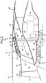
- This conventional turbo fan engine 10, having separate bypass and core engine exhaust nozzles 20, 23, is installed under an aircraft's wing 7 via a pylon 8.
- the nacelle 21 comprises two C-shaped openable doors 30, each comprising two C-shaped thrust reverser units 31, and are hinged from the aircraft's pylon 8.
- the two C-shaped thrust reverser units 31 are also attached to the engine via one or two sets of V-shaped groove/blades fixtures 32, 33 that extend around part of the nacelle and engine.
- the thrust reverser units (TRU) 31 are attached to the rear fancase 26 and the core engine's casing 34 via a stiff triangular structure 35.
- the TRU 31 comprises a number of discreet cascade boxes 36, a translating cowl 37, a translating system 38 (including an actuator and sliders), a blocking door mechanism 39, an inner fixed structure or core fairing 40 and a C-shaped bypass duct opening system (including hinges, latches and power opening system).
- the TRU 31 is normally split into left and right C-shaped ducts to enable engine removal and core engine 9 maintenance access. Hinges are defined on the pylon 8 towards the top of the C-shaped ducts and latches are defined to provide hoop continuity at the bottom of the nacelle 21 between the two C-shaped ducts.
- Each cascade box 36 attaches to a stiffening ring 41 at its aft end to provide structural support.
- a cascade box 36 comprises an array of airflow turning vanes mounted within a frame.
- the cascade boxes 36 only carry aerodynamic loads when the thrust reverser is deployed.
- the rear fancase 26 provides space for fancase mounted accessories 42 (e.g. a gearbox 43) and a load path to give axial separation between the outlet guide vane array (OGV) 28 and two A-frames (not shown in figure) at 3 and 9 O'clock positions.
- OOV outlet guide vane array
- this conventional thrust reverser unit 31 is determined by length of the rear fancase 26, which is itself determined by (a) the size of the accessories 42 (e.g. generator 44 driven off the fan case mounted accessory gearbox 43), (b) the position of the gearbox' radial drive 45 (which needs to be sufficiently aft of the OGV's 28 and forward of the outer V-groove 32) and (c) the A-frames need to react loads onto suitably strong core engine structure, in this case the intercase 34 or triangular structure 35.
- the accessories 42 e.g. generator 44 driven off the fan case mounted accessory gearbox 43
- the gearbox' radial drive 45 which needs to be sufficiently aft of the OGV's 28 and forward of the outer V-groove 32
- the A-frames need to react loads onto suitably strong core engine structure, in this case the intercase 34 or triangular structure 35.
- the length of the rear fancase 26 is disproportionately long relative to the overall length of the engine 10 and so the thrust reverser unit 31 is located considerably aft of a fan 13 which means the nacelle 21 also has substantial axial length.
- a pylon structure 46 extends forwardly from the wing 7 to a front mount 47 situated on the fan casing 24 adjacent the OGV array 28.
- a rear mount 48 is positioned on the core engine casing 34 adjacent a tail bearing housing 49 situated downstream of the low pressure compressor 19. Since the axial location of the bypass duct's nozzle 23, which is formed at the aft end of the TRU 31, is critical to engine placement on and relative to the wing 7, the engine 10 is positioned substantially forward resulting in a relatively long pylon structure 46. This prior art arrangement is therefore disadvantaged by its high over hung engine and aerodynamic loads, weight and aerodynamic drag penalties of the nacelle.
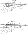
- a thrust reverser unit 50 in accordance with the present invention comprises a cascade 51 attached to the fan casing 24 and inner and outer translating cowls 52, 53.
- a conventional translating mechanism (38) is provided to drive the translating cowls 52, 53 between a stowed position 50 and a deployed position 50'.
- the translating mechanism comprises two actuators, on each side of the engine, connected to the translating cowls 52, 53.
- Cowl sliders for guiding the translating cowls 52, 53 are provided the top and bottom of the nacelle 21, in a similar manner to a conventional TRU.
- the translating cowls 52, 53 are each part of C-shaped ducts (not shown) that are openable in conventional manner via hinges positioned at the top of the engine 10 or on the pylon 8.
- the cascade 51 is rigidly attached to the fan casing 24, adjacent the stiff OGV array 28, via a ramp fairing 54, which is aerodynamically shaped to provide smooth airflow into the cascade 51 during reverse thrust operation.
- a stiff torque box 55 is secured to an outer part of the ramp fairing 54 from the fan casing 24.
- the fan casing 24, torque box 55, ramp fairing 54 and cascade box 51 are all bolted together, however, they may also be welded together.
- the cascade 51 may be a unitary member with the fan casing 24.
- the fan casing 24 must be rigidly supported so that it can transfer aerodynamic loads from the inlet 12 as well as other engine loads such as those encountered during thrust reversing.
- a second support 56 is provided and which spans between the core casing 34 and the cascade 51.
- the second support is a pair of A-frames 56 one positioned at the top or 12 O'clock position and the other is positioned at the bottom or 6 O'clock position of the engine 10.
- the A-frames 56 are positioned at the top and bottom of the engine, where there is space between ends of the C-shaped ducts, and which positioning advantageously does not interfere with the translating cowls 52, 53.
- each A-frame 56 is attached to the cascade 51 while the two ends 59 are spaced apart on the core casing 34 adjacent an array of vanes 57 or other stiff structure.
- This part of the core casing 34 is sometimes referred to as an intercase and is typically the part between the intermediate and high pressure compressors 14, 15.
- the second support 56 may comprise an array of spokes that are preferably configured as aerodynamic vanes 56'' (shown dashed in Figure 2 ).
- the vanes 56" may be arcuate to further direct bypass airflow.
- the vanes 56" may also be arranged such that they have a tangential angle. This tangential angle provides additional bracing for engine torque loads.
- the cascade 51 is an annular structure and is therefore inherently stiff. Although preferably a monolithic annular structure, the cascade 51 may be fabricated from a number of circumferential segments bolted or welded together. It should be appreciated that the cascade 51 carries substantial hoop stresses as well as axial, vertical and torque loads.
- the cascade 51 comprises an array of airflow turning vanes 60 mounted within a stiff frame 61. Stiffenning ribs 62 separate each axial row of vanes 60.
- the cascade 51 is a particularly deep structure extending between the inner cowl 52 and outer cowl 53.
- the cascade 51 extends substantially from adjacent the inner cowl 52 to adjacent the outer cowl 53.
- the torque box 55 is shown as attaching to the radially outermost part of the cascade 51, but may be attached part way along the radial depth of the cascade 51.
- This cascade 51 is advantaged as it provides greater turning for the diverted bypass airflow B' and improved stopping distance of the aircraft.
- This cascade also is particularly rigid by virtue of its deeper section thickness.
- the cascade 51 is positioned in a radially outward part of the space between inner and outer cowls 52, 53. This enables the translating inner cowl 52 to comprise a blocker member 62 for improved diversion of the bypass airflow B through the cascade 51.
- Access to the core engine 9 and the accessories 42 is achieved by deploying the thrust reverser unit 50' and rotating open the translating cowls 52, 53.
- the core fairing 40 which is hinged independently, is then rotated open.
- individual access panels may be provided and readily removed.
- a TRU including bypass duct blocker doors is provided and one such design is described in the Applicant's co-pending UK patent application GB 0606982.7 .
Landscapes
- Engineering & Computer Science (AREA)
- Chemical & Material Sciences (AREA)
- Combustion & Propulsion (AREA)
- Mechanical Engineering (AREA)
- General Engineering & Computer Science (AREA)
- Structures Of Non-Positive Displacement Pumps (AREA)
- Turbine Rotor Nozzle Sealing (AREA)
Claims (13)
- Gasturbinentriebwerk (10), das ein Kerntriebwerk (9), einen Lüfter (13), und ein Lüftergehäuse (24) umfasst, das den Lüfter (13) umgibt und das sich nach hinten erstreckt, um an einer Reihe von Auslassführungsschaufeln (28) befestigt zu werden, wobei die Reihe von Auslassführungsschaufeln (28) einen ersten Träger für das Lüftergehäuse, eine Kaskade (51), die starr am Lüftergehäuse (24) befestigt ist, einen zweiten Träger (56), der die Kaskade (51) mit dem Kerntriebwerk (9) verbindet, dadurch gekennzeichnet, dass der zweite Träger (56) ein A-Rahmen (56') ist, der einen Scheitelpunkt (58), der an der Kaskade (51) befestigt ist, und zwei Enden (59) umfasst, die an einem Kerngehäuse (34) des Kerntriebwerks (9) befestigt sind, bereitstellen.
- Gasturbinentriebwerk (10) nach Anspruch 1, wobei der zweite Träger (56) mindestens zwei A-Rahmen (56') umfasst, wobei einer an jeder der Unter- und Oberseite des Triebwerks (10) positioniert ist.
- Gasturbinentriebwerk (10) nach Anspruch 2, wobei jeder A-Rahmen (56') einen Scheitelpunkt (58), der an der Kaskade (51) befestigt ist, und zwei Enden (59) umfasst, die am Kerngehäuse (34) befestigt sind.
- Gasturbinentriebwerk (10) nach einem der Ansprüche 1 oder 3, wobei jeder A-Rahmen (56') am Kerngehäuse befestigt ist, das benachbart zu einer Reihe von Schaufeln (57) liegt.
- Gasturbinentriebwerk (10) nach einem der Ansprüche 1 bis 4, wobei die Kaskade (51) ringförmig ist und fähig ist, Umfangsspannung zu tragen.
- Gasturbinentriebwerk (10) nach einem der Ansprüche 1 bis 5, wobei die starre Befestigung aufgrund der einstückigen Struktur des Lüftergehäuses (24) und der Kaskade (51) ist.
- Gasturbinentriebwerk (10) nach einem der Ansprüche 1 bis 6, wobei die Kaskade (51) durch eine der Gruppe, die eine Schraub- oder Schweißverbindung umfasst, starr am Lüftergehäuse (24) befestigt ist.
- Gasturbinentriebwerk (10) nach einem der Ansprüche 1 bis 7, wobei die Kaskade (51) über eine Rampenverkleidung (54) starr am Lüftergehäuse (24) befestigt ist.
- Gasturbinentriebwerk (10) nach einem der Ansprüche 1 bis 8, wobei die Kaskade (51) ferner über einen Drehmomentkasten (55) starr am Lüftergehäuse (24) befestigt ist.
- Gasturbinentriebwerk (10) nach einem der Ansprüche 1 bis 9, wobei die Kaskade (51) zwischen einer inneren und äußeren verschiebbaren Haube (52, 53) in einer verstauten Position positioniert ist und einem Luftstrom B ausgesetzt ist, wenn die verschiebbaren Hauben (52, 53) in einer Einsatz-Position sind.
- Gasturbinentriebwerk (10) nach Anspruch 10, wobei die Kaskade (51) in einem radialen äußeren Teil eines Raums zwischen der inneren und äußeren Haube (52, 53) positioniert ist.
- Gasturbinentriebwerk (10) nach Anspruch 10, wobei sich die Kaskade (51) im Wesentlichen von benachbart zur inneren Haube (52) zu benachbart zur äußeren Haube (53) erstreckt.
- Gasturbinentriebwerk (10) nach einem der Ansprüche 1 bis 12, wobei das Kerngehäuse (34) von einer Kernverkleidung (40) umgeben ist und Triebwerkhilfsmittel zwischen dem Kerngehäuse (34) und der Kernverkleidung (40) gelagert sind.
Applications Claiming Priority (1)
| Application Number | Priority Date | Filing Date | Title |
|---|---|---|---|
| GBGB0608985.8A GB0608985D0 (en) | 2006-05-06 | 2006-05-06 | Aeroengine thrust reverser |
Publications (4)
| Publication Number | Publication Date |
|---|---|
| EP1852595A2 EP1852595A2 (de) | 2007-11-07 |
| EP1852595A3 EP1852595A3 (de) | 2017-11-01 |
| EP1852595B1 EP1852595B1 (de) | 2018-06-20 |
| EP1852595B2 true EP1852595B2 (de) | 2021-08-18 |
Family
ID=36604061
Family Applications (1)
| Application Number | Title | Priority Date | Filing Date |
|---|---|---|---|
| EP07251577.8A Active EP1852595B2 (de) | 2006-05-06 | 2007-04-12 | Schubumkehrvorrichtung eines Flug-Triebwerkes |
Country Status (3)
| Country | Link |
|---|---|
| US (1) | US7866142B2 (de) |
| EP (1) | EP1852595B2 (de) |
| GB (1) | GB0608985D0 (de) |
Families Citing this family (39)
| Publication number | Priority date | Publication date | Assignee | Title |
|---|---|---|---|---|
| FR2849113B1 (fr) * | 2002-12-24 | 2005-02-04 | Hurel Hispano | Inverseur de poussee a grilles de deflection optimisees |
| GB0616740D0 (en) * | 2006-08-24 | 2006-10-04 | Short Brothers Plc | Aircraft engine thrust reverser |
| US9759087B2 (en) | 2007-08-08 | 2017-09-12 | Rohr, Inc. | Translating variable area fan nozzle providing an upstream bypass flow exit |
| EP2578864B1 (de) * | 2007-08-08 | 2014-09-24 | Rohr, Inc. | Veränderliche Gebläsedüse mit Bypass-Strom |
| FR2938878B1 (fr) * | 2008-11-26 | 2013-11-08 | Aircelle Sa | Inverseur de poussee pour nacelle de turboreacteur a double flux |
| DE102009033755A1 (de) * | 2009-07-17 | 2011-01-20 | Rolls-Royce Deutschland Ltd & Co Kg | Turbofantriebwerk |
| FR2954410B1 (fr) | 2009-12-18 | 2014-07-04 | Aircelle Sa | Cadre avant pour une structure d'inverseur de poussee a grilles de deviation |
| US8876042B2 (en) * | 2009-12-21 | 2014-11-04 | General Electric Company | Integrated nacelle assembly |
| US8302907B2 (en) * | 2010-03-04 | 2012-11-06 | Spirit Aerosystems, Inc. | Hybrid torque box for a thrust reverser |
| FR2960918B1 (fr) | 2010-06-08 | 2012-05-25 | Aircelle Sa | Grille de deviation du type autosupporte pour inverseur de poussee |
| RU2442007C1 (ru) * | 2010-07-09 | 2012-02-10 | Открытое акционерное общество "Авиадвигатель" | Газотурбинный двигатель |
| FR2965588B1 (fr) * | 2010-10-04 | 2015-05-01 | Aircelle Sa | Ensemble propulsif d'aeronef |
| FR2966882B1 (fr) * | 2010-11-03 | 2017-10-27 | Aircelle Sa | Inverseur de poussee pour turboreacteur d'aeronef a nombre d'actionneurs reduit |
| DE102011008919A1 (de) | 2011-01-19 | 2012-07-19 | Rolls-Royce Deutschland Ltd & Co Kg | Fluggasturbinenschubumkehrvorrichtung |
| DE102011008918A1 (de) | 2011-01-19 | 2012-07-19 | Rolls-Royce Deutschland Ltd & Co Kg | Fluggasturbinenschubumkehrvorrichtung |
| DE102011008917A1 (de) | 2011-01-19 | 2012-07-19 | Rolls-Royce Deutschland Ltd & Co Kg | Fluggasturbinenschubumkehrvorrichtung |
| US9038367B2 (en) | 2011-09-16 | 2015-05-26 | United Technologies Corporation | Fan case thrust reverser |
| GB201219366D0 (en) | 2012-10-29 | 2012-12-12 | Rolls Royce Deutschland & Co Kg | Aeroengine thrust reverser arrangement |
| GB201314527D0 (en) | 2013-08-14 | 2013-09-25 | Rolls Royce Deutschland | Thrust reverser unit |
| EP3047133A4 (de) * | 2013-09-19 | 2017-05-10 | United Technologies Corporation | Erweiterte schubumkehrerkaskade |
| US20150107222A1 (en) * | 2013-10-18 | 2015-04-23 | Rohr, Inc. | Thrust reverser fan ramp partially formed on aft end of fan case |
| FR3031725B1 (fr) * | 2015-01-21 | 2018-06-01 | Safran Nacelles | Nacelle de turboreacteur d’aeronef |
| US10184426B2 (en) | 2015-06-22 | 2019-01-22 | Rohr, Inc. | Thrust reverser with forward positioned blocker doors |
| US10648426B2 (en) | 2016-01-14 | 2020-05-12 | Honeywell International Inc. | Single row vane assembly for a thrust reverser |
| US10337454B2 (en) * | 2016-01-25 | 2019-07-02 | Honeywell International Inc. | Thrust reverser with asymmetric vane geometry |
| US10814993B2 (en) | 2017-08-21 | 2020-10-27 | Raytheon Technologies Corporation | Inlet cowl deflection limiting strut |
| FR3074855A1 (fr) * | 2017-12-11 | 2019-06-14 | Airbus Operations | Grille pour la formation d'un flux d'inversion d'un turboreacteur d'aeronef |
| FR3078951B1 (fr) * | 2018-03-13 | 2020-02-28 | Airbus Operations | Turboreacteur comportant une nacelle equipee d'un carter de soufflante et d'une structure fixe |
| US20190375136A1 (en) * | 2018-06-08 | 2019-12-12 | The Boeing Company | Cascade assembly for a jet engine thrust reverser |
| FR3095677B1 (fr) * | 2019-05-03 | 2021-04-09 | Safran Aircraft Engines | Grille d’inverseur de poussée incluant un traitement acoustique |
| FR3095673B1 (fr) * | 2019-05-03 | 2021-04-16 | Safran Aircraft Engines | Grille d’inverseur de poussée incluant un traitement acoustique |
| GB202017401D0 (en) * | 2020-11-03 | 2020-12-16 | Rolls Royce Plc | Gas turbine engine with cabin blower system |
| US11459979B2 (en) | 2021-02-02 | 2022-10-04 | Spirit Aerosystems, Inc. | Textile cascade assembly |
| GB2613787A (en) * | 2021-12-14 | 2023-06-21 | Rolls Royce Plc | Aircraft power and propulsion system |
| US12435682B2 (en) * | 2022-08-01 | 2025-10-07 | Rohr, Inc. | Thrust reverser cascade with offset vane leading edges |
| US12270356B2 (en) | 2022-08-01 | 2025-04-08 | Rohr, Inc. | Thrust reverser cascade with one or more flow disrupters |
| US20240218835A1 (en) * | 2023-01-04 | 2024-07-04 | General Electric Company | Outlet guide vanes and an accessory drive gearbox for a gas turbine engine |
| US12410761B1 (en) * | 2024-03-01 | 2025-09-09 | Rohr, Inc. | Thrust reverser manual drive system |
| US20250314218A1 (en) * | 2024-04-08 | 2025-10-09 | Rohr, Inc. | Variable area nozzle assembly |
Family Cites Families (37)
| Publication number | Priority date | Publication date | Assignee | Title |
|---|---|---|---|---|
| US3262268A (en) * | 1965-06-07 | 1966-07-26 | Gen Electric | Thrust reverser |
| US3500645A (en) * | 1968-04-10 | 1970-03-17 | Rohr Corp | Thrust reverser |
| GB1247691A (en) * | 1968-08-08 | 1971-09-29 | Rolls Royce | Improvements in or relating to fan ducts for gas turbine ducted fan engines |
| US3541794A (en) * | 1969-04-23 | 1970-11-24 | Gen Electric | Bifurcated fan duct thrust reverser |
| DE1964976C3 (de) * | 1969-12-24 | 1973-01-04 | Motoren- Und Turbinen-Union Muenchen Gmbh, 8000 Muenchen | Schubumkehrvorrichtung für ein Turbinenstrahltriebwerk eines Flugzeuges |
| US3736750A (en) * | 1971-03-12 | 1973-06-05 | Rolls Royce | Power plant |
| GB1424193A (en) * | 1972-03-21 | 1976-02-11 | Rolls Royce | Gas turbine ducted fan engines |
| US3779010A (en) * | 1972-08-17 | 1973-12-18 | Gen Electric | Combined thrust reversing and throat varying mechanism for a gas turbine engine |
| US3829020A (en) * | 1973-06-13 | 1974-08-13 | Boeing Co | Translating sleeve variable area nozzle and thrust reverser |
| GB1583952A (en) * | 1976-07-13 | 1981-02-04 | Short Brothers & Harland Ltd | Gas turbine engines |
| US4183478A (en) * | 1977-11-25 | 1980-01-15 | The Boeing Company | Jet thrust reverser |
| US4373328A (en) * | 1980-10-22 | 1983-02-15 | United Technologies Corporation | Thrust reverser |
| US4501393A (en) * | 1982-03-17 | 1985-02-26 | The Boeing Company | Internally ventilated noise suppressor with large plug nozzle |
| US4545199A (en) * | 1982-06-14 | 1985-10-08 | Rohr Industries, Inc. | Fan cascade reverser having dual blocker doors |
| DE3280226D1 (de) * | 1982-09-29 | 1990-09-13 | Boeing Co | Tuervorrichtung fuer schubumkehrblockierung. |
| US4527391A (en) * | 1982-09-30 | 1985-07-09 | United Technologies Corporation | Thrust reverser |
| GB2182724B (en) * | 1985-10-08 | 1988-12-07 | Rolls Royce | Gas turbine engine thrust reverser |
| GB2196911B (en) * | 1986-10-30 | 1990-03-14 | Rolls Royce Plc | Thrust reverser |
| FR2622929A1 (fr) * | 1987-11-05 | 1989-05-12 | Hispano Suiza Sa | Inverseur de poussee de turboreacteur a grilles,a section variable d'ejection |
| US4807434A (en) * | 1987-12-21 | 1989-02-28 | The Boeing Company | Thrust reverser for high bypass jet engines |
| US5507143A (en) * | 1993-04-13 | 1996-04-16 | The Boeing Company | Cascade assembly for use in a thrust-reversing mechanism |
| GB9326466D0 (en) * | 1993-12-24 | 1994-02-23 | Rolls Royce Plc | Thrust reverser control mechanism |
| US5778659A (en) * | 1994-10-20 | 1998-07-14 | United Technologies Corporation | Variable area fan exhaust nozzle having mechanically separate sleeve and thrust reverser actuation systems |
| US5706649A (en) * | 1995-04-03 | 1998-01-13 | Boeing North American, Inc. | Multi axis thrust vectoring for turbo fan engines |
| US5655360A (en) * | 1995-05-31 | 1997-08-12 | General Electric Company | Thrust reverser with variable nozzle |
| FR2738597B1 (fr) * | 1995-09-13 | 1997-10-03 | Hispano Suiza Sa | Inverseur de poussee de turboreacteur a portes associees a un panneau primaire |
| GB9602130D0 (en) * | 1996-02-02 | 1996-04-03 | Rolls Royce Plc | Improved method of combining ducted fan gas turbine engine modules and aircraft structure |
| GB9613166D0 (en) * | 1996-06-24 | 1996-08-28 | Short Brothers Plc | Aircraft propulsive power unit |
| US5806302A (en) * | 1996-09-24 | 1998-09-15 | Rohr, Inc. | Variable fan exhaust area nozzle for aircraft gas turbine engine with thrust reverser |
| US6021636A (en) * | 1997-07-25 | 2000-02-08 | Alliedsignal Inc. | Lightweight tertiary thrust reverser lock assembly with a blocking member |
| US6042053A (en) * | 1997-10-31 | 2000-03-28 | The Boeing Company | Automatic restow system for aircraft thrust reverser |
| GB9723022D0 (en) * | 1997-11-01 | 1998-01-07 | Rolls Royce Plc | Gas turbine apparatus |
| US6584763B2 (en) * | 2001-08-01 | 2003-07-01 | Rohr, Inc. | Lock for the translating sleeve of a turbofan engine thrust reverser |
| US6824101B2 (en) * | 2003-02-17 | 2004-11-30 | The Boeing Company | Apparatus and method for mounting a cascade support ring to a thrust reverser |
| US7484356B1 (en) * | 2005-07-26 | 2009-02-03 | Aeronautical Concepts Of Exhaust, Llc | Cascade reverser without blocker doors |
| GB0606982D0 (en) * | 2006-04-07 | 2006-05-17 | Rolls Royce Plc | Aeroengine thrust reverser |
| US8201390B2 (en) * | 2007-12-12 | 2012-06-19 | Spirit Aerosystems, Inc. | Partial cascade thrust reverser |
-
2006
- 2006-05-06 GB GBGB0608985.8A patent/GB0608985D0/en not_active Ceased
-
2007
- 2007-04-03 US US11/797,444 patent/US7866142B2/en active Active
- 2007-04-12 EP EP07251577.8A patent/EP1852595B2/de active Active
Also Published As
| Publication number | Publication date |
|---|---|
| US20080072571A1 (en) | 2008-03-27 |
| EP1852595B1 (de) | 2018-06-20 |
| EP1852595A3 (de) | 2017-11-01 |
| US7866142B2 (en) | 2011-01-11 |
| GB0608985D0 (en) | 2006-06-14 |
| EP1852595A2 (de) | 2007-11-07 |
Similar Documents
| Publication | Publication Date | Title |
|---|---|---|
| EP1852595B2 (de) | Schubumkehrvorrichtung eines Flug-Triebwerkes | |
| US11408372B2 (en) | Gas turbine engine front architecture | |
| EP2570641B1 (de) | Lüftergehäuse mit Schubumkehrgitter, zugehöriger Fan und Gasturbinentriebwerk | |
| US5943856A (en) | Turbofan engine with reduced noise | |
| US7090165B2 (en) | Aeroengine nacelle | |
| US8869507B2 (en) | Translatable cascade thrust reverser | |
| US20080073460A1 (en) | Aeroengine mount | |
| CN108350755B (zh) | 航空器涡轮机前部部分 | |
| US5791138A (en) | Turbofan engine with reduced noise | |
| US9932932B2 (en) | Aeroengine thrust reverser arrangement | |
| CA2928979C (en) | System for supporting rotor shafts of an indirect drive turbofan engine | |
| EP3228854B1 (de) | Flugzeuggasturbinenmotorgondel | |
| CA2495624C (en) | Turbojet having a large bypass ratio | |
| US20170167438A1 (en) | Gas Turbine Engine | |
| CA2886359C (en) | Geared turbine engine with relatively lightweight propulsor module | |
| EP2951090B1 (de) | Haube mit einer druckbetriebenen verriegelung | |
| US10156206B2 (en) | Pivoting blocker door | |
| US9447695B2 (en) | Diffuser seal for geared turbofan or turboprop engines | |
| EP0761947B1 (de) | Satz für Bläsertriebwerkslärmdampfung | |
| GB2403774A (en) | An aeroengine nacelle incorporating a thrust reverser and means to access engine accessories | |
| US20180128206A1 (en) | Gas turbine engine | |
| HK1006257A (en) | Noise reduction kit for turbofan engine |
Legal Events
| Date | Code | Title | Description |
|---|---|---|---|
| PUAI | Public reference made under article 153(3) epc to a published international application that has entered the european phase |
Free format text: ORIGINAL CODE: 0009012 |
|
| AK | Designated contracting states |
Kind code of ref document: A2 Designated state(s): AT BE BG CH CY CZ DE DK EE ES FI FR GB GR HU IE IS IT LI LT LU LV MC MT NL PL PT RO SE SI SK TR |
|
| AX | Request for extension of the european patent |
Extension state: AL BA HR MK YU |
|
| RAP1 | Party data changed (applicant data changed or rights of an application transferred) |
Owner name: ROLLS-ROYCE PLC |
|
| PUAL | Search report despatched |
Free format text: ORIGINAL CODE: 0009013 |
|
| AK | Designated contracting states |
Kind code of ref document: A3 Designated state(s): AT BE BG CH CY CZ DE DK EE ES FI FR GB GR HU IE IS IT LI LT LU LV MC MT NL PL PT RO SE SI SK TR |
|
| AX | Request for extension of the european patent |
Extension state: AL BA HR MK RS |
|
| RIC1 | Information provided on ipc code assigned before grant |
Ipc: F02K 1/72 20060101AFI20170925BHEP Ipc: F02C 7/32 20060101ALI20170925BHEP Ipc: F01D 25/16 20060101ALI20170925BHEP |
|
| STAA | Information on the status of an ep patent application or granted ep patent |
Free format text: STATUS: REQUEST FOR EXAMINATION WAS MADE |
|
| 17P | Request for examination filed |
Effective date: 20171123 |
|
| GRAP | Despatch of communication of intention to grant a patent |
Free format text: ORIGINAL CODE: EPIDOSNIGR1 |
|
| STAA | Information on the status of an ep patent application or granted ep patent |
Free format text: STATUS: GRANT OF PATENT IS INTENDED |
|
| GRAS | Grant fee paid |
Free format text: ORIGINAL CODE: EPIDOSNIGR3 |
|
| RIC1 | Information provided on ipc code assigned before grant |
Ipc: F02K 1/72 20060101AFI20180116BHEP Ipc: F01D 25/16 20060101ALI20180116BHEP Ipc: F02C 7/32 20060101ALI20180116BHEP |
|
| INTG | Intention to grant announced |
Effective date: 20180201 |
|
| GRAA | (expected) grant |
Free format text: ORIGINAL CODE: 0009210 |
|
| STAA | Information on the status of an ep patent application or granted ep patent |
Free format text: STATUS: THE PATENT HAS BEEN GRANTED |
|
| AK | Designated contracting states |
Kind code of ref document: B1 Designated state(s): DE FR GB |
|
| REG | Reference to a national code |
Ref country code: GB Ref legal event code: FG4D |
|
| AKX | Designation fees paid |
Designated state(s): DE FR GB |
|
| REG | Reference to a national code |
Ref country code: DE Ref legal event code: R096 Ref document number: 602007055150 Country of ref document: DE |
|
| REG | Reference to a national code |
Ref country code: DE Ref legal event code: R026 Ref document number: 602007055150 Country of ref document: DE |
|
| PLBI | Opposition filed |
Free format text: ORIGINAL CODE: 0009260 |
|
| 26 | Opposition filed |
Opponent name: UNITED TECHNOLOGIES CORPORATION Effective date: 20190208 |
|
| PLAX | Notice of opposition and request to file observation + time limit sent |
Free format text: ORIGINAL CODE: EPIDOSNOBS2 |
|
| PLBB | Reply of patent proprietor to notice(s) of opposition received |
Free format text: ORIGINAL CODE: EPIDOSNOBS3 |
|
| RAP2 | Party data changed (patent owner data changed or rights of a patent transferred) |
Owner name: ROLLS-ROYCE PLC |
|
| PLAB | Opposition data, opponent's data or that of the opponent's representative modified |
Free format text: ORIGINAL CODE: 0009299OPPO |
|
| R26 | Opposition filed (corrected) |
Opponent name: RAYTHEON TECHNOLOGIES CORPORATION Effective date: 20200724 |
|
| PUAH | Patent maintained in amended form |
Free format text: ORIGINAL CODE: 0009272 |
|
| STAA | Information on the status of an ep patent application or granted ep patent |
Free format text: STATUS: PATENT MAINTAINED AS AMENDED |
|
| 27A | Patent maintained in amended form |
Effective date: 20210818 |
|
| AK | Designated contracting states |
Kind code of ref document: B2 Designated state(s): DE FR GB |
|
| REG | Reference to a national code |
Ref country code: DE Ref legal event code: R102 Ref document number: 602007055150 Country of ref document: DE |
|
| P01 | Opt-out of the competence of the unified patent court (upc) registered |
Effective date: 20230528 |
|
| PGFP | Annual fee paid to national office [announced via postgrant information from national office to epo] |
Ref country code: DE Payment date: 20250428 Year of fee payment: 19 |
|
| PGFP | Annual fee paid to national office [announced via postgrant information from national office to epo] |
Ref country code: GB Payment date: 20250422 Year of fee payment: 19 |
|
| PGFP | Annual fee paid to national office [announced via postgrant information from national office to epo] |
Ref country code: FR Payment date: 20250424 Year of fee payment: 19 |