EP1852585A1 - Exhaust heat recovery device - Google Patents
Exhaust heat recovery device Download PDFInfo
- Publication number
- EP1852585A1 EP1852585A1 EP06714275A EP06714275A EP1852585A1 EP 1852585 A1 EP1852585 A1 EP 1852585A1 EP 06714275 A EP06714275 A EP 06714275A EP 06714275 A EP06714275 A EP 06714275A EP 1852585 A1 EP1852585 A1 EP 1852585A1
- Authority
- EP
- European Patent Office
- Prior art keywords
- valve body
- medium
- exhaust
- exhaust gas
- temperature
- Prior art date
- Legal status (The legal status is an assumption and is not a legal conclusion. Google has not performed a legal analysis and makes no representation as to the accuracy of the status listed.)
- Granted
Links
Images

Classifications
-
- F—MECHANICAL ENGINEERING; LIGHTING; HEATING; WEAPONS; BLASTING
- F01—MACHINES OR ENGINES IN GENERAL; ENGINE PLANTS IN GENERAL; STEAM ENGINES
- F01N—GAS-FLOW SILENCERS OR EXHAUST APPARATUS FOR MACHINES OR ENGINES IN GENERAL; GAS-FLOW SILENCERS OR EXHAUST APPARATUS FOR INTERNAL-COMBUSTION ENGINES
- F01N5/00—Exhaust or silencing apparatus combined or associated with devices profiting by exhaust energy
- F01N5/02—Exhaust or silencing apparatus combined or associated with devices profiting by exhaust energy the devices using heat
-
- F—MECHANICAL ENGINEERING; LIGHTING; HEATING; WEAPONS; BLASTING
- F01—MACHINES OR ENGINES IN GENERAL; ENGINE PLANTS IN GENERAL; STEAM ENGINES
- F01N—GAS-FLOW SILENCERS OR EXHAUST APPARATUS FOR MACHINES OR ENGINES IN GENERAL; GAS-FLOW SILENCERS OR EXHAUST APPARATUS FOR INTERNAL-COMBUSTION ENGINES
- F01N2240/00—Combination or association of two or more different exhaust treating devices, or of at least one such device with an auxiliary device, not covered by indexing codes F01N2230/00 or F01N2250/00, one of the devices being
- F01N2240/02—Combination or association of two or more different exhaust treating devices, or of at least one such device with an auxiliary device, not covered by indexing codes F01N2230/00 or F01N2250/00, one of the devices being a heat exchanger
-
- F—MECHANICAL ENGINEERING; LIGHTING; HEATING; WEAPONS; BLASTING
- F01—MACHINES OR ENGINES IN GENERAL; ENGINE PLANTS IN GENERAL; STEAM ENGINES
- F01N—GAS-FLOW SILENCERS OR EXHAUST APPARATUS FOR MACHINES OR ENGINES IN GENERAL; GAS-FLOW SILENCERS OR EXHAUST APPARATUS FOR INTERNAL-COMBUSTION ENGINES
- F01N2240/00—Combination or association of two or more different exhaust treating devices, or of at least one such device with an auxiliary device, not covered by indexing codes F01N2230/00 or F01N2250/00, one of the devices being
- F01N2240/36—Combination or association of two or more different exhaust treating devices, or of at least one such device with an auxiliary device, not covered by indexing codes F01N2230/00 or F01N2250/00, one of the devices being an exhaust flap
-
- F—MECHANICAL ENGINEERING; LIGHTING; HEATING; WEAPONS; BLASTING
- F01—MACHINES OR ENGINES IN GENERAL; ENGINE PLANTS IN GENERAL; STEAM ENGINES
- F01N—GAS-FLOW SILENCERS OR EXHAUST APPARATUS FOR MACHINES OR ENGINES IN GENERAL; GAS-FLOW SILENCERS OR EXHAUST APPARATUS FOR INTERNAL-COMBUSTION ENGINES
- F01N2410/00—By-passing, at least partially, exhaust from inlet to outlet of apparatus, to atmosphere or to other device
- F01N2410/02—By-passing, at least partially, exhaust from inlet to outlet of apparatus, to atmosphere or to other device in case of high temperature, e.g. overheating of catalytic reactor
-
- F—MECHANICAL ENGINEERING; LIGHTING; HEATING; WEAPONS; BLASTING
- F01—MACHINES OR ENGINES IN GENERAL; ENGINE PLANTS IN GENERAL; STEAM ENGINES
- F01N—GAS-FLOW SILENCERS OR EXHAUST APPARATUS FOR MACHINES OR ENGINES IN GENERAL; GAS-FLOW SILENCERS OR EXHAUST APPARATUS FOR INTERNAL-COMBUSTION ENGINES
- F01N2410/00—By-passing, at least partially, exhaust from inlet to outlet of apparatus, to atmosphere or to other device
- F01N2410/14—By-passing, at least partially, exhaust from inlet to outlet of apparatus, to atmosphere or to other device in case of excessive pressure, e.g. using a safety valve
-
- Y—GENERAL TAGGING OF NEW TECHNOLOGICAL DEVELOPMENTS; GENERAL TAGGING OF CROSS-SECTIONAL TECHNOLOGIES SPANNING OVER SEVERAL SECTIONS OF THE IPC; TECHNICAL SUBJECTS COVERED BY FORMER USPC CROSS-REFERENCE ART COLLECTIONS [XRACs] AND DIGESTS
- Y02—TECHNOLOGIES OR APPLICATIONS FOR MITIGATION OR ADAPTATION AGAINST CLIMATE CHANGE
- Y02T—CLIMATE CHANGE MITIGATION TECHNOLOGIES RELATED TO TRANSPORTATION
- Y02T10/00—Road transport of goods or passengers
- Y02T10/10—Internal combustion engine [ICE] based vehicles
- Y02T10/12—Improving ICE efficiencies
Definitions
- the present invention relates to an exhaust heat recovery device provided in an exhaust system of a vehicle equipped with an internal combustion engine and recovering exhaust heat to use it for warm-up etc.
- Patent Document 1 JP-U-63-160315
- the exhaust heat recovery device described in the above-mentioned Patent Document 1 requires driving means such as a motor and a power driving actuator for driving a valve body used for switching control in the valve, control means such as a computer for controlling the same, and detecting means for detecting the rotational speed of the internal combustion engine and the temperature of the medium. Wiring and piping are required for connecting them and a dedicated design is required for each vehicle. This cannot be an advantageous method in cost.
- the invention according to claim 1 is an exhaust heat recovery device provided in an exhaust system of an internal combustion engine and comprising a heat exchanger for performing heat exchange between exhaust gas and a medium, a bypass route through which the exhaust gas bypasses the heat exchanger, and a valve body for opening and closing the bypass route, wherein the exhaust heat recovery device comprises the valve body that operates to open the bypass route from a closed state against urging force of an urging member when the flow rate of the exhaust gas is equal to or higher than a predetermined value, and a temperature-activated actuator that causes the valve body to open when the temperature of the medium is equal to or higher than a predetermined value, whereby the valve body operates to open when at least one of the flow rate of the exhaust gas and the temperature of the medium is equal to or higher than the corresponding predetermined value.
- the invention according to claim 2 in the invention according to claim 1, is an exhaust heat recovery device further including a crank mechanism that causes the valve body to open by an expanding movement of the temperature-activated actuator which expands and contracts according to the temperature of the medium, and a floating mechanism that couples the contracting movement of the temperature-activated actuator and the closing movement of the valve body in a floating state.
- the invention according to claim 3, in the invention according to claim 1 or 2, is an exhaust heat recovery device wherein the temperature-activated actuator is a thermoelement which expands and contracts by an incorporated wax.
- the valve body when the flow rate of the exhaust gas is increased to be equal to or higher than the predetermined value, the valve body is opened so as to open the bypass route regardless of the temperature of the medium and the exhaust gas thus flows through the bypass route, bypassing the heat exchanger on the exhaust system, and accordingly, the flow resistance of the exhaust gas in the exhaust system can be reduced. It is therefore possible to eliminate the disadvantage of the driving performance when the vehicle is started in the insufficient warmed state.
- the temperature-activated actuator causes the valve body to open so as to open the bypass route, and the exhaust gas then bypasses the heat exchanger so as to flow through the bypass route, and accordingly, it is possible to suppress overheat of the medium flowing through the heat exchanger. Therefore, the overload on a cooling system of a vehicle concerned in a traffic jam can be prevented.
- the control of this exhaust heat recovery device is completed in the exhaust heat recovery device, and none of wiring, piping, detecting means, control means and power supply are required, thus, the present invention is excellent in mounting ability, economy effect, and reliability.
- FIG. 1 is a front view showing an exhaust heat recovery device 1 of Embodiment 1
- Fig. 2 is a vertical section view of the exhaust heat recovery device 1 in Fig. 1
- Fig. 3 is a cross-sectional view taken along line III - III in Fig. 1.
- the exhaust heat recovery device 1 is disposed in an exhaust system of a vehicle, etc., having an internal combustion engine; an upstream side exhaust pipe J is connected to the upstream side of the device 1 (on a left side in the drawing) and a downstream side exhaust pipe K is connected to the downstream side of the device 1 (on a right side in the drawing), as shown in Fig. 1.
- a funnel-shaped cone 2 and one end of a first case 3 having a cylindrical shape, and the other end of the first case 3 and a second case 4 having a tubular shape are joined to each other so as to sandwich retainers 5 and 6 therebetween, respectively.
- a cover pipe 13 is provided inside the first case 3 substantially coaxially with the first case 3 and through both the retainers 5 and 6 in a liquid-tight manner, as shown in Figs. 2 and 3, and the first case 3, the cover pipe 13, and both the retainers 5 and 6 form a medium flow part 14.
- a medium inlet 16 and a medium outlet 15 which are connected to a cooling system of the internal combustion engine are provided in the first case 3 so that a medium flows through the medium flow part 14.
- Heat exchange pipes 17 having helical grooves formed therein are arranged in the medium flow part 14, extending through both the retainers 5 and 6, a plurality of the heat exchange pipes 17 are disposed so as to surround the outer circumference of the cover pipe 13, as shown in Fig.
- the heat exchange is performed between the medium flowing through the medium flow part 14 and the exhaust gas when exhaust gas flows through the heat exchange pipes 17.
- the first case 3 the retainers 5 and 6, the cover pipe 13, the medium flow part 14, the medium inlet 16, the medium outlet 15, and the heat exchange pipes 17 constitute a heat exchanger.
- thermoelement 7 as a temperature-activated actuator, and an element cover 8 covering the same.
- the element cover 8 is constructed such that the medium flowing through the medium flow part 14 can flow in the inside of the element cover 8 so that the thermoelement 7 and the medium can contact with each other.
- the thermoelement 7 causes an activating arm 12 to perform a translatory expanding motion in the ⁇ direction, according to the heat expansion of the incorporated paraffin wax corresponding to a temperature rise of the flowing medium, and allows the activating arm 12 to perform a translatory contracting motion in the opposite direction to the above-mentioned direction by a return spring 9 disposed in the thermoelement 7 when the temperature of the medium is lowered and the paraffin wax contracts.
- the activating arm 12 has at its end an axially extending slot 26 and a rod 25 having a pin 27 engaging with the slot 26 can slide axially within the range of the slot 26, so as to form a floating mechanism.
- a bypass pipe 18 forming a bypass route is disposed inside the cover pipe 13 substantially coaxially with the cover pipe 13.
- the bypass pipe 18 is formed by a cylindrical pipe having upstream and downstream open ends, joined to the downstream end of the cover pipe 13, and held onto the upstream end of the cover pipe 13 via a sliding member 19. This can absorb a heat expansion difference between the cover pipe 13 and the bypass pipe 18 caused when the exhaust gas flows through the bypass pipe 18, thereby improving durability.
- a valve seat 20 and a cushioning member 21 suppressing any hitting noise are provided at the downstream end of the bypass pipe 18.
- a butterfly valve body 22 which contacts with the valve seat 20 and can open and close the bypass pipe 18 is rotatably provided on a valve shaft 10 disposed at a periphery near the end of the bypass pipe 18, and is urged in the closing direction of the bypass pipe 18 by an urging spring, not shown.
- the valve body 22 closes the downstream end of the bypass pipe 18 by the urging force of the urging spring.
- the valve system opening and closing according to the flow rate of the exhaust gas is known in the exhaust devices as a variable valve.
- valve shaft 10 protrudes outside the second case 4, one end of a crank 11 is integrally journaled to the protruding end of the valve shaft 10, and the rod 25 of the above-described floating mechanism is journaled to the other end of the crank 11 via a pivot 24.
- the valve body 22 is rotated via the crank mechanism by the expansion and contraction of the thermoelement 7.
- the exhaust gas rotates the valve body 22 in the ⁇ direction shown in Fig. 2.
- the rod 25 is moved in the ⁇ direction shown in Fig. 1, accompanying the rotation of the crank 11 provided integrally with the valve body 22, but the valve body 22 can be rotated without being affected by the thermoelement 7 to open the bypass pipe 18 since the rod 25 is coupled to the activating arm 12 in the floating manner.
- thermoelement 7 expands to move the activating arm 12 in the ⁇ direction and the left end of the slot 26 in the drawing is engaged with the pin 27 to move the rod 25 in the ⁇ direction.
- the rotation of the crank 11 about the valve shaft 10 causes the valve body 22 integral therewith to rotate in the ⁇ direction and in the opening direction to open the bypass pipe 18.
- Embodiment 1 when the flow rate of the exhaust gas is increased to be equal to or higher than the predetermined value, the bypass pipe 18 is opened regardless of the temperature of the medium and the exhaust gas then bypasses the heat exchange pipes 17 to flow through the bypass pipe 18.
- the flow resistance of the exhaust gas can be reduced, and accordingly, it is possible to eliminate the disadvantage of the driving performance when a vehicle is started in the state that warm-up is insufficient.
- thermoelement 7 as the temperature-activated actuator causes the valve body 22 to open, and the exhaust gas bypasses the heat exchange pipes 17 to flow through the bypass pipe 18, whereby the overheat of the medium can be prevented. Therefore, concerns of the overload on a cooling system of a vehicle equipped with an internal combustion engine in a traffic jam can be prevented.
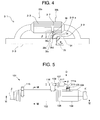
- Fig. 4 is a schematic view showing an exhaust heat recovery device 31 of Embodiment 2 according to the present invention.
- the heat recovery device 31 is disposed in an exhaust system of a vehicle, etc., having an internal combustion engine; an upstream side exhaust pipe (not shown) is connected to the upstream side of the device (left side in the drawing) and a downstream side exhaust pipe (not shown) is connected to the downstream side of the device (right side in the drawing).
- a heat exchanger 32 is connected to a cooling system of the internal combustion engine, not shown, by a medium outlet 32a and a medium inlet 32b and constructed such that it can perform heat exchange between the exhaust gas and a medium flowing through the heat exchanger 32.
- a bypass route 33 is provided to lead the exhaust gas to the downstream side exhaust pipe by bypassing the heat exchanger 32.
- a butterfly valve body 35 is provided on a valve shaft 36, being urged in the direction closing the bypass route 33 by an urging member 34 constituted by a spring, and the valve body 35 can rotate conjointly with the valve shaft 36 around the valve shaft 36.
- the valve body 35 is rotated against the urging force of the urging member 34 to open the bypass route 33.
- thermoelement 37 as the temperature-activated actuator is provided outside the heat exchanger 32 in such a manner that its heat receiving portion is brought into contact with the medium flowing through the heat exchanger 32.
- the thermoelement 37 causes a first arm 38a constituting an activating arm 38 to perform a translatory expanding motion in the ⁇ direction in Fig. 4, according to the heat expansion of the incorporated paraffin wax corresponding to temperature rise of the medium, and allows the first arm 38a of the activating arm 38 to perform a translatory contracting motion in the opposite direction to the above-mentioned direction by an incorporated return spring (not shown) when the paraffin wax is contracted.
- the free end of the first arm 38a is rotatably coupled to a second arm 38c by a rotational shaft 38b.
- crank 39 operatively coupling the activating arm 38 with the valve body 35 is provided for conjoint rotation with the valve shaft 36.
- the crank 39 is formed in a substantially triangular shape around the valve shaft 36 and is provided with an arc slot 39a around the valve shaft 36.
- a pin 38d provided at the free end of the second arm 38c of the activating arm 38 is loosely fitted in the arc slot 39a to be slidable within the range of the arc slot 39a for forming the floating mechanism.
- the exhaust gas rotates the valve body 35 in the ⁇ direction shown in Fig. 4.
- the crank 39 is rotated in the counterclockwise direction in Fig. 4 with the rotation of the valve body 35.
- the pin 38d of the activating arm 38 is slid in the slot 39a.
- the valve body 35 is rotated without being affected by the thermoelement 37 to open the bypass pipe 33.
- thermoelement 37 expands to move the first arm 38a of the activating arm 38 in the ⁇ direction.
- the pin 38d at the free end of the second arm 38c presses the lower end of the slot 39a in the drawing downwardly to rotate the crank 39 in the counterclockwise direction.
- the second arm 38c is rotated around the rotational shaft 38b to the right side in the drawing and rotates the crank 39 without any trouble.
- the valve body 35 is rotated in the opening direction by the rotation of the crank 39 in the counterclockwise direction to open the bypass pipe 33.
- Embodiment 2 can exhibit the same effect as Embodiment 1.
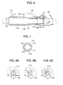
- Figs. 5 to 8 show Embodiment 3 according to the present invention, in which Fig. 5 is a front view showing an exhaust heat recovery device 101 of Embodiment 3, Fig. 6 is a vertical section view showing the exhaust heat recovery device 101 of Embodiment 3, taken along line VI - VI in Fig. 5, Fig. 7 is a cross-sectional view taken along line VII - VII in Fig. 5, and Figs. 8A to 8C are partially enlarged views showing operational states as seen in the D direction in Fig. 5.
- the exhaust heat recovery device 101 is disposed in an exhaust system of a vehicle, etc., having an internal combustion engine. As shown in Fig. 5, an upstream side exhaust pipe J is connected to the upstream side of the device (the left side in the drawing) and a downstream side exhaust pipe K is connected to the downstream side (the right side in the drawing) of the device.
- a first case 103 having a cylindrical shape is arranged on the upstream side of the exhaust heat recovery device 101.
- a heat exchange pipe 117 is provided inside the first case 103 substantially coaxially with the first case 103 and in a liquid-tight manner at both ends of the first case 103, and a medium flow part 114 is formed between the heat exchange pipe 117 and the first case 103.
- the cross section of the heat exchange pipe 117 of this embodiment in the direction orthogonal to its axial direction is formed in a wavy shape alternately forming four mountain portions 117a and four valley portions 117b in the circumference direction.
- the four valley portions (groove portions) 117b are helically formed in the axial direction.
- a medium outlet 115 connected to a cooling system of the internal combustion engine is provided in the first case 103.
- a medium inlet 116 is provided in a later-described element cover 108 disposed outside the first case 103.
- a medium flows through the medium flow part 114 and in the element cover 108.
- the first case 103, the medium flow part 114, the medium outlet 115, the medium inlet 116, the heat exchange pipe 117, and a space 118c constitute a heat exchanger.
- a second case 104 including two portions divided in the circumference direction is joined to the heat exchange pipe 117 so as to sandwich therebetween a retainer 106 having an opening, not shown.
- a bypass pipe 118 forming a bypass route therein is formed by two pipes including an upstream side bypass pipe 118a and a downstream side bypass pipe 118b connected by fitting one in another via a sliding member 119, the upstream end and the downstream end of the bypass pipe 118 are opened, and the bypass pipe 118 is retained inside the heat exchange pipe 117 substantially coaxially with the first case 103 by the upstream side end of the heat exchange pipe 117 and the retainer 106 provided on the downstream side of the heat exchange pipe 117.
- a plurality of small-diameter communication holes 126 are formed to be communicated with the space 118c formed between the bypass pipe 118 and the heat exchange pipe 117. Exhaust gas in the bypass pipe 118 can flow into the space 118c through the communication holes 126. Upon the flow of the exhaust gas, heat exchange is performed between the medium flowing through the medium flow part 114 and the exhaust gas.
- a butterfly valve body 122 opening and closing the bypass pipe 118 is provided integrally with a valve shaft 110 pivotally mounted to the bypass pipe 118, and is urged in the closing direction by an urging spring 125 urging the rotation of the valve shaft in the fixed direction.
- a cushioning member 121 suppressing any hitting noise of the valve body 122 onto the bypass pipe 118 is provided at the downstream end of the bypass pipe 118.
- the element cover 108 provided with a thermoelement 107 as the above-described temperature-activated actuator is disposed outside the first case 103.
- the medium circulating through the cooling portion of the internal combustion engine flows into the element cover 108 through the medium inlet 116.
- thermoelement 107 is arranged in such a manner that its heat receiving portion contacts the medium flowing through the element cover 108, and corresponding to the temperature of the medium, the thermoelement 107 causes the activating arm 112 to perform a translatory expanding motion in the ⁇ direction in Fig. 5, according to the heat expansion of the incorporated paraffin wax when the temperature is high, and allows the activating arm 112 to perform a translatory contracting motion in the opposite direction to the above-mentioned direction by a return spring (not shown) when the temperature is low and the paraffin wax contracts.
- a crank 111 is provided integrally with the valve shaft 110 for conjoint movement with the valve body 122, an engaging strip 111a formed on the crank 111 is arranged to face the activating arm 112, and the crank 111 opening and closing the valve body 122 by expanding and contracting the activating arm 112 is provided to be rotated integrally with the valve shaft 110.
- the activating arm 112 and the crank 111 are not joined to each other, can contact with each other, and can be spaced from each other, thereby forming the floating mechanism.
- Figs. 8A to 8C are partially enlarged views showing operational states as seen from the D direction in Fig. 5.
- Fig. 8A shows a case where the flow rate of the exhaust gas and the temperature of the medium are both equal to or lower than the predetermined value.
- the valve body 122 closes the bypass pipe 118 according to the urging force of the urging spring 125.
- the thermoelement 107 is also in the contracted state, and the activating arm 112 is spaced from the engaging strip 111a of the crank 111.
- Fig. 8B shows a case where the flow rate of the exhaust gas is equal to or higher than the predetermined value and the temperature of the medium is equal to or lower than the predetermined value.
- the thermoelement 107 is in the contracted state, but the flow of the exhaust gas pushes the valve body 122 to open the bypass pipe 118 against the urging force of the urging spring 125.
- the crank 111 rotated integrally with the valve body 122 is provided so that it can be spaced from the activating arm 112 so that it can be spaced from the activating arm 112, the valve body 122 is rotated in the opening direction to open the bypass pipe 18 even if the thermoelement 107 does not operates and the activating arm 112 does not expand.
- Fig. 8C shows a case where the temperature of the medium is equal to or higher than the predetermined value and the flow rate of the exhaust gas is equal to or lower than the predetermined value.
- the thermoelement 107 expands so that the activating arm 112 is brought into contact with the engaging strip 111a of the crank 111 to push it to thereby rotate the crank 111.
- the valve body 122 rotated integrally with the crank 111 is rotated in the opening direction to open the bypass pipe 18.
- Embodiment 3 can exhibit the same effect as Embodiment 1.
- the urging member of the valve body may serve as the urging member (return spring) included in the thermoelement.
- a bimetal or a shape-memory alloy is used for the temperature-activated actuator.
- the valve body may be rotated by shape change of these.
- a heat exchanger, a valve body, an urging member, a crank mechanism, and a floating mechanism of conventionally known constitution can be optionally employed.
- a sound absorbing material may be provided in the bypass route and the heat exchange route to provide a noise suppressing function to the heat recovery device.
- the present invention is not limited to a heat recovery device (heat collector, oil warmer, and the like) in a narrow sense mainly for heat recovery of a medium, and includes a heat exchanger (exhaust cooler, EGR cooler, and the like) mainly for cooling exhaust gas as a heat recovery device.
- the present invention is not limited for being applied to an internal combustion engine of a vehicle and can be applied to exhaust systems of all exhaust gas generators such as a general-purpose engine and a stationary type combustor.
Landscapes
- Engineering & Computer Science (AREA)
- Chemical & Material Sciences (AREA)
- Combustion & Propulsion (AREA)
- Mechanical Engineering (AREA)
- General Engineering & Computer Science (AREA)
- Exhaust Silencers (AREA)
Abstract
Description
- The present invention relates to an exhaust heat recovery device provided in an exhaust system of a vehicle equipped with an internal combustion engine and recovering exhaust heat to use it for warm-up etc.
- There has been known such an exhaust heat recovery device which opens and closes a valve body of an exhaust system according to the driving state of an internal combustion engine and the temperature of a medium (cooling water) and can perform switching control of the passage of exhaust gas between a heat exchanger in the exhaust system and a bypass route through which the exhaust gas bypasses the heat exchanger. By controlling in this manner, an exhaust heat recovery device described in
Patent Document 1, for example, is intended to eliminate the defect of the driving performance in the cold state of a vehicle.
Patent Document 1:JP-U-63-160315 - The exhaust heat recovery device described in the above-mentioned
Patent Document 1 requires driving means such as a motor and a power driving actuator for driving a valve body used for switching control in the valve, control means such as a computer for controlling the same, and detecting means for detecting the rotational speed of the internal combustion engine and the temperature of the medium. Wiring and piping are required for connecting them and a dedicated design is required for each vehicle. This cannot be an advantageous method in cost. - To solve the above problems, the invention according to
claim 1 is an exhaust heat recovery device provided in an exhaust system of an internal combustion engine and comprising a heat exchanger for performing heat exchange between exhaust gas and a medium, a bypass route through which the exhaust gas bypasses the heat exchanger, and a valve body for opening and closing the bypass route, wherein the exhaust heat recovery device comprises the valve body that operates to open the bypass route from a closed state against urging force of an urging member when the flow rate of the exhaust gas is equal to or higher than a predetermined value, and a temperature-activated actuator that causes the valve body to open when the temperature of the medium is equal to or higher than a predetermined value, whereby the valve body operates to open when at least one of the flow rate of the exhaust gas and the temperature of the medium is equal to or higher than the corresponding predetermined value. - The invention according to
claim 2, in the invention according toclaim 1, is an exhaust heat recovery device further including a crank mechanism that causes the valve body to open by an expanding movement of the temperature-activated actuator which expands and contracts according to the temperature of the medium, and a floating mechanism that couples the contracting movement of the temperature-activated actuator and the closing movement of the valve body in a floating state. - The invention according to
claim 3, in the invention according toclaim - According to the present invention, when the flow rate of the exhaust gas is increased to be equal to or higher than the predetermined value, the valve body is opened so as to open the bypass route regardless of the temperature of the medium and the exhaust gas thus flows through the bypass route, bypassing the heat exchanger on the exhaust system, and accordingly, the flow resistance of the exhaust gas in the exhaust system can be reduced. It is therefore possible to eliminate the disadvantage of the driving performance when the vehicle is started in the insufficient warmed state. Further, also in the state where the flow rate of the exhaust gas is low and the bypass route is closed by the valve body, if the temperature of the medium is equal to or higher than the predetermined value, the temperature-activated actuator causes the valve body to open so as to open the bypass route, and the exhaust gas then bypasses the heat exchanger so as to flow through the bypass route, and accordingly, it is possible to suppress overheat of the medium flowing through the heat exchanger. Therefore, the overload on a cooling system of a vehicle concerned in a traffic jam can be prevented.
- Also, the control of this exhaust heat recovery device is completed in the exhaust heat recovery device, and none of wiring, piping, detecting means, control means and power supply are required, thus, the present invention is excellent in mounting ability, economy effect, and reliability.
- Best mode for carrying out the present invention will be described on the basis of embodiments shown in Figs. 1 to 8C.
- Figs. 1 to 3
show Embodiment 1 according to the present invention, in which Fig. 1 is a front view showing an exhaustheat recovery device 1 ofEmbodiment 1, Fig. 2 is a vertical section view of the exhaustheat recovery device 1 in Fig. 1, and Fig. 3 is a cross-sectional view taken along line III - III in Fig. 1. - The exhaust
heat recovery device 1 is disposed in an exhaust system of a vehicle, etc., having an internal combustion engine; an upstream side exhaust pipe J is connected to the upstream side of the device 1 (on a left side in the drawing) and a downstream side exhaust pipe K is connected to the downstream side of the device 1 (on a right side in the drawing), as shown in Fig. 1. A funnel-shaped cone 2 and one end of afirst case 3 having a cylindrical shape, and the other end of thefirst case 3 and asecond case 4 having a tubular shape are joined to each other so as tosandwich retainers - A
cover pipe 13 is provided inside thefirst case 3 substantially coaxially with thefirst case 3 and through both theretainers first case 3, thecover pipe 13, and both theretainers medium flow part 14. Amedium inlet 16 and amedium outlet 15 which are connected to a cooling system of the internal combustion engine are provided in thefirst case 3 so that a medium flows through themedium flow part 14.Heat exchange pipes 17 having helical grooves formed therein are arranged in themedium flow part 14, extending through both theretainers heat exchange pipes 17 are disposed so as to surround the outer circumference of thecover pipe 13, as shown in Fig. 3, and the heat exchange is performed between the medium flowing through themedium flow part 14 and the exhaust gas when exhaust gas flows through theheat exchange pipes 17. InEmbodiment 1, thefirst case 3, theretainers cover pipe 13, themedium flow part 14, themedium inlet 16, themedium outlet 15, and theheat exchange pipes 17 constitute a heat exchanger. - Outside the
first case 3, there are provided athermoelement 7 as a temperature-activated actuator, and anelement cover 8 covering the same. Theelement cover 8 is constructed such that the medium flowing through themedium flow part 14 can flow in the inside of theelement cover 8 so that thethermoelement 7 and the medium can contact with each other. Thethermoelement 7 causes an activatingarm 12 to perform a translatory expanding motion in the β direction, according to the heat expansion of the incorporated paraffin wax corresponding to a temperature rise of the flowing medium, and allows the activatingarm 12 to perform a translatory contracting motion in the opposite direction to the above-mentioned direction by areturn spring 9 disposed in thethermoelement 7 when the temperature of the medium is lowered and the paraffin wax contracts. The activatingarm 12 has at its end an axially extendingslot 26 and arod 25 having apin 27 engaging with theslot 26 can slide axially within the range of theslot 26, so as to form a floating mechanism. - A
bypass pipe 18 forming a bypass route is disposed inside thecover pipe 13 substantially coaxially with thecover pipe 13. Thebypass pipe 18 is formed by a cylindrical pipe having upstream and downstream open ends, joined to the downstream end of thecover pipe 13, and held onto the upstream end of thecover pipe 13 via a slidingmember 19. This can absorb a heat expansion difference between thecover pipe 13 and thebypass pipe 18 caused when the exhaust gas flows through thebypass pipe 18, thereby improving durability. - As shown in Fig. 2, a
valve seat 20 and acushioning member 21 suppressing any hitting noise are provided at the downstream end of thebypass pipe 18.
Abutterfly valve body 22 which contacts with thevalve seat 20 and can open and close thebypass pipe 18 is rotatably provided on avalve shaft 10 disposed at a periphery near the end of thebypass pipe 18, and is urged in the closing direction of thebypass pipe 18 by an urging spring, not shown. When the flow rate of the exhaust gas flowing through thebypass pipe 18 is equal to or lower than a predetermined value, thevalve body 22 closes the downstream end of thebypass pipe 18 by the urging force of the urging spring. The valve system opening and closing according to the flow rate of the exhaust gas is known in the exhaust devices as a variable valve. - One end of the
valve shaft 10 protrudes outside thesecond case 4, one end of acrank 11 is integrally journaled to the protruding end of thevalve shaft 10, and therod 25 of the above-described floating mechanism is journaled to the other end of thecrank 11 via apivot 24. Thevalve body 22 is rotated via the crank mechanism by the expansion and contraction of thethermoelement 7. - The operation of the thus-constituted exhaust
heat recovery device 1 ofEmbodiment 1 will be described.
When the flow rate of the exhaust gas and the temperature of the medium are equal to or lower than the respectively predetermined values, thevalve body 22 closes thebypass pipe 18 by the urging force of the urging spring, not shown. The exhaust gas forcibly flows through in theheat exchange pipes 17 to be heat-exchanged between the exhaust gas and the medium flowing through themedium flow part 14. - When the flow rate of the exhaust gas is equal to or higher than the predetermined value, even if the temperature of the medium is equal to or lower than the predetermined value, the exhaust gas rotates the
valve body 22 in the α direction shown in Fig. 2. Therod 25 is moved in the β direction shown in Fig. 1, accompanying the rotation of thecrank 11 provided integrally with thevalve body 22, but thevalve body 22 can be rotated without being affected by thethermoelement 7 to open thebypass pipe 18 since therod 25 is coupled to the activatingarm 12 in the floating manner. - When the temperature of the medium is equal to or higher than the predetermined value, even if the flow rate of the exhaust gas is equal to or lower than the predetermined value, the
thermoelement 7 expands to move the activatingarm 12 in the β direction and the left end of theslot 26 in the drawing is engaged with thepin 27 to move therod 25 in the β direction.
Along with it, the rotation of thecrank 11 about thevalve shaft 10 causes thevalve body 22 integral therewith to rotate in the α direction and in the opening direction to open thebypass pipe 18. - In
Embodiment 1, when the flow rate of the exhaust gas is increased to be equal to or higher than the predetermined value, thebypass pipe 18 is opened regardless of the temperature of the medium and the exhaust gas then bypasses theheat exchange pipes 17 to flow through thebypass pipe 18. Thus, the flow resistance of the exhaust gas can be reduced, and accordingly, it is possible to eliminate the disadvantage of the driving performance when a vehicle is started in the state that warm-up is insufficient. On the other hand, even in the state that the flow rate of the exhaust gas is low and thebypass pipe 18 is closed by thevalve body 22, when the temperature of the medium is equal to or higher than the predetermined value, thethermoelement 7 as the temperature-activated actuator causes thevalve body 22 to open, and the exhaust gas bypasses theheat exchange pipes 17 to flow through thebypass pipe 18, whereby the overheat of the medium can be prevented. Therefore, concerns of the overload on a cooling system of a vehicle equipped with an internal combustion engine in a traffic jam can be prevented. - Fig. 4 is a schematic view showing an exhaust
heat recovery device 31 ofEmbodiment 2 according to the present invention. - The
heat recovery device 31 is disposed in an exhaust system of a vehicle, etc., having an internal combustion engine; an upstream side exhaust pipe (not shown) is connected to the upstream side of the device (left side in the drawing) and a downstream side exhaust pipe (not shown) is connected to the downstream side of the device (right side in the drawing). Aheat exchanger 32 is connected to a cooling system of the internal combustion engine, not shown, by amedium outlet 32a and amedium inlet 32b and constructed such that it can perform heat exchange between the exhaust gas and a medium flowing through theheat exchanger 32. Abypass route 33 is provided to lead the exhaust gas to the downstream side exhaust pipe by bypassing theheat exchanger 32. On the way of thebypass route 33, abutterfly valve body 35 is provided on avalve shaft 36, being urged in the direction closing thebypass route 33 by anurging member 34 constituted by a spring, and thevalve body 35 can rotate conjointly with thevalve shaft 36 around thevalve shaft 36. When the flow rate of the exhaust gas is equal to or higher than the predetermined value, thevalve body 35 is rotated against the urging force of theurging member 34 to open thebypass route 33. - A
thermoelement 37 as the temperature-activated actuator is provided outside theheat exchanger 32 in such a manner that its heat receiving portion is brought into contact with the medium flowing through theheat exchanger 32. Thethermoelement 37 causes afirst arm 38a constituting an activatingarm 38 to perform a translatory expanding motion in the β direction in Fig. 4, according to the heat expansion of the incorporated paraffin wax corresponding to temperature rise of the medium, and allows thefirst arm 38a of the activatingarm 38 to perform a translatory contracting motion in the opposite direction to the above-mentioned direction by an incorporated return spring (not shown) when the paraffin wax is contracted. The free end of thefirst arm 38a is rotatably coupled to asecond arm 38c by arotational shaft 38b. In addition, acrank 39 operatively coupling the activatingarm 38 with thevalve body 35 is provided for conjoint rotation with thevalve shaft 36. In addition, as shown in Fig. 4, thecrank 39 is formed in a substantially triangular shape around thevalve shaft 36 and is provided with an arc slot 39a around thevalve shaft 36. Apin 38d provided at the free end of thesecond arm 38c of the activatingarm 38 is loosely fitted in the arc slot 39a to be slidable within the range of the arc slot 39a for forming the floating mechanism. - The operation of the thus-constituted exhaust
heat recovery device 31 ofEmbodiment 2 will be described.
When the flow rate of the exhaust gas and the temperature of the medium are both equal to or lower than the respectively predetermined values, thevalve body 35 closes thebypass pipe 33 by the urging force of the urgingmember 34. The exhaust gas forcefully flows through theheat exchanger 32 to be heat-exchanged between the exhaust gas and the medium. - When the flow rate of the exhaust gas is equal to or higher than the predetermined value, even if the temperature of the medium is equal to or lower than the predetermined value, the exhaust gas rotates the
valve body 35 in the α direction shown in Fig. 4. Thecrank 39 is rotated in the counterclockwise direction in Fig. 4 with the rotation of thevalve body 35. Thepin 38d of the activatingarm 38 is slid in the slot 39a. Thevalve body 35 is rotated without being affected by thethermoelement 37 to open thebypass pipe 33. - Even if the flow rate of the exhaust gas is equal to or lower than the predetermined value, when the temperature of the medium is equal to or higher than the predetermined value, the
thermoelement 37 expands to move thefirst arm 38a of the activatingarm 38 in the β direction. Thepin 38d at the free end of thesecond arm 38c presses the lower end of the slot 39a in the drawing downwardly to rotate thecrank 39 in the counterclockwise direction. At the rotation, thesecond arm 38c is rotated around therotational shaft 38b to the right side in the drawing and rotates thecrank 39 without any trouble. Thevalve body 35 is rotated in the opening direction by the rotation of thecrank 39 in the counterclockwise direction to open thebypass pipe 33. -
Embodiment 2 can exhibit the same effect asEmbodiment 1. - Figs. 5 to 8
show Embodiment 3 according to the present invention, in which Fig. 5 is a front view showing an exhaustheat recovery device 101 ofEmbodiment 3, Fig. 6 is a vertical section view showing the exhaustheat recovery device 101 ofEmbodiment 3, taken along line VI - VI in Fig. 5, Fig. 7 is a cross-sectional view taken along line VII - VII in Fig. 5, and Figs. 8A to 8C are partially enlarged views showing operational states as seen in the D direction in Fig. 5. - The exhaust
heat recovery device 101 is disposed in an exhaust system of a vehicle, etc., having an internal combustion engine. As shown in Fig. 5, an upstream side exhaust pipe J is connected to the upstream side of the device (the left side in the drawing) and a downstream side exhaust pipe K is connected to the downstream side (the right side in the drawing) of the device. - A
first case 103 having a cylindrical shape is arranged on the upstream side of the exhaustheat recovery device 101. As shown in Fig. 6, aheat exchange pipe 117 is provided inside thefirst case 103 substantially coaxially with thefirst case 103 and in a liquid-tight manner at both ends of thefirst case 103, and amedium flow part 114 is formed between theheat exchange pipe 117 and thefirst case 103. As shown in Fig. 7, the cross section of theheat exchange pipe 117 of this embodiment in the direction orthogonal to its axial direction is formed in a wavy shape alternately forming fourmountain portions 117a and fourvalley portions 117b in the circumference direction. The four valley portions (groove portions) 117b are helically formed in the axial direction. - A
medium outlet 115 connected to a cooling system of the internal combustion engine is provided in thefirst case 103. Amedium inlet 116 is provided in a later-describedelement cover 108 disposed outside thefirst case 103. A medium flows through themedium flow part 114 and in theelement cover 108. InEmbodiment 3, thefirst case 103, themedium flow part 114, themedium outlet 115, themedium inlet 116, theheat exchange pipe 117, and aspace 118c constitute a heat exchanger. - On the downstream side of the
heat exchange pipe 117, asecond case 104 including two portions divided in the circumference direction is joined to theheat exchange pipe 117 so as to sandwich therebetween aretainer 106 having an opening, not shown. - A
bypass pipe 118 forming a bypass route therein is formed by two pipes including an upstreamside bypass pipe 118a and a downstream side bypass pipe 118b connected by fitting one in another via a slidingmember 119, the upstream end and the downstream end of thebypass pipe 118 are opened, and thebypass pipe 118 is retained inside theheat exchange pipe 117 substantially coaxially with thefirst case 103 by the upstream side end of theheat exchange pipe 117 and theretainer 106 provided on the downstream side of theheat exchange pipe 117. - Near the upstream end of the
bypass pipe 118, a plurality of small-diameter communication holes 126 are formed to be communicated with thespace 118c formed between thebypass pipe 118 and theheat exchange pipe 117. Exhaust gas in thebypass pipe 118 can flow into thespace 118c through the communication holes 126. Upon the flow of the exhaust gas, heat exchange is performed between the medium flowing through themedium flow part 114 and the exhaust gas. - In the downstream portion of the
bypass pipe 118, abutterfly valve body 122 opening and closing thebypass pipe 118 is provided integrally with avalve shaft 110 pivotally mounted to thebypass pipe 118, and is urged in the closing direction by an urgingspring 125 urging the rotation of the valve shaft in the fixed direction. A cushioningmember 121 suppressing any hitting noise of thevalve body 122 onto thebypass pipe 118 is provided at the downstream end of thebypass pipe 118. - With this constitution, when the flow rate of the exhaust gas flowing through the
bypass pipe 118 is equal to or lower than the predetermined value, thevalve body 122 is urged by the urgingspring 125 to close the downstream end of thebypass pipe 118. When the flow rate of the exhaust gas is equal to or higher than the predetermined value, thevalve body 122 is opened against the urging force of the urgingspring 125. - As shown in Fig. 5, the
element cover 108 provided with athermoelement 107 as the above-described temperature-activated actuator is disposed outside thefirst case 103. The medium circulating through the cooling portion of the internal combustion engine flows into theelement cover 108 through themedium inlet 116. - The
thermoelement 107 is arranged in such a manner that its heat receiving portion contacts the medium flowing through theelement cover 108, and corresponding to the temperature of the medium, thethermoelement 107 causes the activatingarm 112 to perform a translatory expanding motion in the β direction in Fig. 5, according to the heat expansion of the incorporated paraffin wax when the temperature is high, and allows the activatingarm 112 to perform a translatory contracting motion in the opposite direction to the above-mentioned direction by a return spring (not shown) when the temperature is low and the paraffin wax contracts. - A
crank 111 is provided integrally with thevalve shaft 110 for conjoint movement with thevalve body 122, an engagingstrip 111a formed on thecrank 111 is arranged to face the activatingarm 112, and thecrank 111 opening and closing thevalve body 122 by expanding and contracting the activatingarm 112 is provided to be rotated integrally with thevalve shaft 110.
The activatingarm 112 and thecrank 111 are not joined to each other, can contact with each other, and can be spaced from each other, thereby forming the floating mechanism. - The operation of
Embodiment 3 will be described.
Figs. 8A to 8C are partially enlarged views showing operational states as seen from the D direction in Fig. 5. - Fig. 8A shows a case where the flow rate of the exhaust gas and the temperature of the medium are both equal to or lower than the predetermined value.
In this case, thevalve body 122 closes thebypass pipe 118 according to the urging force of the urgingspring 125. Thethermoelement 107 is also in the contracted state, and the activatingarm 112 is spaced from the engagingstrip 111a of thecrank 111. - Fig. 8B shows a case where the flow rate of the exhaust gas is equal to or higher than the predetermined value and the temperature of the medium is equal to or lower than the predetermined value.
In this case, thethermoelement 107 is in the contracted state, but the flow of the exhaust gas pushes thevalve body 122 to open thebypass pipe 118 against the urging force of the urgingspring 125. At this time, since thecrank 111 rotated integrally with thevalve body 122 is provided so that it can be spaced from the activatingarm 112, thevalve body 122 is rotated in the opening direction to open thebypass pipe 18 even if thethermoelement 107 does not operates and the activatingarm 112 does not expand. - Fig. 8C shows a case where the temperature of the medium is equal to or higher than the predetermined value and the flow rate of the exhaust gas is equal to or lower than the predetermined value.
In this case, thethermoelement 107 expands so that the activatingarm 112 is brought into contact with the engagingstrip 111a of thecrank 111 to push it to thereby rotate thecrank 111. Thus, thevalve body 122 rotated integrally with thecrank 111 is rotated in the opening direction to open thebypass pipe 18. -
Embodiment 3 can exhibit the same effect asEmbodiment 1. - The embodiments according to the present invention are described above, but the present invention is not limited to the above embodiments, and design changes in the scope without departing from the purport of the present invention are included in the present invention.
- For example, the urging member of the valve body may serve as the urging member (return spring) included in the thermoelement.
A bimetal or a shape-memory alloy is used for the temperature-activated actuator. The valve body may be rotated by shape change of these.
A heat exchanger, a valve body, an urging member, a crank mechanism, and a floating mechanism of conventionally known constitution can be optionally employed.
A sound absorbing material may be provided in the bypass route and the heat exchange route to provide a noise suppressing function to the heat recovery device. - The present invention is not limited to a heat recovery device (heat collector, oil warmer, and the like) in a narrow sense mainly for heat recovery of a medium, and includes a heat exchanger (exhaust cooler, EGR cooler, and the like) mainly for cooling exhaust gas as a heat recovery device. The present invention is not limited for being applied to an internal combustion engine of a vehicle and can be applied to exhaust systems of all exhaust gas generators such as a general-purpose engine and a stationary type combustor.
-
- Fig. 1 is a front view showing an exhaust heat recovery device of
Embodiment 1 according to the present invention; - Fig. 2 is a vertical section view of the exhaust heat recovery device in Fig. 1;
- Fig. 3 is a cross-sectional view taken along line III - III in Fig. 1;
- Fig. 4 is a schematic view showing an exhaust heat recovery device of
Embodiment 2 according to the present invention; - Fig. 5 is a front view showing an exhaust heat recovery device of
Embodiment 3 according to the present invention; - Fig. 6 is a vertical section view of the exhaust heat recovery device taken along line VI - VI in Fig. 5;
- Fig. 7 is a cross-sectional view taken along line VII - VII in Fig. 5;
- Fig. 8A is a partially enlarged view showing an operated state as seen in the D direction in Fig. 5;
- Fig. 8B is a partially enlarged view showing another operated state as seen in the D direction in Fig. 5; and
- Fig. 8C is a partially enlarged view showing a further operated state as seen in the D direction in Fig. 5.
Claims (3)
- An exhaust heat recovery device provided in an exhaust system of an internal combustion engine or the like and comprising a heat exchanger for performing heat exchange between exhaust gas and a medium, a bypass route through which the exhaust gas bypasses the heat exchanger, and a valve body for opening and closing the bypass route,
wherein said exhaust heat recovery device further comprises a valve body that operates to open said bypass route from a closed state against urging force of an urging member when a flow rate of the exhaust gas is equal to or higher than a predetermined value, and a temperature-activated actuator that causes said valve body to open when the temperature of said medium is equal to or higher than a predetermined value, whereby said valve body operates to open when at least one of the flow rate of the exhaust gas and the temperature of the medium is equal to or higher than the corresponding predetermined value. - The exhaust heat recovery device according to claim 1, further comprising a crank mechanism that causes said valve body to open by an expanding movement of said temperature-activated actuator which expands and contracts according to the temperature of said medium, and a floating mechanism that couples the contracting movement of said temperature-activated actuator and the closing movement of said valve body in an floating state.
- The exhaust heat recovery device according to claim 1 or 2, wherein said temperature-activated actuator is a thermoelement which expands and contracts by an incorporated wax.
Applications Claiming Priority (2)
| Application Number | Priority Date | Filing Date | Title |
|---|---|---|---|
| JP2005087052 | 2005-02-23 | ||
| PCT/JP2006/303135 WO2006090725A1 (en) | 2005-02-23 | 2006-02-22 | Exhaust heat recovery device |
Publications (3)
| Publication Number | Publication Date |
|---|---|
| EP1852585A1 true EP1852585A1 (en) | 2007-11-07 |
| EP1852585A4 EP1852585A4 (en) | 2010-11-17 |
| EP1852585B1 EP1852585B1 (en) | 2012-04-11 |
Family
ID=36927363
Family Applications (1)
| Application Number | Title | Priority Date | Filing Date |
|---|---|---|---|
| EP06714275A Ceased EP1852585B1 (en) | 2005-02-23 | 2006-02-22 | Exhaust heat recovery device |
Country Status (4)
| Country | Link |
|---|---|
| US (1) | US20090049832A1 (en) |
| EP (1) | EP1852585B1 (en) |
| JP (1) | JPWO2006090725A1 (en) |
| WO (1) | WO2006090725A1 (en) |
Cited By (10)
| Publication number | Priority date | Publication date | Assignee | Title |
|---|---|---|---|---|
| FR2933734A1 (en) * | 2008-07-10 | 2010-01-15 | Faurecia Sys Echappement | Exhaust line for motor vehicle, has orientation units orienting part of exhaust gas through exchanger and part of gas towards part of by-pass duct by by-passing exchanger if flow of gas in upstream duct is higher than preset value |
| DE102010011472A1 (en) | 2010-03-15 | 2011-09-15 | Bayerische Motoren Werke Aktiengesellschaft | Device for exhaust gas heat utilization in internal combustion engine of motor car, has extension substance actuator provided for temperature-dependent operation of valve flap that is movable between closing and open positions |
| FR2974146A1 (en) * | 2011-04-15 | 2012-10-19 | Faurecia Sys Echappement | Element for controlling exhaust line valves in heat engine of car, has overtravel spring absorbing overtravel of piston beyond its active position when specific temperature exceeds preset upper limit, and body attached to obturation unit |
| EP2716886A1 (en) * | 2012-10-08 | 2014-04-09 | Rolls-Royce plc | An exhaust arrangement |
| EP3109428A1 (en) * | 2015-06-24 | 2016-12-28 | Toyota Jidosha Kabushiki Kaisha | Exhaust heat recovery structure |
| DE102016103458A1 (en) * | 2016-02-26 | 2017-08-31 | Hanon Systems | Wrap heat exchanger |
| FR3057611A1 (en) * | 2016-10-19 | 2018-04-20 | Faurecia Systemes D'echappement | ACTUATOR FOR A VALVE OF A DEVICE FOR RECOVERING HEAT FROM EXHAUST, IN PARTICULAR FROM A MOTOR VEHICLE |
| WO2018103898A1 (en) * | 2016-12-09 | 2018-06-14 | Faurecia Systemes D'echappement | Exhaust heat recuperation device, with improved sealing |
| WO2018224302A1 (en) * | 2017-06-08 | 2018-12-13 | Volkswagen Aktiengesellschaft | Device for recovering heat from an exhaust gas |
| RU2735768C1 (en) * | 2017-06-08 | 2020-11-06 | Фольксваген Акциенгезельшафт | Heat recuperation device |
Families Citing this family (38)
| Publication number | Priority date | Publication date | Assignee | Title |
|---|---|---|---|---|
| FR2904374B1 (en) * | 2006-07-25 | 2012-10-26 | Valeo Sys Controle Moteur Sas | VALVE WITH DERIVED CHANNEL INCORPORATING A HEATING MEMBER AND INTAKE CIRCUIT WITH AIR PREHEATING FOR THERMAL ENGINE |
| JP2008101481A (en) * | 2006-10-17 | 2008-05-01 | Toyota Motor Corp | Exhaust system structure |
| GB0813938D0 (en) * | 2008-07-30 | 2008-09-03 | Heat Recovery Solutions Ltd | Heat exchanger |
| DE102008051268A1 (en) * | 2008-10-10 | 2010-04-15 | Mahle International Gmbh | cooling device |
| US8443593B2 (en) * | 2008-12-12 | 2013-05-21 | Westcast Industries, Inc. | Liquid-cooled exhaust valve assembly |
| JP2010144566A (en) * | 2008-12-17 | 2010-07-01 | Calsonic Kansei Corp | Switching valve structure |
| JP5120319B2 (en) * | 2009-04-03 | 2013-01-16 | 株式会社デンソー | Engine waste heat control device |
| DE102010005803A1 (en) * | 2010-01-27 | 2011-07-28 | Audi Ag, 85057 | Car with an exhaust system |
| US8424296B2 (en) * | 2010-06-11 | 2013-04-23 | Dana Canada Corporation | Annular heat exchanger |
| US9664087B2 (en) | 2010-07-22 | 2017-05-30 | Wescast Industries, Inc. | Exhaust heat recovery system with bypass |
| JP5581246B2 (en) * | 2011-03-03 | 2014-08-27 | 株式会社ユタカ技研 | Waste heat recovery device |
| JP5581247B2 (en) * | 2011-03-03 | 2014-08-27 | 株式会社ユタカ技研 | Waste heat recovery device |
| CA2769913C (en) | 2011-03-03 | 2013-09-24 | Toru Hisanaga | Exhaust heat recovery device |
| DE102011016808A1 (en) | 2011-04-13 | 2012-10-18 | Emitec Gesellschaft Für Emissionstechnologie Mbh | Device with a heat exchanger for a thermoelectric generator of a motor vehicle |
| DE102011016886A1 (en) | 2011-04-13 | 2012-10-18 | Emitec Gesellschaft Für Emissionstechnologie Mbh | Device with a heat exchanger for a thermoelectric generator of a motor vehicle |
| DE102011103109A1 (en) * | 2011-05-25 | 2012-11-29 | Benteler Automobiltechnik Gmbh | Exhaust system with heat storage |
| KR20140075710A (en) | 2011-09-09 | 2014-06-19 | 다나 캐나다 코포레이션 | Exhaust gas heat recovery device |
| US9739243B2 (en) * | 2012-02-10 | 2017-08-22 | Ford Gloabl Technologies, LLC | Methods and systems for fuel vapor control |
| US9989322B2 (en) | 2013-03-01 | 2018-06-05 | Dana Canada Corporation | Heat recovery device with improved lightweight flow coupling chamber and insertable valve |
| US9127626B2 (en) | 2013-04-24 | 2015-09-08 | Ford Global Technologies, Llc | Methods and systems for turbocharger control |
| JP6086837B2 (en) * | 2013-08-06 | 2017-03-01 | 株式会社三五 | Exhaust heat recovery device |
| KR101499221B1 (en) * | 2013-11-14 | 2015-03-05 | 현대자동차주식회사 | Apparatus for exhaust heat recovery with embedded valve actuator |
| CA2933269A1 (en) * | 2013-12-16 | 2015-06-25 | Dana Canada Corporation | Heat recovery device with standoff heat exchanger mount |
| KR101610099B1 (en) * | 2014-04-30 | 2016-04-08 | 현대자동차 주식회사 | Heat exchanger of can type |
| US10006369B2 (en) * | 2014-06-30 | 2018-06-26 | General Electric Company | Method and system for radial tubular duct heat exchangers |
| JP6538344B2 (en) * | 2014-12-16 | 2019-07-03 | フタバ産業株式会社 | Exhaust heat recovery system |
| JP6455159B2 (en) * | 2015-01-14 | 2019-01-23 | アイシン精機株式会社 | Vehicle exhaust heat recovery device |
| JP6761424B2 (en) * | 2015-10-23 | 2020-09-23 | 日本碍子株式会社 | Exhaust heat recovery device |
| US9689295B1 (en) | 2016-01-29 | 2017-06-27 | Ford Global Technologies, Llc | Method and system for exhaust gas heat recovery |
| US9957871B2 (en) | 2016-01-29 | 2018-05-01 | Ford Global Technologies, Llc | Exhaust heat recovery and hydrocarbon trapping |
| US9845750B2 (en) | 2016-01-29 | 2017-12-19 | Ford Global Technologies, Llc | Method and system for exhaust gas heat recovery |
| US10371088B2 (en) | 2016-02-15 | 2019-08-06 | Ford Global Technologies, Llc | Heat exchanger for a rankine cycle in a vehicle muffler |
| DE102017205434A1 (en) * | 2016-04-11 | 2017-10-26 | Toyota Jidosha Kabushiki Kaisha | Exhaust heat recovery device |
| DE102017210276A1 (en) * | 2016-11-29 | 2018-05-30 | Mahle International Gmbh | Heat exchanger, in particular exhaust gas heat exchanger, for a motor vehicle |
| DE102017209725A1 (en) * | 2017-06-08 | 2018-12-13 | Volkswagen Aktiengesellschaft | Device for heat recovery from a heating fluid |
| DE102017209727A1 (en) * | 2017-06-08 | 2018-12-13 | Volkswagen Aktiengesellschaft | Device for heat recovery |
| CN111512111A (en) * | 2018-01-05 | 2020-08-07 | 日本碍子株式会社 | Heat exchange member, heat exchanger, and heat exchanger with purification mechanism |
| JP7046039B2 (en) * | 2019-09-12 | 2022-04-01 | 日本碍子株式会社 | Heat exchanger |
Family Cites Families (9)
| Publication number | Priority date | Publication date | Assignee | Title |
|---|---|---|---|---|
| US53771A (en) * | 1866-04-10 | Improved leather-splitting machine | ||
| US3615848A (en) * | 1969-02-27 | 1971-10-26 | Isotopes Inc | Thermal control for fuel cell module |
| JPS63160315U (en) | 1987-04-09 | 1988-10-20 | ||
| JPH0610147Y2 (en) * | 1987-06-12 | 1994-03-16 | 本田技研工業株式会社 | Exhaust pipe structure |
| JPH04353256A (en) * | 1991-05-31 | 1992-12-08 | Suzuki Motor Corp | Evaporated fuel adsorbing equipment |
| DE19725674A1 (en) * | 1997-06-18 | 1998-12-24 | Bayerische Motoren Werke Ag | Method for operating a heat exchanger in the exhaust gas stream of an internal combustion engine for motor vehicles |
| DE10253469A1 (en) * | 2002-11-16 | 2004-05-27 | Daimlerchrysler Ag | Thermostatic valve for a combustion engine cooling system has electrically heated wax cartridge element to control valve operation |
| JP4157752B2 (en) * | 2002-11-19 | 2008-10-01 | カルソニックカンセイ株式会社 | Engine exhaust heat recovery device |
| JP2004211660A (en) * | 2003-01-08 | 2004-07-29 | Toyota Motor Corp | Exhaust system |
-
2006
- 2006-02-22 EP EP06714275A patent/EP1852585B1/en not_active Ceased
- 2006-02-22 US US11/816,792 patent/US20090049832A1/en not_active Abandoned
- 2006-02-22 JP JP2007504740A patent/JPWO2006090725A1/en active Pending
- 2006-02-22 WO PCT/JP2006/303135 patent/WO2006090725A1/en not_active Ceased
Cited By (19)
| Publication number | Priority date | Publication date | Assignee | Title |
|---|---|---|---|---|
| FR2933734A1 (en) * | 2008-07-10 | 2010-01-15 | Faurecia Sys Echappement | Exhaust line for motor vehicle, has orientation units orienting part of exhaust gas through exchanger and part of gas towards part of by-pass duct by by-passing exchanger if flow of gas in upstream duct is higher than preset value |
| DE102010011472A1 (en) | 2010-03-15 | 2011-09-15 | Bayerische Motoren Werke Aktiengesellschaft | Device for exhaust gas heat utilization in internal combustion engine of motor car, has extension substance actuator provided for temperature-dependent operation of valve flap that is movable between closing and open positions |
| US20120060484A1 (en) * | 2010-03-15 | 2012-03-15 | Bayerische Motoren Werke Ag | Device for exhaust gas heat utilization |
| US8800263B2 (en) * | 2010-03-15 | 2014-08-12 | Faurecia Emissions Control Technologies, Germany Gmbh | Device for exhaust gas heat utilization |
| FR2974146A1 (en) * | 2011-04-15 | 2012-10-19 | Faurecia Sys Echappement | Element for controlling exhaust line valves in heat engine of car, has overtravel spring absorbing overtravel of piston beyond its active position when specific temperature exceeds preset upper limit, and body attached to obturation unit |
| EP2716886A1 (en) * | 2012-10-08 | 2014-04-09 | Rolls-Royce plc | An exhaust arrangement |
| US9016048B2 (en) | 2012-10-08 | 2015-04-28 | Rolls-Royce Plc | Exhaust arrangement |
| US10054026B2 (en) | 2015-06-24 | 2018-08-21 | Toyota Jidosha Kabushiki Kaisha | Exhaust heat recovery structure |
| EP3109428A1 (en) * | 2015-06-24 | 2016-12-28 | Toyota Jidosha Kabushiki Kaisha | Exhaust heat recovery structure |
| EP3109428B1 (en) | 2015-06-24 | 2018-02-07 | Toyota Jidosha Kabushiki Kaisha | Exhaust heat recovery structure |
| DE102016103458A1 (en) * | 2016-02-26 | 2017-08-31 | Hanon Systems | Wrap heat exchanger |
| US10590816B2 (en) | 2016-02-26 | 2020-03-17 | Hanon Systems | Rolled fin spiral EGR cooler |
| DE102016103458B4 (en) | 2016-02-26 | 2022-10-27 | Hanon Systems | coil heat exchanger |
| FR3057611A1 (en) * | 2016-10-19 | 2018-04-20 | Faurecia Systemes D'echappement | ACTUATOR FOR A VALVE OF A DEVICE FOR RECOVERING HEAT FROM EXHAUST, IN PARTICULAR FROM A MOTOR VEHICLE |
| WO2018103898A1 (en) * | 2016-12-09 | 2018-06-14 | Faurecia Systemes D'echappement | Exhaust heat recuperation device, with improved sealing |
| FR3060053A1 (en) * | 2016-12-09 | 2018-06-15 | Faurecia Systemes D'echappement | HEAT RECOVERY DEVICE WITH EXHAUST, IMPROVED SEALING |
| WO2018224302A1 (en) * | 2017-06-08 | 2018-12-13 | Volkswagen Aktiengesellschaft | Device for recovering heat from an exhaust gas |
| RU2735048C1 (en) * | 2017-06-08 | 2020-10-27 | Фольксваген Акциенгезельшафт | Device for recuperating heat of waste gas |
| RU2735768C1 (en) * | 2017-06-08 | 2020-11-06 | Фольксваген Акциенгезельшафт | Heat recuperation device |
Also Published As
| Publication number | Publication date |
|---|---|
| JPWO2006090725A1 (en) | 2008-07-24 |
| EP1852585A4 (en) | 2010-11-17 |
| EP1852585B1 (en) | 2012-04-11 |
| WO2006090725A1 (en) | 2006-08-31 |
| US20090049832A1 (en) | 2009-02-26 |
Similar Documents
| Publication | Publication Date | Title |
|---|---|---|
| EP1852585B1 (en) | Exhaust heat recovery device | |
| JP6186276B2 (en) | Waste heat recovery device with bypass | |
| US8522537B2 (en) | Exhaust heat recovery device | |
| CN103133671B (en) | Be configured to for regulating the valve flowed to the fluid of cooler from speed changer | |
| CN104632331B (en) | Waste heat recovery unit with embedded valve actuator | |
| US20080223317A1 (en) | Cooling apparatus for internal combustion engine | |
| JP2009534585A (en) | Intake device for heat engine comprising a cooling main circulation system and a bypass system with a heating mechanism | |
| JP6467191B2 (en) | Rotary exhaust heat recovery device | |
| JP2009209913A (en) | Exhaust heat recovery device | |
| US9964075B2 (en) | Exhaust-gas heat exchanger with bypass pipe | |
| JP6086837B2 (en) | Exhaust heat recovery device | |
| JP2008157211A (en) | Exhaust heat recovery device | |
| WO2007040130A1 (en) | Thermostat device | |
| JP5074317B2 (en) | Flow path switching valve | |
| CN109578121B (en) | Heat recovery component for exhaust system | |
| JP5291656B2 (en) | Waste heat recovery device | |
| JP2009013838A (en) | Exhaust heat recovery device | |
| KR20110121942A (en) | Exhaust heat recovery system | |
| JP2007247638A (en) | Exhaust heat recovery device | |
| JP5088751B2 (en) | Waste heat recovery unit | |
| JP2018071414A (en) | Exhaust heat recovery device | |
| EP2227646A1 (en) | Valve arrangement | |
| JP2010144566A (en) | Switching valve structure | |
| JP7164486B2 (en) | Exhaust heat recovery device | |
| FR2933734A1 (en) | Exhaust line for motor vehicle, has orientation units orienting part of exhaust gas through exchanger and part of gas towards part of by-pass duct by by-passing exchanger if flow of gas in upstream duct is higher than preset value |
Legal Events
| Date | Code | Title | Description |
|---|---|---|---|
| PUAI | Public reference made under article 153(3) epc to a published international application that has entered the european phase |
Free format text: ORIGINAL CODE: 0009012 |
|
| 17P | Request for examination filed |
Effective date: 20070822 |
|
| AK | Designated contracting states |
Kind code of ref document: A1 Designated state(s): DE |
|
| DAX | Request for extension of the european patent (deleted) | ||
| RBV | Designated contracting states (corrected) |
Designated state(s): DE |
|
| A4 | Supplementary search report drawn up and despatched |
Effective date: 20101020 |
|
| REG | Reference to a national code |
Ref country code: DE Ref legal event code: R079 Ref document number: 602006028760 Country of ref document: DE Free format text: PREVIOUS MAIN CLASS: F01N0005020000 Ipc: F01N0013080000 |
|
| GRAP | Despatch of communication of intention to grant a patent |
Free format text: ORIGINAL CODE: EPIDOSNIGR1 |
|
| RIC1 | Information provided on ipc code assigned before grant |
Ipc: F01N 13/08 20100101AFI20110421BHEP |
|
| RIN1 | Information on inventor provided before grant (corrected) |
Inventor name: HASE, SHUICHIC/O YAWATAYAMA KOJO, SANGO CO., LTD. |
|
| GRAS | Grant fee paid |
Free format text: ORIGINAL CODE: EPIDOSNIGR3 |
|
| GRAA | (expected) grant |
Free format text: ORIGINAL CODE: 0009210 |
|
| AK | Designated contracting states |
Kind code of ref document: B1 Designated state(s): DE |
|
| REG | Reference to a national code |
Ref country code: DE Ref legal event code: R096 Ref document number: 602006028760 Country of ref document: DE Effective date: 20120606 |
|
| PLBE | No opposition filed within time limit |
Free format text: ORIGINAL CODE: 0009261 |
|
| STAA | Information on the status of an ep patent application or granted ep patent |
Free format text: STATUS: NO OPPOSITION FILED WITHIN TIME LIMIT |
|
| 26N | No opposition filed |
Effective date: 20130114 |
|
| REG | Reference to a national code |
Ref country code: DE Ref legal event code: R097 Ref document number: 602006028760 Country of ref document: DE Effective date: 20130114 |
|
| PGFP | Annual fee paid to national office [announced via postgrant information from national office to epo] |
Ref country code: DE Payment date: 20170217 Year of fee payment: 12 |
|
| REG | Reference to a national code |
Ref country code: DE Ref legal event code: R119 Ref document number: 602006028760 Country of ref document: DE |
|
| PG25 | Lapsed in a contracting state [announced via postgrant information from national office to epo] |
Ref country code: DE Free format text: LAPSE BECAUSE OF NON-PAYMENT OF DUE FEES Effective date: 20180901 |