EP1852572B1 - Keramik-Matrix-Verbund-Turbinenleitschaufel - Google Patents
Keramik-Matrix-Verbund-Turbinenleitschaufel Download PDFInfo
- Publication number
- EP1852572B1 EP1852572B1 EP07250882.3A EP07250882A EP1852572B1 EP 1852572 B1 EP1852572 B1 EP 1852572B1 EP 07250882 A EP07250882 A EP 07250882A EP 1852572 B1 EP1852572 B1 EP 1852572B1
- Authority
- EP
- European Patent Office
- Prior art keywords
- spar
- shell
- vane
- pressure
- suction side
- Prior art date
- Legal status (The legal status is an assumption and is not a legal conclusion. Google has not performed a legal analysis and makes no representation as to the accuracy of the status listed.)
- Active
Links
Images


Classifications
-
- F—MECHANICAL ENGINEERING; LIGHTING; HEATING; WEAPONS; BLASTING
- F01—MACHINES OR ENGINES IN GENERAL; ENGINE PLANTS IN GENERAL; STEAM ENGINES
- F01D—NON-POSITIVE DISPLACEMENT MACHINES OR ENGINES, e.g. STEAM TURBINES
- F01D5/00—Blades; Blade-carrying members; Heating, heat-insulating, cooling or antivibration means on the blades or the members
- F01D5/12—Blades
- F01D5/14—Form or construction
- F01D5/147—Construction, i.e. structural features, e.g. of weight-saving hollow blades
-
- F—MECHANICAL ENGINEERING; LIGHTING; HEATING; WEAPONS; BLASTING
- F01—MACHINES OR ENGINES IN GENERAL; ENGINE PLANTS IN GENERAL; STEAM ENGINES
- F01D—NON-POSITIVE DISPLACEMENT MACHINES OR ENGINES, e.g. STEAM TURBINES
- F01D5/00—Blades; Blade-carrying members; Heating, heat-insulating, cooling or antivibration means on the blades or the members
- F01D5/12—Blades
- F01D5/14—Form or construction
- F01D5/18—Hollow blades, i.e. blades with cooling or heating channels or cavities; Heating, heat-insulating or cooling means on blades
-
- F—MECHANICAL ENGINEERING; LIGHTING; HEATING; WEAPONS; BLASTING
- F01—MACHINES OR ENGINES IN GENERAL; ENGINE PLANTS IN GENERAL; STEAM ENGINES
- F01D—NON-POSITIVE DISPLACEMENT MACHINES OR ENGINES, e.g. STEAM TURBINES
- F01D5/00—Blades; Blade-carrying members; Heating, heat-insulating, cooling or antivibration means on the blades or the members
- F01D5/12—Blades
- F01D5/28—Selecting particular materials; Particular measures relating thereto; Measures against erosion or corrosion
- F01D5/282—Selecting composite materials, e.g. blades with reinforcing filaments
-
- F—MECHANICAL ENGINEERING; LIGHTING; HEATING; WEAPONS; BLASTING
- F05—INDEXING SCHEMES RELATING TO ENGINES OR PUMPS IN VARIOUS SUBCLASSES OF CLASSES F01-F04
- F05D—INDEXING SCHEME FOR ASPECTS RELATING TO NON-POSITIVE-DISPLACEMENT MACHINES OR ENGINES, GAS-TURBINES OR JET-PROPULSION PLANTS
- F05D2230/00—Manufacture
- F05D2230/30—Manufacture with deposition of material
- F05D2230/31—Layer deposition
- F05D2230/314—Layer deposition by chemical vapour deposition
-
- F—MECHANICAL ENGINEERING; LIGHTING; HEATING; WEAPONS; BLASTING
- F05—INDEXING SCHEMES RELATING TO ENGINES OR PUMPS IN VARIOUS SUBCLASSES OF CLASSES F01-F04
- F05D—INDEXING SCHEME FOR ASPECTS RELATING TO NON-POSITIVE-DISPLACEMENT MACHINES OR ENGINES, GAS-TURBINES OR JET-PROPULSION PLANTS
- F05D2300/00—Materials; Properties thereof
- F05D2300/20—Oxide or non-oxide ceramics
- F05D2300/21—Oxide ceramics
-
- F—MECHANICAL ENGINEERING; LIGHTING; HEATING; WEAPONS; BLASTING
- F05—INDEXING SCHEMES RELATING TO ENGINES OR PUMPS IN VARIOUS SUBCLASSES OF CLASSES F01-F04
- F05D—INDEXING SCHEME FOR ASPECTS RELATING TO NON-POSITIVE-DISPLACEMENT MACHINES OR ENGINES, GAS-TURBINES OR JET-PROPULSION PLANTS
- F05D2300/00—Materials; Properties thereof
- F05D2300/20—Oxide or non-oxide ceramics
- F05D2300/22—Non-oxide ceramics
- F05D2300/226—Carbides
- F05D2300/2261—Carbides of silicon
-
- F—MECHANICAL ENGINEERING; LIGHTING; HEATING; WEAPONS; BLASTING
- F05—INDEXING SCHEMES RELATING TO ENGINES OR PUMPS IN VARIOUS SUBCLASSES OF CLASSES F01-F04
- F05D—INDEXING SCHEME FOR ASPECTS RELATING TO NON-POSITIVE-DISPLACEMENT MACHINES OR ENGINES, GAS-TURBINES OR JET-PROPULSION PLANTS
- F05D2300/00—Materials; Properties thereof
- F05D2300/60—Properties or characteristics given to material by treatment or manufacturing
- F05D2300/603—Composites; e.g. fibre-reinforced
-
- Y—GENERAL TAGGING OF NEW TECHNOLOGICAL DEVELOPMENTS; GENERAL TAGGING OF CROSS-SECTIONAL TECHNOLOGIES SPANNING OVER SEVERAL SECTIONS OF THE IPC; TECHNICAL SUBJECTS COVERED BY FORMER USPC CROSS-REFERENCE ART COLLECTIONS [XRACs] AND DIGESTS
- Y02—TECHNOLOGIES OR APPLICATIONS FOR MITIGATION OR ADAPTATION AGAINST CLIMATE CHANGE
- Y02T—CLIMATE CHANGE MITIGATION TECHNOLOGIES RELATED TO TRANSPORTATION
- Y02T50/00—Aeronautics or air transport
- Y02T50/60—Efficient propulsion technologies, e.g. for aircraft
Definitions
- the invention relates to turbine engines. More particularly, the invention relates to ceramic matrix composite(CMC) turbine engine vanes.
- CMC ceramic matrix composite
- Ceramic matrix composites have been proposed for the cooled stationary vanes of gas turbine engines.
- One example is found in US Patent 6514046 of Morrision et al .
- the high thermal loading on the vanes results in configurations with thin shells to minimize thermal stress, in particular, inter-laminar tensile stress.
- the thin shell works well to control the thermal stress, but it also leads to high mechanical stress resulting from the pressure differential between the shell interior and the external gas flow.
- the internal cooling air pressures stay nearly constant. This creates a large pressure difference through the shell.
- the pressure difference causes the shell to bulge, especially on the suction side.
- the pressure difference causes both inter-laminar tensile stress and axial stress. These stresses may exceed design maxima, particularly, at the leading edge.
- One mechanism for strengthening the shell involves spanwise tensile ribs or webs that connect the pressure side and suction side of the shell. These ribs help to carry part of the pressure loading and prevent the vane from bulging. Although they can be easily provided in all-metal vanes, manufacturing CMC ribs as integral parts of the shell is difficult. Furthermore, high tensile stress is likely to develop between the relatively cold ribs and hot shells, making such a construction less feasible.
- the shell thickness can be increased. This, unfortunately, drives up the thermal stress. Therefore there is an optimal wall thickness that gives the lowest combined stress. For highly loaded vanes, the stress could still be above design limits and other means to control the stress is necessary.
- US-6514046 discloses a vane having the features of the preamble of claim 1. Prior art vanes are also disclosed in GB-2107405 and EP-0785339 .
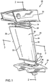
- FIG. 1 shows a vane 20 having an airfoil 22 extending from an inboard end at an inboard platform 24 to an outboard end at an outboard shroud 26.
- the airfoil 22 has a leading edge 28, a trailing edge 30, and pressure and suction side surfaces 32 and 34 extending between the leading and trailing edges.
- the exemplary platform and shroud form segments of an annulus so that a circumferential array of such vanes may be assembled with shrouds and platforms sealed/mated edge-to-edge.
- the exemplary vane 20 is an assembly wherein the shroud, platform, and airfoil are separately formed and then secured to each other.
- FIGS. 1-3 show the airfoil as comprising a thin-walled shell 50 and a structural spar 52 within the shell.
- the shell material is a CMC.
- the shell may be manufactured by various CMC fabrication methods. These typically involve forming a preform of ceramic fiber (e.g., SiC) in the shape of the airfoil (e.g., by weaving or other technique) and infiltrating the preform with matrix material (e.g., also SiC). Prior to infiltration, the preform may be coated for limiting bonding with the matrix (e.g., with BN by chemical vapor deposition (CVD)).
- Exemplary infiltration techniques include chemical vapor infiltration, slurry infiltration-sintering, polymer-impregnation-pyrolysis, slurry casting, and melt infiltration.
- Exemplary spar material is a metal alloy (e.g., a cast nickel-based superalloy).
- Inboard and outboard seals 53 and 54 respectively seal between inboard and outboard ends 55 and 56 of the shell and the adjacent platform and shroud.
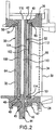
- An outboard end portion 40 ( FIG. 2 ) of the spar 52 may be mounted to the shroud 26.
- the portion 40 is received in an aperture formed by a surface 42 and welded thereto.
- a threaded stud 44 is formed at the inboard end of the spar 52 and extends through an aperture in the platform 24 formed by a surface 45.
- a nut 46 and washers 47 may engage the stud and an inboard surface of the platform while a shoulder 48 of the spar bears up against a mating shoulder 49 of the platform.
- the spar may thus form the principal mechanical coupling between shroud and platform.
- the shell may be positioned relative to the spar by one or more of several mechanisms.
- the shell flanges 55 and 56 may be located by appropriate channels 57 ( FIG. 1 ) and 58 ( FIG. 2 ) in the platform and shroud, respectively.
- spacers or seal/spacer units such as seals 53 and 54 may be positioned between the platform/shroud 24,26 and the shell 50.
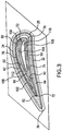
- the shell exterior surface ( FIG. 3 ) defines the leading and trailing edges 28 and 30 and pressure and suction sides 32 and 34.
- the shell interior surface includes a first portion 60 along the pressure side and a second portion 62 along the suction side. These define adjacent pressure and suction sidewall portions 64 and 66, respectively, which directly merge at the leading edge and merge more gradually toward the trailing edge.
- the spar 52 has an exterior surface in close facing spaced-apart relation to the shell interior surface.
- the spar exterior surface has a leading edge 70, a trailing edge 72, and pressure and suction side portions 74 and 76.
- Seals 80 and 82 extend generally spanwise between the spar exterior surface and shell interior surface. The exemplary two seals separate the gap between the shell and spar into first and second cavities 90 and 92.
- the cavities 90 and 92 are fed with air from chambers/cavities/plena (discussed below) within the spar 52.
- the exemplary spar 52 has a sidewall with pressure and suction side portions 100 and 102.
- the exemplary spar 52 includes an internal wall 104 extending from a first junction 106 with the spar sidewall proximate the leading edge to a second junction 108 with the spar sidewall along a trailing portion of the pressure side 102.
- the wall 104 thus divides the spar interior into a second chamber 110 and a first chamber 112.
- the exemplary second chamber 110 extends essentially along a slight majority of the pressure side of the spar.
- the exemplary first chamber 112 is essentially entirely along the suction side of the spar.
- These chambers 110 and 112 may feed cooling air to the adjacent cavities 90 and 92 through arrays of fine apertures (not shown) in the spar sidewall.
- the air introduced to the cavities 90 and 92 may flow generally downstream (toward the trailing edge) and may exit through trailing edge outlets (not shown) in the shell. To flow in this way, the air may thus leak through one or both of the seals (e.g., air from a cavity 90 leaking through the seal 80).
- the chambers 110 and 112 may be fed with cooling air via associated ports in one or both of the platform and shroud.
- FIG. 2 shows a first port 114 in the platform for feeding the first chamber 112 and a port 116 in the shroud and spar outboard end for feeding the second chamber 110.
- the ability to introduce air of different pressure and/or temperature to the two chambers 110 and 112 adds flexibility in the selection of appropriate air flow rates, temperatures, and pressures in the cavities 90 and 92 so as to appropriately counteract both thermal and mechanical stresses.
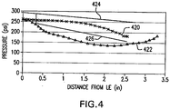
- FIG. 4 shows streamwise pressure distribution at an exemplary spanwise position along the shell.
- An external pressure along the airfoil pressure side 32 is shown as 420 and an external suction side 34 pressure is shown as 422. At the leading edge 28, these merge to the stagnation pressure.
- the internal pressure may be a function of the cooling supply pressure in view of the throttling through the spar holes.
- internal pressure would be substantially constant along both pressure and suction sides of the shell (e.g., with a small upstream-to-downstream decrease due to flow losses).
- the internal pressure might be slightly above the stagnation pressure (e.g., 2-3% to avoid hot gas ingestion in the event of shell cracking).
- the internal-to-external pressure difference would produce a mechanical stress which, combined with thermal stresses, may exceed design thresholds for the shell.
- the presence of the seals 80 and 82 forming the multiple spar-to-shell gap cavities 90 and 92 permits the maintenance of different internal pressures at different locations along the shell.
- an additional degree of flexibility is provided by at least partially further decoupling the pressure in each cavity 90 and 92 from the amount of cooling of the shell along that cavity.
- the internal pressure side pressure 424 remains substantially constant because the entirety of this portion of the shell falls along the first cavity.
- the suction side pressure 426 dips in the region associated with the second cavity. This allows this pressure 426 to more closely accommodate the pressure 422 to reduce the mechanical stress component.
- the distances from the leading edge for the internal pressures are the distances along the spar exterior surface.
- the pressure fed to the second chamber 112 may be less than the pressure fed to the first chamber 110.
- an exemplary pressure difference is at least 5psi (34.5 x 10 3 Nm -2 )(e.g., 5-50psi (34.5-345 x 10 3 Nm -2 ) and, more narrowly 5-10psi (34.5-69.0 x 10 3 Nm -2 )). Percentage-wise, this pressure difference may be at least 1.5% (e.g., 1.5-15%).
- the second chamber 112 may be fed with bleed air from one or more of the relatively early/upstream compressor stages while the first chamber 110 is fed with bleed air from later/downstream compressor stages where both pressure and temperature are higher.
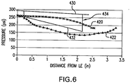
- FIG. 5 shows an alternate spar 140 having a sidewall with pressure and suction side portions 142 and 144.
- An exemplary spar 140 includes an internal wall 146 extending from a first junction 148 with the spar sidewall proximate the leading edge to a second junction 150 with the spar sidewall along the suction side 144.
- the wall 146 divides the spar interior into a second chamber 152 and a first chamber 154.
- the exemplary second chamber 152 extends essentially along the entirety of the pressure side and along small leading and trailing portions of the suction side.
- the exemplary first chamber 154 is essentially entire along the suction side. These chambers 152 and 154 may feed cooling air to the adjacent cavities 156 and 158.
- the exemplary cavities are separated by seals 160 and 162 and may be fed similarly to the respective cavities of the FIG. 3 embodiment.
- the first seal 160 is positioned slightly to the suction side of the leading edge.
- the second seal 162 is positioned at an intermediate location along the suction side (e.g., between about 50% and 70% of the streamwise length along the suction side).
- FIG. 6 shows pressure and suction side internal pressures 430 and 432 for the airfoil of FIG. 5 . Due to the presence in the second seal 162, there is an abrupt jump 434 in the suction side pressure 432 to essentially merge with the pressure side distribution downstream of the second seal 162.
- FIG. 7 shows an airfoil having a similar shell and spar to those of FIG. 5 but having a greater number of seals forming a greater number of cavities.
- seals 180 and 182 are similarly positioned to the seals 160 and 162 of FIG. 5 .
- the associated cavities are further subdivided by an exemplary group of seals 189, 186, 188, and 190 along the pressure side and an exemplary single seal 192 along the suction side.
- a series of cavities 200, 202, 204, 206, and 208 replace the cavity 156 and a pair of cavities 210 and 212 replace the cavity 158.
- FIG. 8 again shows the basic external pressures 420 and 422.
- the internal pressures 464 on the pressure side and 466 on the suction side of the FIG. 7 airfoil show a greater number of steps than the pressures of FIG. 6 .
- the steps correspond to the cavity-to-cavity transitions and permit the pressure distributions to more closely correspond to the associated external pressures to further reduce the pressure difference across the shell wall.
- the invention may be implemented in the reengineering of a given vane.
- the reengineering may preserve the basic external profile of the shell.
- the reengineering may also preserve the internal profile.
- internal changes including wall thinning may be particularly appropriate in view of the available stress reduction.
- the reengineering may also eliminate other internal strengthening features such as tensile ribs/webs, locally thickened areas, and the like.
- the reengineering may also more substantially alter the spar structure.
- the reengineering may replace a multi-piece spar with a single piece spar.
- the reengineering may replace the combination of a single spar and non-structural filler component with a single spar.
- the reengineered vane may be used in the remanufacturing of a given gas turbine engine.
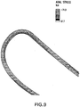
- FIG. 9 plots axial stress along a leading portion of the shell of a baseline airfoil with substantially constant internal pressure slightly above the stagnation pressure.
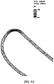
- FIG. 10 shows the interlaminar tensile stress.
- FIGS. 11 and 12 show the corresponding axial and interlaminar tensile stresses, respectively. Peak magnitudes of the stresses appear substantially reduced.
Claims (6)
- Schaufel (20), umfassend:eine Flügelhülle (50), die im Wesentlichen aus einem Keramik-Matrix-Verbundmaterial besteht und Folgendes aufweist:eine Vorderkante (28);eine Hinterkante (30);eine Druckseite (32); undeine Saugseite (34);einen Strukturholm (52, 140) innerhalb der Hülle (50);eine Außenverkleidung (26) an einem Außenende der Hülle (50); undeine Innenplattform (24) an einem Innenende der Hülle (50),wobei der Holm (52, 140) eine Innenwand (104, 146) umfasst, dadurch gekennzeichnet, dass die Innenwand den Innenraum des Holms in eine erste Kammer (112, 154) im Wesentlichen entlang der Saugseite (34) und eine zweite Kammer (110, 152) entlang der Druckseite (32) gegenüber der ersten Kammer teilt; und
die Schaufel (20) ferner eine Vielzahl von Dichtungen (80, 82, 160, 162, 180, 182, 186, 188, 189, 190,192) zwischen der Hülle (50) und dem Holm (52, 140) umfasst, wobei die Vielzahl von Dichtungen mindestens einen ersten Hohlraum (92, 158, 210, 212) zwischen der Saugseite (34) der Hülle (50) und dem Holm (52, 140) bilden und einen zweiten Hohlraum (90, 156, 200, 204, 206, 208) zwischen der Druckseite (32) der Hülle (50) und dem Holm (52, 140), wobei der erste Hohlraum (92 ... 212) in Fluidverbindung mit der ersten Kammer (112, 154) ist und der zweite Hohlraum (90 ... 208) in Fluidverbindung mit der zweiten Kammer (110, 152) ist, sodass der erste und der zweite Hohlraum von der ersten und der zweiten Kammer bei verschiedenen Drücken und/oder Temperaturen mit Luft versorgt werden können. - Schaufel (20) nach Anspruch 1, wobei:der Holm im Wesentlichen aus einem ersten metallischen Gussteil besteht;die Plattform (24) im Wesentlichen auf einem zweiten metallischen Gussteil besteht; unddie Verkleidung (26) im Wesentlichen aus einem dritten metallischen Gussteil besteht.
- Schaufel (20) nach Anspruch 1 oder 2, wobei:der Holm (52, 140) eine Seitenwand umfasst, die Folgendes aufweist:eine Vorderkante;eine Hinterkante;eine Druckseite (100, 142); undeine Saugseite (102, 144); und,wobei der Hülle dehnbare Bahnen fehlen, die die Druck- und die Saugseite der Hülle verbinden.
- Schaufel (20) nach einem der Ansprüche 1 bis 3, wobei:der Holm (52, 140) eine Seitenwand umfasst, die Folgendes aufweist:eine Vorderkante;eine Hinterkante;eine Druckseite (100, 142); undeine Saugseite (102, 144); und,wobei die erste Holmkammer (112, 154) durch die Innenwand (104, 146) gebildet wird, die sich von der Nähe der Holmvorderkante zur Holmseitenwand an der Saugseite (102, 144) erstreckt.
- Schaufel (20) nach einem der vorstehenden Ansprüche, wobei die Vielzahl von Dichtungen (80 ... 192) mindestens eine von keramischen Schnurdichtungen und metallischen Balgdichtungen umfasst.
- Schaufel (20) nach einem der vorstehenden Ansprüche, wobei der erste Hohlraum (92, 212) entlang der Saugseite (34) stromabwärts von der Vorderkante (28) beginnt und an der Hinterkante (30) oder entlang der Saugseite (34) stromaufwärts von der Hinterkante (30) endet.
Applications Claiming Priority (1)
| Application Number | Priority Date | Filing Date | Title |
|---|---|---|---|
| US11/417,972 US7452189B2 (en) | 2006-05-03 | 2006-05-03 | Ceramic matrix composite turbine engine vane |
Publications (3)
| Publication Number | Publication Date |
|---|---|
| EP1852572A2 EP1852572A2 (de) | 2007-11-07 |
| EP1852572A3 EP1852572A3 (de) | 2010-10-06 |
| EP1852572B1 true EP1852572B1 (de) | 2017-01-11 |
Family
ID=38356211
Family Applications (1)
| Application Number | Title | Priority Date | Filing Date |
|---|---|---|---|
| EP07250882.3A Active EP1852572B1 (de) | 2006-05-03 | 2007-03-02 | Keramik-Matrix-Verbund-Turbinenleitschaufel |
Country Status (3)
| Country | Link |
|---|---|
| US (1) | US7452189B2 (de) |
| EP (1) | EP1852572B1 (de) |
| JP (1) | JP2007298024A (de) |
Families Citing this family (84)
| Publication number | Priority date | Publication date | Assignee | Title |
|---|---|---|---|---|
| US8528339B2 (en) * | 2007-04-05 | 2013-09-10 | Siemens Energy, Inc. | Stacked laminate gas turbine component |
| DE102007027465A1 (de) | 2007-06-14 | 2008-12-18 | Rolls-Royce Deutschland Ltd & Co Kg | Gasturbinenschaufel mit modularem Aufbau |
| US8206118B2 (en) * | 2008-01-04 | 2012-06-26 | United Technologies Corporation | Airfoil attachment |
| US8142163B1 (en) * | 2008-02-01 | 2012-03-27 | Florida Turbine Technologies, Inc. | Turbine blade with spar and shell |
| US20090202355A1 (en) * | 2008-02-11 | 2009-08-13 | Rolls-Royce North American Technologies, Inc. | Replaceable blade tip shroud |
| US8956105B2 (en) * | 2008-12-31 | 2015-02-17 | Rolls-Royce North American Technologies, Inc. | Turbine vane for gas turbine engine |
| US8251651B2 (en) | 2009-01-28 | 2012-08-28 | United Technologies Corporation | Segmented ceramic matrix composite turbine airfoil component |
| JP5321186B2 (ja) | 2009-03-26 | 2013-10-23 | 株式会社Ihi | Cmcタービン静翼 |
| JP5311126B2 (ja) * | 2009-03-26 | 2013-10-09 | 株式会社Ihi | Cmcタービン静翼 |
| WO2010131385A1 (ja) * | 2009-05-11 | 2010-11-18 | 三菱重工業株式会社 | タービン静翼およびガスタービン |
| EP2295722B1 (de) * | 2009-09-09 | 2019-11-06 | Ansaldo Energia IP UK Limited | Schaufel einer Turbine |
| US8511969B2 (en) * | 2009-10-01 | 2013-08-20 | Pratt & Whitney Canada Corp. | Interturbine vane with multiple air chambers |
| US9890647B2 (en) * | 2009-12-29 | 2018-02-13 | Rolls-Royce North American Technologies Inc. | Composite gas turbine engine component |
| US9080448B2 (en) * | 2009-12-29 | 2015-07-14 | Rolls-Royce North American Technologies, Inc. | Gas turbine engine vanes |
| US8777583B2 (en) * | 2010-12-27 | 2014-07-15 | General Electric Company | Turbine airfoil components containing ceramic-based materials and processes therefor |
| US8790067B2 (en) | 2011-04-27 | 2014-07-29 | United Technologies Corporation | Blade clearance control using high-CTE and low-CTE ring members |
| FR2974593B1 (fr) * | 2011-04-28 | 2015-11-13 | Snecma | Moteur a turbine comportant une protection metallique d'une piece composite |
| US8739547B2 (en) | 2011-06-23 | 2014-06-03 | United Technologies Corporation | Gas turbine engine joint having a metallic member, a CMC member, and a ceramic key |
| US8864492B2 (en) | 2011-06-23 | 2014-10-21 | United Technologies Corporation | Reverse flow combustor duct attachment |
| US9726028B2 (en) | 2011-06-29 | 2017-08-08 | Siemens Energy, Inc. | Ductile alloys for sealing modular component interfaces |
| US8511975B2 (en) | 2011-07-05 | 2013-08-20 | United Technologies Corporation | Gas turbine shroud arrangement |
| US9335051B2 (en) | 2011-07-13 | 2016-05-10 | United Technologies Corporation | Ceramic matrix composite combustor vane ring assembly |
| US8920127B2 (en) | 2011-07-18 | 2014-12-30 | United Technologies Corporation | Turbine rotor non-metallic blade attachment |
| EP2831306B1 (de) | 2012-03-28 | 2017-06-28 | Ansaldo Energia IP UK Limited | Verfahren zur abtrennung eines metallteils von einem keramikteil |
| EP2830805B1 (de) | 2012-03-28 | 2019-07-31 | Ansaldo Energia IP UK Limited | Verfahren zur verarbeitung einer modularen hybriden komponente |
| US9546557B2 (en) * | 2012-06-29 | 2017-01-17 | General Electric Company | Nozzle, a nozzle hanger, and a ceramic to metal attachment system |
| WO2014126708A1 (en) | 2013-02-18 | 2014-08-21 | United Technologies Corporation | Stress mitigation feature for composite airfoil leading edge |
| US9556750B2 (en) * | 2013-03-04 | 2017-01-31 | Rolls-Royce North American Technologies, Inc. | Compartmentalization of cooling air flow in a structure comprising a CMC component |
| WO2014158277A2 (en) | 2013-03-04 | 2014-10-02 | Freeman Ted J | Method for making gas turbine engine ceramic matrix composite airfoil |
| EP2971540A2 (de) * | 2013-03-14 | 2016-01-20 | Rolls-Royce Corporation | Zweifach gegossene turbinenschaufel |
| WO2014197105A2 (en) | 2013-03-25 | 2014-12-11 | United Technologies Corporation | Non-integral blade and platform segment for rotor |
| EP3049627B1 (de) * | 2013-09-24 | 2019-10-30 | United Technologies Corporation | Komponente einer gasturbine und herstellungsverfahren dafür |
| DE102013219774A1 (de) * | 2013-09-30 | 2015-04-02 | MTU Aero Engines AG | Schaufel für eine Gasturbine |
| US9896943B2 (en) * | 2014-05-12 | 2018-02-20 | Honeywell International Inc. | Gas path components of gas turbine engines and methods for cooling the same using porous medium cooling systems |
| US10094239B2 (en) * | 2014-10-31 | 2018-10-09 | Rolls-Royce North American Technologies Inc. | Vane assembly for a gas turbine engine |
| US10202854B2 (en) * | 2014-12-18 | 2019-02-12 | Rolls-Royce North America Technologies, Inc. | Abrasive tips for ceramic matrix composite blades and methods for making the same |
| US9995160B2 (en) * | 2014-12-22 | 2018-06-12 | General Electric Company | Airfoil profile-shaped seals and turbine components employing same |
| EP3048254B1 (de) * | 2015-01-22 | 2017-12-27 | Rolls-Royce Corporation | Schaufelanordnung für einen gasturbinenmotor |
| US10329950B2 (en) * | 2015-03-23 | 2019-06-25 | Rolls-Royce North American Technologies Inc. | Nozzle guide vane with composite heat shield |
| US9915151B2 (en) | 2015-05-26 | 2018-03-13 | Rolls-Royce Corporation | CMC airfoil with cooling channels |
| US11035247B2 (en) | 2016-04-01 | 2021-06-15 | General Electric Company | Turbine apparatus and method for redundant cooling of a turbine apparatus |
| US10294807B2 (en) | 2016-05-19 | 2019-05-21 | Honeywell International Inc. | Inter-turbine ducts |
| US10590776B2 (en) | 2016-06-06 | 2020-03-17 | General Electric Company | Turbine component and methods of making and cooling a turbine component |
| US10436062B2 (en) * | 2016-11-17 | 2019-10-08 | United Technologies Corporation | Article having ceramic wall with flow turbulators |
| US10746038B2 (en) * | 2016-11-17 | 2020-08-18 | Raytheon Technologies Corporation | Airfoil with airfoil piece having radial seal |
| US10260363B2 (en) | 2016-12-08 | 2019-04-16 | General Electric Company | Additive manufactured seal for insert compartmentalization |
| US10767502B2 (en) | 2016-12-23 | 2020-09-08 | Rolls-Royce Corporation | Composite turbine vane with three-dimensional fiber reinforcements |
| US10851658B2 (en) | 2017-02-06 | 2020-12-01 | General Electric Company | Nozzle assembly and method for forming nozzle assembly |
| US10724380B2 (en) * | 2017-08-07 | 2020-07-28 | General Electric Company | CMC blade with internal support |
| FR3070422B1 (fr) * | 2017-08-22 | 2021-07-23 | Safran Aircraft Engines | Attache poignard avec joint d'une aube de redresseur |
| EP3717746A1 (de) * | 2017-12-01 | 2020-10-07 | Siemens Energy, Inc. | Eingelötetes wärmetransfermerkmal für gekühlte turbinenkomponenten |
| US10697310B2 (en) * | 2018-05-17 | 2020-06-30 | Raytheon Technologies Corporation | Multiple source impingement baffles for gas turbine engine components |
| US10612399B2 (en) * | 2018-06-01 | 2020-04-07 | Rolls-Royce North American Technologies Inc. | Turbine vane assembly with ceramic matrix composite components |
| US10808560B2 (en) * | 2018-06-20 | 2020-10-20 | Rolls-Royce Corporation | Turbine vane assembly with ceramic matrix composite components |
| US11008888B2 (en) * | 2018-07-17 | 2021-05-18 | Rolls-Royce Corporation | Turbine vane assembly with ceramic matrix composite components |
| US11149567B2 (en) | 2018-09-17 | 2021-10-19 | Rolls-Royce Corporation | Ceramic matrix composite load transfer roller joint |
| US11046620B2 (en) | 2018-10-18 | 2021-06-29 | Rolls-Royce Corporation | Method of processing a ceramic matrix composite (CMC) component |
| US11820716B2 (en) | 2018-10-18 | 2023-11-21 | Rolls Royce North American Technologies Inc. | Method of fabricating cooling features on a ceramic matrix composite (CMC) component |
| US10906842B2 (en) | 2018-10-18 | 2021-02-02 | Rolls-Royce High Temperature Composites Inc. | Method of processing a ceramic matrix composite (CMC) component |
| US10752556B2 (en) | 2018-10-18 | 2020-08-25 | Rolls-Royce High Temperature Composites Inc. | Method of processing a ceramic matrix composite (CMC) component |
| US11149568B2 (en) | 2018-12-20 | 2021-10-19 | Rolls-Royce Plc | Sliding ceramic matrix composite vane assembly for gas turbine engines |
| US10767495B2 (en) * | 2019-02-01 | 2020-09-08 | Rolls-Royce Plc | Turbine vane assembly with cooling feature |
| US20200248568A1 (en) * | 2019-02-01 | 2020-08-06 | Rolls-Royce Plc | Turbine vane assembly with ceramic matrix composite components and temperature management features |
| US10975708B2 (en) * | 2019-04-23 | 2021-04-13 | Rolls-Royce Plc | Turbine section assembly with ceramic matrix composite vane |
| US11193381B2 (en) | 2019-05-17 | 2021-12-07 | Rolls-Royce Plc | Turbine vane assembly having ceramic matrix composite components with sliding support |
| US10890076B1 (en) | 2019-06-28 | 2021-01-12 | Rolls-Royce Plc | Turbine vane assembly having ceramic matrix composite components with expandable spar support |
| US11286798B2 (en) | 2019-08-20 | 2022-03-29 | Rolls-Royce Corporation | Airfoil assembly with ceramic matrix composite parts and load-transfer features |
| US11149560B2 (en) | 2019-08-20 | 2021-10-19 | Rolls-Royce Plc | Airfoil assembly with ceramic matrix composite parts and load-transfer features |
| EP3805525A1 (de) | 2019-10-09 | 2021-04-14 | Rolls-Royce plc | Turbinenschaufelanordnung mit keramikmatrixverbundwerkstoffen |
| US11255204B2 (en) | 2019-11-05 | 2022-02-22 | Rolls-Royce Plc | Turbine vane assembly having ceramic matrix composite airfoils and metallic support spar |
| US11156105B2 (en) * | 2019-11-08 | 2021-10-26 | Raytheon Technologies Corporation | Vane with seal |
| US11174794B2 (en) * | 2019-11-08 | 2021-11-16 | Raytheon Technologies Corporation | Vane with seal and retainer plate |
| US10975709B1 (en) | 2019-11-11 | 2021-04-13 | Rolls-Royce Plc | Turbine vane assembly with ceramic matrix composite components and sliding support |
| US11454127B2 (en) * | 2019-11-22 | 2022-09-27 | Pratt & Whitney Canada Corp. | Vane for gas turbine engine |
| FR3107299B1 (fr) * | 2020-02-14 | 2022-03-11 | Safran Aircraft Engines | Aube en matériau composite pour stator de turbomachine comprenant un noyau creux en plastique non poreux |
| US11391163B1 (en) * | 2021-03-05 | 2022-07-19 | Raytheon Technologies Corporation | Vane arc segment with seal |
| US11536145B2 (en) * | 2021-04-09 | 2022-12-27 | Raytheon Technologies Corporation | Ceramic component with support structure |
| US11549385B2 (en) * | 2021-05-04 | 2023-01-10 | Raytheon Technologies Corporation | Airfoil assembly with seal plate and seal |
| US11519280B1 (en) | 2021-09-30 | 2022-12-06 | Rolls-Royce Plc | Ceramic matrix composite vane assembly with compliance features |
| US11560799B1 (en) | 2021-10-22 | 2023-01-24 | Rolls-Royce High Temperature Composites Inc. | Ceramic matrix composite vane assembly with shaped load transfer features |
| US11591921B1 (en) | 2021-11-05 | 2023-02-28 | Rolls-Royce Plc | Ceramic matrix composite vane assembly |
| US11732596B2 (en) | 2021-12-22 | 2023-08-22 | Rolls-Royce Plc | Ceramic matrix composite turbine vane assembly having minimalistic support spars |
| US11773737B1 (en) | 2022-04-29 | 2023-10-03 | Rolls-Royce Plc | Load transfer device, stator vane assembly, turbine, and gas turbine engine including the same |
| US11802487B1 (en) * | 2022-08-15 | 2023-10-31 | Rtx Corporation | Gas turbine engine stator vane formed of ceramic matrix composites and having attachment flanges |
Family Cites Families (25)
| Publication number | Priority date | Publication date | Assignee | Title |
|---|---|---|---|---|
| US2497041A (en) * | 1945-03-27 | 1950-02-07 | United Aircraft Corp | Nozzle ring for gas turbines |
| US3240468A (en) * | 1964-12-28 | 1966-03-15 | Curtiss Wright Corp | Transpiration cooled blades for turbines, compressors, and the like |
| US3963368A (en) * | 1967-12-19 | 1976-06-15 | General Motors Corporation | Turbine cooling |
| GB1587401A (en) * | 1973-11-15 | 1981-04-01 | Rolls Royce | Hollow cooled vane for a gas turbine engine |
| US4312624A (en) * | 1980-11-10 | 1982-01-26 | United Technologies Corporation | Air cooled hollow vane construction |
| DE3110098C2 (de) * | 1981-03-16 | 1983-03-17 | MTU Motoren- und Turbinen-Union München GmbH, 8000 München | Turbinenleitschaufel für Gasturbinentriebwerke |
| GB2107405B (en) * | 1981-10-13 | 1985-08-14 | Rolls Royce | Nozzle guide vane for a gas turbine engine |
| CA1193551A (en) * | 1981-12-31 | 1985-09-17 | Paul C. Holden | Shell-spar cooled airfoil having variable coolant passageway area |
| FR2725474B1 (fr) * | 1984-03-14 | 1996-12-13 | Snecma | Aube de distributeur de turbine refroidie |
| JPS6189908A (ja) * | 1984-10-11 | 1986-05-08 | Central Res Inst Of Electric Power Ind | セラミツクス金属複合静翼構造 |
| US5356265A (en) | 1992-08-25 | 1994-10-18 | General Electric Company | Chordally bifurcated turbine blade |
| US5820337A (en) * | 1995-01-03 | 1998-10-13 | General Electric Company | Double wall turbine parts |
| FR2743391B1 (fr) * | 1996-01-04 | 1998-02-06 | Snecma | Aube refrigeree de distributeur de turbine |
| US5630700A (en) | 1996-04-26 | 1997-05-20 | General Electric Company | Floating vane turbine nozzle |
| US6224339B1 (en) * | 1998-07-08 | 2001-05-01 | Allison Advanced Development Company | High temperature airfoil |
| US6283708B1 (en) | 1999-12-03 | 2001-09-04 | United Technologies Corporation | Coolable vane or blade for a turbomachine |
| US6514046B1 (en) | 2000-09-29 | 2003-02-04 | Siemens Westinghouse Power Corporation | Ceramic composite vane with metallic substructure |
| US6428273B1 (en) * | 2001-01-05 | 2002-08-06 | General Electric Company | Truncated rib turbine nozzle |
| US6464456B2 (en) | 2001-03-07 | 2002-10-15 | General Electric Company | Turbine vane assembly including a low ductility vane |
| US6709230B2 (en) | 2002-05-31 | 2004-03-23 | Siemens Westinghouse Power Corporation | Ceramic matrix composite gas turbine vane |
| US6648597B1 (en) | 2002-05-31 | 2003-11-18 | Siemens Westinghouse Power Corporation | Ceramic matrix composite turbine vane |
| US7093359B2 (en) | 2002-09-17 | 2006-08-22 | Siemens Westinghouse Power Corporation | Composite structure formed by CMC-on-insulation process |
| GB2402717B (en) | 2003-06-10 | 2006-05-10 | Rolls Royce Plc | A vane assembly for a gas turbine engine |
| US20050158171A1 (en) | 2004-01-15 | 2005-07-21 | General Electric Company | Hybrid ceramic matrix composite turbine blades for improved processibility and performance |
| US7094021B2 (en) * | 2004-02-02 | 2006-08-22 | General Electric Company | Gas turbine flowpath structure |
-
2006
- 2006-05-03 US US11/417,972 patent/US7452189B2/en active Active
-
2007
- 2007-02-26 JP JP2007044935A patent/JP2007298024A/ja active Pending
- 2007-03-02 EP EP07250882.3A patent/EP1852572B1/de active Active
Non-Patent Citations (1)
| Title |
|---|
| None * |
Also Published As
| Publication number | Publication date |
|---|---|
| EP1852572A3 (de) | 2010-10-06 |
| US7452189B2 (en) | 2008-11-18 |
| US20070258811A1 (en) | 2007-11-08 |
| JP2007298024A (ja) | 2007-11-15 |
| EP1852572A2 (de) | 2007-11-07 |
Similar Documents
| Publication | Publication Date | Title |
|---|---|---|
| EP1852572B1 (de) | Keramik-Matrix-Verbund-Turbinenleitschaufel | |
| EP2009243B1 (de) | Keramische Matrix-Verbund-Turbinenleitschaufel | |
| EP2039884B1 (de) | Keramik-Matrix-Verbund-Turbinenleitschaufel | |
| JP4559751B2 (ja) | ガスタービンエンジンのタービンノズルの二又状インピンジメントバッフル | |
| US7452182B2 (en) | Multi-piece turbine vane assembly | |
| CA2736790C (en) | Turbine shroud sealing apparatus | |
| US20170356296A1 (en) | Gas turbine engine component | |
| EP2599959B1 (de) | Keramikmatrix-Verbundstrukturen einer Schaufel mit Verstärkungs- Hinterkante für Gasturbinenmotor | |
| JP4049754B2 (ja) | タービンノズルセグメントの片持ち式支持 | |
| EP3575558B1 (de) | Dichtungsanordnung für gasturbinentriebwerke und entsprechendes dichtungsverfahren | |
| US10415403B2 (en) | Cooled blisk for gas turbine engine | |
| US20070258809A1 (en) | Multi-layer ring seal | |
| US11732597B2 (en) | Double box composite seal assembly with insert for gas turbine engine | |
| US11788467B2 (en) | Bladed rotor wheel | |
| US10801349B2 (en) | Ceramic matrix composite blade outer air seal | |
| EP3798421B1 (de) | Doppelkammerverbunddichtungsanordnung mit faserdichteanordnung für gasturbinentriebwerk, gasturbinentriebwerk und verfahren | |
| EP3798420B1 (de) | Doppelkastenverbunddichtungsanordnung für gasturbinenmotor, gasturbinenmotor und verfahren | |
| EP3808942B1 (de) | Leitschaufelprofil, bauteil mit schaufelprofil und verfahren zum zusammenbauen eines leitschaufelprofils aus keramikmatrixverbund | |
| US20220090505A1 (en) | Airfoil having cavity insert to separate flow | |
| Shi et al. | Ceramic matrix composite turbine engine vane | |
| US11401834B2 (en) | Method of securing a ceramic matrix composite (CMC) component to a metallic substructure using CMC straps | |
| EP3789585B1 (de) | Schaufelblatt mit metallabschirmung | |
| Prill et al. | Ceramic matrix composite turbine engine vane | |
| Schaff et al. | Ceramic matrix composite turbine engine vane |
Legal Events
| Date | Code | Title | Description |
|---|---|---|---|
| PUAI | Public reference made under article 153(3) epc to a published international application that has entered the european phase |
Free format text: ORIGINAL CODE: 0009012 |
|
| AK | Designated contracting states |
Kind code of ref document: A2 Designated state(s): AT BE BG CH CY CZ DE DK EE ES FI FR GB GR HU IE IS IT LI LT LU LV MC MT NL PL PT RO SE SI SK TR |
|
| AX | Request for extension of the european patent |
Extension state: AL BA HR MK YU |
|
| PUAL | Search report despatched |
Free format text: ORIGINAL CODE: 0009013 |
|
| AK | Designated contracting states |
Kind code of ref document: A3 Designated state(s): AT BE BG CH CY CZ DE DK EE ES FI FR GB GR HU IE IS IT LI LT LU LV MC MT NL PL PT RO SE SI SK TR |
|
| AX | Request for extension of the european patent |
Extension state: AL BA HR MK RS |
|
| 17P | Request for examination filed |
Effective date: 20110406 |
|
| AKX | Designation fees paid |
Designated state(s): DE GB |
|
| 17Q | First examination report despatched |
Effective date: 20131210 |
|
| GRAP | Despatch of communication of intention to grant a patent |
Free format text: ORIGINAL CODE: EPIDOSNIGR1 |
|
| INTG | Intention to grant announced |
Effective date: 20160728 |
|
| RAP1 | Party data changed (applicant data changed or rights of an application transferred) |
Owner name: UNITED TECHNOLOGIES CORPORATION |
|
| GRAS | Grant fee paid |
Free format text: ORIGINAL CODE: EPIDOSNIGR3 |
|
| GRAA | (expected) grant |
Free format text: ORIGINAL CODE: 0009210 |
|
| AK | Designated contracting states |
Kind code of ref document: B1 Designated state(s): DE GB |
|
| REG | Reference to a national code |
Ref country code: GB Ref legal event code: FG4D |
|
| REG | Reference to a national code |
Ref country code: DE Ref legal event code: R096 Ref document number: 602007049482 Country of ref document: DE |
|
| REG | Reference to a national code |
Ref country code: DE Ref legal event code: R082 Ref document number: 602007049482 Country of ref document: DE Representative=s name: SCHMITT-NILSON SCHRAUD WAIBEL WOHLFROM PATENTA, DE |
|
| REG | Reference to a national code |
Ref country code: DE Ref legal event code: R097 Ref document number: 602007049482 Country of ref document: DE |
|
| PLBE | No opposition filed within time limit |
Free format text: ORIGINAL CODE: 0009261 |
|
| STAA | Information on the status of an ep patent application or granted ep patent |
Free format text: STATUS: NO OPPOSITION FILED WITHIN TIME LIMIT |
|
| 26N | No opposition filed |
Effective date: 20171012 |
|
| REG | Reference to a national code |
Ref country code: DE Ref legal event code: R081 Ref document number: 602007049482 Country of ref document: DE Owner name: RAYTHEON TECHNOLOGIES CORPORATION (N.D.GES.D.S, US Free format text: FORMER OWNER: UNITED TECHNOLOGIES CORPORATION, FARMINGTON, CONN., US |
|
| PGFP | Annual fee paid to national office [announced via postgrant information from national office to epo] |
Ref country code: GB Payment date: 20230222 Year of fee payment: 17 Ref country code: DE Payment date: 20230221 Year of fee payment: 17 |
|
| P01 | Opt-out of the competence of the unified patent court (upc) registered |
Effective date: 20230519 |