EP1852348A2 - Blitzschutzsystem für Betanken während des Fluges - Google Patents
Blitzschutzsystem für Betanken während des Fluges Download PDFInfo
- Publication number
- EP1852348A2 EP1852348A2 EP07251862A EP07251862A EP1852348A2 EP 1852348 A2 EP1852348 A2 EP 1852348A2 EP 07251862 A EP07251862 A EP 07251862A EP 07251862 A EP07251862 A EP 07251862A EP 1852348 A2 EP1852348 A2 EP 1852348A2
- Authority
- EP
- European Patent Office
- Prior art keywords
- refueling
- aircraft
- inert gas
- fuel
- fluid
- Prior art date
- Legal status (The legal status is an assumption and is not a legal conclusion. Google has not performed a legal analysis and makes no representation as to the accuracy of the status listed.)
- Granted
Links
Images

Classifications
-
- B—PERFORMING OPERATIONS; TRANSPORTING
- B64—AIRCRAFT; AVIATION; COSMONAUTICS
- B64D—EQUIPMENT FOR FITTING IN OR TO AIRCRAFT; FLIGHT SUITS; PARACHUTES; ARRANGEMENT OR MOUNTING OF POWER PLANTS OR PROPULSION TRANSMISSIONS IN AIRCRAFT
- B64D39/00—Refuelling during flight
- B64D39/04—Adaptations of hose construction
-
- B—PERFORMING OPERATIONS; TRANSPORTING
- B64—AIRCRAFT; AVIATION; COSMONAUTICS
- B64D—EQUIPMENT FOR FITTING IN OR TO AIRCRAFT; FLIGHT SUITS; PARACHUTES; ARRANGEMENT OR MOUNTING OF POWER PLANTS OR PROPULSION TRANSMISSIONS IN AIRCRAFT
- B64D45/00—Aircraft indicators or protectors not otherwise provided for
- B64D45/02—Lightning protectors; Static dischargers
Definitions
- the present invention relates generally to in-flight refueling and associated systems and methods for providing a safe means for transferring fuel from one aircraft to another while flying in adverse weather conditions.
- In-flight refueling is an operation where fuel is transferred from one aircraft to another aircraft during flight.
- the purpose of this operation is to extend the flight of an aircraft and thus increase its operational effectiveness.
- aircraft require many refueling events to extend the distance it can cover to complete its mission. Due to current safety requirements, an aircraft's flight distance may be unnecessarily extended to circumvent adverse weather where lightning may be encountered. Therefore, in-flight refueling is typically performed many miles from weather conditions where lightning may occur to minimize the potential for a lightning strike. As a result, more fuel is used to extend the aircraft's flight distance in order to avoid these weather conditions and, therefore, more refueling operations may be required. Thus, there is a need to protect an aircraft during in-flight refueling operation as a result of lightning strike.
- Two methods of refueling aircraft in flight are typically practiced.
- One method is to use a rigid boom attached to the refueling aircraft with a connector and nozzle at its distal end to connect the refueling aircraft to the receiving aircraft.
- a second method is to use a flexible hose trailed behind the refueling aircraft that is attached to a drogue disposed at the end to connect the refueling aircraft to the receiving aircraft.
- the fuel is transported from a tank in the refueling aircraft through a duct, across a connector and nozzle and then through a receiving duct in the receiving aircraft and finally into the receiving aircraft's fuel tanks.
- both systems incorporate a valve mechanism in the connector, close to the junction between the two aircraft such that if an emergency disconnect is performed, the valve will close and stop fuel flow to minimize loss of fuel into the surrounding air-stream.
- Jet fuel is flammable when the correct proportions of fuel vapor and oxygen are present.
- the oxygen content required to ignite and sustain combustion of fuel may change with air pressure or temperature changes; however, it is well known that jet fuel will only ignite when the proper fuel oxygen ratio is present in the fuel-air mixture.
- An airborne refueling system in accordance with one embodiment of the present invention includes a fuel delivery device having a deployable portion configured to be deployed from an aircraft during in-flight refueling.
- the deployable portion may include at least a portion of a fuel line, an inert gas line and a conductor with a connector for temporary attachment to a receiving aircraft.
- the system may further include an aircraft, with the fuel delivery device being carried by the aircraft and an inert gas injecting system being located with the fuel delivery device.
- the injecting system may, in some embodiments, be a passive system where high pressure inert gas is passed from the refueling aircraft via a refueling device to at least one location on a surface of at least one of the conductor and connector.
- the injecting system may be an active system where inert gas is generated within the refueling aircraft and then actively transported from the refueling aircraft via a refueling device to at least one location on a surface of at least one of the conductor and connector.
- the system may include a fire suppression system being carried by the refueling aircraft.
- the fire suppression system may be, in some embodiments, a high pressure storage system containing an inert gas that is non-reactive to fuel and that is distributed to the conductor via a duct in the fuel delivery device.
- the fire suppression system may be a generation system where inert gas is controllably produced and distributed to the conductor via a duct in the fuel delivery device.
- a method for refueling an aircraft in accordance with another aspect of the invention may include deploying from a refueling aircraft a portion of a refueling system that includes a fuel line, a fire suppression system, and a conductor with a connector. The method may further include injecting the inert fluid adjacent to the interface of the connector and the receiving aircraft.
- the method may further include generating an inert fluid within the tanker aircraft and injecting the inert fluid adjacent to the interface of the connector and the receiving aircraft.
- the present invention is directed to a system, method, and aircraft for reducing the risk associated with the flammability of fuel spilled during an in-flight refueling operation.
- Specific details of various embodiments of the invention are set forth in the following description and in the Figures to provide a thorough understanding of the invention.
- Well known structures, systems and methods often associated with in-flight refueling have not been shown or described in detail to avoid unnecessarily obscuring the description of the various embodiments of the invention.
- One skilled in the art will understand that the invention may have other embodiments and this description should not be construed as limited to the embodiments set forth herein.
- Figures 1a and 1b generally depict a refueling aircraft 10 adapted to provide fuel to a receiving aircraft 20 during a typical in-flight refueling operation.
- the refueling aircraft 10 holds a steady flight position while a receiving aircraft 20 maneuvers into a refueling position, typically behind and below the refueling aircraft.
- the refueling aircraft will deploy a fuel delivering device 30,30' towards the receiving aircraft.
- a conductor 40,40' adapted to connect to a receiver 50,50' on the receiving aircraft 20.
- the receiving aircraft 20 may then temporarily couple the conductor 40,40' to the receiver 50,50'.
- the fuel delivering device 30 consists of a rigid, telescoping boom attached to the refueling aircraft 10.
- the boom preferably contains a fuel duct to passably flow fuel and a duct to passably flow an inert gas.
- the fuel duct and the inert gas duct are coupled to a conductor 40 adapted to connect to a receiver 50 on the receiving aircraft 20.
- the fuel delivering device 30' consists of a flexible hose depending from the refueling aircraft 10.
- the hose preferably contains a fuel duct to passably flow fuel and an inert gas duct to passably flow an inert gas.
- the fuel duct and the inert gas duct are also coupled to a conductor 40' that is adapted to couple to a receiver 50' on the receiving aircraft 20.
- fuel is transferred from fuel tanks within the refueling aircraft through the refueling device 30 and into the receiving aircraft 20.
- an inert fluid is passed from an inert gas system 60 in the refueling aircraft 10, through the fuel delivering device 30 and is injected from the conductor 40 into the external airstream adjacent to the conductor 40 and receiver 50.
- the inert fluid may be injected into the internal fuel stream being transferred from the refueling aircraft 10 to the receiving aircraft 20.
- the refueling device 30,30' provides both the fuel and the inert gas ducts or lines within a common housing such as a flexible hose or rigid tube, although in alternative embodiments the lines may be provided in separate housings.
- the inert gas system 60 may be a high pressure storage vessel containing an inert gas such as nitrogen.
- the system may contain a means 65, such as one or more valves, for controlling the flow of the inert gas from the storage vessel to the conductor 40.
- the inert gas system 60' may be an inert gas generating device, such as a Air Products membrane separator to separate nitrogen from ambient air for example, that can be controllably operated to generate an inert gas. These systems are in use in many commercial and military aircraft.
- the system may further include valves or other means 65' for controlling the flow of the inert gas from the on-board inert gas generating device to the conductor 40.
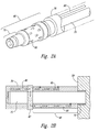
- Figures 2a and 2b generally illustrate preferred embodiments of a device for injecting a fluid adjacent to a conductor 40 and a connector 70 that are attached to a boom-type of fuel delivering device 30.
- the fuel delivering device 30 may include a fuel duct 75 for passing a fluid such as jet fuel and a second duct 80 for passing an inert gas, as represented by the arrows in Figure 2b.
- the conductor may also contain a plenum 87 for distributing inert gas from the second duct 80 to injecting ducts 85, 95.
- the conductor 40 may include a number of ducts 85 that connect the internal inert gas duct to an outer surface of the conductor 40 and are adapted to inject inert gas into the adjacent air stream.
- the conductor may also include a number of ducts 95 that connect the fuel duct 75 to an inner surface of the conductor 40 and are adapted to inject inert gas directly into the fuel duct.
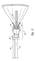
- Figure 3 generally illustrates a preferred embodiment of a device for injecting a fluid adjacent to a conductor 40' and a connector 70' that are attached to a hose and drogue type of fuel delivering device 30'.
- the fuel delivering device 30' may include a fuel duct 75' for passing a fluid such as jet fuel and a second duct 80' for passing an inert gas (represented by the arrows in Figure 3).
- the conductor may also contain a plenum 87' for connecting the second duct 80' to a number of injecting ducts 95' and distributing an inert gas to the injecting ducts adapted to inject inert gas into the fuel duct of the conductor 40'.
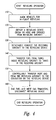
- Figure 4 is a block diagram illustrating a preferred method for a fire suppression system for reducing the risk during an in-flight refueling operation.
- the method may include aligning a refueling aircraft and a second aircraft to be refueled 110 in close proximity so a physical connection can be established.
- the method further includes deploying a device adapted to flow at least one fluid from the refueling aircraft to a conductor located on the distal end of the refueling device 120, the deployment occurring prior to or at about the same time as the aircraft alignment.
- the conductor can then be detachably coupled to a receiving location on the second aircraft 130.
- Fuel is transferred from the refueling aircraft to the second aircraft through the refueling device 140.
- an inert gas is transferred from the refueling aircraft to the conductor 150 where it is then injected from the conductor into at least one of the adjacent, external airstream and into the internal fuel duct to reduce the fuel-oxygen ratio and thus reduce the flammability of the fuel.
- fuel and inert gas transfer is stopped, and the refueling device is decoupled from the receiving aircraft 160.
- the receiving aircraft is safely maneuvered away from the refueling aircraft and may resume its normal flight operations.
Landscapes
- Engineering & Computer Science (AREA)
- Aviation & Aerospace Engineering (AREA)
- Loading And Unloading Of Fuel Tanks Or Ships (AREA)
- General Details Of Gearings (AREA)
- Emergency Protection Circuit Devices (AREA)
Applications Claiming Priority (1)
| Application Number | Priority Date | Filing Date | Title |
|---|---|---|---|
| US11/418,856 US7597288B2 (en) | 2006-05-05 | 2006-05-05 | In-flight refueling lightning protection system |
Publications (3)
| Publication Number | Publication Date |
|---|---|
| EP1852348A2 true EP1852348A2 (de) | 2007-11-07 |
| EP1852348A3 EP1852348A3 (de) | 2008-02-06 |
| EP1852348B1 EP1852348B1 (de) | 2009-07-08 |
Family
ID=38118306
Family Applications (1)
| Application Number | Title | Priority Date | Filing Date |
|---|---|---|---|
| EP07251862A Active EP1852348B1 (de) | 2006-05-05 | 2007-05-03 | Blitzschutzsystem für Betanken während des Fluges |
Country Status (5)
| Country | Link |
|---|---|
| US (1) | US7597288B2 (de) |
| EP (1) | EP1852348B1 (de) |
| AT (1) | ATE435813T1 (de) |
| DE (1) | DE602007001482D1 (de) |
| ES (1) | ES2328291T3 (de) |
Families Citing this family (8)
| Publication number | Priority date | Publication date | Assignee | Title |
|---|---|---|---|---|
| GB0908540D0 (en) * | 2009-05-19 | 2009-06-24 | Rolls Royce Plc | A gas turbine engine having a nacelle and a breather duct |
| GB0919115D0 (en) * | 2009-11-02 | 2009-12-16 | Rolls Royce Plc | Breather duct shielding |
| GB0919107D0 (en) * | 2009-11-02 | 2009-12-16 | Rolls Royce Plc | A boundary layer energiser |
| US8544508B2 (en) | 2009-12-17 | 2013-10-01 | Eads Construcciones Aeronauticas, S.A. | Telescoping tube for transferring fuel |
| EP2738097B1 (de) * | 2012-11-29 | 2015-10-07 | Airbus Defence and Space SA | Luftbetankungssystem mit digitalem Kommunikations-Subsystem |
| FR3113648B1 (fr) * | 2021-04-05 | 2025-12-12 | Jean Michel Schulz | Dispositif de vidange rapide de carburant pour les engins aériens, spatiaux, terrestres, navals ou sous-marins, utilisant un carburant cryogénique ou gazeux. |
| GB2638380A (en) * | 2023-12-13 | 2025-08-27 | Airbus Operations Ltd | Aircraft refuelling/defuelling system |
| GB2637118A (en) | 2023-12-13 | 2025-07-16 | Airbus Operations Ltd | Refuelling/defuelling an aircraft |
Family Cites Families (16)
| Publication number | Priority date | Publication date | Assignee | Title |
|---|---|---|---|---|
| US2248308A (en) * | 1938-03-07 | 1941-07-08 | Beatrice W Rice | Method and apparatus for valving inflammable fluids |
| US2634927A (en) * | 1949-01-18 | 1953-04-14 | Flight Refueling Ltd | Apparatus for transferring fuel and other liquids from one aircraft to another in flight |
| US2761701A (en) * | 1951-09-11 | 1956-09-04 | Boeing Co | Severable duct joints with plural universal connections |
| US3229446A (en) * | 1963-01-29 | 1966-01-18 | Charles R Sebastian | Combustion inhibiting method |
| US3732668A (en) * | 1971-02-24 | 1973-05-15 | Parker Hannifin Corp | Fuel tank inerting system |
| US4378920A (en) * | 1980-07-15 | 1983-04-05 | The Boeing Company | Combustibly inert air supply system and method |
| US5326052A (en) * | 1991-10-02 | 1994-07-05 | Enig Associates, Inc. | Controllable hose-and-drogue in-flight refueling system |
| FR2705082B1 (fr) * | 1993-05-12 | 1995-08-04 | Aerospatiale | Système de ravitaillement en vol. |
| US6360730B1 (en) * | 1996-03-18 | 2002-03-26 | Fuel Dynamics | Inert loading jet fuel |
| US6182714B1 (en) * | 1998-04-14 | 2001-02-06 | Irwin Ginsburgh | Fuel safety management system for storing, transporting, or transferring hydrocarbon fuel |
| US6293525B1 (en) * | 1998-06-15 | 2001-09-25 | Irwin Ginsburgh | Economical apparatus for producing improved combustion and safety-enhanced fuel |
| US6263924B1 (en) * | 1998-11-23 | 2001-07-24 | Mobil Oil Corporation | Vehicle engine system additive dispenser |
| US6463967B1 (en) * | 2000-11-17 | 2002-10-15 | The Lubrizol Corporation | System for diagnosing, maintaining and reporting the performance and safety condition of apparatus during refueling |
| FR2824045B1 (fr) * | 2001-04-26 | 2003-07-25 | Air Liquide | Procede et dispositif d'inertage d'un reservoir de carburant d'aeronef |
| US6634598B2 (en) * | 2001-11-28 | 2003-10-21 | Kenneth Susko | On-board fuel inerting system |
| US6926049B1 (en) * | 2002-08-23 | 2005-08-09 | Uav Refueling Inc. | Hose-and-drogue in-flight refueling system |
-
2006
- 2006-05-05 US US11/418,856 patent/US7597288B2/en not_active Expired - Lifetime
-
2007
- 2007-05-03 EP EP07251862A patent/EP1852348B1/de active Active
- 2007-05-03 ES ES07251862T patent/ES2328291T3/es active Active
- 2007-05-03 DE DE602007001482T patent/DE602007001482D1/de active Active
- 2007-05-03 AT AT07251862T patent/ATE435813T1/de not_active IP Right Cessation
Also Published As
| Publication number | Publication date |
|---|---|
| EP1852348B1 (de) | 2009-07-08 |
| DE602007001482D1 (de) | 2009-08-20 |
| ES2328291T3 (es) | 2009-11-11 |
| EP1852348A3 (de) | 2008-02-06 |
| ATE435813T1 (de) | 2009-07-15 |
| US20070257154A1 (en) | 2007-11-08 |
| US7597288B2 (en) | 2009-10-06 |
Similar Documents
| Publication | Publication Date | Title |
|---|---|---|
| EP1852348B1 (de) | Blitzschutzsystem für Betanken während des Fluges | |
| CN111406022B (zh) | 航天器服务装置及相关组件、系统和方法 | |
| US6869042B2 (en) | System for airborne launch of an aircraft from a larger carrier aircraft | |
| US7793887B2 (en) | Interoperable aerial refueling methods | |
| US20030136874A1 (en) | Method for safer mid-air refueling | |
| US20100024189A1 (en) | Systems and Methods for Distributing Loads from Fluid Conduits, Including Aircraft Fuel Conduits | |
| RU2085449C1 (ru) | Способ вывода воздушно-космического самолета в космос и система для его осуществления | |
| JP7259055B2 (ja) | 航空機の飛行中燃料補給のための方法およびステム | |
| US6926049B1 (en) | Hose-and-drogue in-flight refueling system | |
| US20150246731A1 (en) | Engine pylon of aircraft and aircraft | |
| EP2611691B1 (de) | Düse mit integrierter druckregelung für einen ausleger zur betankung in der luft | |
| US11273926B2 (en) | En route fluid transmitting apparatus | |
| CN1270304A (zh) | 一次性使用的运载火箭 | |
| US9403605B2 (en) | Multiple stage tractor propulsion vehicle | |
| CA2190342A1 (en) | Arrangement of outlet devices | |
| US6543715B1 (en) | Aerospace system | |
| Bjelde et al. | The Falcon 1 launch vehicle: Demonstration flights, status, manifest, and upgrade path | |
| US20070217116A1 (en) | Lightning protected aircraft telescopic refueling mast | |
| RU2085448C1 (ru) | Способ доставки грузов в космос и система для его осуществления | |
| US20250289582A1 (en) | Gas supply for aircraft applications | |
| US20250050148A1 (en) | Remote triggering of a fire extinguishing operation in a fire zone of a propulsion system | |
| US20250052200A1 (en) | Integrating an extinguisher into a "fire" zone of a turbomachine | |
| CN120135473A (zh) | 飞行器加油/放油系统 | |
| Fricke Jr | STS-51 Space Shuttle Mission Report | |
| Anderson et al. | Orbital operation study. Volume 3: Basic vehicle summaries |
Legal Events
| Date | Code | Title | Description |
|---|---|---|---|
| PUAI | Public reference made under article 153(3) epc to a published international application that has entered the european phase |
Free format text: ORIGINAL CODE: 0009012 |
|
| 17P | Request for examination filed |
Effective date: 20070514 |
|
| AK | Designated contracting states |
Kind code of ref document: A2 Designated state(s): AT BE BG CH CY CZ DE DK EE ES FI FR GB GR HU IE IS IT LI LT LU LV MC MT NL PL PT RO SE SI SK TR |
|
| AX | Request for extension of the european patent |
Extension state: AL BA HR MK YU |
|
| PUAL | Search report despatched |
Free format text: ORIGINAL CODE: 0009013 |
|
| AK | Designated contracting states |
Kind code of ref document: A3 Designated state(s): AT BE BG CH CY CZ DE DK EE ES FI FR GB GR HU IE IS IT LI LT LU LV MC MT NL PL PT RO SE SI SK TR |
|
| AX | Request for extension of the european patent |
Extension state: AL BA HR MK YU |
|
| 17Q | First examination report despatched |
Effective date: 20080807 |
|
| AKX | Designation fees paid |
Designated state(s): AT BE BG CH CY CZ DE DK EE ES FI FR GB GR HU IE IS IT LI LT LU LV MC MT NL PL PT RO SE SI SK TR |
|
| GRAP | Despatch of communication of intention to grant a patent |
Free format text: ORIGINAL CODE: EPIDOSNIGR1 |
|
| GRAS | Grant fee paid |
Free format text: ORIGINAL CODE: EPIDOSNIGR3 |
|
| GRAA | (expected) grant |
Free format text: ORIGINAL CODE: 0009210 |
|
| AK | Designated contracting states |
Kind code of ref document: B1 Designated state(s): AT BE BG CH CY CZ DE DK EE ES FI FR GB GR HU IE IS IT LI LT LU LV MC MT NL PL PT RO SE SI SK TR |
|
| REG | Reference to a national code |
Ref country code: GB Ref legal event code: FG4D |
|
| REG | Reference to a national code |
Ref country code: CH Ref legal event code: EP |
|
| REG | Reference to a national code |
Ref country code: IE Ref legal event code: FG4D |
|
| REF | Corresponds to: |
Ref document number: 602007001482 Country of ref document: DE Date of ref document: 20090820 Kind code of ref document: P |
|
| REG | Reference to a national code |
Ref country code: DE Ref legal event code: R096 Ref document number: 602007001482 Country of ref document: DE Effective date: 20090820 |
|
| REG | Reference to a national code |
Ref country code: ES Ref legal event code: FG2A Ref document number: 2328291 Country of ref document: ES Kind code of ref document: T3 |
|
| PG25 | Lapsed in a contracting state [announced via postgrant information from national office to epo] |
Ref country code: SI Free format text: LAPSE BECAUSE OF FAILURE TO SUBMIT A TRANSLATION OF THE DESCRIPTION OR TO PAY THE FEE WITHIN THE PRESCRIBED TIME-LIMIT Effective date: 20090708 |
|
| NLV1 | Nl: lapsed or annulled due to failure to fulfill the requirements of art. 29p and 29m of the patents act | ||
| PG25 | Lapsed in a contracting state [announced via postgrant information from national office to epo] |
Ref country code: FI Free format text: LAPSE BECAUSE OF FAILURE TO SUBMIT A TRANSLATION OF THE DESCRIPTION OR TO PAY THE FEE WITHIN THE PRESCRIBED TIME-LIMIT Effective date: 20090708 Ref country code: LT Free format text: LAPSE BECAUSE OF FAILURE TO SUBMIT A TRANSLATION OF THE DESCRIPTION OR TO PAY THE FEE WITHIN THE PRESCRIBED TIME-LIMIT Effective date: 20090708 Ref country code: AT Free format text: LAPSE BECAUSE OF FAILURE TO SUBMIT A TRANSLATION OF THE DESCRIPTION OR TO PAY THE FEE WITHIN THE PRESCRIBED TIME-LIMIT Effective date: 20090708 Ref country code: IS Free format text: LAPSE BECAUSE OF FAILURE TO SUBMIT A TRANSLATION OF THE DESCRIPTION OR TO PAY THE FEE WITHIN THE PRESCRIBED TIME-LIMIT Effective date: 20091108 |
|
| PG25 | Lapsed in a contracting state [announced via postgrant information from national office to epo] |
Ref country code: NL Free format text: LAPSE BECAUSE OF FAILURE TO SUBMIT A TRANSLATION OF THE DESCRIPTION OR TO PAY THE FEE WITHIN THE PRESCRIBED TIME-LIMIT Effective date: 20090708 Ref country code: PL Free format text: LAPSE BECAUSE OF FAILURE TO SUBMIT A TRANSLATION OF THE DESCRIPTION OR TO PAY THE FEE WITHIN THE PRESCRIBED TIME-LIMIT Effective date: 20090708 Ref country code: LV Free format text: LAPSE BECAUSE OF FAILURE TO SUBMIT A TRANSLATION OF THE DESCRIPTION OR TO PAY THE FEE WITHIN THE PRESCRIBED TIME-LIMIT Effective date: 20090708 |
|
| PG25 | Lapsed in a contracting state [announced via postgrant information from national office to epo] |
Ref country code: BG Free format text: LAPSE BECAUSE OF FAILURE TO SUBMIT A TRANSLATION OF THE DESCRIPTION OR TO PAY THE FEE WITHIN THE PRESCRIBED TIME-LIMIT Effective date: 20091008 Ref country code: PT Free format text: LAPSE BECAUSE OF FAILURE TO SUBMIT A TRANSLATION OF THE DESCRIPTION OR TO PAY THE FEE WITHIN THE PRESCRIBED TIME-LIMIT Effective date: 20091109 |
|
| PG25 | Lapsed in a contracting state [announced via postgrant information from national office to epo] |
Ref country code: RO Free format text: LAPSE BECAUSE OF FAILURE TO SUBMIT A TRANSLATION OF THE DESCRIPTION OR TO PAY THE FEE WITHIN THE PRESCRIBED TIME-LIMIT Effective date: 20090708 Ref country code: CZ Free format text: LAPSE BECAUSE OF FAILURE TO SUBMIT A TRANSLATION OF THE DESCRIPTION OR TO PAY THE FEE WITHIN THE PRESCRIBED TIME-LIMIT Effective date: 20090708 Ref country code: DK Free format text: LAPSE BECAUSE OF FAILURE TO SUBMIT A TRANSLATION OF THE DESCRIPTION OR TO PAY THE FEE WITHIN THE PRESCRIBED TIME-LIMIT Effective date: 20090708 Ref country code: EE Free format text: LAPSE BECAUSE OF FAILURE TO SUBMIT A TRANSLATION OF THE DESCRIPTION OR TO PAY THE FEE WITHIN THE PRESCRIBED TIME-LIMIT Effective date: 20090708 |
|
| PLBE | No opposition filed within time limit |
Free format text: ORIGINAL CODE: 0009261 |
|
| STAA | Information on the status of an ep patent application or granted ep patent |
Free format text: STATUS: NO OPPOSITION FILED WITHIN TIME LIMIT |
|
| PG25 | Lapsed in a contracting state [announced via postgrant information from national office to epo] |
Ref country code: SK Free format text: LAPSE BECAUSE OF FAILURE TO SUBMIT A TRANSLATION OF THE DESCRIPTION OR TO PAY THE FEE WITHIN THE PRESCRIBED TIME-LIMIT Effective date: 20090708 Ref country code: BE Free format text: LAPSE BECAUSE OF FAILURE TO SUBMIT A TRANSLATION OF THE DESCRIPTION OR TO PAY THE FEE WITHIN THE PRESCRIBED TIME-LIMIT Effective date: 20090708 |
|
| 26N | No opposition filed |
Effective date: 20100409 |
|
| REG | Reference to a national code |
Ref country code: DE Ref legal event code: R097 Ref document number: 602007001482 Country of ref document: DE Effective date: 20100409 |
|
| PG25 | Lapsed in a contracting state [announced via postgrant information from national office to epo] |
Ref country code: GR Free format text: LAPSE BECAUSE OF FAILURE TO SUBMIT A TRANSLATION OF THE DESCRIPTION OR TO PAY THE FEE WITHIN THE PRESCRIBED TIME-LIMIT Effective date: 20091009 |
|
| PG25 | Lapsed in a contracting state [announced via postgrant information from national office to epo] |
Ref country code: MC Free format text: LAPSE BECAUSE OF NON-PAYMENT OF DUE FEES Effective date: 20100531 |
|
| PG25 | Lapsed in a contracting state [announced via postgrant information from national office to epo] |
Ref country code: IT Free format text: LAPSE BECAUSE OF FAILURE TO SUBMIT A TRANSLATION OF THE DESCRIPTION OR TO PAY THE FEE WITHIN THE PRESCRIBED TIME-LIMIT Effective date: 20090708 |
|
| PG25 | Lapsed in a contracting state [announced via postgrant information from national office to epo] |
Ref country code: MT Free format text: LAPSE BECAUSE OF FAILURE TO SUBMIT A TRANSLATION OF THE DESCRIPTION OR TO PAY THE FEE WITHIN THE PRESCRIBED TIME-LIMIT Effective date: 20090708 Ref country code: IE Free format text: LAPSE BECAUSE OF NON-PAYMENT OF DUE FEES Effective date: 20100503 |
|
| REG | Reference to a national code |
Ref country code: CH Ref legal event code: PL |
|
| PG25 | Lapsed in a contracting state [announced via postgrant information from national office to epo] |
Ref country code: LI Free format text: LAPSE BECAUSE OF NON-PAYMENT OF DUE FEES Effective date: 20110531 Ref country code: CH Free format text: LAPSE BECAUSE OF NON-PAYMENT OF DUE FEES Effective date: 20110531 |
|
| PG25 | Lapsed in a contracting state [announced via postgrant information from national office to epo] |
Ref country code: CY Free format text: LAPSE BECAUSE OF FAILURE TO SUBMIT A TRANSLATION OF THE DESCRIPTION OR TO PAY THE FEE WITHIN THE PRESCRIBED TIME-LIMIT Effective date: 20090708 |
|
| PG25 | Lapsed in a contracting state [announced via postgrant information from national office to epo] |
Ref country code: SE Free format text: LAPSE BECAUSE OF FAILURE TO SUBMIT A TRANSLATION OF THE DESCRIPTION OR TO PAY THE FEE WITHIN THE PRESCRIBED TIME-LIMIT Effective date: 20090708 Ref country code: LU Free format text: LAPSE BECAUSE OF NON-PAYMENT OF DUE FEES Effective date: 20100503 Ref country code: HU Free format text: LAPSE BECAUSE OF FAILURE TO SUBMIT A TRANSLATION OF THE DESCRIPTION OR TO PAY THE FEE WITHIN THE PRESCRIBED TIME-LIMIT Effective date: 20100109 |
|
| PG25 | Lapsed in a contracting state [announced via postgrant information from national office to epo] |
Ref country code: TR Free format text: LAPSE BECAUSE OF FAILURE TO SUBMIT A TRANSLATION OF THE DESCRIPTION OR TO PAY THE FEE WITHIN THE PRESCRIBED TIME-LIMIT Effective date: 20090708 |
|
| REG | Reference to a national code |
Ref country code: FR Ref legal event code: PLFP Year of fee payment: 10 |
|
| REG | Reference to a national code |
Ref country code: FR Ref legal event code: PLFP Year of fee payment: 11 |
|
| REG | Reference to a national code |
Ref country code: FR Ref legal event code: PLFP Year of fee payment: 12 |
|
| P01 | Opt-out of the competence of the unified patent court (upc) registered |
Effective date: 20230516 |
|
| PGFP | Annual fee paid to national office [announced via postgrant information from national office to epo] |
Ref country code: ES Payment date: 20260601 Year of fee payment: 20 |
|
| PGFP | Annual fee paid to national office [announced via postgrant information from national office to epo] |
Ref country code: GB Payment date: 20260527 Year of fee payment: 20 |
|
| PGFP | Annual fee paid to national office [announced via postgrant information from national office to epo] |
Ref country code: DE Payment date: 20260528 Year of fee payment: 20 |
|
| PGFP | Annual fee paid to national office [announced via postgrant information from national office to epo] |
Ref country code: FR Payment date: 20260525 Year of fee payment: 20 |