EP1852214A1 - Workpiece clamping device with tool carrier - Google Patents
Workpiece clamping device with tool carrier Download PDFInfo
- Publication number
- EP1852214A1 EP1852214A1 EP07008276A EP07008276A EP1852214A1 EP 1852214 A1 EP1852214 A1 EP 1852214A1 EP 07008276 A EP07008276 A EP 07008276A EP 07008276 A EP07008276 A EP 07008276A EP 1852214 A1 EP1852214 A1 EP 1852214A1
- Authority
- EP
- European Patent Office
- Prior art keywords
- tool
- workpiece
- machining
- holding device
- clamping
- Prior art date
- Legal status (The legal status is an assumption and is not a legal conclusion. Google has not performed a legal analysis and makes no representation as to the accuracy of the status listed.)
- Granted
Links
Images


Classifications
-
- B—PERFORMING OPERATIONS; TRANSPORTING
- B23—MACHINE TOOLS; METAL-WORKING NOT OTHERWISE PROVIDED FOR
- B23Q—DETAILS, COMPONENTS, OR ACCESSORIES FOR MACHINE TOOLS, e.g. ARRANGEMENTS FOR COPYING OR CONTROLLING; MACHINE TOOLS IN GENERAL CHARACTERISED BY THE CONSTRUCTION OF PARTICULAR DETAILS OR COMPONENTS; COMBINATIONS OR ASSOCIATIONS OF METAL-WORKING MACHINES, NOT DIRECTED TO A PARTICULAR RESULT
- B23Q7/00—Arrangements for handling work specially combined with or arranged in, or specially adapted for use in connection with, machine tools, e.g. for conveying, loading, positioning, discharging, sorting
- B23Q7/14—Arrangements for handling work specially combined with or arranged in, or specially adapted for use in connection with, machine tools, e.g. for conveying, loading, positioning, discharging, sorting co-ordinated in production lines
- B23Q7/1426—Arrangements for handling work specially combined with or arranged in, or specially adapted for use in connection with, machine tools, e.g. for conveying, loading, positioning, discharging, sorting co-ordinated in production lines with work holders not rigidly fixed to the transport devices
-
- B—PERFORMING OPERATIONS; TRANSPORTING
- B23—MACHINE TOOLS; METAL-WORKING NOT OTHERWISE PROVIDED FOR
- B23B—TURNING; BORING
- B23B5/00—Turning-machines or devices specially adapted for particular work; Accessories specially adapted therefor
- B23B5/36—Turning-machines or devices specially adapted for particular work; Accessories specially adapted therefor for turning specially-shaped surfaces by making use of relative movement of the tool and work produced by geometrical mechanisms, i.e. forming-lathes
- B23B5/40—Turning-machines or devices specially adapted for particular work; Accessories specially adapted therefor for turning specially-shaped surfaces by making use of relative movement of the tool and work produced by geometrical mechanisms, i.e. forming-lathes for turning spherical surfaces inside or outside
-
- B—PERFORMING OPERATIONS; TRANSPORTING
- B23—MACHINE TOOLS; METAL-WORKING NOT OTHERWISE PROVIDED FOR
- B23Q—DETAILS, COMPONENTS, OR ACCESSORIES FOR MACHINE TOOLS, e.g. ARRANGEMENTS FOR COPYING OR CONTROLLING; MACHINE TOOLS IN GENERAL CHARACTERISED BY THE CONSTRUCTION OF PARTICULAR DETAILS OR COMPONENTS; COMBINATIONS OR ASSOCIATIONS OF METAL-WORKING MACHINES, NOT DIRECTED TO A PARTICULAR RESULT
- B23Q3/00—Devices holding, supporting, or positioning work or tools, of a kind normally removable from the machine
- B23Q3/155—Arrangements for automatic insertion or removal of tools, e.g. combined with manual handling
Definitions
- the invention relates to a device for machining, in particular machining of workpieces in machine tools.
- the invention relates to a device for processing differential housings in machining centers.
- the DE 41 42 121 A1 a tact line with individual processing stations, each having at least one machining spindle for performing a machining on a workpiece.
- the tact line is used for processing also called “differential carrier” or “differential gear housing” differential housings of motor vehicle differential gears.
- the document mentions both a workpiece transfer, in which the workpieces are clamped on pallets, as well as a so-called device-free transfer, in which the differential housings from processing station to processing station are given without a separate device on.
- the individual processing stations are each set up for specific operations.
- the tact line in the specifically designed form is only suitable for processing differential housings. If other workpieces are to be processed, extensive retooling measures are required.
- Compensating housings are hollow workpieces that are to be machined on their inner surfaces.
- the disclosed DE 41 04 474 C1 a tool that is equipped with a taper shank for attachment in a work spindle. His cutting tool is pivotally mounted on the tool body, wherein the pivoting movement is effected by an adjusting rod.
- Deviating areas can not or only with difficulty be processed.
- the DE 102 39 270 A1 discloses an apparatus for processing differential housings with a countersinking tool to be inserted into the interior of the differential housing.
- the countersink has frontally open coupling openings in the two motor-driven, axially displaceable drive mandrels can be inserted, which are rotatably inserted from opposite end faces with a coupling tip in the coupling openings.
- the device provided according to the invention also contains a tool, which is carried by the base at least when it is at rest. If necessary, it can be transferred to a work spindle of the machine tool, for example in the form of a machining center. Because the tool is on the apparatus is provided, on the machine tool (the machining center) no special in particular no unusual bambooshunt required for the machining operation. Therefore, both small and very small series as well as large series are editable. It is possible to work with mixed lots, where in a machining center completely different workpieces, such as differential housing and other machine parts, such as crankshafts are processed.
- the tool is supported on the base by a positioning device, by means of which the tool is held movably between a rest position and a working position.
- the positioning device may include a fluid-actuated or an electromotive drive device and be designed, for example, as a linear positioning device.
- the tool can in the interior of the example, designed as a hollow body workpiece, for. in the form of a differential housing and retracted.
- the holding means is preferably adapted to hold the tool in the rest position while, after having transferred the tool to the working position and e.g. is coupled to a work spindle releases. It can then return to its rest position while the tool remains in working position. As a result, the positioning device does not hinder the machining operation to be performed by the tool.
- the tool is preferably designed for machining and, for example, designed as a milling tool. It can be a face milling cutter, a curved surface milling cutter, a countersinking tool or the like. This can be both flat, arranged in the interior of a differential housing bearing surfaces as well as spherical or otherwise curved surfaces, eg as support or bearing surfaces for the planets of the differential gear can be edited.
- the tool is preferably provided with a coupling device for coupling the tool within the workpiece to a work spindle of the machine tool.
- the coupling device may be a positive fit, to which an adapter can be connected.
- the positive fit creates in particular a rotationally fixed connection between the adapter and the tool.
- the coupling device preferably provides a backlash-free fit of the tool to the adapter to ensure that the tool is guided by the work spindle during the machining of the workpiece.
- the adapter may also be adapted to support the tool on the workpiece, in particular to store. For example, it may have a non-round or round, for example. Cylindrical shaft which projects through a bore of the workpiece and is supported on the wall thereof.
- the bore may be a transverse bore or an axial bore of the differential housing.
- the diameter of the adapter shaft is matched to the diameter of the bore.
- the device also includes a counter-holding device to axially support the tool with respect to its axis of rotation.
- the counter-holding device can be held axially adjustable by a rotatably mounted spindle, which is provided on the device.
- a rotatably mounted spindle which is provided on the device.
- the device preferably has a multiplicity of fluid actuated actuators, for example for actuating holding devices, which clamp the workpiece at least during processing. Further actuators may be provided for this, the counter-holding device and the positioning device to steer for the tool.
- appropriate media such as compressed air and / or hydraulic fluid, and given and, if necessary, electrical supply line or measuring lines appropriate coupling means are preferably provided to supply the device in the machine tool with the required media and connect to external devices can.
- the machine tool 1 shows a machine tool 1 is illustrated, which is designed in the manner of a machining center. The enclosure of the working space is left out in the drawing.
- the machine tool 1 has at least one table 2, on which a device 3 can be placed, which holds the workpiece 4.
- the device 3 forms a self-contained module that can be transported together with the workpiece 4 by various processing stations. Alternatively, it is possible to leave the device 3 in the machine tool 1 and to use only the workpiece 4 for processing in the device 3.
- the device 3 is preferably placed resting in the machine tool 1.
- the table 2 may also be provided with means to move the device 3 in one or more directions.
- To the machine tool 1 further includes at least one work spindle 5, which is movable in at least one spatial direction, preferably in a plurality of spatial directions and which is adapted to drive a tool rotationally.
- the work spindle 5 is e.g. oriented horizontally. It can also be used in other spatial directions, e.g. be oriented vertically. There may also be several e.g. be provided parallel to each other working spindles, which at the same time, e.g. are each brought into engagement with a workpiece. Thus, several identical or different workpieces can be clamped and processed simultaneously on a device.
- the workpiece 4 is in the present embodiment, a differential housing 6, which belongs to a motor vehicle differential gear.
- the differential housing 6 has a number of successive surfaces to be machined, some of which are in the space enclosed by the differential housing 6 interior.
- the surfaces to be machined include axial bores 7, 8, transverse bores 9, 10 for the planetary gears and a forming surface 11 situated in the interior of the differential housing 6, the plane Has sections and spherical sections.
- the axial bores 7, 8 are arranged coaxially to a common axis of rotation 12 and arranged in short, formed as a tubular extensions 13, 14 bearing seats.
- a flange 15 is formed, which is provided with mounting holes 16.
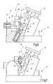
- the device 3 for processing the differential housing 6 in the machining center is shown separately and simplified in FIGS. 5 to 7.
- a base 17 in the form of a base plate, a skeleton, base frame or generally a support device.
- the base 17 is adapted to be connected to the table 2 of the machine tool 1.
- clamping means 18, 19 Figure 1 are provided for the differential housing 6, which form a clamping device 20 for tightening the differential housing 6 or any other workpiece 4 on the device 3.
- the clamping means 18, 19 are preferably bearing prisms for the tube extensions 13, 14 and associated clamping claws, which are connected to a suitable actuating device, such as hydraulic cylinders.
- one or more alignment devices 21 may be associated with the tensioning device 20 to provide the differential housing 6 with a desired rotational position and axial position.
- a pressure finger 22 illustrates that is to be actuated by means of a hydraulic cylinder 23 and axially pushes the differential housing 6 in a defined position before clamping.
- the differential housing 6 is preferably held in the device 3, as illustrated in FIGS. 5 to 7, with horizontal alignment of its transverse bores 9, 10.
- a tool storage space 24 is preferably provided below the workpiece 4. This serves to receive and temporarily store one or two or more tools. In the present embodiment, this is illustrated for only one tool 25, which is designed as a milling tool and for machining the molding surface 11 or portions thereof.
- the tool 25 can be adjusted by a positioning device 26 at least between a rest position according to FIG. 5 and a working position in which the tool 25 is in the position according to FIG. The positioning device 26 can thus move the tool 25 out of and into the workpiece 4.
- the positioning device 26 is preferably detachably connected to the tool 25 via a gripper device 27.
- the tool 25 it is possible for the tool 25 to be movably mounted, for example rotatably, on a cantilever of the positioning device 26 and to refrain from separating the tool 25 from the positioning device 26.
- the gripping device 27 preferably includes at least two jaws 28, 29, which engage in corresponding recesses 30, 31 of the tool 5 to hold this temporarily.
- the claws 28, 29 can each form latching couplings with the recesses 30, 31, by means of which the tool 25 can be connected to and uncoupled from the positioning device 26 by the claws 28, 29 moving towards or away from the tool 25 become.
- the jaws 28, 29 are preferably pivotally mounted radially outwardly, wherein they may be biased by a spring 32 radially inwardly.
- the positioning device 26 includes, for example, a hydraulic cylinder 33 with pistons displaceably mounted therein, wherein the piston rod engages with the piston Claws 28, 29 is connected.
- the positioning device 26 may further include an imprinting device 34 provided with a finger 35 coaxial with and juxtaposed with the positioning device 26. It can serve to press the tool 25 between the jaws 28, 29 to make the locking connection between the jaws 28, 29 and the tool 25.
- Figure 8 illustrates the tool 25 within the differential housing 6 in working position.
- the claws of the positioning device 26 are released from the tool 25.
- the tool 25 is formed in this embodiment as a form cutter, which is provided with a plurality of cutting plates 36, 37.
- Its tool body 38 has corresponding plate seats.
- the tool body 38 is also provided with a bore, for example a through-bore 39, which serves for connection to the work spindle 5.
- an adapter 40 is provided in the present example, which has a cylindrical neck 41, for example, which fits through an opening of the differential housing 6, for example by its transverse bore 10.
- the neck 41 is provided at its end facing the tool 25 with a coupling means 42 for non-rotatably positive connection of the adapter 40 to the tool 25.
- the coupling agent 42 is e.g. formed by a non-circular portion of the neck 41, for example, by a hexagonal section. Accordingly, the bore 39 has a suitably shaped portion 43. In addition, it may have a cylindrical portion 44 of smaller diameter, in which a cylinder extension 45 of the adapter 40 fits.
- the neck 41 may be provided with a gripping disc 46 and a taper shank 47 or other means be, which serve to connect between the adapter 40 and the work spindle 5.
- a counter-holding device 48 e.g. be provided in the form of a support pin 49 which is held on a spindle 50 ( Figure 1).
- the spindle 50 is arranged fixed or adjustable on the device 3. Preferably, it has adjusting means for axial adjustment, so that the mandrel 49 can be retracted and extended through a suitable bore of the workpiece 4.
- the spindle 50 is preferably arranged opposite the work spindle 5.
- the work spindle 5 and the spindle 50 are thus arranged in operation coaxially with a common axis of rotation 51.
- the machine tool 1 and apparatus 3 described so far work together to machine the workpiece 4, in particular the differential housing 6, as follows:
- the differential housing 6 is inserted into the device 3, which is already in the machine tool 1 or it is transferred together with the device 3 in the machine tool 1.
- the differential housing 6 is first aligned by actuation of the corresponding alignment device (s) 21 and then tensioned.
- the clamping device 20 It can be processed in the machining center first as an ordinary workpiece. But if the inner mold surface 11 are processed in this or in another similar kind of machining center 1, the tool storage device provided in the device 3 is activated. In other words, the at least one tool 25 is moved out of the tool storage space 24 into the differential housing 6.
- the positioning device 26 is driven accordingly.
- the positioning device 26 transfers the tool 25 in a position in which its bore 39 is aligned with holes of the differential housing 6, for example with its transverse bores 9, 10 or, if the processing of the axial bores 7, 8 bounding inner surfaces is desired, aligned with the axle holes 7, 8.
- a plurality of tools (not further illustrated in FIGS. 5 to 7) can be held ready in different alignment positions in order to be retracted alternatively into the interior of the differential housing 6.
- the adapter 40 was previously used.
- the adapter 40 ride with its neck 41 and the mandrel 49 through corresponding holes (9, 10) of the differential housing and take the tool 25 between each other.
- the positive connection between the coupling means 42 (non-circular portion) and the tool 25 creates a rotationally fixed coupling between the tool 25 and the work spindle 5.
- the mandrel 49 exerts an axial pressure on the tool 25 so that it is fixed between the adapter 40 and the mandrel 49 is held.
- the mandrel 49 may for example be pneumatically or hydraulically pressurized, thus exerting in each position an axial compressive force on the adapter 40 and the work spindle 50. Each axial movement of the work spindle 50 is thus followed by the tool 25. It can now be rotationally brought to the mold surface 11 in order to process it.
- the work spindle 50 is positioned so that the jaws 28, 29 can reach the tool 25.
- the positioning device 26 and the Nachdschreib noisy 34 are now operated so that the finger 35 presses from above against the tool 25.
- the jaws 28, 29 are now pushed from below over the tool 25 and engage this one.
- the push-over device 34 can be inactivated again, ie the finger 35 can be moved out of the differential housing 6.
- the tool 25 is now free and can be moved back into the tool storage space 24.
- the processing of the mold surface 11 is thus completed or can be continued with another tool otherwise held in a similar manner by this is retracted into the interior of the differential housing 6 and connected to the work spindle 5, as described above.
- a suitable for processing of differential housings 6 in machining centers 1 device 3 has a tool storage space 24, in which at least one tool 25 is held, which is suitable for processing an inner mold surface 11 of the differential housing 6.
- the tool 25 is associated with a positioning device 26, which is also part of the device 3 and with which the tool 25 can be moved into and out of the differential housing 6.
- a corresponding adapter 40 is used, which, for example, is held in the tool magazine of the machine tool 1 or of the machining center like an ordinary tool can. It is, if necessary, replaced by a tool changing device in the work spindle 5.
Abstract
Description
Die Erfindung betrifft eine Vorrichtung zur Bearbeitung, insbesondere spanenden Bearbeitung von Werkstücken in Werkzeugmaschinen. Insbesondere betrifft die Erfindung eine Vorrichtung zur Bearbeitung von Ausgleichsgehäusen in Bearbeitungszentren.The invention relates to a device for machining, in particular machining of workpieces in machine tools. In particular, the invention relates to a device for processing differential housings in machining centers.
Für die Bearbeitung von Werkstücken, auch von kompliziert geformten Werkstücken und Maschinenteilen, werden häufig Maschinen eingesetzt, die allgemein für verschiedene Bearbeitungsvorgänge eingesetzt werden können und die für verschiedene Werkstücke geeignet sind. Zur Anpassung an bestimmte Werkstücke sind dann meist spezielle Vorrichtungen und auch Werkzeuge vorgesehen, die für das spezifische Werkstück und den spezifischen Bearbeitungsvorgang eingerichtet sind.For the machining of workpieces, even of complicatedly shaped workpieces and machine parts, often machines are used, which can be used in general for various machining operations and which are suitable for different workpieces. To adapt to certain workpieces then usually special devices and tools are provided, which are set up for the specific workpiece and the specific machining operation.
Beispielsweise offenbart die
Ausgleichsgehäuse sind hohl ausgebildete Werkstücke, die an ihren Innenflächen zu bearbeiten sind. Dazu offenbart z.B. die
Mit einem solchen Werkzeug lassen sich in hohlen Werkstücken Kugelflächen bearbeiten. Davon abweichende Flächen können nicht oder nur schwierig bearbeitet werden.With such a tool, spherical surfaces can be machined in hollow workpieces. Deviating areas can not or only with difficulty be processed.
Die
Die Verwendung dieses Konzepts setzt das Vorhandensein einer Werkzeugmaschine mit zwei einander gegenüber liegend und koaxial zueinander angeordneten Arbeitsspindeln voraus.The use of this concept presupposes the presence of a machine tool with two working spindles arranged opposite one another and coaxial with each other.
Dies gilt auch im Hinblick auf die
Letztendlich handelt es sich hierbei um Spezialmaschinen, die eine Sonderanschaffung darstellen.Ultimately, these are special machines that represent a special acquisition.
Es werden jedoch zunehmend Rufe nach einer flexibleren Verwendung von angeschafften Werkzeugmaschinen laut.However, there are increasing calls for a more flexible use of purchased machine tools.
Daher ist es Aufgabe der Erfindung, eine Möglichkeit anzugeben, mit der Werkstücke, insbesondere Ausgleichsgehäuse, effizient zu fertigen sind. Außerdem war ein entsprechendes Verfahren zu schaffen.It is therefore an object of the invention to provide a way with which workpieces, in particular differential housing, are efficient to manufacture. In addition, a corresponding procedure was created.
Diese Aufgabe wird durch Schaffung der Vorrichtung mit den Merkmalen des Patentanspruchs 1 sowie des Verfahrens mit dem Merkmalen des Anspruchs 19 gelöst:This object is achieved by providing the device with the features of claim 1 and the method with the features of claim 19:
Die erfindungsgemäß vorgesehene Vorrichtung enthält außer einer Basis zur Lagerung und Spannung des Werkstücks während der Bearbeitung außerdem ein Werkzeug, das wenigstens im Ruhezustand von der Basis getragen ist. Es ist bedarfsweise an eine Arbeitsspindel der Werkzeugmaschine, beispielsweise in Form eines Bearbeitungszentrums, übergebbar. Weil das Werkzeug an der Vorrichtung vorgesehen ist, sind an der Werkzeugmaschine (dem Bearbeitungszentrum) keine besonderen insbesondere keine ungewöhnlichen Einrichtungsmaßnahmen für den Bearbeitungsvorgang erforderlich. Deshalb sind sowohl Klein- und Kleinstserien als auch Großserien bearbeitbar. Es ist möglich, mit gemischten Losen zu arbeiten, bei denen in einem Bearbeitungszentrum nacheinander ganz unterschiedliche Werkstücke, z.B. Ausgleichsgehäuse und anderweitige Maschinenteile, z.B. Kurbelwellen bearbeitet werden.In addition to a base for supporting and tensioning the workpiece during machining, the device provided according to the invention also contains a tool, which is carried by the base at least when it is at rest. If necessary, it can be transferred to a work spindle of the machine tool, for example in the form of a machining center. Because the tool is on the apparatus is provided, on the machine tool (the machining center) no special in particular no unusual Einrichtungsmaßnahmen required for the machining operation. Therefore, both small and very small series as well as large series are editable. It is possible to work with mixed lots, where in a machining center completely different workpieces, such as differential housing and other machine parts, such as crankshafts are processed.
Bei einer bevorzugten Ausführungsform ist das Werkzeug an der Basis von einer Positioniereinrichtung getragen, mittels derer das Werkzeug zwischen einer Ruheposition und einer Arbeitsposition bewegbar gehalten ist. Die Positioniereinrichtung kann eine fluidbetätigte oder eine elektromotorische Antriebseinrichtung enthalten und beispielsweise als Linearstelleinrichtung ausgebildet sein. Damit kann das Werkzeug in den Innenraum des beispielsweise als Hohlkörper ausgebildeten Werkstücks z.B. in Form eines Ausgleichsgehäuses ein- und ausgefahren werden.In a preferred embodiment, the tool is supported on the base by a positioning device, by means of which the tool is held movably between a rest position and a working position. The positioning device may include a fluid-actuated or an electromotive drive device and be designed, for example, as a linear positioning device. Thus, the tool can in the interior of the example, designed as a hollow body workpiece, for. in the form of a differential housing and retracted.
Die Halteeinrichtung ist vorzugsweise so beschaffen, dass sie das Werkzeug in Ruheposition festhält während sie das Werkzeug, nachdem es in Arbeitsposition überführt und z.B. an eine Arbeitsspindel angekoppelt ist, freigibt. Sie kann dann in ihre Ruheposition zurück fahren während das Werkzeug in Arbeitsposition bleibt. Dadurch behindert die Positioniereinrichtung den von dem Werkzeug auszuführenden Bearbeitungsvorgang nicht.The holding means is preferably adapted to hold the tool in the rest position while, after having transferred the tool to the working position and e.g. is coupled to a work spindle releases. It can then return to its rest position while the tool remains in working position. As a result, the positioning device does not hinder the machining operation to be performed by the tool.
Das Werkzeug ist vorzugsweise zur spanenden Bearbeitung eingerichtet und z.B. als Fräswerkzeug ausgebildet. Es kann sich um einen Planfräser, um einen Fräser für gekrümmte Flächen, um ein Senkwerkzeug oder dergleichen handeln. Damit können sowohl ebene, im Innenraum eines Ausgleichsgehäuses angeordnete Lagerflächen als auch sphärische oder anderweitig gekrümmte Flächen, z.B. als Stütz- oder Lagerflächen für die Planeten des Ausgleichsgetriebes bearbeitet werden.The tool is preferably designed for machining and, for example, designed as a milling tool. It can be a face milling cutter, a curved surface milling cutter, a countersinking tool or the like. This can be both flat, arranged in the interior of a differential housing bearing surfaces as well as spherical or otherwise curved surfaces, eg as support or bearing surfaces for the planets of the differential gear can be edited.
Das Werkzeug ist vorzugsweise mit einer Kupplungseinrichtung zur Ankopplung des Werkzeugs innerhalb des Werkstücks an eine Arbeitsspindel der Werkzeugmaschine versehen. Die Kupplungseinrichtung kann ein formschlüssiger Sitz sein, an den ein Adapter anschließbar ist. Der formschlüssige Sitz schafft insbesondere eine drehfeste Verbindung zwischen dem Adapter und dem Werkzeug. Außerdem schafft die Kupplungseinrichtung vorzugsweise einen spielfreien Sitz des Werkzeugs an dem Adapter, um sicherzustellen, dass das Werkzeug während der spanenden Bearbeitung des Werkstücks von der Arbeitsspindel geführt ist. Der Adapter kann außerdem dazu eingerichtet sein, das Werkzeug an dem Werkstück abzustützen, insbesondere zu lagern. Z.B. kann es einen unrunden oder auch runden, bspw. zylindrischen Schaft aufweisen, der eine Bohrung des Werkstücks durchragt und sich an deren Wand abstützt. Die Bohrung kann eine Querbohrung oder eine Achsbohrung des Ausgleichsgehäuses sein. Der Durchmesser des Adapterschafts ist dazu auf den Durchmesser der Bohrung abgestimmt.The tool is preferably provided with a coupling device for coupling the tool within the workpiece to a work spindle of the machine tool. The coupling device may be a positive fit, to which an adapter can be connected. The positive fit creates in particular a rotationally fixed connection between the adapter and the tool. In addition, the coupling device preferably provides a backlash-free fit of the tool to the adapter to ensure that the tool is guided by the work spindle during the machining of the workpiece. The adapter may also be adapted to support the tool on the workpiece, in particular to store. For example, it may have a non-round or round, for example. Cylindrical shaft which projects through a bore of the workpiece and is supported on the wall thereof. The bore may be a transverse bore or an axial bore of the differential housing. The diameter of the adapter shaft is matched to the diameter of the bore.
Vorzugsweise enthält die Vorrichtung außerdem eine Gegenhalteeinrichtung, um das Werkzeug bezüglich seiner Drehachse axial abzustützen. Die Gegenhalteeinrichtung kann durch eine drehbar gelagerte Spindel axial verstellbar gehalten sein, die an der Vorrichtung vorgesehen ist. Damit ist an der Werkzeugmaschine keine zweite Arbeitsspindel erforderlich.Preferably, the device also includes a counter-holding device to axially support the tool with respect to its axis of rotation. The counter-holding device can be held axially adjustable by a rotatably mounted spindle, which is provided on the device. Thus, no second work spindle is required on the machine tool.
Die Vorrichtung weist vorzugsweise eine Vielzahl fluidbetätigter Aktoren, beispielsweise zur Betätigung von Halteeinrichtungen auf, die das Werkstück zumindest während der Bearbeitung festklemmen. Weitere Aktoren können dazu vorgesehen sein, die Gegenhalteeinrichtung sowie die Positioniereinrichtung für das Werkzeug zu steuern. Zum An- und Abkuppeln entsprechender Medien, beispielsweise Druckluft und/oder Hydraulikfluid, sowie gegebenen- und erforderlichenfalls auch elektrischer Versorgungsleitung oder Messleitungen sind vorzugsweise entsprechende Kupplungseinrichtungen vorgesehen, um die Vorrichtung in der Werkzeugmaschine mit den geforderten Medien versorgen und an externe Einrichtungen anschließen zu können.The device preferably has a multiplicity of fluid actuated actuators, for example for actuating holding devices, which clamp the workpiece at least during processing. Further actuators may be provided for this, the counter-holding device and the positioning device to steer for the tool. For coupling and uncoupling appropriate media, such as compressed air and / or hydraulic fluid, and given and, if necessary, electrical supply line or measuring lines appropriate coupling means are preferably provided to supply the device in the machine tool with the required media and connect to external devices can.
Weitere Einzelheiten vorteilhafter Ausführungsformen der Erfindung ergeben sich aus der Zeichnung, der Beschreibung sowie Ansprüchen. Kleine Details von Ausführungsformen der Erfindung sind ebenfalls der Zeichnung zu entnehmen.Further details of advantageous embodiments of the invention will become apparent from the drawings, the description and claims. Small details of embodiments of the invention are also shown in the drawing.
In der Zeichnung ist ein Ausführungsbeispiel der Erfindung veranschaulicht. Es zeigen:
- Figur 1
- ein Bearbeitungszentrum mit einer erfindungsgemäßen Vorrichtung in schematisierter perspektivischer Darstellung,
Figur 2 bis 4- ein Ausgleichsgehäuse zur Bearbeitung auf dem Bearbeitungszentrum gemäß Figur 1 in verschiedenen perspektivischen Darstellungen,
Figur 5- eine Vorrichtung zur Aufnahme des Ausgleichsgehäuses nach
Figur 2 bis 4 zur Bearbeitung desselben in dem Bearbeitungszentrum nach Figur 1 in schematisierter Seitenansicht, Figur 6- die Vorrichtung nach
Figur 5 in teilweise geschnittener Seitenansicht mit Werkzeug in Ruheposition, Figur 7- die
Vorrichtung nach Figur 5 mit teilweise geschnittenem Werkstück und Werkzeug in Bearbeitungsposition, Figur 8- das Werkzeug und ein zugehöriger Adapter in Kupplungsstellung.
- FIG. 1
- a processing center with a device according to the invention in a schematic perspective view,
- FIGS. 2 to 4
- a differential housing for machining on the machining center according to FIG. 1 in various perspective views,
- FIG. 5
- a device for receiving the differential housing of Figure 2 to 4 for processing the same in the machining center of Figure 1 in a schematic side view,
- FIG. 6
- 5 shows the device according to FIG. 5 in a partially sectioned side view with tool in rest position, FIG.
- FIG. 7
- the device of Figure 5 with partial cut workpiece and tool in machining position,
- FIG. 8
- the tool and an associated adapter in the coupling position.
In Figur 1 ist eine Werkzeugmaschine 1 veranschaulicht, die nach Art eines Bearbeitungszentrums ausgebildet ist. Die Einhausung des Arbeitsraums ist in der Zeichnung weg gelassen. Die Werkzeugmaschine 1 weist zumindest einen Tisch 2 auf, auf dem eine Vorrichtung 3 platziert werden kann, die das Werkstück 4 hält. Die Vorrichtung 3 bildet ein in sich abgeschlossenes Modul, das mit dem Werkstück 4 gemeinsam durch verschiedene Bearbeitungsstationen transportiert werden kann. Alternativ ist es möglich, die Vorrichtung 3 in der Werkzeugmaschine 1 zu belassen und lediglich das Werkstück 4 jeweils zur Bearbeitung in die Vorrichtung 3 einzusetzen. Die Vorrichtung 3 wird in der Werkzeugmaschine 1 vorzugsweise ruhend platziert. Der Tisch 2 kann jedoch auch mit Mitteln versehen sein, um die Vorrichtung 3 in einer oder in mehreren Richtungen kontrolliert zu bewegen.1 shows a machine tool 1 is illustrated, which is designed in the manner of a machining center. The enclosure of the working space is left out in the drawing. The machine tool 1 has at least one table 2, on which a
Zu der Werkzeugmaschine 1 gehört des Weiteren zumindest eine Arbeitsspindel 5, die in zumindest einer Raumrichtung, vorzugsweise in mehreren Raumrichtungen bewegbar ist und die dazu eingerichtet ist, ein Werkzeug drehend anzutreiben. Die Arbeitsspindel 5 ist z.B. horizontal orientiert. Sie kann auch in anderen Raumrichtungen, z.B. vertikal orientiert sein. Es können auch mehrere z.B. parallel zueinander angeordnete Arbeitsspindeln vorgesehen sein, die gleichzeitig z.B. jeweils mit einem Werkstück in Eingriff gebracht werden. So können auf einer Vorrichtung mehrere gleiche oder unterschiedliche Werkstücke gespannt und gleichzeitig bearbeitet werden.To the machine tool 1 further includes at least one
Das Werkstück 4 ist im vorliegenden Ausführungsbeispiel ein Ausgleichsgehäuse 6, das zu einem Kraftfahrzeug-Differentialgetriebe gehört. Das Ausgleichsgehäuse 6 weist eine Anzahl von nacheinander zu bearbeitenden Flächen auf, von denen einige in dem von dem Ausgleichsgehäuse 6 umschlossenen Innenraum liegen. Zu den zu bearbeitenden Flächen gehören Achsbohrungen 7, 8, Querbohrungen 9, 10 für die Planetenräder und eine im Inneren des Ausgleichsgehäuses 6 gelegene Formfläche 11, die ebene Abschnitte und sphärische Abschnitte aufweist. Die Achsbohrungen 7, 8 sind koaxial zu einer gemeinsamen Drehachse 12 angeordnet und in kurzen, als Rohrfortsätze 13, 14 ausgebildeten Lagersitzen angeordnet. An einer Seite des Ausgleichsgehäuses 6 ist ein Flansch 15 ausgebildet, der mit Befestigungsbohrungen 16 versehen ist.The
Die Vorrichtung 3 zur Bearbeitung des Ausgleichsgehäuses 6 in dem Bearbeitungszentrum (Werkzeugmaschine 1) ist in den Figuren 5 bis 7 gesondert und vereinfacht veranschaulicht. Zu der Vorrichtung 3 gehört eine Basis 17 in Form einer Grundplatte, eines Grundgerüsts, Grundgestells oder allgemein einer Trägervorrichtung. Die Basis 17 ist darauf eingerichtet, mit dem Tisch 2 der Werkzeugmaschine 1 verbunden zu werden. An der Basis 17 sind Spannmittel 18, 19 (Figur 1) für das Ausgleichsgehäuse 6 vorgesehen, die eine Spanneinrichtung 20 zum Festspannen des Ausgleichsgehäuses 6 oder eines sonstigen Werkstücks 4 an der Vorrichtung 3 bilden. Die Spannmittel 18, 19 sind vorzugsweise Lagerprismen für die Rohrfortsätze 13, 14 sowie zugeordnete Spannpratzen, die mit einer geeigneten Betätigungseinrichtung, wie beispielsweise Hydraulikzylindern, verbunden sind. Zusätzlich können zu der Spanneinrichtung 20 ein oder mehrere Ausrichteinrichtungen 21 gehören, um dem Ausgleichsgehäuse 6 eine gewünschte Drehposition und Axialposition zu erteilen. In Figur 6 ist stellvertretend für weitere, nicht veranschaulichte Ausrichteinrichtungen als Ausrichteinrichtung 21 ein Druckfinger 22 veranschaulicht, der mittels eines Hydraulikzylinders 23 zu betätigen ist und der das Ausgleichsgehäuse 6 vor dem Festspannen axial in eine definierte Position schiebt.The
Das Ausgleichsgehäuse 6 wird in der Vorrichtung 3 vorzugsweise, wie in den Figuren 5 bis 7 veranschaulicht, mit horizontaler Ausrichtung seiner Querbohrungen 9, 10 gehalten. In dem Ausgleichsgehäuse 6 vorgesehene größere Fensterausschnitte weisen somit vertikal nach oben und nach unten während die Achsbohrungen 7, 8 ebenfalls horizontal orientiert sind.The
An der Basis 17 ist vorzugsweise unterhalb des Werkstücks 4 ein Werkzeugspeicherraum 24 vorgesehen. Dieser dient zur Aufnahme und Zwischenspeicherung von ein oder zwei oder mehreren Werkzeugen. Im vorliegenden Ausführungsbeispiel ist dies für lediglich ein Werkzeug 25 veranschaulicht, das als Fräswerkzeug ausgebildet ist und zur Bearbeitung der Formfläche 11 oder von Abschnitten derselben dient. Das Werkzeug 25 ist von einer Positioniereinrichtung 26 zumindest zwischen einer Ruheposition gemäß Figur 5 und einer Arbeitsposition verstellbar, in der das Werkzeug 25 in der Position gemäß Figur 7 steht. Die Positioniereinrichtung 26 kann das Werkzeug 25 somit aus dem Werkstück 4 heraus und in dieses hinein bewegen. Die Positioniereinrichtung 26 ist mit dem Werkzeug 25 vorzugsweise lösbar über eine Greifereinrichtung 27 verbunden. Alternativ ist es möglich, das Werkzeug 25 an einem Ausleger der Positioniereinrichtung 26 beweglich, beispielsweise drehbar zu lagern und darauf zu verzichten, das Werkzeug 25 von der Positioniereinrichtung 26 zu trennen.At the
Die Greifeinrichtung 27 enthält vorzugsweise wenigstens zwei Klauen 28, 29, die in entsprechende Ausnehmungen 30, 31 des Werkzeugs 5 fassen, um dieses temporär zu halten. Die Klauen 28, 29 können mit den Ausnehmungen 30, 31 jeweils Rastkupplungen bilden, durch die das Werkzeug 25 an die Positioniereinrichtung 26 an- und von dieser abgekuppelt werden kann, indem die Klauen 28, 29 auf das Werkzeug 25 zu oder von diesem weg bewegt werden. Die Klauen 28, 29 sind vorzugsweise radial nach außen schwenkbar gelagert, wobei sie durch eine Feder 32 radial nach innen vorgespannt sein können.The gripping device 27 preferably includes at least two
Zu der Positioniereinrichtung 26 gehört, wie in Figur 6 dargestellt, beispielsweise ein Hydraulikzylinder 33 mit darin verschiebbar gelagerten Kolben, wobei die Kolbenstange mit den Klauen 28, 29 verbunden ist.As shown in FIG. 6, the
Zu der Positioniereinrichtung 26 kann außerdem eine Nachdrückeinrichtung 34 gehören, die mit einem Finger 35 versehen ist, der koaxial zu der Positioniereinrichtung 26 und dieser gegenüber liegend angeordnet ist. Er kann dazu dienen, das Werkzeug 25 zwischen die Klauen 28, 29 zu pressen, um die Rastverbindung zwischen den Klauen 28, 29 und dem Werkzeug 25 herzustellen.The
Figur 8 veranschaulicht das Werkzeug 25 innerhalb des Ausgleichsgehäuses 6 in Arbeitsposition. Die Klauen der Positioniereinrichtung 26 sind von dem Werkzeug 25 gelöst. Das Werkzeug 25 ist in diesem Ausführungsbeispiel als Formfräser ausgebildet, der mit mehreren Schneidplatten 36, 37 versehen ist. Sein Werkzeugkörper 38 weist dazu entsprechende Plattensitze auf. Wie in Figur 8 veranschaulicht, ist der Werkzeugkörper 38 außerdem mit einer Bohrung, beispielsweise einer Durchgangsbohrung 39 versehen, die zum Anschluss an die Arbeitsspindel 5 dient. Dazu ist im vorliegenden Beispiel ein Adapter 40 vorgesehen, der einen beispielsweise zylindrischen Hals 41 aufweist, der durch eine Öffnung des Ausgleichsgehäuses 6, beispielsweise durch seine Querbohrung 10 passt. Der Hals 41 ist an seinem dem Werkzeug 25 zugewandten Ende mit einem Kupplungsmittel 42 zum drehfesten formschlüssigen Verbinden des Adapters 40 mit dem Werkzeug 25 versehen. Das Kupplungsmittel 42 wird z.B. durch einen unrunden Abschnitt des Halses 41 beispielsweise durch einen Sechskantabschnitt gebildet. Entsprechend weist die Bohrung 39 einen dazu passend geformten Abschnitt 43 auf. Außerdem kann sie einen zylindrischen Abschnitt 44 geringeren Durchmessers aufweisen, in die ein Zylinderfortsatz 45 des Adapters 40 passt.Figure 8 illustrates the
An dem anderen Ende kann der Hals 41 mit einer Greifscheibe 46 und einem Steilkegelschaft 47 oder anderen Mitteln versehen sein, die zur Verbindung zwischen dem Adapter 40 und der Arbeitsspindel 5 dienen.At the other end, the
Zur Abstützung des Werkzeugs 25 kann außerdem eine Gegenhalteeinrichtung 48 z.B. in Form eines Stützdorns 49 vorgesehen sein, der an einer Spindel 50 (Figur 1) gehalten ist. Die Spindel 50 ist an der Vorrichtung 3 ortsfest oder verstellbar angeordnet. Vorzugsweise weist sie Stellmittel zur Axialverstellung auf, so dass der Dorn 49 durch eine geeignete Bohrung des Werkstücks 4 ein- und ausgefahren werden kann. Die Spindel 50 ist vorzugsweise der Arbeitsspindel 5 gegenüber liegend angeordnet. Die Arbeitsspindel 5 und die Spindel 50 sind somit in Betrieb koaxial zu einer gemeinsamen Drehachse 51 angeordnet.For supporting the
Die insoweit beschriebene Werkzeugmaschine 1 und Vorrichtung 3 arbeiten zur Bearbeitung des Werkstücks 4, insbesondere des Ausgleichsgehäuses 6, wie folgt zusammen:The machine tool 1 and
Das Ausgleichsgehäuse 6 wird in die Vorrichtung 3 eingesetzt, die sich bereits in der Werkzeugmaschine 1 befindet oder es wird zusammen mit der Vorrichtung 3 in die Werkzeugmaschine 1 überführt. In der Vorrichtung 3 wird das Ausgleichsgehäuse 6 durch Betätigung der entsprechenden Ausrichteinrichtung(en) 21 zunächst ausgerichtet und dann gespannt. Dazu dient die Spanneinrichtung 20. Es kann in dem Bearbeitungszentrum zunächst wie ein gewöhnliches Werkstück bearbeitet werden. Soll aber die innere Formfläche 11 in diesem oder in einem anderen ähnlich gearteten Bearbeitungszentrum 1 bearbeitet werden, wird die in der Vorrichtung 3 vorgesehene Werkzeugspeichereinrichtung aktiviert. Mit anderen Worten, das zumindest eine Werkzeug 25 wird aus dem Werkzeugspeicherraum 24 in das Ausgleichsgehäuse 6 bewegt. Dazu wird die Positioniereinrichtung 26 entsprechend angesteuert. Die Positioniereinrichtung 26 überführt das Werkzeug 25 dabei in eine Position, in der seine Bohrung 39 mit Bohrungen des Ausgleichsgehäuses 6 fluchtet, beispielsweise mit seinen Querbohrungen 9, 10 oder, falls die Bearbeitung der die Achsbohrungen 7, 8 umgrenzenden Innenflächen gewünscht ist, mit den Achsbohrungen 7, 8 fluchtet. Es können dazu mehrere in den Figuren 5 bis 7 nicht weiter veranschaulichte Werkzeuge in unterschiedlichen Ausrichtpositionen bereit gehalten werden, um alternativ in den Innenraum des Ausgleichsgehäuses 6 eingefahren zu werden.The
Ist das Werkzeug 25 in der in Figur 7 veranschaulichten Arbeitsposition angekommen, fahren die Arbeitsspindel 5 und die Spindel 50 axial aufeinander zu. In die Arbeitsspindel 5 wurde zuvor der Adapter 40 eingesetzt. Damit fahren der Adapter 40 mit seinem Hals 41 und der Stützdorn 49 durch entsprechende Bohrungen (9, 10) des Ausgleichsgehäuses und nehmen das Werkzeug 25 zwischen einander auf. Durch den Formschluss zwischen dem Kupplungsmittel 42 (unrunder Abschnitt) und dem Werkzeug 25 entsteht eine drehfeste Kupplung zwischen dem Werkzeug 25 und der Arbeitsspindel 5. Der Stützdorn 49 übt einen axialen Druck auf das Werkzeug 25 aus, so dass es fest zwischen dem Adapter 40 und dem Stützdorn 49 gehalten ist.When the
Der Stützdorn 49 kann beispielsweise pneumatisch oder auch hydraulisch mit Druck beaufschlagt sein, womit er in jeder Position eine axiale Druckkraft auf den Adapter 40 und die Arbeitsspindel 50 ausübt. Jede Axialbewegung der Arbeitsspindel 50 wird somit von dem Werkzeug 25 nachvollzogen. Es kann nun drehend an die Formfläche 11 herangeführt werden, um diese zu bearbeiten.The
Ist der Bearbeitungsvorgang beendet, wird die Arbeitsspindel 50 so positioniert, dass die Klauen 28, 29 das Werkzeug 25 erreichen können. Die Positioniereinrichtung 26 und die Nachdrückeinrichtung 34 werden nun so betätigt, dass der Finger 35 von oben gegen das Werkzeug 25 drückt. Die Klauen 28, 29 werden nun von unten her über das Werkzeug 25 geschoben und rasten an diesem ein. Ist dies geschehen, kann die Nachdrückeinrichtung 34 wieder inaktiviert, d.h. der Finger 35 aus dem Ausgleichsgehäuse 6 heraus gefahren werden. Gleiches gilt für den Adapter 40 und den Stützdorn 49. Das Werkzeug 25 ist nun frei und kann in den Werkzeugspeicherraum 24 zurück gefahren werden. Die Bearbeitung der Formfläche 11 ist damit beendet oder kann mit einem anderen anderweitig gehaltenen Werkzeug auf ähnliche Weise fortgesetzt werden, indem dieses in den Innenraum des Ausgleichsgehäuses 6 eingefahren und mit der Arbeitsspindel 5 verbunden wird, wie vorstehend beschrieben.When the machining operation is completed, the
Bei Erreichen des Standzeitendes kann das Werkzeug 25 zusammen mit dem Adapter 40 in das Werkzeugmagazin transportiert werden. Ein neues Werkzeug 25 kann nun mittels eines weiteren Adapters 40 aus dem Werkzeugmagazin zurück in die Vorrichtung transportiert werden. Der Ablauf zum Ankoppeln des Werkzeugs 25 an den Adapter 40 erfolgt dabei in gleicher Weise wie bei der Bearbeitung des Werkstücks. Allerdings ist die Vorrichtung leer, d.h. es befindet sich kein Werkstück in ihr. Auf diese Weise kann ein Werkzeug gegen ein baugleiches Werkzeug oder ein anderes Werkzeug ausgetauscht werden.Upon reaching the end of
Eine zur Bearbeitung von Ausgleichsgehäusen 6 in Bearbeitungszentren 1 geeignete Vorrichtung 3 weist einen Werkzeugspeicherraum 24 auf, in dem zumindest ein Werkzeug 25 gehalten ist, das zur Bearbeitung einer inneren Formfläche 11 des Ausgleichsgehäuses 6 geeignet ist. Dem Werkzeug 25 ist eine Positioniereinrichtung 26 zugeordnet, die ebenfalls Teil der Vorrichtung 3 ist und mit dem das Werkzeug 25 in das Ausgleichsgehäuse 6 hinein und aus diesem heraus gefahren werden kann. Zur Herstellung einer drehfesten Verbindung zwischen dem Werkzeug 25 und einer Bearbeitungsspindel 5 der Werkzeugmaschine 1 dient ein entsprechender Adapter 40, der beispielsweise in dem Werkzeugmagazin der Werkzeugmaschine 1 bzw. des Bearbeitungszentrums wie ein gewöhnliches Werkzeug vorgehalten werden kann. Er wird bedarfsweise mittels einer Werkzeugwechseleinrichtung in die Arbeitsspindel 5 eingewechselt.A suitable for processing of
Claims (19)
Priority Applications (1)
| Application Number | Priority Date | Filing Date | Title |
|---|---|---|---|
| PL07008276T PL1852214T3 (en) | 2006-05-05 | 2007-04-24 | Workpiece clamping device with tool carrier |
Applications Claiming Priority (1)
| Application Number | Priority Date | Filing Date | Title |
|---|---|---|---|
| DE102006020895A DE102006020895A1 (en) | 2006-05-05 | 2006-05-05 | Workpiece clamping device with tool carrier |
Publications (2)
| Publication Number | Publication Date |
|---|---|
| EP1852214A1 true EP1852214A1 (en) | 2007-11-07 |
| EP1852214B1 EP1852214B1 (en) | 2008-11-12 |
Family
ID=38330704
Family Applications (1)
| Application Number | Title | Priority Date | Filing Date |
|---|---|---|---|
| EP07008276A Active EP1852214B1 (en) | 2006-05-05 | 2007-04-24 | Workpiece clamping device with tool carrier |
Country Status (5)
| Country | Link |
|---|---|
| EP (1) | EP1852214B1 (en) |
| AT (1) | ATE413942T1 (en) |
| DE (2) | DE102006020895A1 (en) |
| ES (1) | ES2314956T3 (en) |
| PL (1) | PL1852214T3 (en) |
Cited By (2)
| Publication number | Priority date | Publication date | Assignee | Title |
|---|---|---|---|---|
| CN101456131B (en) * | 2007-12-10 | 2010-06-16 | 河南森源电气股份有限公司 | High-pressure rotary isolating-switch earth-contact milling clamp |
| EP3718666A4 (en) * | 2017-12-01 | 2021-07-07 | Haru Technique Laboratory Inc. | Cutting tool for machining differential cases, differential case machining device, and differential case machining method |
Families Citing this family (1)
| Publication number | Priority date | Publication date | Assignee | Title |
|---|---|---|---|---|
| DE102017125298A1 (en) | 2017-10-27 | 2019-05-02 | Gebr. Heller Maschinenfabrik Gmbh | Method for setting up and operating a machine tool |
Citations (2)
| Publication number | Priority date | Publication date | Assignee | Title |
|---|---|---|---|---|
| DE3243335A1 (en) * | 1982-11-19 | 1984-05-24 | Deutsche Industrieanlagen GmbH, 1000 Berlin | Flexible manufacturing cell |
| DE3707318A1 (en) * | 1987-03-07 | 1988-09-15 | Scharmann Gmbh & Co | Flexible production apparatus having a plurality of axis-parallel machine tools located next to one another |
Family Cites Families (5)
| Publication number | Priority date | Publication date | Assignee | Title |
|---|---|---|---|---|
| DE4104474C1 (en) * | 1991-02-14 | 1992-04-02 | Cross Europa-Werk Gmbh, 7317 Wendlingen, De | |
| DE4142121A1 (en) * | 1991-12-20 | 1993-06-24 | Giddings & Lewis Gmbh | Transfer line for machining differential housings - has workpiece located during machining in V-blocks which are turned through 90 deg. with workpiece to preserve machining datum |
| DE19716491C2 (en) * | 1997-04-19 | 1999-07-29 | Chiron Werke Gmbh | Machine tool for machining workpiece cavities |
| DE10239270B4 (en) * | 2002-08-22 | 2013-10-24 | Komet Group Gmbh | Method and device for internal machining of housings |
| DE10307977C5 (en) * | 2003-02-24 | 2012-04-05 | Emag Holding Gmbh | Method and device for processing differential housings |
-
2006
- 2006-05-05 DE DE102006020895A patent/DE102006020895A1/en not_active Withdrawn
-
2007
- 2007-04-24 AT AT07008276T patent/ATE413942T1/en not_active IP Right Cessation
- 2007-04-24 ES ES07008276T patent/ES2314956T3/en active Active
- 2007-04-24 PL PL07008276T patent/PL1852214T3/en unknown
- 2007-04-24 DE DE502007000229T patent/DE502007000229D1/en active Active
- 2007-04-24 EP EP07008276A patent/EP1852214B1/en active Active
Patent Citations (2)
| Publication number | Priority date | Publication date | Assignee | Title |
|---|---|---|---|---|
| DE3243335A1 (en) * | 1982-11-19 | 1984-05-24 | Deutsche Industrieanlagen GmbH, 1000 Berlin | Flexible manufacturing cell |
| DE3707318A1 (en) * | 1987-03-07 | 1988-09-15 | Scharmann Gmbh & Co | Flexible production apparatus having a plurality of axis-parallel machine tools located next to one another |
Cited By (3)
| Publication number | Priority date | Publication date | Assignee | Title |
|---|---|---|---|---|
| CN101456131B (en) * | 2007-12-10 | 2010-06-16 | 河南森源电气股份有限公司 | High-pressure rotary isolating-switch earth-contact milling clamp |
| EP3718666A4 (en) * | 2017-12-01 | 2021-07-07 | Haru Technique Laboratory Inc. | Cutting tool for machining differential cases, differential case machining device, and differential case machining method |
| US11278966B2 (en) | 2017-12-01 | 2022-03-22 | Haru Technique Laboratory Inc. | Cutting tool for machining differential case, machining apparatus for differential case and machining method for differential case |
Also Published As
| Publication number | Publication date |
|---|---|
| ATE413942T1 (en) | 2008-11-15 |
| EP1852214B1 (en) | 2008-11-12 |
| PL1852214T3 (en) | 2009-04-30 |
| ES2314956T3 (en) | 2009-03-16 |
| DE502007000229D1 (en) | 2008-12-24 |
| DE102006020895A1 (en) | 2007-11-08 |
Similar Documents
| Publication | Publication Date | Title |
|---|---|---|
| DE10029749C2 (en) | Device and method for loading and / or removing workpieces on a machine tool | |
| EP1874496B1 (en) | Clamping apparatus | |
| EP1260307B1 (en) | Machine tool and method of working an elongated workpiece | |
| DE1477578B2 (en) | NUMERICALLY CONTROLLED MACHINE TOOL | |
| WO2014183871A1 (en) | Material-removing machine tool, tool set and method for producing a cylinder having a blind and/or stepped bore | |
| DE2230144C3 (en) | Tool support with a chisel slide that can be moved vertically therein with a tool changer assigned to the chisel slide | |
| DE102012209077B4 (en) | Clamping device for clamping a rod-like workpiece and machine tool so | |
| EP3600798A1 (en) | Gripping and positioning assembly for transporting a holding device between different positions | |
| DE3735858C2 (en) | ||
| EP0594103B1 (en) | Broaching machine for inner surfaces, especially vertical broaching machine | |
| EP1175278A1 (en) | Machine tool with manipulator | |
| EP1852214B1 (en) | Workpiece clamping device with tool carrier | |
| DE3245850C2 (en) | ||
| EP1884303B1 (en) | Method for centring workpieces and device for performing such a method | |
| EP0480191A2 (en) | Equipment for machining bars | |
| DE10135233A1 (en) | Circular machine for provision of fracture separation points in components, e.g. for production of connecting rods, has stationary inner work station and outer work stations in circulating section | |
| CH697293B1 (en) | Lathe, especially multi-spindle automatics. | |
| EP1056556B1 (en) | Flanging device with pressing and clamping elements | |
| EP3431223B1 (en) | Method for the preparation of workpieces and machine tool for carrying out the method | |
| DE19936502C1 (en) | Arrangement for pivotable workpiece delivery into machine tool working region has drive spindle connected to holder for fixing drive element with attached rotatable workpiece holders | |
| WO2023247056A1 (en) | Method and apparatus for positioning a workpiece between two vices | |
| DE4228708A1 (en) | Machining centre with workpiece bar feeder - has rotary table with chuck to index bar during working cycle | |
| DE2616459C2 (en) | ||
| DE10063154B4 (en) | Forging press with adjusting device on the die side | |
| EP1218124B1 (en) | Device for forming longitudinal elements |
Legal Events
| Date | Code | Title | Description |
|---|---|---|---|
| PUAI | Public reference made under article 153(3) epc to a published international application that has entered the european phase |
Free format text: ORIGINAL CODE: 0009012 |
|
| AK | Designated contracting states |
Kind code of ref document: A1 Designated state(s): AT BE BG CH CY CZ DE DK EE ES FI FR GB GR HU IE IS IT LI LT LU LV MC MT NL PL PT RO SE SI SK TR |
|
| AX | Request for extension of the european patent |
Extension state: AL BA HR MK YU |
|
| 17P | Request for examination filed |
Effective date: 20080311 |
|
| GRAP | Despatch of communication of intention to grant a patent |
Free format text: ORIGINAL CODE: EPIDOSNIGR1 |
|
| AKX | Designation fees paid |
Designated state(s): AT BE BG CH CY CZ DE DK EE ES FI FR GB GR HU IE IS IT LI LT LU LV MC MT NL PL PT RO SE SI SK TR |
|
| GRAS | Grant fee paid |
Free format text: ORIGINAL CODE: EPIDOSNIGR3 |
|
| GRAA | (expected) grant |
Free format text: ORIGINAL CODE: 0009210 |
|
| AK | Designated contracting states |
Kind code of ref document: B1 Designated state(s): AT BE BG CH CY CZ DE DK EE ES FI FR GB GR HU IE IS IT LI LT LU LV MC MT NL PL PT RO SE SI SK TR |
|
| REG | Reference to a national code |
Ref country code: GB Ref legal event code: FG4D Free format text: NOT ENGLISH |
|
| REG | Reference to a national code |
Ref country code: CH Ref legal event code: EP |
|
| REG | Reference to a national code |
Ref country code: IE Ref legal event code: FG4D Free format text: LANGUAGE OF EP DOCUMENT: GERMAN |
|
| REF | Corresponds to: |
Ref document number: 502007000229 Country of ref document: DE Date of ref document: 20081224 Kind code of ref document: P |
|
| REG | Reference to a national code |
Ref country code: RO Ref legal event code: EPE |
|
| REG | Reference to a national code |
Ref country code: SE Ref legal event code: TRGR |
|
| REG | Reference to a national code |
Ref country code: ES Ref legal event code: FG2A Ref document number: 2314956 Country of ref document: ES Kind code of ref document: T3 |
|
| LTIE | Lt: invalidation of european patent or patent extension |
Effective date: 20081112 |
|
| PG25 | Lapsed in a contracting state [announced via postgrant information from national office to epo] |
Ref country code: LT Free format text: LAPSE BECAUSE OF FAILURE TO SUBMIT A TRANSLATION OF THE DESCRIPTION OR TO PAY THE FEE WITHIN THE PRESCRIBED TIME-LIMIT Effective date: 20081112 |
|
| REG | Reference to a national code |
Ref country code: PL Ref legal event code: T3 |
|
| NLV1 | Nl: lapsed or annulled due to failure to fulfill the requirements of art. 29p and 29m of the patents act | ||
| PG25 | Lapsed in a contracting state [announced via postgrant information from national office to epo] |
Ref country code: IS Free format text: LAPSE BECAUSE OF FAILURE TO SUBMIT A TRANSLATION OF THE DESCRIPTION OR TO PAY THE FEE WITHIN THE PRESCRIBED TIME-LIMIT Effective date: 20090312 Ref country code: LV Free format text: LAPSE BECAUSE OF FAILURE TO SUBMIT A TRANSLATION OF THE DESCRIPTION OR TO PAY THE FEE WITHIN THE PRESCRIBED TIME-LIMIT Effective date: 20081112 Ref country code: SI Free format text: LAPSE BECAUSE OF FAILURE TO SUBMIT A TRANSLATION OF THE DESCRIPTION OR TO PAY THE FEE WITHIN THE PRESCRIBED TIME-LIMIT Effective date: 20081112 Ref country code: NL Free format text: LAPSE BECAUSE OF FAILURE TO SUBMIT A TRANSLATION OF THE DESCRIPTION OR TO PAY THE FEE WITHIN THE PRESCRIBED TIME-LIMIT Effective date: 20081112 Ref country code: FI Free format text: LAPSE BECAUSE OF FAILURE TO SUBMIT A TRANSLATION OF THE DESCRIPTION OR TO PAY THE FEE WITHIN THE PRESCRIBED TIME-LIMIT Effective date: 20081112 |
|
| REG | Reference to a national code |
Ref country code: HU Ref legal event code: AG4A Ref document number: E005033 Country of ref document: HU |
|
| REG | Reference to a national code |
Ref country code: IE Ref legal event code: FD4D |
|
| PG25 | Lapsed in a contracting state [announced via postgrant information from national office to epo] |
Ref country code: EE Free format text: LAPSE BECAUSE OF FAILURE TO SUBMIT A TRANSLATION OF THE DESCRIPTION OR TO PAY THE FEE WITHIN THE PRESCRIBED TIME-LIMIT Effective date: 20081112 Ref country code: DK Free format text: LAPSE BECAUSE OF FAILURE TO SUBMIT A TRANSLATION OF THE DESCRIPTION OR TO PAY THE FEE WITHIN THE PRESCRIBED TIME-LIMIT Effective date: 20081112 Ref country code: IE Free format text: LAPSE BECAUSE OF FAILURE TO SUBMIT A TRANSLATION OF THE DESCRIPTION OR TO PAY THE FEE WITHIN THE PRESCRIBED TIME-LIMIT Effective date: 20081112 Ref country code: BG Free format text: LAPSE BECAUSE OF FAILURE TO SUBMIT A TRANSLATION OF THE DESCRIPTION OR TO PAY THE FEE WITHIN THE PRESCRIBED TIME-LIMIT Effective date: 20090212 |
|
| PG25 | Lapsed in a contracting state [announced via postgrant information from national office to epo] |
Ref country code: CZ Free format text: LAPSE BECAUSE OF FAILURE TO SUBMIT A TRANSLATION OF THE DESCRIPTION OR TO PAY THE FEE WITHIN THE PRESCRIBED TIME-LIMIT Effective date: 20081112 Ref country code: PT Free format text: LAPSE BECAUSE OF FAILURE TO SUBMIT A TRANSLATION OF THE DESCRIPTION OR TO PAY THE FEE WITHIN THE PRESCRIBED TIME-LIMIT Effective date: 20090413 |
|
| PLBE | No opposition filed within time limit |
Free format text: ORIGINAL CODE: 0009261 |
|
| STAA | Information on the status of an ep patent application or granted ep patent |
Free format text: STATUS: NO OPPOSITION FILED WITHIN TIME LIMIT |
|
| PG25 | Lapsed in a contracting state [announced via postgrant information from national office to epo] |
Ref country code: SK Free format text: LAPSE BECAUSE OF FAILURE TO SUBMIT A TRANSLATION OF THE DESCRIPTION OR TO PAY THE FEE WITHIN THE PRESCRIBED TIME-LIMIT Effective date: 20081112 |
|
| 26N | No opposition filed |
Effective date: 20090813 |
|
| BERE | Be: lapsed |
Owner name: GEBR. HELLER MASCHINENFABRIK G.M.B.H. Effective date: 20090430 |
|
| PG25 | Lapsed in a contracting state [announced via postgrant information from national office to epo] |
Ref country code: MC Free format text: LAPSE BECAUSE OF NON-PAYMENT OF DUE FEES Effective date: 20090430 |
|
| PG25 | Lapsed in a contracting state [announced via postgrant information from national office to epo] |
Ref country code: BE Free format text: LAPSE BECAUSE OF NON-PAYMENT OF DUE FEES Effective date: 20090430 |
|
| PGFP | Annual fee paid to national office [announced via postgrant information from national office to epo] |
Ref country code: ES Payment date: 20100426 Year of fee payment: 4 Ref country code: FR Payment date: 20100506 Year of fee payment: 4 Ref country code: HU Payment date: 20100506 Year of fee payment: 4 Ref country code: RO Payment date: 20100329 Year of fee payment: 4 |
|
| PG25 | Lapsed in a contracting state [announced via postgrant information from national office to epo] |
Ref country code: AT Free format text: LAPSE BECAUSE OF NON-PAYMENT OF DUE FEES Effective date: 20090424 |
|
| PGFP | Annual fee paid to national office [announced via postgrant information from national office to epo] |
Ref country code: DE Payment date: 20100430 Year of fee payment: 4 Ref country code: PL Payment date: 20100326 Year of fee payment: 4 |
|
| PG25 | Lapsed in a contracting state [announced via postgrant information from national office to epo] |
Ref country code: GR Free format text: LAPSE BECAUSE OF FAILURE TO SUBMIT A TRANSLATION OF THE DESCRIPTION OR TO PAY THE FEE WITHIN THE PRESCRIBED TIME-LIMIT Effective date: 20090213 |
|
| PGFP | Annual fee paid to national office [announced via postgrant information from national office to epo] |
Ref country code: SE Payment date: 20100415 Year of fee payment: 4 |
|
| PG25 | Lapsed in a contracting state [announced via postgrant information from national office to epo] |
Ref country code: LU Free format text: LAPSE BECAUSE OF NON-PAYMENT OF DUE FEES Effective date: 20090424 |
|
| PG25 | Lapsed in a contracting state [announced via postgrant information from national office to epo] |
Ref country code: TR Free format text: LAPSE BECAUSE OF FAILURE TO SUBMIT A TRANSLATION OF THE DESCRIPTION OR TO PAY THE FEE WITHIN THE PRESCRIBED TIME-LIMIT Effective date: 20081112 |
|
| PG25 | Lapsed in a contracting state [announced via postgrant information from national office to epo] |
Ref country code: CY Free format text: LAPSE BECAUSE OF FAILURE TO SUBMIT A TRANSLATION OF THE DESCRIPTION OR TO PAY THE FEE WITHIN THE PRESCRIBED TIME-LIMIT Effective date: 20081112 |
|
| REG | Reference to a national code |
Ref country code: SE Ref legal event code: EUG |
|
| REG | Reference to a national code |
Ref country code: CH Ref legal event code: PL |
|
| GBPC | Gb: european patent ceased through non-payment of renewal fee |
Effective date: 20110424 |
|
| PGFP | Annual fee paid to national office [announced via postgrant information from national office to epo] |
Ref country code: IT Payment date: 20100430 Year of fee payment: 4 |
|
| REG | Reference to a national code |
Ref country code: FR Ref legal event code: ST Effective date: 20111230 |
|
| PG25 | Lapsed in a contracting state [announced via postgrant information from national office to epo] |
Ref country code: HU Free format text: LAPSE BECAUSE OF NON-PAYMENT OF DUE FEES Effective date: 20110425 Ref country code: DE Free format text: LAPSE BECAUSE OF NON-PAYMENT OF DUE FEES Effective date: 20111101 Ref country code: LI Free format text: LAPSE BECAUSE OF NON-PAYMENT OF DUE FEES Effective date: 20110430 Ref country code: CH Free format text: LAPSE BECAUSE OF NON-PAYMENT OF DUE FEES Effective date: 20110430 Ref country code: FR Free format text: LAPSE BECAUSE OF NON-PAYMENT OF DUE FEES Effective date: 20110502 |
|
| REG | Reference to a national code |
Ref country code: DE Ref legal event code: R119 Ref document number: 502007000229 Country of ref document: DE Effective date: 20111101 |
|
| PG25 | Lapsed in a contracting state [announced via postgrant information from national office to epo] |
Ref country code: GB Free format text: LAPSE BECAUSE OF NON-PAYMENT OF DUE FEES Effective date: 20110424 |
|
| REG | Reference to a national code |
Ref country code: ES Ref legal event code: FD2A Effective date: 20120524 |
|
| PG25 | Lapsed in a contracting state [announced via postgrant information from national office to epo] |
Ref country code: RO Free format text: LAPSE BECAUSE OF NON-PAYMENT OF DUE FEES Effective date: 20110424 |
|
| PG25 | Lapsed in a contracting state [announced via postgrant information from national office to epo] |
Ref country code: ES Free format text: LAPSE BECAUSE OF NON-PAYMENT OF DUE FEES Effective date: 20110425 |
|
| PG25 | Lapsed in a contracting state [announced via postgrant information from national office to epo] |
Ref country code: PL Free format text: LAPSE BECAUSE OF NON-PAYMENT OF DUE FEES Effective date: 20110424 |
|
| REG | Reference to a national code |
Ref country code: PL Ref legal event code: LAPE |
|
| PG25 | Lapsed in a contracting state [announced via postgrant information from national office to epo] |
Ref country code: SE Free format text: LAPSE BECAUSE OF NON-PAYMENT OF DUE FEES Effective date: 20110425 |