EP1852210A2 - Method for manually laser welding metallic parts - Google Patents
Method for manually laser welding metallic parts Download PDFInfo
- Publication number
- EP1852210A2 EP1852210A2 EP07251828A EP07251828A EP1852210A2 EP 1852210 A2 EP1852210 A2 EP 1852210A2 EP 07251828 A EP07251828 A EP 07251828A EP 07251828 A EP07251828 A EP 07251828A EP 1852210 A2 EP1852210 A2 EP 1852210A2
- Authority
- EP
- European Patent Office
- Prior art keywords
- laser beam
- laser
- user
- hand
- sensor
- Prior art date
- Legal status (The legal status is an assumption and is not a legal conclusion. Google has not performed a legal analysis and makes no representation as to the accuracy of the status listed.)
- Withdrawn
Links
- 238000000034 method Methods 0.000 title claims abstract description 50
- 238000003466 welding Methods 0.000 title claims abstract description 42
- 239000002184 metal Substances 0.000 claims abstract description 63
- 229910052751 metal Inorganic materials 0.000 claims abstract description 63
- 239000000463 material Substances 0.000 claims abstract description 46
- 239000000945 filler Substances 0.000 claims abstract description 30
- 230000037361 pathway Effects 0.000 claims abstract description 13
- 238000001816 cooling Methods 0.000 claims abstract description 3
- 230000008569 process Effects 0.000 claims description 17
- 239000000155 melt Substances 0.000 claims description 6
- 230000004888 barrier function Effects 0.000 claims description 4
- 230000001681 protective effect Effects 0.000 claims description 4
- 238000002844 melting Methods 0.000 abstract description 3
- 230000008018 melting Effects 0.000 abstract description 3
- 230000006378 damage Effects 0.000 description 8
- 208000027418 Wounds and injury Diseases 0.000 description 6
- 208000014674 injury Diseases 0.000 description 6
- 230000000881 depressing effect Effects 0.000 description 5
- 150000001875 compounds Chemical class 0.000 description 4
- 230000005855 radiation Effects 0.000 description 4
- 208000032484 Accidental exposure to product Diseases 0.000 description 3
- 231100000818 accidental exposure Toxicity 0.000 description 3
- 230000004044 response Effects 0.000 description 3
- XEEYBQQBJWHFJM-UHFFFAOYSA-N Iron Chemical compound [Fe] XEEYBQQBJWHFJM-UHFFFAOYSA-N 0.000 description 2
- PXHVJJICTQNCMI-UHFFFAOYSA-N Nickel Chemical compound [Ni] PXHVJJICTQNCMI-UHFFFAOYSA-N 0.000 description 2
- 230000009286 beneficial effect Effects 0.000 description 2
- 230000000994 depressogenic effect Effects 0.000 description 2
- 229910001369 Brass Inorganic materials 0.000 description 1
- RYGMFSIKBFXOCR-UHFFFAOYSA-N Copper Chemical compound [Cu] RYGMFSIKBFXOCR-UHFFFAOYSA-N 0.000 description 1
- 235000014676 Phragmites communis Nutrition 0.000 description 1
- 229910000831 Steel Inorganic materials 0.000 description 1
- 239000002174 Styrene-butadiene Substances 0.000 description 1
- RTAQQCXQSZGOHL-UHFFFAOYSA-N Titanium Chemical compound [Ti] RTAQQCXQSZGOHL-UHFFFAOYSA-N 0.000 description 1
- 239000000956 alloy Substances 0.000 description 1
- 229910045601 alloy Inorganic materials 0.000 description 1
- 238000013528 artificial neural network Methods 0.000 description 1
- 239000011324 bead Substances 0.000 description 1
- 239000010951 brass Substances 0.000 description 1
- 238000005219 brazing Methods 0.000 description 1
- MTAZNLWOLGHBHU-UHFFFAOYSA-N butadiene-styrene rubber Chemical compound C=CC=C.C=CC1=CC=CC=C1 MTAZNLWOLGHBHU-UHFFFAOYSA-N 0.000 description 1
- 239000011248 coating agent Substances 0.000 description 1
- 238000000576 coating method Methods 0.000 description 1
- 239000010941 cobalt Substances 0.000 description 1
- 229910017052 cobalt Inorganic materials 0.000 description 1
- GUTLYIVDDKVIGB-UHFFFAOYSA-N cobalt atom Chemical compound [Co] GUTLYIVDDKVIGB-UHFFFAOYSA-N 0.000 description 1
- 239000003086 colorant Substances 0.000 description 1
- 229910052802 copper Inorganic materials 0.000 description 1
- 239000010949 copper Substances 0.000 description 1
- 238000001514 detection method Methods 0.000 description 1
- 239000000975 dye Substances 0.000 description 1
- 229920001971 elastomer Polymers 0.000 description 1
- 230000003628 erosive effect Effects 0.000 description 1
- 230000006870 function Effects 0.000 description 1
- 239000011521 glass Substances 0.000 description 1
- 210000004247 hand Anatomy 0.000 description 1
- 239000000976 ink Substances 0.000 description 1
- 238000003780 insertion Methods 0.000 description 1
- 230000037431 insertion Effects 0.000 description 1
- 230000003993 interaction Effects 0.000 description 1
- 229910052742 iron Inorganic materials 0.000 description 1
- 238000004020 luminiscence type Methods 0.000 description 1
- 230000003278 mimic effect Effects 0.000 description 1
- 239000012778 molding material Substances 0.000 description 1
- 229910052759 nickel Inorganic materials 0.000 description 1
- 150000002825 nitriles Chemical class 0.000 description 1
- 230000003287 optical effect Effects 0.000 description 1
- 239000000049 pigment Substances 0.000 description 1
- 239000004033 plastic Substances 0.000 description 1
- 229920003023 plastic Polymers 0.000 description 1
- 229920001084 poly(chloroprene) Polymers 0.000 description 1
- 230000000717 retained effect Effects 0.000 description 1
- 239000005060 rubber Substances 0.000 description 1
- 239000005336 safety glass Substances 0.000 description 1
- 239000010959 steel Substances 0.000 description 1
- 239000011115 styrene butadiene Substances 0.000 description 1
- 229920003048 styrene butadiene rubber Polymers 0.000 description 1
- 239000000126 substance Substances 0.000 description 1
- 239000010936 titanium Substances 0.000 description 1
- 229910052719 titanium Inorganic materials 0.000 description 1
- 239000013598 vector Substances 0.000 description 1
- 210000000707 wrist Anatomy 0.000 description 1
Images




Classifications
-
- B—PERFORMING OPERATIONS; TRANSPORTING
- B23—MACHINE TOOLS; METAL-WORKING NOT OTHERWISE PROVIDED FOR
- B23K—SOLDERING OR UNSOLDERING; WELDING; CLADDING OR PLATING BY SOLDERING OR WELDING; CUTTING BY APPLYING HEAT LOCALLY, e.g. FLAME CUTTING; WORKING BY LASER BEAM
- B23K26/00—Working by laser beam, e.g. welding, cutting or boring
- B23K26/0096—Portable laser equipment, e.g. hand-held laser apparatus
-
- F—MECHANICAL ENGINEERING; LIGHTING; HEATING; WEAPONS; BLASTING
- F16—ENGINEERING ELEMENTS AND UNITS; GENERAL MEASURES FOR PRODUCING AND MAINTAINING EFFECTIVE FUNCTIONING OF MACHINES OR INSTALLATIONS; THERMAL INSULATION IN GENERAL
- F16P—SAFETY DEVICES IN GENERAL; SAFETY DEVICES FOR PRESSES
- F16P3/00—Safety devices acting in conjunction with the control or operation of a machine; Control arrangements requiring the simultaneous use of two or more parts of the body
- F16P3/12—Safety devices acting in conjunction with the control or operation of a machine; Control arrangements requiring the simultaneous use of two or more parts of the body with means, e.g. feelers, which in case of the presence of a body part of a person in or near the danger zone influence the control or operation of the machine
- F16P3/14—Safety devices acting in conjunction with the control or operation of a machine; Control arrangements requiring the simultaneous use of two or more parts of the body with means, e.g. feelers, which in case of the presence of a body part of a person in or near the danger zone influence the control or operation of the machine the means being photocells or other devices sensitive without mechanical contact
- F16P3/145—Safety devices acting in conjunction with the control or operation of a machine; Control arrangements requiring the simultaneous use of two or more parts of the body with means, e.g. feelers, which in case of the presence of a body part of a person in or near the danger zone influence the control or operation of the machine the means being photocells or other devices sensitive without mechanical contact using magnetic technology
-
- B—PERFORMING OPERATIONS; TRANSPORTING
- B23—MACHINE TOOLS; METAL-WORKING NOT OTHERWISE PROVIDED FOR
- B23K—SOLDERING OR UNSOLDERING; WELDING; CLADDING OR PLATING BY SOLDERING OR WELDING; CUTTING BY APPLYING HEAT LOCALLY, e.g. FLAME CUTTING; WORKING BY LASER BEAM
- B23K26/00—Working by laser beam, e.g. welding, cutting or boring
- B23K26/02—Positioning or observing the workpiece, e.g. with respect to the point of impact; Aligning, aiming or focusing the laser beam
- B23K26/03—Observing, e.g. monitoring, the workpiece
-
- B—PERFORMING OPERATIONS; TRANSPORTING
- B23—MACHINE TOOLS; METAL-WORKING NOT OTHERWISE PROVIDED FOR
- B23K—SOLDERING OR UNSOLDERING; WELDING; CLADDING OR PLATING BY SOLDERING OR WELDING; CUTTING BY APPLYING HEAT LOCALLY, e.g. FLAME CUTTING; WORKING BY LASER BEAM
- B23K26/00—Working by laser beam, e.g. welding, cutting or boring
- B23K26/20—Bonding
- B23K26/21—Bonding by welding
- B23K26/211—Bonding by welding with interposition of special material to facilitate connection of the parts
-
- B—PERFORMING OPERATIONS; TRANSPORTING
- B23—MACHINE TOOLS; METAL-WORKING NOT OTHERWISE PROVIDED FOR
- B23K—SOLDERING OR UNSOLDERING; WELDING; CLADDING OR PLATING BY SOLDERING OR WELDING; CUTTING BY APPLYING HEAT LOCALLY, e.g. FLAME CUTTING; WORKING BY LASER BEAM
- B23K26/00—Working by laser beam, e.g. welding, cutting or boring
- B23K26/70—Auxiliary operations or equipment
- B23K26/702—Auxiliary equipment
-
- F—MECHANICAL ENGINEERING; LIGHTING; HEATING; WEAPONS; BLASTING
- F16—ENGINEERING ELEMENTS AND UNITS; GENERAL MEASURES FOR PRODUCING AND MAINTAINING EFFECTIVE FUNCTIONING OF MACHINES OR INSTALLATIONS; THERMAL INSULATION IN GENERAL
- F16P—SAFETY DEVICES IN GENERAL; SAFETY DEVICES FOR PRESSES
- F16P3/00—Safety devices acting in conjunction with the control or operation of a machine; Control arrangements requiring the simultaneous use of two or more parts of the body
- F16P3/12—Safety devices acting in conjunction with the control or operation of a machine; Control arrangements requiring the simultaneous use of two or more parts of the body with means, e.g. feelers, which in case of the presence of a body part of a person in or near the danger zone influence the control or operation of the machine
- F16P3/14—Safety devices acting in conjunction with the control or operation of a machine; Control arrangements requiring the simultaneous use of two or more parts of the body with means, e.g. feelers, which in case of the presence of a body part of a person in or near the danger zone influence the control or operation of the machine the means being photocells or other devices sensitive without mechanical contact
- F16P3/144—Safety devices acting in conjunction with the control or operation of a machine; Control arrangements requiring the simultaneous use of two or more parts of the body with means, e.g. feelers, which in case of the presence of a body part of a person in or near the danger zone influence the control or operation of the machine the means being photocells or other devices sensitive without mechanical contact using light grids
Definitions
- the present invention relates to laser welding techniques.
- the present invention relates to a method of manually welding metal parts with a laser while protecting a user with a safety control system.
- Lasers generate laser beams that are used for a variety of industrial applications, such as laser welding.
- Laser welding is a suitable technique for restoring damaged metal parts and for joining multiple metal parts.
- industrial metal parts may be damaged due to chemical and frictional erosion over extended periods of use. Such damage typically includes cracks or holes in the metal parts, which prevents the metal parts from functioning properly.
- the damaged metal parts may be restored via welding processes (e.g., laser welding), in which filler materials are melted and fused over the cracks and holes to seal up the damage. The restored metal parts may then be reused for the given industrial applications.
- the present invention relates to a method for welding a metal part with a laser that generates a laser beam.
- the method includes manually feeding successive portions of a filler material with a hand of a user to a process location that is adjacent the metal part and is in a pathway of the laser beam.
- the method also includes generating the laser beam, which melts the manually fed successive portions of the filler material, and cooling the melted successive portions of the filler material, thereby allowing the melted successive portions to fuse to the metal part.
- the method includes controlling an intensity of the laser beam based on a sensed position of the user's hand relative to the laser beam.
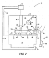
- FIGS. 1-4 are side-view illustrations of laser apparatus 10, which is an industrial laser system suitable for welding metal parts by laser radiation.
- welding refers to a technique for joining at least two metallic parts with an application of heat (e.g., heat from laser radiation), and includes restoration welding with a filler material, and brazing.
- Laser apparatus 10 includes base 12, housing 14, laser 16, laser beam 18, control 20, pedal actuator 22, and safety system 24.
- FIGS. 1-3 depict hand 26 of a user disposed at offset locations from laser beam 18, and outside of nominal hazard zone 28, where laser beam 18 is generated at an operating level intensity by laser 16 for welding metal parts.
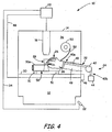
- FIG. 4 depicts user's hand 26 disposed within nominal hazard zone 28 of laser beam 18.
- safety system 24 controls laser 16 to reduce the intensity of laser beam 18 from the operating level to a standby level when user's hand 26 moves within nominal hazard zone 28 of laser beam 18. This reduces the risk of potential injuries from exposure to laser beam 18.
- base 12 is a support base for working with laser 16, and includes surface 30.
- Housing 14 is removably secured to base 12, and protects the user located outside of housing 14 from laser beam 18.
- Housing 14 includes opening 32 through which the user may extend hand 26 to reach within housing 14.
- Housing 14 may be fabricated from a variety of protective materials such as sheet metal, safety glass, and combinations of these and other materials.
- Housing 14 may also include port holes for allowing the user to insert hand 26 within housing 14.
- Housing 14 may be manually or mechanically raised and lowered relative to base 12 to allow the user to insert one or more metal parts on surface 30 prior to laser welding. Additionally, housing 14 may include a housing door for insertion of metal parts.
- Laser 16 is an industrial laser configured for laser welding one or more metal parts. Laser 16 is disposed within housing 14 to generate laser beam 18. While laser 16 is shown entirely within housing 14, portions of laser 16 may alternatively be disposed outside of housing 14 so long as laser beam 18 is emitted within housing 14.
- Laser beam 18 has a maximum power density at focal point 18a, which is the portion of laser beam 18 where the metal parts may be processed.
- Laser beam 18 also includes converging portion 18b located between laser 16 and focal point 18a, and diverging portion 18c located between focal point 18a and surface 30.
- converging portion 18b the power density of laser beam 18 converges toward focal point 18a.
- diverging portion 18c the power density of laser beam 18 diverges from focal point 18a.
- Laser 16 may be vertically raised and lowered relative to surface 30 to vertically adjust the location of focal point 18a of laser beam 18. This is useful for processing metal parts at different heights.
- Focal point 18a is offset at a fixed location relative to laser 16 based on optical settings of laser 16. As such, vertical movement of laser 16 results in an equal movement of focal point 18a.
- the volumetric dimensions of converging portion 18b remain substantially unchanged when laser 16 is vertically moved.
- the volumetric dimensions of diverging portion 18c will vary based on the distance between laser 16 and surface 30.
- suitable volumetric dimensions for converging portion 18b include an inverted cone having a height between laser 16 and focal point 18a ranging from about 5 centimeters to about 15 centimeters and a top base diameter of about 5 centimeters.
- suitable volumetric dimensions for diverging portion 18c include a cone having corresponding vectors to converging portion 18b with a height between focal point 18a and surface 30 ranging from about 7 centimeters to about 40 centimeters.
- Control 20 is a programmable logic controller (PLC) that controls the operation of laser 16 based on received signals, including signals from pedal actuator 22 and safety system 24.
- Control 20 may control the operation of laser 16 in a variety of manners. For example, control 20 may cause laser 16 to generate laser beam 18 having an intensity at an operating level. The operating level provides suitable power for laser beam 18 to laser weld metal parts. Additionally, control 20 may cause laser 16 to reduce the intensity of laser beam 18 from the operating level to a standby level, which is a low or zero intensity level. Examples of suitable standby levels for laser beam 18 include intensities that substantially meet the exposure restrictions described in ANSI Z136.1-2000.
- the intensity of laser beam 18 may be reduced to the standby level by restricting power to laser 16, preventing power to laser 16, defocusing laser beam 18, redirecting laser beam 18, beam dumping (e.g., directing laser beam 18 into a water-cooled beam dump), and combinations thereof.
- Pedal actuator 22 is disposed adjacent base 12 and communicates with control 20 via line 34.
- Pedal actuator 22 switches from a first state to a second state when the user depresses pedal actuator 22, where the states of pedal actuator 22 dictate control of laser 16 by control 20.
- the first state (non-depressed) directs control 20 to deactivate laser 16, or alternatively, cause laser 16 to generate laser beam 18 at the standby level.
- the second state (depressed) directs control 20 to cause laser 16 to generate laser beam 18 at the operating level.
- laser 16 requires the user to manually depress pedal actuator 22 to generate laser beam 18 at the operating level for laser welding.
- the intensity of laser beam 18 is increased based on the how far the user manually depresses pedal actuator 22.
- the operating level of laser beam 18 may be obtained, for example, by fully depressing pedal actuator 22. If the user desires laser beam 18 to be generated at a lower intensity relative to the operating level, the user may partially depress pedal actuator 22. This embodiment provides a greater range of manual control over the intensity of laser beam 18.
- Nominal hazard zone 28 of laser beam 18 is an hourglass-shaped volume located around laser beam 18 that represents a region of greatest risk of skin exposure to laser beam 18. As such, to reduce the risk of direct exposure to laser beam 18 at the operating level, hand 26 of the user should remain outside of nominal hazard zone 28 while laser beam 18 is generated.
- Nominal hazard zone 28 is vertically centered around focal point 18a and extends around converging portion 18b and diverging portion 18c.
- the vertical distances that nominal hazard zone 28 extends above and below focal point 18a may vary based on the power intensity of laser beam 18.
- nominal hazard zone 28 extends to a vertical distance above and below focal point 18a, beyond which the intensity of laser beam 18 is at a low-risk level.
- An example of suitable vertical distances for nominal hazard zone 28 to extend from focal point 18a include about 8 centimeters above focal point 18a and about 8 centimeters below focal point 18a.
- nominal hazard zone 28 may extend the entire vertical distance between laser 16 and surface 30. This encompasses the entire volume of laser beam 18.
- nominal hazard zone 28 extends at a greater radial distance from focal point 18a than from converging portion 18b and diverging portion 18c. This is desirable because the greatest risk of injury from laser beam 18 occurs at focal point 18a, where laser beam 18 is at its highest intensity.
- suitable radial distances between focal point 18a and nominal hazard zone 28 range from about 0.5 centimeters to about 2.5 centimeters.
- suitable radial distances between converging portion 18b/ diverging portion 18c and nominal hazard zone 28 range from no radial distance to about the radial distance between focal point 18a and nominal hazard zone 28.
- nominal hazard zone 28 is described herein as an hourglass-shaped volume, it is understood that nominal hazard zone 28 represents a region of greatest risk of exposure to laser beam 18. As such nominal hazard zone 28 may exhibit different shapes based on how laser beam 18 is generated from laser 16.
- housing 14 The remaining volume within housing 14 that is not occupied by nominal hazard zone 28 is referred to as secondary hazard zone 36 of laser beam 18, which is an ocular hazard zone.
- secondary hazard zone 36 of laser beam 18 is an ocular hazard zone.
- portions of laser beam 18 may reflect or scatter off the metal parts in a variety of directions.
- Housing 14 blocks the reflected and scattered portions of laser beam 18 from directly reaching the user's location outside of housing 14, particularly the user's eyes. However, housing 14 does not directly protect hand 26 of the user while disposed within housing 14.
- Safety system 24 of the present invention protects hand 26 of the user while disposed within housing 14, such as when the user is manipulating metal parts within housing 14.
- Safety system 24 includes glove 38, tether 40, pulley 42, magnet 44, sensor 46, and line 48.
- Glove 38 is a protective barrier capable of receiving hand 26, and is secured to housing 14 around opening 32.
- Glove 38 includes ribbed portion 49, which is an accordion-like or bellows-like portion of glove 38 that is biased toward housing 14 in the direction of arrow A. As such, glove 38 is biased toward a retracted position, as shown in FIG. 1.
- the material of glove 38 absorbs reflected and scattered portions of laser beam 18 within secondary hazard zone 36. This reduces the risk of potential exposure of hand 26 to laser radiation while disposed within housing 14.
- suitable materials for glove 38 include standard rubber glove compounds, such as nitrile-based compounds, neoprene-based compounds, styrene butadiene-based compounds, and combinations thereof. In alternative embodiments, glove 38 may be substituted for other protective barriers that provide exposure protection.
- safety system 24 also protects the user by reducing the intensity of laser beam 18 to the standby level when hand 26 is within nominal hazard zone 28 of laser beam 18. This is accomplished with magnet 44 and sensor 46, where sensor 46 determines the position of hand 26 within housing 14 based on the distance between magnet 44 and sensor 46.
- Magnet 44 is a signal-producing component that emits a magnetic field, and is connected to glove 38 via tether 40.
- Tether 40 includes first end 40a connected to glove 38 and second end 40b connected to magnet 44.
- tether 40 may be integrally formed with glove 38.
- first end 40a of tether 40 may be attached to hand 26 of the user (for example, at the wrist).
- Pulley 42 is rotatably secured at a fixed position that is offset from base 12 and housing 14. Tether 40 extends over pulley 42 such that lateral motion of first end 40a of tether 40 translates to vertical motion of second end 40b of tether 40.
- Sensor 46 is a magnetically-actuated switch capable of sensing the magnetic field of magnet 44.
- suitable devices for sensor 46 include a Hall sensor and a reed switch.
- Sensor 46 is secured to base 12 and communicates with control 20 via line 48.
- Sensor 46 switches between a first state and second state based on whether sensor 46 senses the magnetic field of magnet 44. Sensor 46 is in the first state when the magnetic field is not sensed, and switches to the second state when the magnetic field is sensed.
- the states of sensor 46 direct the control of laser 16 by control 20.
- the first state of sensor 46 does not direct control 20 to control laser 16 in any particular manner.
- laser 16 generates laser beam 18 at the operating level when the user depresses pedal actuator 22.
- the second state of sensor 46 directs control 20 to cause laser 16 to reduce the intensity of laser beam 18 from the operating level to the standby level, regardless of the other received signals.
- the signal associated with the second state of sensor 46 overrides signals from pedal actuator 22, and reduces the intensity of the laser beam 18 to the standby level even when pedal actuator 22 is in the second state.
- Whether sensor 46 senses the magnetic field of magnet 44 is generally based on the distance between magnet 44 and sensor 46, which is correspondingly based on the position of hand 26 of the user. For example, when hand 26 is in the retracted position shown in FIG. 1, magnet 44 is too distant from sensor 46 for sensor 46 to sense the magnetic field of magnet 44. As such, laser 16 may generate laser beam 18 at the operating level for laser processing. However, if hand 26 moves far enough from the retracted position to enter nominal hazard zone 28, magnet 44 will move close enough to sensor 46 for sensor 46 to sense the magnetic field of magnet 44. The intensity of laser beam 16 will then be reduced to the standby level to protect hand 26 of the user from exposure to laser beam 18.
- magnet 44 and sensor 46 may be substituted with other forms of signal-producing components and corresponding sensors, such as linear encoders, signal-threshold sensors that compare signal strengths to minimum signal thresholds, and other components known in the art.
- magnet 44 may be movably connected to a guide rail to limit the range of lateral motion of magnet 44.
- glove 38 may be physically restrained by a tie back (e.g., a chain or a cable) connected to housing 14. The length of the tie back between housing 14 and glove 38 may be selected to physically prevent glove 38 from entering nominal hazard zone 28.
- physical barriers may be positioned adjacent the pathway of laser beam 18 to prevent hand 26 from reaching laser beam 18. For example, a metal, plastic, or glass cone may be placed around converging portion 18b, thereby physically preventing hand 26 from reaching converging portion 18b.
- metal tube 50 is placed within housing 14, and is retained above surface 30 via supports 51.
- Metal tube 50 includes outer surface 50a, which, for this example, is assumed to be damaged and in need of restoration for reuse. As shown, metal tube 50 is positioned such that focal point 18a intersects outer surface 50a. As a result, diverging portion 18c is not generated. Nonetheless, nominal hazard zone 28 remains unchanged because it is based on the pathway of laser beam 18, and is independent of metal parts that temporarily intersect portions of laser beam 18.
- laser apparatus 10 also includes wire 52 and supply spool 53, where wire 52 is a continuous wire of filler material fed from supply spool 53.
- suitable filler materials for wire 52 include any type of metal that may be melted with laser beam 18 (e.g., steel, iron, copper, nickel, cobalt, titanium, brass, and alloys thereof) for restoring outer surface 50a of metal tube 50.
- the filler material may be provided as a rigid rod stock that is manipulated by the user during the laser welding process.
- FIG. 3 shows glove 38 in a partially-extended position, where the user is manipulating wire 52 during a welding process with laser 16.
- the user extends glove 38 from the retracted position by applying a counter force greater than the bias force exerted by ribbed portion 49.
- Glove 38 may be moved from the retracted position to a variety of positions between and including the retracted position and an extended position.
- the user may also move glove 38 in any direction within housing 14, including an axial-rotating motion.
- glove 38 provides a high level of free movement within housing 14, allowing the user to grasp and manipulate metal parts (e.g., wire 52). This is particularly beneficial for laser welding processes, where a high level of dexterity may be required to manipulate the metal parts.
- the user places metal tube 50 on supports 31 and adjusts the height of laser 16 such that focal point 18a is generally located at outer surface 50a of metal tube 50.
- the user grasps wire 52 with hand 26, and manually feeds wire 52 to a process location that is adjacent outer surface 50a and is in a pathway of laser beam 18, as shown in FIG. 3.
- a length of wire 52 is cut from supply spool 53 prior to the welding process.
- the user then depresses pedal 22, thereby generating laser beam 18 at an operating level for laser welding.
- Laser beam 18 melts the portion of wire 52 in the pathway of laser beam 18, allowing the melted portion of wire 52 to fuse to outer surface 50a.
- outer surface 50a is generally located at focal point 18a.
- wire 52 is positioned within converging portion 18b. This arrangement is beneficial because the energy of laser beam 18 is less focused at converging portion 18b compared to focal point 18a. This distributes the applied heat over a greater area of wire 52, thereby providing a more uniform melting of wire 52 and reducing the risk of superheating wire 52.
- metal tube 50 and wire 52 are moved relative to laser beam 18 to weld successive portions of metal tube 50.
- hand 26 is protected by safety system 24, metal tube 50 and wire 52 may be manually moved.
- hand 26 may grasp and move both metal tube 50 and wire 52 relative to laser beam 18 for melting successive portions of wire 52, which fuse to successive portions of outer surface 50a of metal tube 50.
- the user may use a second hand (not shown) to move metal tube 50.
- successive portions of wire 52 are manually fed with hand 26 to the process location for welding the filler material to outer surface 50a. As successive welded portions of metal tube 50 move out of the pathway of laser beam 18, the melted filler material cools and fuses to outer surface 50a, thereby restoring outer surface 50a.
- the user may adjust the manipulations to account for a variety of processing factors.
- the filler material of wire 52 is typically a memory material that retains the curvature induced by supply spool 53. This curvature also increases as wire 52 is consumed from supply spool 53 due to the tightening curvature of wire 52 around supply spool 53. Manually placing wire 52 at the processing location allows the user to correct for this increasing curvature and any other welding anomalies associated with filler material wire delivery.
- magnet 44 and sensor 46 are positioned such that sensor 46 senses the magnetic field of magnet 44 and switches states when hand 26 of the user enters nominal hazard zone 28.
- magnet 44 When the user extends hand 26 from the retracted position toward nominal hazard zone 28, magnet 44 vertically raises. As such, magnet 44 moves closer to sensor 46.
- hand 26 reaches nominal hazard zone 28 magnet 44 is close enough to sensor 46 for sensor 46 to sense the magnetic field of magnet 44.
- Control 20 then causes laser 16 to reduce the intensity of laser beam 18 to the standby level, as discussed above. This automatically reduces the intensity of laser beam 18 to a safe or zero-intensity level while hand 26 of the user is disposed within nominal hazard zone 28. Therefore, the user is not required to manually deactivate laser 16 to work within nominal hazard zone 28.
- FIG. 4 shows glove 38 in an extended position, where user's hand 26 extends within nominal hazard zone 28.
- the intensity of laser beam 18 is reduced to the standby level, which prevents laser beam 18 from injuring hand 26.
- magnet 44 vertically lowers, thereby moving away from sensor 46.
- sensor 46 no longer senses the magnetic field of magnet 44.
- Sensor 46 then switches back to the first state, and the intensity of laser beam 18 increases back to the operating level in response to the user depressing pedal actuator 22.
- Safety system 24 reduces the intensity of laser beam 18 to a safe or zero-intensity level while hand 26 is within nominal hazard zone 28 and allows the intensity of laser 16 increase back to the operating level when hand 26 leaves nominal hazard zone 28. This reduces the risk of exposure to laser beam 18, thereby increasing safety when welding with laser 16.
- FIGS. 5-7 are side-view illustrations of laser apparatus 110, which is another industrial laser system suitable for processing work pieces by laser radiation.
- laser apparatus 110 is similar to laser apparatus 10 in FIGS. 1-4 (respective reference labels are increased by 100), except that safety system 124 is used in place of safety system 24.
- Safety system 124 protects hand 126 of the user while disposed within housing 114, such as when the user is manipulating metal parts (e.g., metal tube 150 and wire 152) within housing 114.
- Safety system 124 includes glove 138 and emitter/sensor 154, which communicates with control 120 via line 148.
- Glove 138 functions in the same manner as discussed above in FIG. 1 for glove 38.
- Glove 138 may absorb reflected and scattered portions of laser beam 118 within secondary hazard zone 136, and provides a high level of free movement within housing 114.
- glove 138 may include fluorescent materials (e.g., ultraviolet (UV)-luminescent materials such as inks, pigments, and dyes) for allowing emitter/sensor 154 to detect the position of hand 126 of the user within housing 114.
- the fluorescent materials may be included in the molding materials used to fabricate glove 138, or alternatively, glove 138 may be encased in a coating, film, or wrapping that includes the fluorescent materials.
- the fluorescent materials allow glove 138 to emit light at a particular wavelength (referred to herein as "signal-wavelength light”) when glove 138 absorbs UV-wavelength light.
- signal-wavelength light a particular wavelength
- the particular wavelength of the photons emitted from glove 138 i.e., the signal-wavelength light
- Emitter/sensor 154 is disposed within housing 114 and is a combined emitter/sensor system that includes UV-beam emitter 156 and sensor 158.
- Example of suitable systems for emitter/sensor 154 include the trade designated “UVX 100" and “UVX 300" Luminescence Sensors, which are commercially available from EMX Industries, Inc., Cleveland, OH.
- UV-beam emitter 156 is a signal-producing component that emits UV beam 160.
- UV beam 160 is a diverging beam directed toward surface 130, and which extends around laser beam 118, as shown in FIG. 3. Because surface 130 and metal tube 150 generally do not include fluorescent materials, surface 130 and the metal tube 150 do not emit signal-wavelength light. However, because glove 138 contains fluorescent materials, glove 138 absorbs portions of UV beam 160 while disposed within UV beam 160, and emits signal-wavelength light.
- UV beam 160 is desirably positioned such that it encompasses focal point 118a of laser beam 118, which is the location of the maximum power density of laser beam 118. Even more desirably, UV beam 160 is positioned such that it substantially encompasses a nominal hazard zone of laser beam 118 (not shown), similar to nominal hazard zone 28 discussed above in FIG. 1. This allows UV beam 160 to be directed at glove 138 when glove 138 enters the nominal hazard zone of laser beam 118.
- Sensor 158 is a sensor for sensing signal-wavelength light emitted toward emitter/sensor 154.
- Sensor 158 includes electronics that generate an output signal to control 120 via line 148.
- the output signal has a first state and a second state based on whether sensor 158 senses signal-wavelength light having an intensity that equals or exceeds a preset threshold.
- the output signal of sensor 158 is in the first state when sensor 158 does not sense any signal-wavelength light or when the intensity of sensed signal-wavelength light does not exceed the preset threshold.
- the output signal of sensor 158 switches to the second state when the intensity of sensed signal-wavelength light equals or exceeds the preset threshold.
- the preset threshold prevents the output signal of sensor 158 from accidentally switching to the second state due to the detection of background signal-wavelength light. For example, during a laser welding operation, a measurable amount of signal-wavelength light may be emitted from melted metal of wire 152. Therefore, the preset threshold is desirably set above the intensity of such background signal-wavelength light. This allows sensor 158 to discriminate between sensed signal-wavelength light emitted from glove 138 and background signal-wavelength light. Accordingly, UV-beam emitter 156 desirably emits UV beam 160 at an intensity that allows glove 138 to emit signal-wavelength light at an intensity that is greater than the preset threshold. This allows the portions of signal-wavelength light emitted from glove 138 toward emitter/sensor 154 to exceed the preset threshold.
- the states of the output signal of sensor 158 direct the control of laser 116 by control 120 in a similar manner to that discussed above in FIG. 1 for sensor 46.
- the first state of the output signal does not direct control 120 to control laser 116 in any particular manner.
- laser 116 generates laser beam 118 at the operating level when the user depresses pedal actuator 122.
- the second state of the output signal directs control 120 to cause laser 116 to reduce the intensity of laser beam 118 from the operating level to the standby level, regardless of the other received signals.
- the output signal in the second state of sensor 158 overrides signals from pedal actuator 122, and reduces the intensity of the laser beam 118 to the standby level even when pedal actuator 122 is in the second state.
- glove 138 is in a partially-extended position while the user is manipulating wire 152 during a welding process with laser 116.
- the user extends glove 138 from the retracted position by applying a counter force greater than the bias force exerted by ribbed portion 150.
- Glove 138 may be moved from the retracted position to a variety of positions between and including the retracted position and the extended position.
- the user grasps wire 152 with hand 126, and manually feeds wire 152 to a process location that is adjacent outer surface 150a and is in a pathway of laser beam 118, as shown in FIG. 6.
- the user then depresses pedal 122, thereby generating laser beam 118 at an operating level for laser welding.
- Laser beam 118 melts the portion of wire 152 in the pathway of laser beam 118, allowing the melted portion of wire 152 to fuse to outer surface 150a.
- the user moves hand 126 and glove 138 to various positions within housing 114.
- Whether sensor 158 senses signal-wavelength light is generally based on the position of hand 126 of the user and glove 138. For example, when glove 138 is in the retracted position (as shown above in FIG. 5) or in a partially-extended position (as shown in FIG. 6), glove 138 is not disposed within UV beam 160. As such, laser 116 may generate laser beam 118 at the operating level for laser processing. However, if hand 126 moves far enough from the retracted position, glove 138 will enter UV beam 160, thereby absorbing portions of UV beam 160 and emitting signal-wavelength light toward emitter/sensor 154. Because the intensity of the sensed signal-wavelength light exceeds the preset threshold, the intensity of laser beam 116 will then be reduced to the standby level to protect hand 126 of the user from exposure to laser beam 118.
- FIG. 7 shows glove 138 in an extended position, where user's hand 126 extends within UV beam 160.
- portions of UV beam 160 absorb into glove 138, which causes signal-wavelength light to emit from glove 138. While the emitted signal-wavelength light is scattered within housing 114, portions of signal-wavelength light are directed toward emitter/sensor 154. Sensor 158 then senses these portions of signal-wavelength light. Because the sensed portions of signal-wavelength light are emitted from glove 138, the intensities exceed the preset threshold. Control 120 then correspondingly causes laser 116 to reduce the intensity of laser beam 118 to the standby level. This automatically reduces the intensity of laser beam 118 to a safe or zero-intensity level while hand 126 of the user is disposed within UV beam 160. Therefore, the user is not required to manually deactivate laser 116 to work within the region of UV beam 160.
- Safety system 124 reduces the intensity of laser beam 118 to a safe or zero-intensity level while hand 126 is within UV beam 160 and allows the intensity of laser 116 increase back to the operating level when hand 126 leaves UV beam 160. This reduces the risk of exposure to laser beam 118, thereby increasing safety when welding with laser 116.
- emitter/sensor 154 may alternatively emit and detect light wavelengths of particular colors (rather than UV-wavelength light).
- suitable color-based systems for emitter/sensor 154 include the trade designated “COLORMAX-1000 DISCRETE", “COLORMAX-1000 HEX” and “COLORMAX-1000 RGB” Color Sensors, which are commercially available from EMX Industries, Inc., Cleveland, OH.
- glove 138 may include materials that reflect or emit the given color associated with the color sensor for detecting when glove 138 enters the given color beam.
- laser apparatuses 10 and 110 are each disclosed above as having a single safety system (e.g., safety systems 24 and 124), multiple safety systems of the present invention may be used.
- a pair of safety systems 24 are desirably used so that the user may safely work with both hands within housing 14.
- multiple safety systems 124 may be used to increase the volumetric coverage of UV beams 160.
Landscapes
- Engineering & Computer Science (AREA)
- Physics & Mathematics (AREA)
- Optics & Photonics (AREA)
- Mechanical Engineering (AREA)
- Plasma & Fusion (AREA)
- General Engineering & Computer Science (AREA)
- Laser Beam Processing (AREA)
Abstract
A method for welding a metal part (50) with a laser (116) that generates a laser beam (18), where the method includes manually feeding successive portions of a filler material (52) adjacent the metal part (50) and in a pathway of the laser beam (18), generating the laser beam (18) for melting the filler material (52), and cooling the melted filler material (52) for fusing the filler material (52) to the metal part (50). The method further includes controlling an intensity of the laser beam (16) based on a sensed position of a user's hand (26) relative to the laser beam (18).
Description
- The present invention relates to laser welding techniques. In particular, the present invention relates to a method of manually welding metal parts with a laser while protecting a user with a safety control system.
- Lasers generate laser beams that are used for a variety of industrial applications, such as laser welding. Laser welding is a suitable technique for restoring damaged metal parts and for joining multiple metal parts. With respect to restoring damaged metal parts, industrial metal parts may be damaged due to chemical and frictional erosion over extended periods of use. Such damage typically includes cracks or holes in the metal parts, which prevents the metal parts from functioning properly. In lieu of replacing the damaged metal parts with new parts, the damaged metal parts may be restored via welding processes (e.g., laser welding), in which filler materials are melted and fused over the cracks and holes to seal up the damage. The restored metal parts may then be reused for the given industrial applications.
- Due to the nature of laser beams, numerous safety measures have been implemented to protect users from bodily injury. In response to safety concerns, the American National Standard Institute (ANSI) presented ANSI Z136.1-2000, which provides guidelines and recommendations for the safe use of a variety of lasers. One common technique for avoiding injuries and bums from accidental exposures to laser beams involves the use of automated laser welding systems, which eliminate direct user interaction. Automated laser welding systems attempt to mimic manual welding via computer vision, neural networks, and computer algorithms. However, because of the variety of part configurations required, there is a need for laser welding techniques that allow good part manipulation while also reducing the risk of user injuries.
- The present invention relates to a method for welding a metal part with a laser that generates a laser beam. The method includes manually feeding successive portions of a filler material with a hand of a user to a process location that is adjacent the metal part and is in a pathway of the laser beam. The method also includes generating the laser beam, which melts the manually fed successive portions of the filler material, and cooling the melted successive portions of the filler material, thereby allowing the melted successive portions to fuse to the metal part. Furthermore, the method includes controlling an intensity of the laser beam based on a sensed position of the user's hand relative to the laser beam.
-
- FIG. 1 is a side-view illustration of a laser apparatus, which includes a laser control safety system having a glove in a retracted position.
- FIG. 2 is a side-view illustration of the laser apparatus, which includes the laser control safety system having the glove in the retracted position, and further includes a metal tube and filler material supply spool.
- FIG. 3 is a side-view illustration of the laser apparatus, which includes the laser control safety system having the glove in a partially-extended position during a laser welding process.
- FIG. 4 is a side-view illustration of the laser apparatus, which includes the laser control safety system having the glove in an extended position.
- FIG. 5 is a side-view illustration of a laser apparatus, which includes an alternative laser control safety system having a glove in a retracted position.
- FIG. 6 is a side-view illustration of the laser apparatus, which includes the alternative laser control safety system having the glove in a partially-extended position during a laser welding process.
- FIG. 7 is a side-view illustration of the laser apparatus, which includes the alternative laser control safety system having the glove in an extended position.
- FIGS. 1-4 are side-view illustrations of
laser apparatus 10, which is an industrial laser system suitable for welding metal parts by laser radiation. As used herein, the term "welding" refers to a technique for joining at least two metallic parts with an application of heat (e.g., heat from laser radiation), and includes restoration welding with a filler material, and brazing.Laser apparatus 10 includesbase 12,housing 14,laser 16,laser beam 18,control 20,pedal actuator 22, andsafety system 24. - FIGS. 1-3 depict
hand 26 of a user disposed at offset locations fromlaser beam 18, and outside ofnominal hazard zone 28, wherelaser beam 18 is generated at an operating level intensity bylaser 16 for welding metal parts. FIG. 4 depicts user'shand 26 disposed withinnominal hazard zone 28 oflaser beam 18. As discussed below,safety system 24 controlslaser 16 to reduce the intensity oflaser beam 18 from the operating level to a standby level when user'shand 26 moves withinnominal hazard zone 28 oflaser beam 18. This reduces the risk of potential injuries from exposure tolaser beam 18. - As shown in FIG. 1,
base 12 is a support base for working withlaser 16, and includessurface 30.Housing 14 is removably secured tobase 12, and protects the user located outside ofhousing 14 fromlaser beam 18.Housing 14 includes opening 32 through which the user may extendhand 26 to reach withinhousing 14.Housing 14 may be fabricated from a variety of protective materials such as sheet metal, safety glass, and combinations of these and other materials.Housing 14 may also include port holes for allowing the user to inserthand 26 withinhousing 14.Housing 14 may be manually or mechanically raised and lowered relative tobase 12 to allow the user to insert one or more metal parts onsurface 30 prior to laser welding. Additionally,housing 14 may include a housing door for insertion of metal parts. - Laser 16 is an industrial laser configured for laser welding one or more metal parts. Laser 16 is disposed within
housing 14 to generatelaser beam 18. Whilelaser 16 is shown entirely withinhousing 14, portions oflaser 16 may alternatively be disposed outside ofhousing 14 so long aslaser beam 18 is emitted withinhousing 14. -
Laser beam 18 has a maximum power density atfocal point 18a, which is the portion oflaser beam 18 where the metal parts may be processed.Laser beam 18 also includesconverging portion 18b located betweenlaser 16 andfocal point 18a, and divergingportion 18c located betweenfocal point 18a andsurface 30. At convergingportion 18b, the power density oflaser beam 18 converges towardfocal point 18a. Correspondingly, at divergingportion 18c, the power density oflaser beam 18 diverges fromfocal point 18a. -
Laser 16 may be vertically raised and lowered relative tosurface 30 to vertically adjust the location offocal point 18a oflaser beam 18. This is useful for processing metal parts at different heights.Focal point 18a is offset at a fixed location relative tolaser 16 based on optical settings oflaser 16. As such, vertical movement oflaser 16 results in an equal movement offocal point 18a. Correspondingly, the volumetric dimensions of convergingportion 18b remain substantially unchanged whenlaser 16 is vertically moved. However, the volumetric dimensions of divergingportion 18c will vary based on the distance betweenlaser 16 andsurface 30. - An example of suitable volumetric dimensions for converging
portion 18b include an inverted cone having a height betweenlaser 16 andfocal point 18a ranging from about 5 centimeters to about 15 centimeters and a top base diameter of about 5 centimeters. Examples of suitable volumetric dimensions for divergingportion 18c include a cone having corresponding vectors to convergingportion 18b with a height betweenfocal point 18a andsurface 30 ranging from about 7 centimeters to about 40 centimeters. -
Control 20 is a programmable logic controller (PLC) that controls the operation oflaser 16 based on received signals, including signals frompedal actuator 22 andsafety system 24.Control 20 may control the operation oflaser 16 in a variety of manners. For example,control 20 may causelaser 16 to generatelaser beam 18 having an intensity at an operating level. The operating level provides suitable power forlaser beam 18 to laser weld metal parts. Additionally,control 20 may causelaser 16 to reduce the intensity oflaser beam 18 from the operating level to a standby level, which is a low or zero intensity level. Examples of suitable standby levels forlaser beam 18 include intensities that substantially meet the exposure restrictions described in ANSI Z136.1-2000. The intensity oflaser beam 18 may be reduced to the standby level by restricting power tolaser 16, preventing power tolaser 16, defocusinglaser beam 18, redirectinglaser beam 18, beam dumping (e.g., directinglaser beam 18 into a water-cooled beam dump), and combinations thereof. - The user operates
laser 16 withpedal actuator 22, which is a pedal-operated actuator switch foroperating laser 16.Pedal actuator 22 is disposedadjacent base 12 and communicates withcontrol 20 vialine 34.Pedal actuator 22 switches from a first state to a second state when the user depressespedal actuator 22, where the states ofpedal actuator 22 dictate control oflaser 16 bycontrol 20. The first state (non-depressed) directscontrol 20 to deactivatelaser 16, or alternatively, causelaser 16 to generatelaser beam 18 at the standby level. The second state (depressed) directscontrol 20 to causelaser 16 to generatelaser beam 18 at the operating level. As such,laser 16 requires the user to manually depresspedal actuator 22 to generatelaser beam 18 at the operating level for laser welding. - In one embodiment, the intensity of
laser beam 18 is increased based on the how far the user manually depressespedal actuator 22. In this embodiment, the operating level oflaser beam 18 may be obtained, for example, by fully depressingpedal actuator 22. If the user desireslaser beam 18 to be generated at a lower intensity relative to the operating level, the user may partially depresspedal actuator 22. This embodiment provides a greater range of manual control over the intensity oflaser beam 18. -
Nominal hazard zone 28 oflaser beam 18 is an hourglass-shaped volume located aroundlaser beam 18 that represents a region of greatest risk of skin exposure tolaser beam 18. As such, to reduce the risk of direct exposure tolaser beam 18 at the operating level,hand 26 of the user should remain outside ofnominal hazard zone 28 whilelaser beam 18 is generated. -
Nominal hazard zone 28 is vertically centered aroundfocal point 18a and extends around convergingportion 18b and divergingportion 18c. The vertical distances thatnominal hazard zone 28 extends above and belowfocal point 18a may vary based on the power intensity oflaser beam 18. In one embodiment, shown in FIG. 1,nominal hazard zone 28 extends to a vertical distance above and belowfocal point 18a, beyond which the intensity oflaser beam 18 is at a low-risk level. An example of suitable vertical distances fornominal hazard zone 28 to extend fromfocal point 18a include about 8 centimeters abovefocal point 18a and about 8 centimeters belowfocal point 18a. In an alternative embodiment,nominal hazard zone 28 may extend the entire vertical distance betweenlaser 16 andsurface 30. This encompasses the entire volume oflaser beam 18. - As further shown in FIG. 1,
nominal hazard zone 28 extends at a greater radial distance fromfocal point 18a than from convergingportion 18b and divergingportion 18c. This is desirable because the greatest risk of injury fromlaser beam 18 occurs atfocal point 18a, wherelaser beam 18 is at its highest intensity. Examples of suitable radial distances betweenfocal point 18a andnominal hazard zone 28 range from about 0.5 centimeters to about 2.5 centimeters. Examples of suitable radial distances between convergingportion 18b/ divergingportion 18c andnominal hazard zone 28 range from no radial distance to about the radial distance betweenfocal point 18a andnominal hazard zone 28. Whilenominal hazard zone 28 is described herein as an hourglass-shaped volume, it is understood thatnominal hazard zone 28 represents a region of greatest risk of exposure tolaser beam 18. As suchnominal hazard zone 28 may exhibit different shapes based on howlaser beam 18 is generated fromlaser 16. - The remaining volume within
housing 14 that is not occupied bynominal hazard zone 28 is referred to assecondary hazard zone 36 oflaser beam 18, which is an ocular hazard zone. During laser welding, portions oflaser beam 18 may reflect or scatter off the metal parts in a variety of directions.Housing 14 blocks the reflected and scattered portions oflaser beam 18 from directly reaching the user's location outside ofhousing 14, particularly the user's eyes. However,housing 14 does not directly protecthand 26 of the user while disposed withinhousing 14. -
Safety system 24 of the present invention protectshand 26 of the user while disposed withinhousing 14, such as when the user is manipulating metal parts withinhousing 14.Safety system 24 includesglove 38,tether 40,pulley 42,magnet 44,sensor 46, andline 48.Glove 38 is a protective barrier capable of receivinghand 26, and is secured tohousing 14 aroundopening 32.Glove 38 includes ribbedportion 49, which is an accordion-like or bellows-like portion ofglove 38 that is biased towardhousing 14 in the direction of arrow A. As such,glove 38 is biased toward a retracted position, as shown in FIG. 1. - The material of
glove 38 absorbs reflected and scattered portions oflaser beam 18 withinsecondary hazard zone 36. This reduces the risk of potential exposure ofhand 26 to laser radiation while disposed withinhousing 14. Examples of suitable materials forglove 38 include standard rubber glove compounds, such as nitrile-based compounds, neoprene-based compounds, styrene butadiene-based compounds, and combinations thereof. In alternative embodiments,glove 38 may be substituted for other protective barriers that provide exposure protection. - In addition to the exposure protection provided by
glove 38,safety system 24 also protects the user by reducing the intensity oflaser beam 18 to the standby level whenhand 26 is withinnominal hazard zone 28 oflaser beam 18. This is accomplished withmagnet 44 andsensor 46, wheresensor 46 determines the position ofhand 26 withinhousing 14 based on the distance betweenmagnet 44 andsensor 46.Magnet 44 is a signal-producing component that emits a magnetic field, and is connected toglove 38 viatether 40. -
Tether 40 includesfirst end 40a connected toglove 38 andsecond end 40b connected tomagnet 44. In an alternative embodiment,tether 40 may be integrally formed withglove 38. In another alternative embodiment, whereglove 38 is not used,first end 40a oftether 40 may be attached tohand 26 of the user (for example, at the wrist).Pulley 42 is rotatably secured at a fixed position that is offset frombase 12 andhousing 14.Tether 40 extends overpulley 42 such that lateral motion offirst end 40a oftether 40 translates to vertical motion ofsecond end 40b oftether 40. -
Sensor 46 is a magnetically-actuated switch capable of sensing the magnetic field ofmagnet 44. Examples of suitable devices forsensor 46 include a Hall sensor and a reed switch.Sensor 46 is secured tobase 12 and communicates withcontrol 20 vialine 48.Sensor 46 switches between a first state and second state based on whethersensor 46 senses the magnetic field ofmagnet 44.Sensor 46 is in the first state when the magnetic field is not sensed, and switches to the second state when the magnetic field is sensed. - The states of
sensor 46 direct the control oflaser 16 bycontrol 20. The first state ofsensor 46 does not directcontrol 20 to controllaser 16 in any particular manner. As such,laser 16 generateslaser beam 18 at the operating level when the user depressespedal actuator 22. The second state ofsensor 46, however, directscontrol 20 to causelaser 16 to reduce the intensity oflaser beam 18 from the operating level to the standby level, regardless of the other received signals. As such, the signal associated with the second state ofsensor 46 overrides signals frompedal actuator 22, and reduces the intensity of thelaser beam 18 to the standby level even whenpedal actuator 22 is in the second state. - Whether
sensor 46 senses the magnetic field ofmagnet 44 is generally based on the distance betweenmagnet 44 andsensor 46, which is correspondingly based on the position ofhand 26 of the user. For example, whenhand 26 is in the retracted position shown in FIG. 1,magnet 44 is too distant fromsensor 46 forsensor 46 to sense the magnetic field ofmagnet 44. As such,laser 16 may generatelaser beam 18 at the operating level for laser processing. However, ifhand 26 moves far enough from the retracted position to enternominal hazard zone 28,magnet 44 will move close enough tosensor 46 forsensor 46 to sense the magnetic field ofmagnet 44. The intensity oflaser beam 16 will then be reduced to the standby level to protecthand 26 of the user from exposure tolaser beam 18. - In alterative embodiments of the present invention,
magnet 44 andsensor 46 may be substituted with other forms of signal-producing components and corresponding sensors, such as linear encoders, signal-threshold sensors that compare signal strengths to minimum signal thresholds, and other components known in the art. Additionally,magnet 44 may be movably connected to a guide rail to limit the range of lateral motion ofmagnet 44. Furthermore,glove 38 may be physically restrained by a tie back (e.g., a chain or a cable) connected tohousing 14. The length of the tie back betweenhousing 14 andglove 38 may be selected to physically preventglove 38 from enteringnominal hazard zone 28. In additional embodiments, physical barriers may be positioned adjacent the pathway oflaser beam 18 to preventhand 26 from reachinglaser beam 18. For example, a metal, plastic, or glass cone may be placed around convergingportion 18b, thereby physically preventinghand 26 from reaching convergingportion 18b. - As shown in FIG. 2,
metal tube 50 is placed withinhousing 14, and is retained abovesurface 30 via supports 51.Metal tube 50 includesouter surface 50a, which, for this example, is assumed to be damaged and in need of restoration for reuse. As shown,metal tube 50 is positioned such thatfocal point 18a intersectsouter surface 50a. As a result, divergingportion 18c is not generated. Nonetheless,nominal hazard zone 28 remains unchanged because it is based on the pathway oflaser beam 18, and is independent of metal parts that temporarily intersect portions oflaser beam 18. - As further shown in FIG. 2,
laser apparatus 10 also includeswire 52 andsupply spool 53, wherewire 52 is a continuous wire of filler material fed fromsupply spool 53. Examples of suitable filler materials forwire 52 include any type of metal that may be melted with laser beam 18 (e.g., steel, iron, copper, nickel, cobalt, titanium, brass, and alloys thereof) for restoringouter surface 50a ofmetal tube 50. In an alternative embodiment, the filler material may be provided as a rigid rod stock that is manipulated by the user during the laser welding process. - FIG. 3 shows
glove 38 in a partially-extended position, where the user is manipulatingwire 52 during a welding process withlaser 16. The user extendsglove 38 from the retracted position by applying a counter force greater than the bias force exerted byribbed portion 49.Glove 38 may be moved from the retracted position to a variety of positions between and including the retracted position and an extended position. The user may also moveglove 38 in any direction withinhousing 14, including an axial-rotating motion. As such,glove 38 provides a high level of free movement withinhousing 14, allowing the user to grasp and manipulate metal parts (e.g., wire 52). This is particularly beneficial for laser welding processes, where a high level of dexterity may be required to manipulate the metal parts. - During a welding operation, the user places
metal tube 50 on supports 31 and adjusts the height oflaser 16 such thatfocal point 18a is generally located atouter surface 50a ofmetal tube 50. The user then graspswire 52 withhand 26, and manually feedswire 52 to a process location that is adjacentouter surface 50a and is in a pathway oflaser beam 18, as shown in FIG. 3. Typically, a length ofwire 52 is cut fromsupply spool 53 prior to the welding process. The user then depressespedal 22, thereby generatinglaser beam 18 at an operating level for laser welding.Laser beam 18 melts the portion ofwire 52 in the pathway oflaser beam 18, allowing the melted portion ofwire 52 to fuse toouter surface 50a. - As discussed above,
outer surface 50a is generally located atfocal point 18a. As a result,wire 52 is positioned within convergingportion 18b. This arrangement is beneficial because the energy oflaser beam 18 is less focused at convergingportion 18b compared tofocal point 18a. This distributes the applied heat over a greater area ofwire 52, thereby providing a more uniform melting ofwire 52 and reducing the risk of superheatingwire 52. - Because
laser 16 is a fixed laser,metal tube 50 andwire 52 are moved relative tolaser beam 18 to weld successive portions ofmetal tube 50. Becausehand 26 is protected bysafety system 24,metal tube 50 andwire 52 may be manually moved. For example,hand 26 may grasp and move bothmetal tube 50 andwire 52 relative tolaser beam 18 for melting successive portions ofwire 52, which fuse to successive portions ofouter surface 50a ofmetal tube 50. Alternatively, the user may use a second hand (not shown) to movemetal tube 50. In either alternative, successive portions ofwire 52 are manually fed withhand 26 to the process location for welding the filler material toouter surface 50a. As successive welded portions ofmetal tube 50 move out of the pathway oflaser beam 18, the melted filler material cools and fuses toouter surface 50a, thereby restoringouter surface 50a. - When welding large holes in metal parts, such as a large hole in
outer surface 50a, successive portions of filler material are desirably fused toouter surface 50a and to previously fused portions of filler material in a parallel manner. Under this technique, multiple parallel bead paths of fused material are sequentially welded to seal the hole inouter surface 50a. Each pass desirably consumes about 30% to about 50% of a previously welded pass. This increases the strength of the resulting weld. - Because the user manually manipulates
wire 52, the user may adjust the manipulations to account for a variety of processing factors. For example, the filler material ofwire 52 is typically a memory material that retains the curvature induced bysupply spool 53. This curvature also increases aswire 52 is consumed fromsupply spool 53 due to the tightening curvature ofwire 52 aroundsupply spool 53. Manually placingwire 52 at the processing location allows the user to correct for this increasing curvature and any other welding anomalies associated with filler material wire delivery. - As discussed above, during the laser welding operation,
safety system 24 reduces the risk of potential injuries from exposure tolaser beam 18. In one embodiment,magnet 44 andsensor 46 are positioned such thatsensor 46 senses the magnetic field ofmagnet 44 and switches states whenhand 26 of the user entersnominal hazard zone 28. When the user extendshand 26 from the retracted position towardnominal hazard zone 28,magnet 44 vertically raises. As such,magnet 44 moves closer tosensor 46. Whenhand 26 reachesnominal hazard zone 28,magnet 44 is close enough tosensor 46 forsensor 46 to sense the magnetic field ofmagnet 44.Control 20 then causeslaser 16 to reduce the intensity oflaser beam 18 to the standby level, as discussed above. This automatically reduces the intensity oflaser beam 18 to a safe or zero-intensity level whilehand 26 of the user is disposed withinnominal hazard zone 28. Therefore, the user is not required to manually deactivatelaser 16 to work withinnominal hazard zone 28. - FIG. 4 shows
glove 38 in an extended position, where user'shand 26 extends withinnominal hazard zone 28. In this situation, the intensity oflaser beam 18 is reduced to the standby level, which preventslaser beam 18 from injuringhand 26. When the user moveshand 26 toward the retracted position,magnet 44 vertically lowers, thereby moving away fromsensor 46. Ashand 26 exitsnominal hazard zone 28,sensor 46 no longer senses the magnetic field ofmagnet 44.Sensor 46 then switches back to the first state, and the intensity oflaser beam 18 increases back to the operating level in response to the user depressingpedal actuator 22.. - Accordingly, while depressing
pedal actuator 22, the user may repeatedly movehand 26 in and outnominal hazard zone 28 without the worry of accidental exposure tolaser beam 18.Safety system 24 reduces the intensity oflaser beam 18 to a safe or zero-intensity level whilehand 26 is withinnominal hazard zone 28 and allows the intensity oflaser 16 increase back to the operating level whenhand 26 leavesnominal hazard zone 28. This reduces the risk of exposure tolaser beam 18, thereby increasing safety when welding withlaser 16. - FIGS. 5-7 are side-view illustrations of
laser apparatus 110, which is another industrial laser system suitable for processing work pieces by laser radiation. As shown in FIG. 5,laser apparatus 110 is similar tolaser apparatus 10 in FIGS. 1-4 (respective reference labels are increased by 100), except thatsafety system 124 is used in place ofsafety system 24.Safety system 124 protectshand 126 of the user while disposed withinhousing 114, such as when the user is manipulating metal parts (e.g.,metal tube 150 and wire 152) withinhousing 114.Safety system 124 includesglove 138 and emitter/sensor 154, which communicates withcontrol 120 vialine 148. -
Glove 138 functions in the same manner as discussed above in FIG. 1 forglove 38.Glove 138 may absorb reflected and scattered portions oflaser beam 118 withinsecondary hazard zone 136, and provides a high level of free movement withinhousing 114. Additionally,glove 138 may include fluorescent materials (e.g., ultraviolet (UV)-luminescent materials such as inks, pigments, and dyes) for allowing emitter/sensor 154 to detect the position ofhand 126 of the user withinhousing 114. The fluorescent materials may be included in the molding materials used to fabricateglove 138, or alternatively,glove 138 may be encased in a coating, film, or wrapping that includes the fluorescent materials. - The fluorescent materials allow
glove 138 to emit light at a particular wavelength (referred to herein as "signal-wavelength light") whenglove 138 absorbs UV-wavelength light. In particular, when UV-wavelength light is directed atglove 138, electrons of the fluorescent materials inglove 138 absorb photons from the UV-wavelength light, causing the electrons to jump from their original energy states to higher energy states. Photons are then released fromglove 138 when the electrons drop down to lower energy states. However, the lower energy states obtained differ from the original energy states, which results in the released photons having longer wavelengths than the UV-wavelength light. The particular wavelength of the photons emitted from glove 138 (i.e., the signal-wavelength light) generally depends on the types and concentrations of the fluorescent materials used. - Emitter/
sensor 154 is disposed withinhousing 114 and is a combined emitter/sensor system that includes UV-beam emitter 156 andsensor 158. Example of suitable systems for emitter/sensor 154 include the trade designated "UVX 100" and "UVX 300" Luminescence Sensors, which are commercially available from EMX Industries, Inc., Cleveland, OH. - UV-
beam emitter 156 is a signal-producing component that emitsUV beam 160.UV beam 160 is a diverging beam directed towardsurface 130, and which extends aroundlaser beam 118, as shown in FIG. 3. Becausesurface 130 andmetal tube 150 generally do not include fluorescent materials,surface 130 and themetal tube 150 do not emit signal-wavelength light. However, becauseglove 138 contains fluorescent materials,glove 138 absorbs portions ofUV beam 160 while disposed withinUV beam 160, and emits signal-wavelength light. -
UV beam 160 is desirably positioned such that it encompassesfocal point 118a oflaser beam 118, which is the location of the maximum power density oflaser beam 118. Even more desirably,UV beam 160 is positioned such that it substantially encompasses a nominal hazard zone of laser beam 118 (not shown), similar tonominal hazard zone 28 discussed above in FIG. 1. This allowsUV beam 160 to be directed atglove 138 whenglove 138 enters the nominal hazard zone oflaser beam 118. -
Sensor 158 is a sensor for sensing signal-wavelength light emitted toward emitter/sensor 154.Sensor 158 includes electronics that generate an output signal to control 120 vialine 148. The output signal has a first state and a second state based on whethersensor 158 senses signal-wavelength light having an intensity that equals or exceeds a preset threshold. The output signal ofsensor 158 is in the first state whensensor 158 does not sense any signal-wavelength light or when the intensity of sensed signal-wavelength light does not exceed the preset threshold. The output signal ofsensor 158 switches to the second state when the intensity of sensed signal-wavelength light equals or exceeds the preset threshold. - The preset threshold prevents the output signal of
sensor 158 from accidentally switching to the second state due to the detection of background signal-wavelength light. For example, during a laser welding operation, a measurable amount of signal-wavelength light may be emitted from melted metal ofwire 152. Therefore, the preset threshold is desirably set above the intensity of such background signal-wavelength light. This allowssensor 158 to discriminate between sensed signal-wavelength light emitted fromglove 138 and background signal-wavelength light. Accordingly, UV-beam emitter 156 desirably emitsUV beam 160 at an intensity that allowsglove 138 to emit signal-wavelength light at an intensity that is greater than the preset threshold. This allows the portions of signal-wavelength light emitted fromglove 138 toward emitter/sensor 154 to exceed the preset threshold. - The states of the output signal of
sensor 158 direct the control oflaser 116 bycontrol 120 in a similar manner to that discussed above in FIG. 1 forsensor 46. The first state of the output signal does not directcontrol 120 to controllaser 116 in any particular manner. As such,laser 116 generateslaser beam 118 at the operating level when the user depressespedal actuator 122. The second state of the output signal, however, directscontrol 120 to causelaser 116 to reduce the intensity oflaser beam 118 from the operating level to the standby level, regardless of the other received signals. As such, the output signal in the second state ofsensor 158 overrides signals frompedal actuator 122, and reduces the intensity of thelaser beam 118 to the standby level even whenpedal actuator 122 is in the second state. - As shown in FIG. 6,
glove 138 is in a partially-extended position while the user is manipulatingwire 152 during a welding process withlaser 116. The user extendsglove 138 from the retracted position by applying a counter force greater than the bias force exerted byribbed portion 150.Glove 138 may be moved from the retracted position to a variety of positions between and including the retracted position and the extended position. - During a welding process, the user grasps
wire 152 withhand 126, and manually feedswire 152 to a process location that is adjacentouter surface 150a and is in a pathway oflaser beam 118, as shown in FIG. 6. The user then depressespedal 122, thereby generatinglaser beam 118 at an operating level for laser welding.Laser beam 118 melts the portion ofwire 152 in the pathway oflaser beam 118, allowing the melted portion ofwire 152 to fuse toouter surface 150a. - As the user manipulates
wire 152 during the welding process, the user moveshand 126 andglove 138 to various positions withinhousing 114. Whethersensor 158 senses signal-wavelength light is generally based on the position ofhand 126 of the user andglove 138. For example, whenglove 138 is in the retracted position (as shown above in FIG. 5) or in a partially-extended position (as shown in FIG. 6),glove 138 is not disposed withinUV beam 160. As such,laser 116 may generatelaser beam 118 at the operating level for laser processing. However, ifhand 126 moves far enough from the retracted position,glove 138 will enterUV beam 160, thereby absorbing portions ofUV beam 160 and emitting signal-wavelength light toward emitter/sensor 154. Because the intensity of the sensed signal-wavelength light exceeds the preset threshold, the intensity oflaser beam 116 will then be reduced to the standby level to protecthand 126 of the user from exposure tolaser beam 118. - FIG. 7 shows
glove 138 in an extended position, where user'shand 126 extends withinUV beam 160. When the user extendshand 126 withinUV beam 160, portions ofUV beam 160 absorb intoglove 138, which causes signal-wavelength light to emit fromglove 138. While the emitted signal-wavelength light is scattered withinhousing 114, portions of signal-wavelength light are directed toward emitter/sensor 154.Sensor 158 then senses these portions of signal-wavelength light. Because the sensed portions of signal-wavelength light are emitted fromglove 138, the intensities exceed the preset threshold.Control 120 then correspondingly causeslaser 116 to reduce the intensity oflaser beam 118 to the standby level. This automatically reduces the intensity oflaser beam 118 to a safe or zero-intensity level whilehand 126 of the user is disposed withinUV beam 160. Therefore, the user is not required to manually deactivatelaser 116 to work within the region ofUV beam 160. - When the user moves
hand 126 toward the retracted position,glove 138 exitsUV beam 160. As a result,sensor 158 no longer senses signal-wavelength light. The output signal ofsensor 158 then switches back to the first state, and the intensity oflaser beam 118 increases back to the operating level in response to the user depressingpedal actuator 122. As such, while depressingpedal actuator 122, the user may repeatedly movehand 126 in and outUV beam 160 without the worry of accidental exposure tolaser beam 118.Safety system 124 reduces the intensity oflaser beam 118 to a safe or zero-intensity level whilehand 126 is withinUV beam 160 and allows the intensity oflaser 116 increase back to the operating level whenhand 126 leavesUV beam 160. This reduces the risk of exposure tolaser beam 118, thereby increasing safety when welding withlaser 116. - In an alternative embodiment to that disclosed in FIGS. 5-7, emitter/
sensor 154 may alternatively emit and detect light wavelengths of particular colors (rather than UV-wavelength light). Example of suitable color-based systems for emitter/sensor 154 include the trade designated "COLORMAX-1000 DISCRETE", "COLORMAX-1000 HEX" and "COLORMAX-1000 RGB" Color Sensors, which are commercially available from EMX Industries, Inc., Cleveland, OH. In this embodiment,glove 138 may include materials that reflect or emit the given color associated with the color sensor for detecting whenglove 138 enters the given color beam. - Although the present invention has been described with reference to preferred embodiments, workers skilled in the art will recognize that changes may be made in form and detail without departing from the scope of the invention. For example, while
laser apparatuses safety systems 24 and 124), multiple safety systems of the present invention may be used. In particular, a pair ofsafety systems 24 are desirably used so that the user may safely work with both hands withinhousing 14. Alternatively,multiple safety systems 124 may be used to increase the volumetric coverage of UV beams 160.
Claims (15)
- A method for welding a metal part (50, 150) with a laser (16; 116) that generates a laser beam (18; 118), the method comprising:manually feeding successive portions of a filler material (52; 152) with a hand (26; 126) of a user to a process location that is adjacent the metal part (50; 150) and is in a pathway of the laser beam (18; 118);generating the laser beam (18; 118), wherein the laser beam (18; 118) melts the manually fed successive portions of the filler material (52; 152);cooling the melted successive portions of the filler material (52; 152), thereby allowing the melted successive portions to fuse to the metal part (50; 150); andcontrolling an intensity of the laser beam (18; 118) based on a sensed position of the user's hand (26; 126) relative to the laser beam (18; 118).
- The method of claim 1, further comprising sensing a position of the user's hand (26; 126) with a sensor (46; 158).
- The method of claim 2, wherein sensing the position of the user's hand (26) is a function of a distance between the sensor (46) and a signal-producing component (44) operably connected to the user's hand (26).
- A method for welding a metal part (50; 150) with a laser (16; 116) that generates a laser beam (18; 118), the method comprising:switching an actuator (22; 122) between an inactive state and an activated state;manually feeding successive portions of a filler material (52; 152) with a hand (26; 126) of a user to a process location that is adjacent the metal part (50; 150) and is in a pathway of the laser beam (18; 118);sensing a position of the user's hand (26; 126) with a sensor (46; 158), wherein the sensor (46; 158) switches from a first state to a second state based on the sensed position of the user's hand (26; 126) relative to the laser beam (18; 118);controlling the laser (16; 116) to generate the laser beam (18; 118) at an operating level when the actuator (22; 122) is in the activated state and the sensor (46; 158) is in the first state, wherein the laser beam (18; 118) melts the manually fed successive portions of the filler material (52; 152).
- The method of any preceding claim, wherein the process location is disposed at a converging portion of the laser beam (18; 118).
- The method of any preceding claim, wherein the laser (16; 116) is controlled to reduce an intensity of the laser beam (18; 118) from an operating level to a standby level based on the sensed position of the user's hand (26; 126).
- The method of claim 6, wherein the laser is controlled reduce the intensity of the laser beam (18) to the standby level when the user's hand (26) enters a nominal hazard zone (28) of the laser beam (18).
- The method of any preceding claim, further comprising manually repositioning the metal part (50; 150).
- A method for restoring a surface of a metal part (50; 150) with a laser (16; 116) that generates a laser beam (18; 118), the method comprising:positioning the surface (50a; 150a) of the metal part (50; 150) in a pathway of the laser beam (18; 118);retaining a filler material (52; 152) with a hand (26; 126) of a user;manually positioning the filler material (52; 152) adjacent the surface (50a; 150a) of the metal part (50; 150) and in the pathway of the laser beam (18; 118);sensing a position of the user's hand (26; 126) with a sensor (46; 158), wherein the sensor (46; 158) switches from a first state to a second state when the user's hand (26; 126) enters a nominal hazard zone of the laser beam;controlling the laser (16; 116) to generate the laser beam (18; 118) at an operating level when the sensor (46; 158) is in the first state, wherein the laser beam (18; 118) melts the filler material (52; 152), thereby allowing the melted filler material (52; 152) to fuse to the surface (50a; 150a) of the metal part (50; 150).
- The method of claim 9, wherein the laser (16; 116) is controlled to reduce an intensity of the laser beam (18; 118) from the operating level to a standby level when sensor (46; 158) is in the second state.
- The method of claim 9 or 10, wherein sensing the position of the user's hand (26) is a function of a distance between the sensor (46) and a signal-producing component (44) operably connected to the user's hand (26).
- The method of any of claims 9 to 11, wherein the laser (18) is controlled reduce the intensity of the laser beam (18) to the standby level when the user's hand (26) enters a nominal hazard zone (28) of the laser beam (18).
- The method of any preceding claim, wherein the filler material (52; 152) is supplied in a form selected from the group consisting of a wire and a rod stock.
- The method of any preceding claim, wherein the metal part comprises a tube (50; 150) having an outer surface (50a; 150a), wherein at least part of the melted successive portions of the filler material (52; 152) fuse to the outer surface (50a; 150a).
- The method of any preceding claim, further comprising receiving the user's hand (26; 126) within a protective barrier (38; 138).
Applications Claiming Priority (1)
| Application Number | Priority Date | Filing Date | Title |
|---|---|---|---|
| US11/417,598 US20070045250A1 (en) | 2005-08-30 | 2006-05-04 | Method for manually laser welding metallic parts |
Publications (1)
| Publication Number | Publication Date |
|---|---|
| EP1852210A2 true EP1852210A2 (en) | 2007-11-07 |
Family
ID=38319540
Family Applications (1)
| Application Number | Title | Priority Date | Filing Date |
|---|---|---|---|
| EP07251828A Withdrawn EP1852210A2 (en) | 2006-05-04 | 2007-05-01 | Method for manually laser welding metallic parts |
Country Status (8)
| Country | Link |
|---|---|
| US (1) | US20070045250A1 (en) |
| EP (1) | EP1852210A2 (en) |
| JP (1) | JP2007296582A (en) |
| KR (1) | KR20070108059A (en) |
| CN (1) | CN101066573A (en) |
| CA (1) | CA2581029A1 (en) |
| IL (1) | IL182867A0 (en) |
| SG (1) | SG136911A1 (en) |
Cited By (1)
| Publication number | Priority date | Publication date | Assignee | Title |
|---|---|---|---|---|
| RU2599406C2 (en) * | 2011-01-06 | 2016-10-10 | Конинклейке Филипс Электроникс Н.В. | Preventing unauthorized access to a laser source |
Families Citing this family (19)
| Publication number | Priority date | Publication date | Assignee | Title |
|---|---|---|---|---|
| US20080029500A1 (en) * | 2006-08-01 | 2008-02-07 | United Technologies Corporation | Brazing repairs |
| US20080189946A1 (en) | 2007-02-14 | 2008-08-14 | United Technologies Corporation One Financial Plaz | Dimensional restoration of stator inner shrouds |
| US9217731B2 (en) | 2010-05-21 | 2015-12-22 | Kabushiki Kaisha Toshiba | Welding inspection method and apparatus thereof |
| US20110284508A1 (en) * | 2010-05-21 | 2011-11-24 | Kabushiki Kaisha Toshiba | Welding system and welding method |
| US20120156020A1 (en) * | 2010-12-20 | 2012-06-21 | General Electric Company | Method of repairing a transition piece of a gas turbine engine |
| ITMO20120033A1 (en) * | 2012-02-15 | 2013-08-16 | Scm Group Spa | PROCESSING APPARATUS |
| US9604311B2 (en) * | 2012-06-29 | 2017-03-28 | Shiloh Industries, Inc. | Welded blank assembly and method |
| CN104822485B (en) | 2012-11-30 | 2017-08-08 | 夏伊洛工业公司 | Method of forming a weld recess in a sheet metal part |
| JP6570814B2 (en) * | 2014-03-26 | 2019-09-04 | 学校法人光産業創成大学院大学 | Laser cooker |
| JP2015202594A (en) * | 2014-04-11 | 2015-11-16 | セイコーエプソン株式会社 | Molding device and molding method |
| CN106536121A (en) * | 2014-04-17 | 2017-03-22 | 巴克斯特国际公司 | Laser device for performing an annular circumferential welding on a workpiece using optical reflectors |
| CN104783419B (en) * | 2015-04-27 | 2016-08-17 | 李泽琨 | A kind of manufacture method of gold silver mistake ornaments |
| CN111347157B (en) * | 2018-12-21 | 2023-04-28 | 松下知识产权经营株式会社 | Laser welding device and laser welding method |
| US10926355B2 (en) | 2019-02-05 | 2021-02-23 | Dukane Ias, Llc | Systems and methods for laser-welding tubular components using a single, fixed optical reflector with multiple reflecting surfaces |
| US11931823B2 (en) | 2019-02-05 | 2024-03-19 | Dukane Ias, Llc | Systems and methods for laser-welding a workpiece with a laser beam that reaches inaccessible areas of the workpiece using multiple reflecting parts |
| US11819940B2 (en) | 2019-02-05 | 2023-11-21 | Dukane Ias, Llc | Systems and methods for laser-welding a workpiece with a laser beam that reaches inaccessible areas of the workpiece using multiple reflecting parts |
| AT523710B1 (en) * | 2020-04-24 | 2021-11-15 | Trotec Laser Gmbh | Method for operating and controlling a laser device for engraving, marking, labeling and / or cutting a preferably flat workpiece |
| CN113638325A (en) * | 2021-08-06 | 2021-11-12 | 广西大学 | A kind of steel structure fatigue crack reinforcement structure and reinforcement method thereof |
| CN120595938A (en) * | 2025-05-16 | 2025-09-05 | 杭州尼欧装饰新材料有限公司 | Decorative paper gravure processing control method, device, electronic equipment and storage medium |
Family Cites Families (21)
| Publication number | Priority date | Publication date | Assignee | Title |
|---|---|---|---|---|
| US2737597A (en) * | 1953-05-01 | 1956-03-06 | Louis J Strobino | Protective shield and method of making same |
| US3787897A (en) * | 1972-11-13 | 1974-01-29 | D Sabin | Glove or mitten with colored mesh backing |
| IL67599A (en) * | 1982-12-31 | 1986-09-30 | Laser Ind Ltd | Control apparatus particularly useful for controlling a laser |
| US4555610A (en) * | 1983-09-13 | 1985-11-26 | Data Card Corporation | Laser machining system |
| DE3908187A1 (en) * | 1989-03-14 | 1990-09-20 | Jurca Marius Christian | METHOD FOR QUALITY ASSURANCE IN LASER BEAM WELDING AND CUTTING |
| US4972074A (en) * | 1989-04-10 | 1990-11-20 | Scott M. Wright | Optical attenuator movement detection system |
| US4947487A (en) * | 1989-05-04 | 1990-08-14 | The Jackson Laboratory | Laser beam protective gloves |
| US5817365A (en) * | 1991-04-22 | 1998-10-06 | Richardson; Margaret Pamela | Production of rubber articles, such as gloves |
| US5816676A (en) * | 1992-08-05 | 1998-10-06 | Koenen Myers; Howard P. | Work glove and illuminator assembly |
| US5591360A (en) * | 1995-04-12 | 1997-01-07 | The Twentyfirst Century Corporation | Method of butt welding |
| US5595670A (en) * | 1995-04-17 | 1997-01-21 | The Twentyfirst Century Corporation | Method of high speed high power welding |
| US6833525B1 (en) * | 1996-08-13 | 2004-12-21 | Carglass Luxembourg Sarl-Zug Branch | Releasing of glazing panels |
| US6501515B1 (en) * | 1998-10-13 | 2002-12-31 | Sony Corporation | Remote control system |
| KR20020072367A (en) * | 2001-03-09 | 2002-09-14 | 삼성전자 주식회사 | Information input system using bio feedback and method thereof |
| DE20108393U1 (en) * | 2001-05-18 | 2001-07-26 | Z-Laser Optoelektronik GmbH, 79098 Freiburg | Marking device |
| DE10143505B4 (en) * | 2001-09-05 | 2010-07-08 | Sick Ag | Safety procedure and optoelectronic sensor |
| US6831268B2 (en) * | 2002-01-10 | 2004-12-14 | Gentex Corporation | Sensor configuration for substantial spacing from a small aperture |
| AU2003281495A1 (en) * | 2002-07-24 | 2004-02-09 | Pfizer Products Inc. | Pharmaceutical laser drilling system with means for checking the correct orientation of each dosage |
| US20040100560A1 (en) * | 2002-11-22 | 2004-05-27 | Stavely Donald J. | Tracking digital zoom in a digital video camera |
| US7180922B2 (en) * | 2003-11-12 | 2007-02-20 | Ceramoptec Industries, Inc. | Safety system for focused energy applications |
| US7234170B2 (en) * | 2004-02-17 | 2007-06-26 | Quadion Corporation | Heat/cold resistant protective hand covering |
-
2006
- 2006-05-04 US US11/417,598 patent/US20070045250A1/en not_active Abandoned
-
2007
- 2007-03-07 CA CA002581029A patent/CA2581029A1/en not_active Abandoned
- 2007-04-10 KR KR1020070034927A patent/KR20070108059A/en not_active Withdrawn
- 2007-04-19 SG SG200702862-4A patent/SG136911A1/en unknown
- 2007-04-20 JP JP2007111230A patent/JP2007296582A/en active Pending
- 2007-04-29 CN CNA200710106314XA patent/CN101066573A/en active Pending
- 2007-04-30 IL IL182867A patent/IL182867A0/en unknown
- 2007-05-01 EP EP07251828A patent/EP1852210A2/en not_active Withdrawn
Cited By (1)
| Publication number | Priority date | Publication date | Assignee | Title |
|---|---|---|---|---|
| RU2599406C2 (en) * | 2011-01-06 | 2016-10-10 | Конинклейке Филипс Электроникс Н.В. | Preventing unauthorized access to a laser source |
Also Published As
| Publication number | Publication date |
|---|---|
| US20070045250A1 (en) | 2007-03-01 |
| CN101066573A (en) | 2007-11-07 |
| JP2007296582A (en) | 2007-11-15 |
| CA2581029A1 (en) | 2007-11-04 |
| KR20070108059A (en) | 2007-11-08 |
| SG136911A1 (en) | 2007-11-29 |
| IL182867A0 (en) | 2007-08-19 |
Similar Documents
| Publication | Publication Date | Title |
|---|---|---|
| CA2581029A1 (en) | Method for manually laser welding metallic parts | |
| EP1759805A1 (en) | Laser control system | |
| JP4740594B2 (en) | Safety device | |
| CN104785897B (en) | Start and the method and system with high intensity energy source is conveyed using combination filler wire | |
| US11491583B2 (en) | Methods and apparatuses for controlling cutting processes | |
| EP2077925B1 (en) | Material processing system and method with variable repetition rate laser | |
| JP2009255174A (en) | Laser machining system with protective enclosure | |
| EP1198308A4 (en) | Industrial press safety system | |
| US5354964A (en) | Laser torch | |
| US20220379477A1 (en) | Systems and methods to configure a robotic welding system | |
| CN104822484A (en) | Method and system for welding starting and using combined filler wire delivery and high intensity energy source | |
| WO2008131949A2 (en) | Positioning means for producing light signals to position a robot tool relative to a workpiece; method using such positioning means | |
| WO2003103861A8 (en) | Material recycling apparatus using laser stripping of coatings | |
| WO2000073010A1 (en) | High-speed co2 gas welding method | |
| EP3318362A1 (en) | Welding system | |
| JP2008043989A (en) | Laser beam machining device and laser beam machining method using the same | |
| US20240253165A1 (en) | Guarding systems and methods for handheld laser welding | |
| CN117697180A (en) | Laser cutting system and method capable of preventing personal injury | |
| JP4289536B2 (en) | Melt processing apparatus and method using laser beam and arc | |
| JPH0999381A (en) | Manual welding processing system and laser processing head and laser light protection equipment used for the system | |
| EP4670900A1 (en) | SYSTEMS FOR PORTABLE LASER TOOLS WITH ACTIVATION BARS | |
| EP3817883B1 (en) | Switch unit for managing signals in welding and/or cutting systems, system equipped with said switch unit and method of managing said signals emitted by the switch unit in a welding and/or cutting system | |
| CN111230260A (en) | Method for controlling an arc welding system to reduce spatter | |
| JP4264883B2 (en) | Hybrid welding equipment | |
| JP7833864B2 (en) | Light-emitting device and method for controlling the light-emitting device |
Legal Events
| Date | Code | Title | Description |
|---|---|---|---|
| PUAI | Public reference made under article 153(3) epc to a published international application that has entered the european phase |
Free format text: ORIGINAL CODE: 0009012 |
|
| AK | Designated contracting states |
Kind code of ref document: A2 Designated state(s): AT BE BG CH CY CZ DE DK EE ES FI FR GB GR HU IE IS IT LI LT LU LV MC MT NL PL PT RO SE SI SK TR |
|
| AX | Request for extension of the european patent |
Extension state: AL BA HR MK YU |
|
| STAA | Information on the status of an ep patent application or granted ep patent |
Free format text: STATUS: THE APPLICATION HAS BEEN WITHDRAWN |
|
| 18W | Application withdrawn |
Effective date: 20091020 |