EP1852198A2 - Casting method and mold design for optimization of material properties of a casting - Google Patents
Casting method and mold design for optimization of material properties of a casting Download PDFInfo
- Publication number
- EP1852198A2 EP1852198A2 EP07007080A EP07007080A EP1852198A2 EP 1852198 A2 EP1852198 A2 EP 1852198A2 EP 07007080 A EP07007080 A EP 07007080A EP 07007080 A EP07007080 A EP 07007080A EP 1852198 A2 EP1852198 A2 EP 1852198A2
- Authority
- EP
- European Patent Office
- Prior art keywords
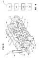
- mold
- casting
- pattern
- mold cavity
- molten material
- Prior art date
- Legal status (The legal status is an assumption and is not a legal conclusion. Google has not performed a legal analysis and makes no representation as to the accuracy of the status listed.)
- Withdrawn
Links
Images



Classifications
-
- B—PERFORMING OPERATIONS; TRANSPORTING
- B22—CASTING; POWDER METALLURGY
- B22D—CASTING OF METALS; CASTING OF OTHER SUBSTANCES BY THE SAME PROCESSES OR DEVICES
- B22D27/00—Treating the metal in the mould while it is molten or ductile ; Pressure or vacuum casting
- B22D27/04—Influencing the temperature of the metal, e.g. by heating or cooling the mould
-
- B—PERFORMING OPERATIONS; TRANSPORTING
- B22—CASTING; POWDER METALLURGY
- B22C—FOUNDRY MOULDING
- B22C7/00—Patterns; Manufacture thereof so far as not provided for in other classes
- B22C7/02—Lost patterns
-
- B—PERFORMING OPERATIONS; TRANSPORTING
- B22—CASTING; POWDER METALLURGY
- B22C—FOUNDRY MOULDING
- B22C9/00—Moulds or cores; Moulding processes
- B22C9/02—Sand moulds or like moulds for shaped castings
- B22C9/04—Use of lost patterns
Definitions
- the invention relates to casting and more particularly to a casting method and mold design for optimization of material properties of a casting, wherein the optimization is accomplished through control of a cooling rate of the casting.
- the casting apparatus comprises a first mold pattern for forming a first mold cavity for receiving a molten material therein; and a second mold pattern positioned adjacent at least a portion of said first mold pattern, said second mold pattern forming a second mold cavity for receiving the molten material therein, wherein the molten material in the second mold cavity controls a cooling rate of the molten material in the portion of the first mold cavity.
- a mold for casting comprises a mold having a first mold cavity and a second mold cavity formed therein and adapted to receive a molten material, the second mold cavity formed adjacent at least a portion of the first mold cavity, wherein the molten material received in the second mold cavity controls a cooling rate of the molten material received in the portion of the first mold cavity adjacent the second mold cavity.
- the invention also provides a method of controlling the cooling rate of molten material in a casting process that comprises the steps of providing a first mold pattern for forming a first mold cavity for receiving a molten material; providing a second mold pattern for forming a second mold cavity for receiving a molten material; positioning the second mold pattern adjacent at least a portion of the first mold pattern; and introducing molten material into the first mold cavity and the second mold cavity, wherein the molten material in the second mold cavity controls the cooling rate of the molten material in the portion of the first mold cavity.
- the apparatus and method of this invention are useful in a casting process.
- the apparatus and method are particularly useful in the casting of engine components such as engine blocks, cylinder heads, and complex transmission components, for example.
- Fig. 1 is a top plan view of a casting apparatus known in the art
- Fig. 2 is a graphical representation of temperature versus time data taken at three points along a crankshaft produced using the prior art casting apparatus of Fig. 1;
- Fig. 3 is a top plan view of a crankshaft made with the prior art casting apparatus of Fig. 1 and showing variations in Brinell hardness along a length of the crankshaft;
- Fig. 4 is a top plan view of an casting apparatus according to an embodiment of the invention.
- Fig. 5 is a perspective view of the casting apparatus of Fig. 4;
- Fig. 6 is a graphical representation of temperature versus time taken at three points along a crankshaft produced using the casting apparatus of Fig. 4;
- Fig. 7 is a top plan view of a crankshaft made with the casting apparatus of Fig. 4 and showing the Brinell hardness along the length of the crankshaft;
- Fig. 8 is a block diagram illustrating a method according to one embodiment of the invention.
- Fig. 1 shows a casting apparatus 10 according to the prior art.
- the casting apparatus 10 is a casting pattern for a mold (not shown) as used in known casting processes such as investment casting, sand casting, permanent mold casting, and die casting, for example.
- the casting apparatus 10 includes a pair of mold patterns 12, a gate 14, and risers 16.
- the mold patterns 12 include a flange 18, a body portion 20, and a stem 22.
- the mold patterns 12 have a shape substantially similar to a desired cast object.
- Fig. 1 shows the mold patterns 12 with a shape substantially similar to a crankshaft 24 as shown in Fig. 3. It is understood that the mold patterns 12 may have the shape of any desired cast object, such as engine blocks, cylinder heads, complex transmission components, and the like, for example.
- the gate 14 forms a conduit (not shown) in the mold that includes an inlet 26 to provide fluid communication with the mold patterns 12 and the risers 16.
- Fig. 1 shows the gate 14 located near the bottom of the casting apparatus 10. It is understood that the gate 14 may be any size or shape and the gate 14 may be located in other areas of the casting apparatus 10, as desired.
- the risers 16 are adapted to form reservoirs (not shown) that militate against the formation of cavities or voids in the desired cast object due to shrinkage of a molten material (not shown) during a cooling thereof.
- Fig. 1 shows a pair of the risers 16 with one of the risers 16 associated with each of the mold patterns 12. It is understood that any shape, size, location, and number of risers may be used, so long as an adequate amount of molten material is provided in the risers 16 to militate against the formation of cavities or voids in the cast object. It is further understood that the molten material may be any metal or non-metal, as desired.
- the casting apparatus 10 including the cavities formed by the mold patterns 12, is filled with the molten material through the conduit formed by the inlet 26 of the gate 14.
- the cavities and the conduit are formed in a sand mold.
- the molten material flows through the casting apparatus 10, filling the mold patterns 12 and the risers 16.
- the molten material is allowed to cool. Because metals are less dense in the liquid state than in the solid state, the volume occupied by the desired cast object will decrease as it cools. Thus, formation of cavities or voids is possible, generally at the last point to solidify.
- the risers 16 militate against the formation of cavities or voids in the desired cast object by providing additional molten material to the mold patterns 12. Therefore, as the molten material solidifies and shrinks, any cavities or voids that form do so in the risers 16 and not in the desired cast object.
- the mold is opened or removed from the cast object. Hardened material from the cavities formed by the gate 14 and the risers 16 is attached to the desired cast object. The hardened material from the gate 14 and the risers 16 is removed from the desired cast object using methods known in the art, and then discarded or recycled.
- Fig. 2 shows a graph 27 of temperature versus time data for a casting produced from the casting apparatus of Fig. 1.
- the graph 27 includes a temperature axis 28 (the y-axis), a time axis 30 (the x-axis), a flange line 32, a body portion line 34, a stem line 36, a shakeout line 38, and a eutectoid line 40.
- the flange line 32, the body portion line 34, and the stem line 36 represent a plot of temperature versus time measurements as measured by thermocouples (not shown) located at the flange 18, the body portion 20, and the stem 22, respectively.
- the thermocouples measure the temperature of the molten material during solidification, cooling, and shakeout periods.
- the shakeout line 38 graphically represents the time period when the crankshaft 24 is removed from the mold.
- the shakeout line 38 is shown at a time between one hundred (100) minutes and one hundred ten (110) minutes. It is understood that that shakeout line 38 can represent any desired time period based on the size or shape of the desired cast object, the temperature range of the material used to make the desired cast object, or other similar factors.
- the eutectoid line 40 graphically represents the temperature at which eutectoid transformation occurs. Eutectoid transformation occurs in a reaction wherein, upon cooling, one solid phase transforms isothermally and reversibly into two new solid phases that are intimately mixed.
- Fig. 2 shows the eutectoid line 40 at a temperature of approximately 700 degrees Celsius. It is understood that the temperature at which eutectoid transformation occurs will vary based on the properties of the materials used to cast the desired cast object. Accordingly, the eutectoid line 40 may be at other temperatures, depending upon the material used.
- alloys such as aluminum for example, do not go through a eutectoid transformation; however, a rate of solidification or rate of freezing may be controlled to affect the alloy's strength by altering a grain size, a dendrite arm spacing, or other similar characteristic of the alloy, as desired.
- the flange line 32, the body portion line 34, and the stem line 36 cross the shakeout line 38 at the same time, and the different parts of the crankshaft 24 represented continue to cool at different rates.
- the flange line 32, the body portion line 34, and the stem line 36 cross the eutectoid line 40 at different times.
- the flange line 32 crosses the eutectoid line 40 at a time between one hundred (100) minutes and one hundred ten (110) minutes, which is after the shakeout period.
- the body portion line 34 crosses the eutectoid line 40 at a time between sixty (60) minutes and seventy (70) minutes, which is before the shakeout period.
- the stem line 36 crosses the eutectoid line 40 at a time between forty (40) minutes and fifty (50) minutes, which is also before the shakeout period. It is understood that that the flange line 32, the body portion line 34, and the stem line 36 may cross the eutectoid line 40 at any time based on the size or shape of the desired cast object, the temperature range or properties of the material used to make the desired cast object, the casting process used, or other similar factors. Because the flange line 32, the body portion line 34, and the stem line 36 illustrate different cooling rates for different parts of the crankshaft 24 the material properties from one part of the crankshaft 24 to another vary.
- Fig. 3 shows a hardness distribution of the crankshaft 24 formed using the casting apparatus 10 known in the art.
- the Brinell hardness scale was used to show the non-uniform hardness distribution of the crankshaft 24.
- the Brinell hardness scale characterizes the indentation hardness of materials through the scale of penetration of an indenter.
- the typical test uses a 10 mm diameter steel ball as the indenter with a 3,000 kgf (29 kN) force. For softer materials, a smaller force is used; for harder materials, a tungsten carbide ball is substituted for the steel ball.
- BHN Brinell Harness Number
- the crankshaft 24 includes a stem portion 42, a lower body portion 44, an upper body portion 46, and a flange portion 48.
- the stem portion 42 and the lower body portion 44 have BHNs between 141.0 and 220.03.
- the upper body portion 46 and flange portion 48 have BHNs between 273.0 and 326.0.
- the difference in hardness, represented by BHNs is an effect of the stem portion 42 and the lower body portion 44 cooling at different rates than the upper body portion 46 and flange portion 48.
- the difference in cooling rates from one region of a desired cast object to another region results in different rates of eutectoid transformation. Different rates of eutectoid transformation results in the desired cast object having different material properties from one region thereof to another.
- Figs. 4 and 5 show a casting apparatus 60 according to an embodiment of the invention.
- the casting apparatus 60 is a casting pattern for a mold (not shown) that may be used in any known casting process such as investment casting, sand casting, permanent mold casting, and die casting, for example.
- the casting apparatus 60 includes a pair of first mold patterns 62, a second mold pattern 64, a gate 66, and risers 68. It is understood that more or fewer mold patterns 62, 64 can be used as desired.
- the first mold patterns 62 include a flange 70, a body portion 72, and a stem 74.
- the first mold patterns 62 are adapted to form a mold cavity (not shown) in the mold which is in fluid communication with a mold cavity (not shown) formed by the gate 66, and the risers 68.
- the first mold patterns 62 have a shape substantially similar to a desired cast object.
- the first mold patterns 62 have a shape substantially similar to a crankshaft 76, as shown in Fig. 7. It is understood that the first mold patterns 62 may have the shape of any desired cast object such as engine blocks, cylinder heads, complex transmission components, and the like, for example.
- the second mold pattern 64 includes an inner wall 78 and an outer wall 80.
- the second mold pattern 64 is adapted to form a mold cavity (not shown) which is in fluid communication with a conduit (not shown) which is part of the cavity formed by the gate 66, and the risers 68.
- the inner wall 78 and the outer wall 80 of the second mold pattern 64 are configured to circumscribe the two-dimensional shape of the profile of the stem 74 of the first mold patterns 62.
- the term circumscribe as used herein means that the inner wall 78 and the outer wall 80 of the second mold pattern 64 at least partially surround, in close proximity to but without actually contacting, the first mold pattern 62.
- the inner wall 78 of the second mold pattern 64 may be any shape or configuration desired such as the shape of a particular portion of the first mold patterns 62, or any geometric shape, for example. It is also understood that the inner wall could circumscribe a particular portion of the first mold pattern 62 three-dimensionally.
- the outer wall 80 may be any shape or configuration, as desired.
- the second mold pattern 64 may also have a shape substantially similar to another desired cast object. It is further understood that the second mold pattern 64 may be positioned at any distance from the first mold pattern 62, as desired.
- the exact configuration and position of the second mold pattern 64 will depend on the size, shape, and surface area of the first mold patterns 62, the desired cooling rate of molten material filling the cavity formed by the first mold patterns 62, and the like, for example. As shown, the second mold pattern 64 is positioned adjacent the stem 74 of the first mold patterns 62. It is understood that the second mold pattern 64 may be positioned adjacent any portion of the first mold patterns 62 such as the flange 70, the body portion 72, or any combination of the portions of the first mold patterns 62, as desired.
- the gate 66 forms the conduit that includes an inlet 82 to provide fluid communication with the first mold patterns 62, the second mold pattern 64, and the risers 68.
- the gate 66 is located near the bottom of the casting apparatus 60. It is understood that the gate 66 may be any gate known in the art.
- the gate 66 may be any size or shape and the gate 66 may be located anywhere on the casting apparatus 60, as desired.
- the risers 68 are adapted to form reservoirs (not shown) that militate against the formation of cavities or voids in the desired cast object due to shrinkage of a molten material (not shown) during a cooling thereof.
- Figs. 4 and 5 show a pair of risers 68 with one of the risers 68 associated with each of the first mold patterns 62. It is understood that any shape, size, location, and number of the risers 68 may be used so long as an adequate amount of molten material is provided in the risers 68 to militate against the formation of cavities and voids in the desired cast object. It is further understood that the molten material may be any metal or non-metal, as desired.
- the casting apparatus 60 including the cavities formed by the first mold patterns 62 and the second mold pattern 64, are filled with the molten material through the conduit formed by the inlet 82 of the gate 66.
- the molten material flows through the casting apparatus 60 filling the mold cavities formed by the first mold patterns 62, the second mold pattern 64, and the risers 68.
- the casting apparatus 60 and the desired cast object are allowed to cool. Because metals are less dense in the liquid state than in the solid state, the volume occupied by the desired cast object will decrease as it cools. Thus, formation of cavities or voids is possible, generally at the last point to solidify.
- the risers 68 militate against the formation of cavities or voids in the desired cast object by providing additional molten material to the cavity formed by the first mold patterns 62. Therefore, as the molten material solidifies and shrinks any cavities or voids that form, do so in the risers 68 and not in the desired cast object.
- a cooling rate of the portion of the cast object adjacent the mold cavity formed by the second mold pattern 64 is controlled by the heat radiating from the molten material in the mold cavity formed by the second mold pattern 64. If the portion of the cast object formed in the cavity formed by the first mold patterns 62 adjacent to the cavity formed by the second mold pattern 64 would normally cool faster than the other portions of the cast object, the cooling rate of the cast object formed in the cavity formed by the first mold patterns 62 is decreased by the radiating heat. It is understood that a plurality of mold patterns may be used to control the cooling rate of the first mold pattern 64 without departing from the scope of the invention.
- the mold is opened and the desired cast object is removed.
- Hardened material from the cavities or conduits formed by the gate 66, the risers 68, and the second mold pattern 64 is attached to the desired cast object.
- the hardened material is removed from the desired cast object using methods known in the art, and then discarded or recycled.
- Fig. 6 shows a graph 83 of temperature versus time data for a casting produced from the casting apparatus 60.
- the graph 83 includes a temperature axis 84 (the y-axis), a time axis 86 (the x-axis), a flange line 88, a body portion line 90, a stem line 92, a shakeout line 94, and a eutectoid line 96.
- the flange line 88, the body portion line 90, and the stem line 92 represent a plot of temperature versus time measurements as measured by thermocouples (not shown) located at the flange 70, the body portion 72, and the stem 74, respectively.
- the thermocouples measure the temperature of the molten material during solidification, cooling, and shakeout periods.
- the shakeout line 94 graphically represents the time period when the crankshaft 76 is removed from the mold. For purposes of illustration, the shakeout line 94 is shown at a time between one hundred (100) minutes and one hundred ten (110) minutes. It is understood that that shakeout line 94 may represent any desired time period based on the size or shape of the desired cast object, the temperature range of the material used to make the desired cast object, or other similar factors.
- the eutectoid line 96 graphically represents the temperature at which eutectoid transformation occurs. Eutectoid transformation occurs in a reaction wherein, upon cooling, one solid phase transforms isothermally and reversibly into two new solid phases that are intimately mixed.
- Fig. 6 shows the eutectoid line 96 at a temperature of approximately 700 degrees Celsius. It is understood that the temperature at which eutectoid transformation occurs will vary based on the properties of the materials used to cast the desired cast object. Accordingly, the eutectoid line 96 may be at other temperatures depending upon the material used.
- alloys such as aluminum for example, do not go through a eutectoid transformation; however, a rate of solidification or rate of freezing may be controlled to affect the alloy's strength by altering a grain size, a dendrite arm spacing, or other similar characteristic of the alloy, as desired.
- the flange line 88, the body portion line 90, and the stem line 92 have substantially similar cooling rates and cross the shakeout line 94 at substantially the same time. Because the flange line 88, the body portion line 90, and the stem line 92 have substantially similar cooling rates, the flange line 88, the body portion line 90, and the stem line 92 cross the eutectoid line 96 at the substantially same rate and time. In the embodiment shown, the flange line 88, the body portion line 90, and the stem line 92 all cross the eutectoid line 96 at the same rate, at a time between one hundred five (105) minutes and one hundred ten (115) minutes, which is after the shakeout period.
- the material properties from one portion to another within the casting will be substantially the same. It is understood that that the flange line 88, the body portion line 90, and the stem line 92 may cross the eutectoid line 96 at other times based on the size or shape of the desired cast object, the temperature or properties of the molten material used to make the desired cast object, the casting process used, or other similar factors.
- Fig. 7 shows a hardness distribution of the crankshaft 76 formed using the casting apparatus 60.
- the Brinell hardness scale was used to show the non-uniform hardness distribution of the crankshaft 76. It is understood that there are a number of other hardness tests that may be used to determine the hardness distribution of the desired cast object.
- the crankshaft 76 shown includes a stem portion 98, a lower body portion 100, an upper body portion 102, and a flange portion 104.
- the stem portion 98, the lower body portion 100, the upper body portion 102, and the flange portion 104 all have BHNs between 273.0 and 326.0. This data is used for illustrative purposes to show the consistent material properties and is not intended to limit the scope of the invention.
- the substantially uniform hardness is a result of the stem portion 98, the lower body portion 100, the upper body portion 102, and the flange portion 104 cooling at the substantially same rate.
- the substantial similarity of the cooling rates from one region of the desired cast object to another results in similar times of eutectoid transformation. Similar rates of eutectoid transformation cause the desired cast object to have substantially similar material properties from one portion of the desired cast object to another.
- Fig. 8 schematically illustrates a method 110 of controlling the cooling rate of molten material in a first mold cavity according to one embodiment of the invention.
- the method 110 may be used with any known casting process, such as investment casting, sand casting, permanent mold casting, and die casting, for example.
- a first mold cavity is formed which is adapted to receive a molten material.
- the first mold cavity may be any size or shape as desired to produce a desired cast object.
- the first mold cavity may be the size or shape of a crankshaft, an engine block, a cylinder head, a complex transmission component, and the like, for example.
- a second mold cavity is formed which is adapted to receive a molten material.
- the second mold cavity may be configured to circumscribe the two-dimensional profile of a portion of the first mold cavity. It is understood that second mold cavity may be any shape or configuration desired such as the shape of a particular portion of the first mold cavity, or any geometric shape, for example. It is also understood that the second mold cavity could circumscribe a particular portion of the first mold cavity three-dimensionally.
- the second mold cavity may be any shape or configuration, as desired.
- the second mold cavity may also have a shape substantially similar to another desired cast object. It is further understood that the second mold cavity may be positioned at any distance from the first mold cavity, as desired. The exact configuration and position of the second mold cavity will depend on the size, shape, and surface area of the first mold cavity, as well as the desired cooling rate of the molten material in the first mold cavity.
- the second mold cavity is positioned adjacent a portion of the first mold cavity. It is understood that the second mold cavity may be placed adjacent one side, two sides, or completely surrounding the portion of the first mold cavity.
- a molten material is introduced into the first mold cavity and the second mold cavity, wherein the heat radiating from the second mold cavity controls the cooling rate of the molten material inside the portion of the first mold cavity.
- the cooling rate of the portion of the molten material in the first mold cavity adjacent to the second mold cavity may be controlled so that the portion adjacent to the second mold cavity cools at a substantially similar rate as the remaining portions of the molten material in the first mold cavity.
- the cooling rate of the portion of the molten material in the first mold cavity adjacent to the second mold cavity may be controlled so that the portion adjacent to the second mold cavity cools at a slower rate than the rest of the molten material in the first mold cavity.
Landscapes
- Engineering & Computer Science (AREA)
- Mechanical Engineering (AREA)
- Molds, Cores, And Manufacturing Methods Thereof (AREA)
- Continuous Casting (AREA)
Abstract
Description
- The invention relates to casting and more particularly to a casting method and mold design for optimization of material properties of a casting, wherein the optimization is accomplished through control of a cooling rate of the casting.
- In a casting process, variations in material properties can occur in different regions within a casting. Amongst other reasons, the variations can occur when the different regions of the casting are permitted to cool, and thus solidify, at different rates. Castings having complicated geometries are particularly susceptible to these variations since the cooling rates in the various regions of the casting are geometry dependant. For example, in a region having a high ratio of local surface area to volume, the faster the region will tend to cool. In a region having a low ratio of local surface area to volume, the slower the region will tend to cool. This results in material properties which vary significantly from one region to another region within the casting.
- Such variations in material properties within a casting are often undesirable. The variations can cause problems with machinability or other processing. Issues with product performance can also arise.
- It would be desirable to develop a casting method and mold design for optimization of material properties of a casting.
- Concordant and congruous with the present invention, a casting method and mold design for optimization of material properties of a casting, has surprisingly been discovered.
- In one embodiment, the casting apparatus comprises a first mold pattern for forming a first mold cavity for receiving a molten material therein; and a second mold pattern positioned adjacent at least a portion of said first mold pattern, said second mold pattern forming a second mold cavity for receiving the molten material therein, wherein the molten material in the second mold cavity controls a cooling rate of the molten material in the portion of the first mold cavity.
- In another embodiment, a mold for casting comprises a mold having a first mold cavity and a second mold cavity formed therein and adapted to receive a molten material, the second mold cavity formed adjacent at least a portion of the first mold cavity, wherein the molten material received in the second mold cavity controls a cooling rate of the molten material received in the portion of the first mold cavity adjacent the second mold cavity.
- The invention also provides a method of controlling the cooling rate of molten material in a casting process that comprises the steps of providing a first mold pattern for forming a first mold cavity for receiving a molten material; providing a second mold pattern for forming a second mold cavity for receiving a molten material; positioning the second mold pattern adjacent at least a portion of the first mold pattern; and introducing molten material into the first mold cavity and the second mold cavity, wherein the molten material in the second mold cavity controls the cooling rate of the molten material in the portion of the first mold cavity.
- The apparatus and method of this invention are useful in a casting process. The apparatus and method are particularly useful in the casting of engine components such as engine blocks, cylinder heads, and complex transmission components, for example.
- The above, as well as other advantages of the present invention, will become readily apparent to those skilled in the art from the following detailed description of a preferred embodiment when considered in the light of the accompanying drawings in which:
- Fig. 1 is a top plan view of a casting apparatus known in the art;
- Fig. 2 is a graphical representation of temperature versus time data taken at three points along a crankshaft produced using the prior art casting apparatus of Fig. 1;
- Fig. 3 is a top plan view of a crankshaft made with the prior art casting apparatus of Fig. 1 and showing variations in Brinell hardness along a length of the crankshaft;
- Fig. 4 is a top plan view of an casting apparatus according to an embodiment of the invention;
- Fig. 5 is a perspective view of the casting apparatus of Fig. 4;
- Fig. 6 is a graphical representation of temperature versus time taken at three points along a crankshaft produced using the casting apparatus of Fig. 4;
- Fig. 7 is a top plan view of a crankshaft made with the casting apparatus of Fig. 4 and showing the Brinell hardness along the length of the crankshaft; and
- Fig. 8 is a block diagram illustrating a method according to one embodiment of the invention.
- The following detailed description and appended drawings describe and illustrate various exemplary embodiments of the invention. The description and drawings serve to enable one skilled in the art to make and use the invention, and are not intended to limit the scope of the invention in any manner. In respect of the methods disclosed, the steps presented are exemplary in nature, and thus, the order of the steps is not necessary or critical.
- Fig. 1 shows a
casting apparatus 10 according to the prior art. Thecasting apparatus 10 is a casting pattern for a mold (not shown) as used in known casting processes such as investment casting, sand casting, permanent mold casting, and die casting, for example. Thecasting apparatus 10 includes a pair ofmold patterns 12, agate 14, andrisers 16. - The
mold patterns 12 include aflange 18, abody portion 20, and astem 22. Themold patterns 12 have a shape substantially similar to a desired cast object. Fig. 1 shows themold patterns 12 with a shape substantially similar to acrankshaft 24 as shown in Fig. 3. It is understood that themold patterns 12 may have the shape of any desired cast object, such as engine blocks, cylinder heads, complex transmission components, and the like, for example. - The
gate 14 forms a conduit (not shown) in the mold that includes aninlet 26 to provide fluid communication with themold patterns 12 and therisers 16. Fig. 1 shows thegate 14 located near the bottom of thecasting apparatus 10. It is understood that thegate 14 may be any size or shape and thegate 14 may be located in other areas of thecasting apparatus 10, as desired. - The
risers 16 are adapted to form reservoirs (not shown) that militate against the formation of cavities or voids in the desired cast object due to shrinkage of a molten material (not shown) during a cooling thereof. Fig. 1 shows a pair of therisers 16 with one of therisers 16 associated with each of themold patterns 12. It is understood that any shape, size, location, and number of risers may be used, so long as an adequate amount of molten material is provided in therisers 16 to militate against the formation of cavities or voids in the cast object. It is further understood that the molten material may be any metal or non-metal, as desired. - In use, the
casting apparatus 10, including the cavities formed by themold patterns 12, is filled with the molten material through the conduit formed by theinlet 26 of thegate 14. In sand casting, for example, the cavities and the conduit are formed in a sand mold. The molten material flows through thecasting apparatus 10, filling themold patterns 12 and therisers 16. - Once the mold cavity formed by the
patterns 12 has been filled, the molten material is allowed to cool. Because metals are less dense in the liquid state than in the solid state, the volume occupied by the desired cast object will decrease as it cools. Thus, formation of cavities or voids is possible, generally at the last point to solidify. Therisers 16 militate against the formation of cavities or voids in the desired cast object by providing additional molten material to themold patterns 12. Therefore, as the molten material solidifies and shrinks, any cavities or voids that form do so in therisers 16 and not in the desired cast object. Once the desired cast object has solidified and sufficiently cooled, the mold is opened or removed from the cast object. Hardened material from the cavities formed by thegate 14 and therisers 16 is attached to the desired cast object. The hardened material from thegate 14 and therisers 16 is removed from the desired cast object using methods known in the art, and then discarded or recycled. - Fig. 2 shows a
graph 27 of temperature versus time data for a casting produced from the casting apparatus of Fig. 1. Thegraph 27 includes a temperature axis 28 (the y-axis), a time axis 30 (the x-axis), aflange line 32, abody portion line 34, astem line 36, ashakeout line 38, and aeutectoid line 40. - The
flange line 32, thebody portion line 34, and thestem line 36 represent a plot of temperature versus time measurements as measured by thermocouples (not shown) located at theflange 18, thebody portion 20, and thestem 22, respectively. The thermocouples measure the temperature of the molten material during solidification, cooling, and shakeout periods. - The
shakeout line 38 graphically represents the time period when thecrankshaft 24 is removed from the mold. Theshakeout line 38 is shown at a time between one hundred (100) minutes and one hundred ten (110) minutes. It is understood that thatshakeout line 38 can represent any desired time period based on the size or shape of the desired cast object, the temperature range of the material used to make the desired cast object, or other similar factors. - The
eutectoid line 40 graphically represents the temperature at which eutectoid transformation occurs. Eutectoid transformation occurs in a reaction wherein, upon cooling, one solid phase transforms isothermally and reversibly into two new solid phases that are intimately mixed. Fig. 2 shows theeutectoid line 40 at a temperature of approximately 700 degrees Celsius. It is understood that the temperature at which eutectoid transformation occurs will vary based on the properties of the materials used to cast the desired cast object. Accordingly, theeutectoid line 40 may be at other temperatures, depending upon the material used. It is understood that some alloys, such as aluminum for example, do not go through a eutectoid transformation; however, a rate of solidification or rate of freezing may be controlled to affect the alloy's strength by altering a grain size, a dendrite arm spacing, or other similar characteristic of the alloy, as desired. - The
flange line 32, thebody portion line 34, and thestem line 36 cross theshakeout line 38 at the same time, and the different parts of thecrankshaft 24 represented continue to cool at different rates. Theflange line 32, thebody portion line 34, and thestem line 36 cross theeutectoid line 40 at different times. Theflange line 32 crosses theeutectoid line 40 at a time between one hundred (100) minutes and one hundred ten (110) minutes, which is after the shakeout period. Thebody portion line 34 crosses theeutectoid line 40 at a time between sixty (60) minutes and seventy (70) minutes, which is before the shakeout period. Thestem line 36 crosses theeutectoid line 40 at a time between forty (40) minutes and fifty (50) minutes, which is also before the shakeout period. It is understood that that theflange line 32, thebody portion line 34, and thestem line 36 may cross theeutectoid line 40 at any time based on the size or shape of the desired cast object, the temperature range or properties of the material used to make the desired cast object, the casting process used, or other similar factors. Because theflange line 32, thebody portion line 34, and thestem line 36 illustrate different cooling rates for different parts of thecrankshaft 24 the material properties from one part of thecrankshaft 24 to another vary. - Fig. 3 shows a hardness distribution of the
crankshaft 24 formed using thecasting apparatus 10 known in the art. The Brinell hardness scale was used to show the non-uniform hardness distribution of thecrankshaft 24. The Brinell hardness scale characterizes the indentation hardness of materials through the scale of penetration of an indenter. The typical test uses a 10 mm diameter steel ball as the indenter with a 3,000 kgf (29 kN) force. For softer materials, a smaller force is used; for harder materials, a tungsten carbide ball is substituted for the steel ball. The hardness is calculated using the following equation: Brinell Harness Number (BHN) = P/[Π*D*(D-√(D2-d2))], where P is the force applied, D is the diameter of the indenter, and d is the diameter of the indentation. It is understood that there are a number of other hardness tests that may be used to determine the hardness distribution of the desired cast object. - The
crankshaft 24 includes astem portion 42, alower body portion 44, anupper body portion 46, and aflange portion 48. Thestem portion 42 and thelower body portion 44 have BHNs between 141.0 and 220.03. Theupper body portion 46 andflange portion 48 have BHNs between 273.0 and 326.0. The difference in hardness, represented by BHNs, is an effect of thestem portion 42 and thelower body portion 44 cooling at different rates than theupper body portion 46 andflange portion 48. As described above, the difference in cooling rates from one region of a desired cast object to another region results in different rates of eutectoid transformation. Different rates of eutectoid transformation results in the desired cast object having different material properties from one region thereof to another. - Figs. 4 and 5 show a
casting apparatus 60 according to an embodiment of the invention. Thecasting apparatus 60 is a casting pattern for a mold (not shown) that may be used in any known casting process such as investment casting, sand casting, permanent mold casting, and die casting, for example. Thecasting apparatus 60 includes a pair offirst mold patterns 62, asecond mold pattern 64, agate 66, andrisers 68. It is understood that more orfewer mold patterns - The
first mold patterns 62 include aflange 70, abody portion 72, and astem 74. Thefirst mold patterns 62 are adapted to form a mold cavity (not shown) in the mold which is in fluid communication with a mold cavity (not shown) formed by thegate 66, and therisers 68. Thefirst mold patterns 62 have a shape substantially similar to a desired cast object. In the embodiment shown, thefirst mold patterns 62 have a shape substantially similar to acrankshaft 76, as shown in Fig. 7. It is understood that thefirst mold patterns 62 may have the shape of any desired cast object such as engine blocks, cylinder heads, complex transmission components, and the like, for example. - In the embodiment shown, the
second mold pattern 64 includes aninner wall 78 and anouter wall 80. Thesecond mold pattern 64 is adapted to form a mold cavity (not shown) which is in fluid communication with a conduit (not shown) which is part of the cavity formed by thegate 66, and therisers 68. Theinner wall 78 and theouter wall 80 of thesecond mold pattern 64 are configured to circumscribe the two-dimensional shape of the profile of thestem 74 of thefirst mold patterns 62. The term circumscribe as used herein means that theinner wall 78 and theouter wall 80 of thesecond mold pattern 64 at least partially surround, in close proximity to but without actually contacting, thefirst mold pattern 62. It is understood that theinner wall 78 of thesecond mold pattern 64 may be any shape or configuration desired such as the shape of a particular portion of thefirst mold patterns 62, or any geometric shape, for example. It is also understood that the inner wall could circumscribe a particular portion of thefirst mold pattern 62 three-dimensionally. Theouter wall 80 may be any shape or configuration, as desired. Thesecond mold pattern 64 may also have a shape substantially similar to another desired cast object. It is further understood that thesecond mold pattern 64 may be positioned at any distance from thefirst mold pattern 62, as desired. The exact configuration and position of thesecond mold pattern 64 will depend on the size, shape, and surface area of thefirst mold patterns 62, the desired cooling rate of molten material filling the cavity formed by thefirst mold patterns 62, and the like, for example. As shown, thesecond mold pattern 64 is positioned adjacent thestem 74 of thefirst mold patterns 62. It is understood that thesecond mold pattern 64 may be positioned adjacent any portion of thefirst mold patterns 62 such as theflange 70, thebody portion 72, or any combination of the portions of thefirst mold patterns 62, as desired. - The
gate 66 forms the conduit that includes aninlet 82 to provide fluid communication with thefirst mold patterns 62, thesecond mold pattern 64, and therisers 68. In the embodiment shown, thegate 66 is located near the bottom of thecasting apparatus 60. It is understood that thegate 66 may be any gate known in the art. Thegate 66 may be any size or shape and thegate 66 may be located anywhere on thecasting apparatus 60, as desired. - The
risers 68 are adapted to form reservoirs (not shown) that militate against the formation of cavities or voids in the desired cast object due to shrinkage of a molten material (not shown) during a cooling thereof. Figs. 4 and 5 show a pair ofrisers 68 with one of therisers 68 associated with each of thefirst mold patterns 62. It is understood that any shape, size, location, and number of therisers 68 may be used so long as an adequate amount of molten material is provided in therisers 68 to militate against the formation of cavities and voids in the desired cast object. It is further understood that the molten material may be any metal or non-metal, as desired. - In use, the
casting apparatus 60, including the cavities formed by thefirst mold patterns 62 and thesecond mold pattern 64, are filled with the molten material through the conduit formed by theinlet 82 of thegate 66. The molten material flows through thecasting apparatus 60 filling the mold cavities formed by thefirst mold patterns 62, thesecond mold pattern 64, and therisers 68. - Once the mold cavities have been filled, the
casting apparatus 60 and the desired cast object are allowed to cool. Because metals are less dense in the liquid state than in the solid state, the volume occupied by the desired cast object will decrease as it cools. Thus, formation of cavities or voids is possible, generally at the last point to solidify. Therisers 68 militate against the formation of cavities or voids in the desired cast object by providing additional molten material to the cavity formed by thefirst mold patterns 62. Therefore, as the molten material solidifies and shrinks any cavities or voids that form, do so in therisers 68 and not in the desired cast object. A cooling rate of the portion of the cast object adjacent the mold cavity formed by thesecond mold pattern 64 is controlled by the heat radiating from the molten material in the mold cavity formed by thesecond mold pattern 64. If the portion of the cast object formed in the cavity formed by thefirst mold patterns 62 adjacent to the cavity formed by thesecond mold pattern 64 would normally cool faster than the other portions of the cast object, the cooling rate of the cast object formed in the cavity formed by thefirst mold patterns 62 is decreased by the radiating heat. It is understood that a plurality of mold patterns may be used to control the cooling rate of thefirst mold pattern 64 without departing from the scope of the invention. - Once the desired cast object has solidified and sufficiently cooled the mold is opened and the desired cast object is removed. Hardened material from the cavities or conduits formed by the
gate 66, therisers 68, and thesecond mold pattern 64 is attached to the desired cast object. The hardened material is removed from the desired cast object using methods known in the art, and then discarded or recycled. - Fig. 6 shows a
graph 83 of temperature versus time data for a casting produced from thecasting apparatus 60. Thegraph 83 includes a temperature axis 84 (the y-axis), a time axis 86 (the x-axis), aflange line 88, abody portion line 90, astem line 92, ashakeout line 94, and aeutectoid line 96. - The
flange line 88, thebody portion line 90, and thestem line 92 represent a plot of temperature versus time measurements as measured by thermocouples (not shown) located at theflange 70, thebody portion 72, and thestem 74, respectively. The thermocouples measure the temperature of the molten material during solidification, cooling, and shakeout periods. - The
shakeout line 94 graphically represents the time period when thecrankshaft 76 is removed from the mold. For purposes of illustration, theshakeout line 94 is shown at a time between one hundred (100) minutes and one hundred ten (110) minutes. It is understood that thatshakeout line 94 may represent any desired time period based on the size or shape of the desired cast object, the temperature range of the material used to make the desired cast object, or other similar factors. - The
eutectoid line 96 graphically represents the temperature at which eutectoid transformation occurs. Eutectoid transformation occurs in a reaction wherein, upon cooling, one solid phase transforms isothermally and reversibly into two new solid phases that are intimately mixed. Fig. 6 shows theeutectoid line 96 at a temperature of approximately 700 degrees Celsius. It is understood that the temperature at which eutectoid transformation occurs will vary based on the properties of the materials used to cast the desired cast object. Accordingly, theeutectoid line 96 may be at other temperatures depending upon the material used. It is understood that some alloys, such as aluminum for example, do not go through a eutectoid transformation; however, a rate of solidification or rate of freezing may be controlled to affect the alloy's strength by altering a grain size, a dendrite arm spacing, or other similar characteristic of the alloy, as desired. - The
flange line 88, thebody portion line 90, and thestem line 92 have substantially similar cooling rates and cross theshakeout line 94 at substantially the same time. Because theflange line 88, thebody portion line 90, and thestem line 92 have substantially similar cooling rates, theflange line 88, thebody portion line 90, and thestem line 92 cross theeutectoid line 96 at the substantially same rate and time. In the embodiment shown, theflange line 88, thebody portion line 90, and thestem line 92 all cross theeutectoid line 96 at the same rate, at a time between one hundred five (105) minutes and one hundred ten (115) minutes, which is after the shakeout period. As a result of the substantially similar cooling rates and the substantially similar rates of eutectoid transformation, the material properties from one portion to another within the casting will be substantially the same. It is understood that that theflange line 88, thebody portion line 90, and thestem line 92 may cross theeutectoid line 96 at other times based on the size or shape of the desired cast object, the temperature or properties of the molten material used to make the desired cast object, the casting process used, or other similar factors. - Fig. 7 shows a hardness distribution of the
crankshaft 76 formed using thecasting apparatus 60. The Brinell hardness scale was used to show the non-uniform hardness distribution of thecrankshaft 76. It is understood that there are a number of other hardness tests that may be used to determine the hardness distribution of the desired cast object. - The
crankshaft 76 shown includes astem portion 98, alower body portion 100, anupper body portion 102, and aflange portion 104. In the embodiment shown, thestem portion 98, thelower body portion 100, theupper body portion 102, and theflange portion 104 all have BHNs between 273.0 and 326.0. This data is used for illustrative purposes to show the consistent material properties and is not intended to limit the scope of the invention. The substantially uniform hardness is a result of thestem portion 98, thelower body portion 100, theupper body portion 102, and theflange portion 104 cooling at the substantially same rate. As described above, the substantial similarity of the cooling rates from one region of the desired cast object to another results in similar times of eutectoid transformation. Similar rates of eutectoid transformation cause the desired cast object to have substantially similar material properties from one portion of the desired cast object to another. - Fig. 8 schematically illustrates a
method 110 of controlling the cooling rate of molten material in a first mold cavity according to one embodiment of the invention. Themethod 110 may be used with any known casting process, such as investment casting, sand casting, permanent mold casting, and die casting, for example. - In a
first step 112, a first mold cavity is formed which is adapted to receive a molten material. The first mold cavity may be any size or shape as desired to produce a desired cast object. The first mold cavity may be the size or shape of a crankshaft, an engine block, a cylinder head, a complex transmission component, and the like, for example. - In a
second step 114, a second mold cavity is formed which is adapted to receive a molten material. The second mold cavity may be configured to circumscribe the two-dimensional profile of a portion of the first mold cavity. It is understood that second mold cavity may be any shape or configuration desired such as the shape of a particular portion of the first mold cavity, or any geometric shape, for example. It is also understood that the second mold cavity could circumscribe a particular portion of the first mold cavity three-dimensionally. The second mold cavity may be any shape or configuration, as desired. The second mold cavity may also have a shape substantially similar to another desired cast object. It is further understood that the second mold cavity may be positioned at any distance from the first mold cavity, as desired. The exact configuration and position of the second mold cavity will depend on the size, shape, and surface area of the first mold cavity, as well as the desired cooling rate of the molten material in the first mold cavity. - In a
third step 116, the second mold cavity is positioned adjacent a portion of the first mold cavity. It is understood that the second mold cavity may be placed adjacent one side, two sides, or completely surrounding the portion of the first mold cavity. - In a
fourth step 118, a molten material is introduced into the first mold cavity and the second mold cavity, wherein the heat radiating from the second mold cavity controls the cooling rate of the molten material inside the portion of the first mold cavity. The cooling rate of the portion of the molten material in the first mold cavity adjacent to the second mold cavity may be controlled so that the portion adjacent to the second mold cavity cools at a substantially similar rate as the remaining portions of the molten material in the first mold cavity. Alternatively, the cooling rate of the portion of the molten material in the first mold cavity adjacent to the second mold cavity may be controlled so that the portion adjacent to the second mold cavity cools at a slower rate than the rest of the molten material in the first mold cavity. - From the foregoing description, one ordinarily skilled in the art can easily ascertain the essential characteristics of this invention and, without departing from the spirit and scope thereof, can make various changes and modifications to the invention to adapt it to various usages and conditions.
Claims (20)
- A casting apparatus (60) comprising:a first mold pattern (62) for forming a first mold cavity for receiving a molten material therein, anda second mold pattern (64) positioned adjacent at least a portion of said first mold pattern (62), said second mold pattern (64) forming a second mold cavity for receiving the molten material therein, wherein the molten material in the second mold cavity controls a cooling rate of the molten material in the portion of the first mold cavity.
- The apparatus of Claim 1, wherein said first mold pattern (62) and said second mold pattern (64) are patterns for a sand casting process.
- The apparatus (60) of Claim 1, wherein said first mold pattern (62) and said second mold pattern (64) are patterns for a die casting process.
- The apparatus (60) of Claim 1, wherein said first mold pattern (62) and said second mold pattern (64) are patterns for an investment casting process.
- The apparatus (60) of Claim 1, wherein said first mold pattern (62) and said second mold pattern (64) are patterns for a permanent mold casting process.
- The apparatus (60) of Claim 1, wherein said second mold pattern (64) is adjacent at least one side of said first mold pattern (62).
- The apparatus (60) of Claim 6, wherein said second mold pattern (64) is adjacent two sides of said first mold pattern (62).
- The apparatus (60) of Claim 6, wherein said second mold pattern (64) is adjacent three sides of said first mold pattern (62).
- The apparatus (60) of Claim 1, wherein said second mold pattern (64) surrounds at least a portion of said first mold pattern (62).
- A mold (60) for casting comprising:a mold (62, 64) having a first mold cavity and a second mold cavity formed therein and adapted to receive a molten material, the second mold cavity formed adjacent at least a portion of the first mold cavity,wherein the molten material received in the second mold cavity controls a cooling rate of the molten material received in the portion of the first mold cavity adjacent the second mold cavity.
- The mold (60) of Claim 10, wherein said mold (62, 64) is a sand casting mold.
- The mold (60) of Claim 10, wherein said mold (62, 64) is a die casting mold.
- The mold (60) of Claim 10, wherein said mold (62, 64) is an investment casting mold.
- The mold (60) of Claim 10, wherein said mold (62, 64) is a permanent mold casting mold.
- The mold (60) of Claim 10, wherein the second mold cavity is adjacent one side of the first mold cavity.
- The mold (60) of Claim 15, wherein the second mold cavity is adjacent two sides of the first mold cavity.
- The mold (60) of Claim 15, wherein the second mold cavity is adjacent three sides of the first mold cavity.
- The mold (60) of Claim 10, wherein the second mold cavity surrounds at least a portion of the first mold cavity.
- A method (110) of controlling the cooling rate of molten material
in a casting process comprising the steps of:providing a first mold pattern (62) for forming a first mold cavity for receiving a molten material (112);providing a second mold pattern (64) for forming a second mold cavity for receiving a molten material (114);positioning the second mold pattern (64) adjacent at least a portion of the first mold pattern (62), (116); andintroducing molten material into the first mold cavity and the second mold cavity, wherein the molten material in the second mold cavity controls the cooling rate of the molten material in the portion of the first mold cavity (118). - The method (110) of Claim 19, wherein the second mold pattern (64) is positioned adjacent at least one side of the first mold pattern (62).
Applications Claiming Priority (1)
| Application Number | Priority Date | Filing Date | Title |
|---|---|---|---|
| US11/414,806 US20070251664A1 (en) | 2006-05-01 | 2006-05-01 | Casting method and mold design for optimization of material properties of a casting |
Publications (2)
| Publication Number | Publication Date |
|---|---|
| EP1852198A2 true EP1852198A2 (en) | 2007-11-07 |
| EP1852198A3 EP1852198A3 (en) | 2008-10-22 |
Family
ID=38362766
Family Applications (1)
| Application Number | Title | Priority Date | Filing Date |
|---|---|---|---|
| EP07007080A Withdrawn EP1852198A3 (en) | 2006-05-01 | 2007-04-04 | Casting method and mold design for optimization of material properties of a casting |
Country Status (3)
| Country | Link |
|---|---|
| US (1) | US20070251664A1 (en) |
| EP (1) | EP1852198A3 (en) |
| CN (1) | CN101066553A (en) |
Cited By (1)
| Publication number | Priority date | Publication date | Assignee | Title |
|---|---|---|---|---|
| CN105636721A (en) * | 2013-11-14 | 2016-06-01 | 宝马股份公司 | Complex castings and casting methods |
Families Citing this family (2)
| Publication number | Priority date | Publication date | Assignee | Title |
|---|---|---|---|---|
| DE102013008396B4 (en) * | 2013-05-17 | 2015-04-02 | G. Rau Gmbh & Co. Kg | Method and device for remelting and / or remelting of metallic materials, in particular nitinol |
| US11890668B2 (en) * | 2022-06-14 | 2024-02-06 | GM Global Technology Operations LLC | System and method of making a cast steel alloy crankshaft having low porosity |
Family Cites Families (9)
| Publication number | Priority date | Publication date | Assignee | Title |
|---|---|---|---|---|
| US1678655A (en) * | 1924-11-30 | 1928-07-31 | Heinrich Lanz Ag | Production of iron castings |
| FR2217096B1 (en) * | 1973-02-13 | 1975-03-07 | Peugeot & Renault | |
| CH577864A5 (en) * | 1974-05-29 | 1976-07-30 | Sulzer Ag | |
| FR2664187B1 (en) * | 1990-07-04 | 1992-09-18 | Snecma | FOUNDRY MOLD FOR THE MANUFACTURE OF PARTS BY SINGLE CRYSTAL SOLIDIFICATION. |
| US5275227A (en) * | 1990-09-21 | 1994-01-04 | Sulzer Brothers Limited | Casting process for the production of castings by directional or monocrystalline solidification |
| EP0506608B1 (en) * | 1991-03-26 | 1996-12-27 | Sulzer Innotec Ag | Apparatus for manufacturing castings by directional solidification |
| DE4212410C2 (en) * | 1992-04-13 | 1996-08-08 | Sulzer Mtu Casting Technology | Casting unit for the production of a plurality of castings |
| JP2003053516A (en) * | 2001-08-08 | 2003-02-26 | Suzuki Motor Corp | Control method of spheroidal graphite cast iron structure and mold used for this control method |
| EP1721687A1 (en) * | 2005-05-13 | 2006-11-15 | C.R.F. Società Consortile per Azioni | Method for casting a metal piece with the lost foam technique |
-
2006
- 2006-05-01 US US11/414,806 patent/US20070251664A1/en not_active Abandoned
-
2007
- 2007-04-04 EP EP07007080A patent/EP1852198A3/en not_active Withdrawn
- 2007-04-30 CN CNA2007101023710A patent/CN101066553A/en active Pending
Cited By (2)
| Publication number | Priority date | Publication date | Assignee | Title |
|---|---|---|---|---|
| CN105636721A (en) * | 2013-11-14 | 2016-06-01 | 宝马股份公司 | Complex castings and casting methods |
| US10670131B2 (en) | 2013-11-14 | 2020-06-02 | Bayerische Motoren Werke Aktiengesellschaft | Complex cast component and casting method therefor |
Also Published As
| Publication number | Publication date |
|---|---|
| US20070251664A1 (en) | 2007-11-01 |
| CN101066553A (en) | 2007-11-07 |
| EP1852198A3 (en) | 2008-10-22 |
Similar Documents
| Publication | Publication Date | Title |
|---|---|---|
| JP3068185B2 (en) | Metal casting | |
| US8574476B2 (en) | Method of manufacturing expendable salt core for casting | |
| EP2059359B1 (en) | Solidification microstructure of aggregate molded shaped castings | |
| Patnaik et al. | Die casting parameters and simulations for crankcase of automobile using MAGMAsoft | |
| Markov et al. | Computational and experimental modeling of new forging ingots with a directional solidification: the relative heights of 1.1 | |
| EP1852198A2 (en) | Casting method and mold design for optimization of material properties of a casting | |
| Lee et al. | Effect of die geometry on the microstructure of indirect squeeze cast and gravity die cast 5083 wrought Al alloy and numerical analysis of the cooling behavior | |
| Sowa | Mathematical model of solidification of the axisymmetric casting while taking into account its shrinkage | |
| Choi et al. | Application of rheo-diecasting of a high strength Al–Si–Mg alloy to automotive suspension arms | |
| JP2002346730A (en) | Method for producing high strength spheroidal graphite cast iron | |
| JP2008080356A (en) | Mold design method and mold casting method | |
| Mirbagheri | Modelling of metal–mold interface resistance in the A356 aluminium alloy casting process | |
| JP2005271006A (en) | Mold for casting and manufacturing method thereof | |
| JP2013035051A (en) | Molding method of semi-solid metal, and die | |
| GB1600876A (en) | Method and apparatus for prediciting metallographic structure | |
| Kantoríková et al. | Research of Casting and Solidification of Steel Ingots by Application of Low-Melting Materials | |
| Krishna et al. | Estimation of interfacial heat transfer coefficient in indirect squeeze casting | |
| BOČKUS et al. | Simulation of a shrinkage cavity in the risers of ductile iron castings | |
| Showman et al. | Using" Gate Extensions" to Produce Thin-Wall Castings | |
| JP2989721B2 (en) | Cast article having cooling holes and casting method | |
| Huda | Die-Casting Processes | |
| Gonzalez-Rivera et al. | The effect of heat transfer on local solidification kinetics of eutectic Al-Si cast alloy | |
| Piwonka | Design for casting | |
| Herman et al. | Research of Fluidity for new LPIC Technology | |
| Lu et al. | Method to Investigate Mechanical Behavior of Steel Casting near Solidus Temperature |
Legal Events
| Date | Code | Title | Description |
|---|---|---|---|
| PUAI | Public reference made under article 153(3) epc to a published international application that has entered the european phase |
Free format text: ORIGINAL CODE: 0009012 |
|
| AK | Designated contracting states |
Kind code of ref document: A2 Designated state(s): AT BE BG CH CY CZ DE DK EE ES FI FR GB GR HU IE IS IT LI LT LU LV MC MT NL PL PT RO SE SI SK TR |
|
| AX | Request for extension of the european patent |
Extension state: AL BA HR MK YU |
|
| PUAL | Search report despatched |
Free format text: ORIGINAL CODE: 0009013 |
|
| AK | Designated contracting states |
Kind code of ref document: A3 Designated state(s): AT BE BG CH CY CZ DE DK EE ES FI FR GB GR HU IE IS IT LI LT LU LV MC MT NL PL PT RO SE SI SK TR |
|
| AX | Request for extension of the european patent |
Extension state: AL BA HR MK RS |
|
| RIC1 | Information provided on ipc code assigned before grant |
Ipc: B22C 9/04 20060101ALI20080912BHEP Ipc: B22C 7/02 20060101ALI20080912BHEP Ipc: B22D 27/04 20060101AFI20070822BHEP |
|
| AKX | Designation fees paid | ||
| STAA | Information on the status of an ep patent application or granted ep patent |
Free format text: STATUS: THE APPLICATION IS DEEMED TO BE WITHDRAWN |
|
| 18D | Application deemed to be withdrawn |
Effective date: 20090423 |
|
| REG | Reference to a national code |
Ref country code: DE Ref legal event code: 8566 |