EP1852007B1 - Data connection system - Google Patents
Data connection system Download PDFInfo
- Publication number
- EP1852007B1 EP1852007B1 EP07008494A EP07008494A EP1852007B1 EP 1852007 B1 EP1852007 B1 EP 1852007B1 EP 07008494 A EP07008494 A EP 07008494A EP 07008494 A EP07008494 A EP 07008494A EP 1852007 B1 EP1852007 B1 EP 1852007B1
- Authority
- EP
- European Patent Office
- Prior art keywords
- computer
- board computer
- data connection
- diagnostic
- remote
- Prior art date
- Legal status (The legal status is an assumption and is not a legal conclusion. Google has not performed a legal analysis and makes no representation as to the accuracy of the status listed.)
- Active
Links
Images
Classifications
-
- A—HUMAN NECESSITIES
- A01—AGRICULTURE; FORESTRY; ANIMAL HUSBANDRY; HUNTING; TRAPPING; FISHING
- A01B—SOIL WORKING IN AGRICULTURE OR FORESTRY; PARTS, DETAILS, OR ACCESSORIES OF AGRICULTURAL MACHINES OR IMPLEMENTS, IN GENERAL
- A01B79/00—Methods for working soil
- A01B79/005—Precision agriculture
-
- G—PHYSICS
- G07—CHECKING-DEVICES
- G07C—TIME OR ATTENDANCE REGISTERS; REGISTERING OR INDICATING THE WORKING OF MACHINES; GENERATING RANDOM NUMBERS; VOTING OR LOTTERY APPARATUS; ARRANGEMENTS, SYSTEMS OR APPARATUS FOR CHECKING NOT PROVIDED FOR ELSEWHERE
- G07C5/00—Registering or indicating the working of vehicles
- G07C5/008—Registering or indicating the working of vehicles communicating information to a remotely located station
Definitions
- the invention relates to a data connection system according to the preamble of claim 1.
- Another such data link system is through the DE 102 17 398 A1 known.
- This data link system between an on-board agricultural computer and a diagnostic and / or service computer may be provided for remote diagnostics. In this case, corresponding data are transmitted between the agricultural on-board computer and the diagnostic and / or service computer.
- Software updates can also be uploaded to the controller or the on-board computer.
- the service staff can remotely control the on-board computer or the agricultural machine, perform a remote control or a remote monitoring.
- the image on the display device of the on-board computer can be displayed and / or updated in real time on that of the display device of the computer.
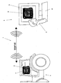
- the drawing shows a data connection system between an agricultural on-board computer and a diagnostic and service computer in a schematic representation.
- an agricultural on-board computer 2 for setting, control and / or regulation of the arranged on the tractor agricultural machinery, the tractor itself or its adjusting elements and devices arranged.
- the on-board computer 2 has a display-like display device designed as a display 3, on which by means of the display and display 4, for example, the program sequences or various parameters are displayed on.
- the on-board computer 2 has, for example, operating devices designed as buttons 5.
- Operation device input commands can be input to the on-board computer 2. By means of these input keys 5 can be navigated through the menu or the program of the on-board computer 2.
- the operator of the agricultural machine does not operate the on-board computer 2 properly or the on-board computer 2 displays error messages that the operator of the agricultural machine can not interpret correctly, he often accesses the cell phone or telephone for advice and instructions from a service employee S of the agricultural machine manufacturer or the manufacturer to get the on-board computer.
- the service employee S connects a diagnostic computer 6 via a remote data connection 7, for example an Internet connection with the on-board computer 2 of the user seeking help of the agricultural machine.
- the diagnostic or service computer 6 has an operating device 8 and a screen-like display 9.
- the diagnostic and service computer 6 or its software is designed such that on the display device 9 of the diagnostic computer 6, the image of the display 3 and control device 5 of the on-board computer 2, for example in the form of Figure 10 is shown.
- the display 4 is displayed on the display device 3 of the on-board computer 2 and the operating device 5 are displayed and updated in real time on the display device 9 of the computer 6.
- the service employee S recognizes which display 4 on the display 3 of the On-board computer is currently displayed and which controls, such as buttons 5 or other menu controls the operator presses the agricultural machine.
- the service employee S recognizes which representation 4 is currently displayed on the on-board computer 2 and which buttons 4 or other operating elements the operator of the agricultural machine actually actuates.
- the service agent S can thus detect whether the operator of the agricultural machine has correctly programmed the on-board computer 2, has called up the correct menu which has actuated the correct key 4 or key combination for the respective case.
- the service person S can follow the operator without the operator of the agricultural machine or the on-board computer having to explain which operating steps he performs.
- the service person S can accurately follow the sequence of operations, intervene in the operation sequences and / or simply and without many words show the operator the correct operation.
- the remote data transmission 7 can be used for remote commissioning and remote control of the onboard computer 2 or the agricultural machine.
- the remote data connection 7 can be used for remote control or remote monitoring of the onboard computer 2 or the agricultural machine. Because the entire displays and representations on the display 3 are also displayed on the screen 9 of the service computer 6. Around to ensure that the operator performs the other operations properly, the remote data link 7 for remote control and remote monitoring of the operator of the on-board computer 2 by the operator of the on-board computer 2 can be used. If error messages occur again, the service person S can exactly understand which operating steps have been carried out by the operator of the agricultural machine in order to investigate the cause and to be able to carry out a fault diagnosis. Thus, it is therefore possible to assist the operator of the agricultural machine via the remote data transmission device 7 from the workstation of the service employee S by the service employee S.
Abstract
Description
Die Erfindung betrifft ein Datenverbindungssystem gemäß des Oberbegriffes des Patentanspruches 1.The invention relates to a data connection system according to the preamble of
Durch die
Ein weiteres derartiges Datenverbindungssystem ist durch die
Immer komplexer werdende Maschinenstrukturen und flexible Menüstrukturen führen häufig zu Bedienungsfehlern der Bordcomputer durch den Bediener von Landmaschinen.Increasingly complex machine structures and flexible menu structures often lead to operating errors of the on-board computer by the operator of agricultural machinery.
Derzeit ist das übliche Vorgehen, dass die Bediener von Landmaschinen zum Handy greifen und den Service-Dienst der Landmaschinenhersteller anrufen.Currently, the common practice is for agricultural machine operators to pick up their mobile phones and call the service providers of agricultural machinery manufacturers.
Hierbei ist problematisch, dass der Service-Mitarbeiter des Landmaschinenherstellers nicht sieht, was auf dem Bordcomputer des Kunden passiert. Er ist auf die Beschreibung der Bildschirminhalte durch den Bediener der Landmaschine angewiesen. Weiterhin können Fehler durch das Betätigen falscher Tasten durch den Bediener von dem Service-Mitarbeiter nicht nachvollzogen werden, da der Bediener immer wieder den gleichen Fehler macht. Häufig kommt es vor, dass z. B. rechts, links, oben, unten vertauscht wird.Here is a problem that the service employee of the agricultural machinery manufacturer does not see what is happening on the customer's on-board computer. He depends on the description of the screen contents by the operator of the agricultural machine. Furthermore, errors can not be traced by the operator pressing wrong keys by the service person because the operator always makes the same mistake. It often happens that z. B. is reversed right, left, up, down.
Entsprechend der Maßnahmen gemäß der Merkmale der Ansprüche 4 und 5 kann der Service-Mitarbeiter den Bordcomputer oder die Landmaschine fernbedienen, eine Fernkontrolle oder eine Fernüberwachung durchführen.According to the measures according to the features of claims 4 and 5, the service staff can remotely control the on-board computer or the agricultural machine, perform a remote control or a remote monitoring.
Um die tatsächlichen Vorgänge auf dem Bildschirm des Service-Mitarbeiters S darstellen zu können, ist vorgesehen, dass die Abbildung auf der Anzeigevorrichtung des Bordcomputers in Echtzeit auf der der Anzeigevorrichtung des Computers anzeigund/oder aktualisierbar ist.In order to be able to display the actual operations on the screen of the service employee S, it is provided that the image on the display device of the on-board computer can be displayed and / or updated in real time on that of the display device of the computer.
Weitere Einzelheiten der Erfindung sind den übrigen Unteransprüchen, der Beispielsbeschreibung und der Zeichnung zu entnehmen. Die Zeichnung zeigt
ein Datenverbindungssystem zwischen einem landwirtschaftlichen Bordcomputer und einem Diagnose- und Service-Computer in Prinzipdarstellung.Further details of the invention can be taken from the remaining subclaims, the example description and the drawing. The drawing shows
a data connection system between an agricultural on-board computer and a diagnostic and service computer in a schematic representation.
Auf dem eine nicht dargestellte Landmaschine ziehenden oder tragenden Schlepper 1 ist ein landwirtschaftlicher Bordcomputer 2 zur Einstellung, Steuerung und/oder Regelung von der an dem Ackerschlepper angeordneten Landmaschine, dem Schlepper selbst oder deren Einstellelementen und Vorrichtungen, angeordnet. Der Bordcomputer 2 weist eine als Display 3 ausgebildete bildschirmähnliche Anzeigevorrichtung, auf welcher mittels der Anzeige und Darstellung 4, beispielsweise die Programmabläufe oder verschiedene Parameter angezeigt werden, auf. Weiterhin weist der Bordcomputer 2 beispielsweise als Tasten 5 ausgebildete Bedienungsvorrichtungen auf. Über die als Tasten ausgebildete Bedienungsvorrichtung können Eingabebefehle an den Bordcomputer 2 eingegeben werden. Mittels dieser Eingabetasten 5 kann durch das Menü oder das Programm des Bordcomputers 2 navigiert werden.On the agricultural machine, not shown pulling or carrying
Wenn der Bediener der Landmaschine den Bordcomputer 2 nicht richtig bedient oder der Bordcomputer 2 Fehlermeldungen anzeigt, die der Bediener der Landmaschine nicht richtig interpretieren kann, greift er häufig zum Handy oder Telefon um Ratschläge und Anweisungen von einem Service-Mitarbeiter S des Landmaschinenherstellers oder des Herstellers des Bordcomputers zu erhalten.If the operator of the agricultural machine does not operate the on-board computer 2 properly or the on-board computer 2 displays error messages that the operator of the agricultural machine can not interpret correctly, he often accesses the cell phone or telephone for advice and instructions from a service employee S of the agricultural machine manufacturer or the manufacturer to get the on-board computer.
Die Schwierigkeit besteht nun darin, dass der Service-Mitarbeiter S sich auf die mündlichen Beschreibungen des Bedieners der Landmaschine verlassen muss und es hier häufig zu Missverständnissen kommt.The difficulty now is that the service employee S must rely on the verbal descriptions of the operator of the agricultural machine and it often comes to misunderstandings here.
Um diesem abzuhelfen, verbindet der Service-Mitarbeiter S einen Diagnosecomputer 6 über eine Datenfernverbindung 7, beispielsweise einer Internetverbindung mit dem Bordcomputer 2 des Hilfe suchenden Bedieners der Landmaschine. Der Diagnose- oder Service-Computer 6 weist eine Bedienungsvorrichtung 8 und eine bildschirmähnliche Anzeige 9 auf. Hierbei ist der Diagnose- und Service-Computer 6 bzw. dessen Software derart ausgelegt, dass auf der Anzeigevorrichtung 9 des Diagnose-Computers 6 die Abbildung der Anzeigen 3 und Bedienungsvorrichtung 5 des Bordcomputers 2 beispielsweise in form der Abbildung 10 abbildbar ist. Die Darstellung 4 ist auf der Anzeigevorrichtung 3 des Bordcomputers 2 und die Bedienungsvorrichtung 5 werden in Echtzeit auf der Anzeigevorrichtung 9 des Computers 6 angezeigt und aktualisiert. Hierüber erkennt der Service-Mitarbeiter S, welche Anzeige 4 auf dem Display 3 des Bordcomputers aktuell dargestellt wird und welche Bedienelemente, beispielsweise Tasten 5 oder andere Menü-Bedienungselemente der Bediener der Landmaschine betätigt. Somit erkennt der Service-Mitarbeiter S welche Darstellung 4 auf dem Bordcomputer 2 aktuell angezeigt wird und welche Tasten 4 oder andere Bedienelemente der Bediener der Landmaschine tatsächlich betätigt. Der Service-Mitarbeiter S kann somit erkennen, ob der Bediener der Landmaschine den Bordcomputer 2 richtig programmiert hat, eingeschaltet hat, das richtige Menü aufgerufen hat, die richtige Taste 4 oder Tastenkombination für den jeweiligen Fall betätigt hat. Der Service-Mitarbeiter S kann dem Bediener folgen, ohne dass der Bediener der Landmaschine bzw. des Bordcomputers erläutern muss, welche Bedienungsschritte er durchführt.To remedy this, the service employee S connects a
Somit kann der Service-Mitarbeiter S die Bedienungsabfolgen genau nachvollziehen, in die Bedienungsabfolgen eingreifen und/oder einfach und ohne viele Worte dem Bediener die richtige Bedienung zeigen.Thus, the service person S can accurately follow the sequence of operations, intervene in the operation sequences and / or simply and without many words show the operator the correct operation.
Des Weiteren sind mittels des Diagnose- und/oder Service-Computers 6 Eingabebefehle an den Bordcomputer 2 zu übermitteln, so dass die Landmaschine durch den Service-Mitarbeiter S einzustellen, zu steuern und zu regeln ist.Furthermore, by means of the diagnostic and / or
Auch kann die Datenfernübertragung 7 zur Ferninbetriebnahme und Fernbedienung des Bordcomputers 2 oder der Landmaschine genutzt werden.Also, the remote data transmission 7 can be used for remote commissioning and remote control of the onboard computer 2 or the agricultural machine.
Weiterhin kann die Datenfernverbindung 7 zur Fernkontrolle oder Fernüberwachung des Bordcomputers 2 oder der Landmaschine genutzt werden. Denn die gesamten Anzeigen und Darstellungen auf dem Display 3 werden auch auf dem Bildschirm 9 des Service-Computers 6 angezeigt. Um sicherzugehen, dass der Bediener die weiteren Bedienungsschritte richtig durchführt, kann die Datenfernverbindung 7 zur Fernkontrolle und Fernüberwachung des Bedieners des Bordcomputers 2 durch den Bediener des Bordcomputers 2 genutzt werden um. Falls wieder Fehlermeldungen auftreten, kann der Service-Mitarbeiter S genau nachvollziehen, welche Bedienungsschritte durch den Bediener der Landmaschine durchgeführt worden sind, um so die Ursache zu erforschen und eine Fehlerdiagnose durchführen zu können. Somit kann also über die Datenfernübertragungseinrichtung 7 vom Arbeitsplatz des Service-Mitarbeiters S durch den Service-Mitarbeiter S dem Bediener der Landmaschine geholfen werden.Furthermore, the remote data connection 7 can be used for remote control or remote monitoring of the onboard computer 2 or the agricultural machine. Because the entire displays and representations on the display 3 are also displayed on the screen 9 of the
Somit sieht der Service-Mitarbeiter S was auf dem Bordcomputer 2 des Kunden passiert und ist nicht auf die mündliche Beschreibung der Bildschirminhalte 4 und der mündlichen Schilderung der Bedienungsschritte angewiesen.Thus, the service worker S sees what is happening on the customer's on-board computer 2 and is not dependent on the verbal description of the screen contents 4 and the verbal description of the operating steps.
Claims (7)
- Data connection system between a diagnostic and/or service computer and an agricultural on-board computer for adjusting/ controlling and/or regulating agricultural machines and/or their adjusting elements and devices using a screen-like display device, such as, for example, a display unit , wherein the on-board computer is connectable to a diagnostic and/or service computer by means of a remote data transmission device, wherein the diagnostic and/or service computer (6) has an operating device (8) and a screen-like display unit (9) and wherein images (10) can be imaged on the display device (9) of the diagnostic computer (6), characterised in that the images (10) are the display and operating device (4) of the on-board computer (2), in that between the on-board computer (2) and the diagnostic computer (6) data transmission can be set up such that a copy of the screen content and/or of the operating elements of the on-board computer of the machine is represented on the screen of the diagnostic and/or service computer.
- Data connection system according to claim 1, characterised in that input instructions can be transmitted to the on-board computer (2) by means of the diagnostic and/or service computer and the agricultural machine is adjustable, controllable and/or regulatable in this manner.
- Data connection system according to claim 1, characterised in that the remote data connection (7) can be used for the remote start-up of the on-board computer (2) and/or of the agricultural machine.
- Data connection system according to claim 1, characterised in that the remote data connection (7) can be used for the remote operation of the on-board computer (2) and/or of the agricultural machine.
- Data connection system according to claim 1, characterised in that the remote data connection (7) can be used for the remote control and/or remote monitoring of the on-board computer (2) and/or of the agricultural machine.
- Data connection system according to claim 1, characterised in that the remote data connection (7) can be used for the remote control and/or remote monitoring of the operation of the on-board computer (2) by the operator of the on-board computer (2).
- Data connection system according to one or more of the preceding claims, characterised in that the image (4, 10) on the display device (3) of the on-board computer (2) can be displayed and/or up-dated in real time on the display device (9) of the computer (6).
Priority Applications (1)
| Application Number | Priority Date | Filing Date | Title |
|---|---|---|---|
| PL07008494T PL1852007T3 (en) | 2006-05-04 | 2007-04-26 | Data connection system |
Applications Claiming Priority (1)
| Application Number | Priority Date | Filing Date | Title |
|---|---|---|---|
| DE102006020704A DE102006020704A1 (en) | 2006-05-04 | 2006-05-04 | Data link system |
Publications (3)
| Publication Number | Publication Date |
|---|---|
| EP1852007A1 EP1852007A1 (en) | 2007-11-07 |
| EP1852007B1 true EP1852007B1 (en) | 2009-02-25 |
| EP1852007B9 EP1852007B9 (en) | 2009-08-12 |
Family
ID=38266671
Family Applications (1)
| Application Number | Title | Priority Date | Filing Date |
|---|---|---|---|
| EP07008494A Active EP1852007B9 (en) | 2006-05-04 | 2007-04-26 | Data connection system |
Country Status (5)
| Country | Link |
|---|---|
| EP (1) | EP1852007B9 (en) |
| AT (1) | ATE423451T1 (en) |
| DE (2) | DE102006020704A1 (en) |
| DK (1) | DK1852007T3 (en) |
| PL (1) | PL1852007T3 (en) |
Families Citing this family (1)
| Publication number | Priority date | Publication date | Assignee | Title |
|---|---|---|---|---|
| EP3245856B1 (en) * | 2014-06-18 | 2019-11-20 | Deere & Company | Assembly for controlling a device interface of an agricultural work vehicle |
Family Cites Families (3)
| Publication number | Priority date | Publication date | Assignee | Title |
|---|---|---|---|---|
| US20020116107A1 (en) * | 2001-02-07 | 2002-08-22 | Deere & Company | Method of monitoring equipment of an agricultural machine |
| US20020107624A1 (en) * | 2001-02-07 | 2002-08-08 | Deere & Company, A Delaware Corporation | Monitoring equipment for an agricultural machine |
| DE10217398B4 (en) | 2001-06-12 | 2007-06-28 | Gebr. Pöttinger GmbH | Agricultural machine and method for controlling an agricultural machine |
-
2006
- 2006-05-04 DE DE102006020704A patent/DE102006020704A1/en not_active Withdrawn
-
2007
- 2007-04-26 AT AT07008494T patent/ATE423451T1/en active
- 2007-04-26 DE DE502007000454T patent/DE502007000454D1/en active Active
- 2007-04-26 EP EP07008494A patent/EP1852007B9/en active Active
- 2007-04-26 DK DK07008494T patent/DK1852007T3/en active
- 2007-04-26 PL PL07008494T patent/PL1852007T3/en unknown
Also Published As
| Publication number | Publication date |
|---|---|
| DK1852007T3 (en) | 2009-05-11 |
| ATE423451T1 (en) | 2009-03-15 |
| EP1852007B9 (en) | 2009-08-12 |
| DE102006020704A1 (en) | 2007-11-08 |
| EP1852007A1 (en) | 2007-11-07 |
| PL1852007T3 (en) | 2009-06-30 |
| DE502007000454D1 (en) | 2009-04-09 |
Similar Documents
| Publication | Publication Date | Title |
|---|---|---|
| DE102018110742A1 (en) | Method and device for servicing and / or repairing a construction machine | |
| EP3383598B1 (en) | Manipulator system and method for identifying operating devices | |
| EP1941331B1 (en) | Apparatus for operating a process installation | |
| EP1156148B1 (en) | Device for communicating data between a sewing machine and a central computer | |
| DE102012010721A1 (en) | Engine control apparatus for controlling movement of machine, has coupling device that is provided for virtual coupling of movement of mechanical component with movement of portable operation unit, based on movement signal | |
| EP2711795A1 (en) | Method for remote controlling a device, in particular a field device, and device assembly | |
| EP3001310A1 (en) | Method and apparatus for updating firmware for components of an industrial automation system | |
| EP1852007B1 (en) | Data connection system | |
| EP2851757A2 (en) | Customer-specific configuration and parametrisation of fill level measuring devices in an ordering procedure | |
| EP2927186B9 (en) | Method and system for operating an industrial truck | |
| EP2881018B1 (en) | Device for automated preparation of a hot drink | |
| DE102009038479A1 (en) | Method for transmitting data to controllers of vehicle, involves connecting controllers electronically with electrical plug-in-connector of vehicle for bidirectional communication | |
| EP1785794A2 (en) | Display of preconditions during the input of operational commands | |
| EP1798620A1 (en) | System and method for remote analysis,remote maintenance and/or remote error recovery of a technical equipment. | |
| DE60132719T2 (en) | COMPUTER SYSTEM FOR FERDIAGNOSTICS AND CONFIGURATION OF A FIELD DEVICE | |
| DE102008002053A1 (en) | Control system for a printing machine i.e. sheet-fed printing press, has manually operatable indicating device allowing person working at printing machine to transmit data to and/or printing machine controller and/or machine control panel | |
| DE102005007477B4 (en) | Programmable control for machine and / or plant automation with standard control and safety functions and communication with a safety I / O and method for operating the programmable controller | |
| DE102013107993A1 (en) | Filling management for pesticides | |
| US9667692B2 (en) | System and method for remote analysis, remote training or remote maintenance on a mobile machine | |
| EP1227647A1 (en) | Diagnosis and maintenance of machines via transmission of multi media messages in realtime | |
| EP1331535A1 (en) | Field bus device | |
| EP1478990B1 (en) | Method for transferring field device data to an external data bank | |
| DE10164667C1 (en) | Pressurised air conditioning device has condition data processing device incorporated in external unit having data input and/or output devices | |
| EP3624029B1 (en) | Digitally managed unloading process of of a transport vehicle | |
| DE112021007454T5 (en) | Remote maintenance system |
Legal Events
| Date | Code | Title | Description |
|---|---|---|---|
| PUAI | Public reference made under article 153(3) epc to a published international application that has entered the european phase |
Free format text: ORIGINAL CODE: 0009012 |
|
| AK | Designated contracting states |
Kind code of ref document: A1 Designated state(s): AT BE BG CH CY CZ DE DK EE ES FI FR GB GR HU IE IS IT LI LT LU LV MC MT NL PL PT RO SE SI SK TR |
|
| AX | Request for extension of the european patent |
Extension state: AL BA HR MK YU |
|
| 17P | Request for examination filed |
Effective date: 20080507 |
|
| 17Q | First examination report despatched |
Effective date: 20080606 |
|
| AKX | Designation fees paid |
Designated state(s): AT BE BG CH CY CZ DE DK EE ES FI FR GB GR HU IE IS IT LI LT LU LV MC MT NL PL PT RO SE SI SK TR |
|
| GRAP | Despatch of communication of intention to grant a patent |
Free format text: ORIGINAL CODE: EPIDOSNIGR1 |
|
| GRAS | Grant fee paid |
Free format text: ORIGINAL CODE: EPIDOSNIGR3 |
|
| GRAA | (expected) grant |
Free format text: ORIGINAL CODE: 0009210 |
|
| AK | Designated contracting states |
Kind code of ref document: B1 Designated state(s): AT BE BG CH CY CZ DE DK EE ES FI FR GB GR HU IE IS IT LI LT LU LV MC MT NL PL PT RO SE SI SK TR |
|
| REG | Reference to a national code |
Ref country code: GB Ref legal event code: FG4D Free format text: NOT ENGLISH |
|
| REG | Reference to a national code |
Ref country code: CH Ref legal event code: EP |
|
| REG | Reference to a national code |
Ref country code: IE Ref legal event code: FG4D Free format text: LANGUAGE OF EP DOCUMENT: GERMAN |
|
| REF | Corresponds to: |
Ref document number: 502007000454 Country of ref document: DE Date of ref document: 20090409 Kind code of ref document: P |
|
| REG | Reference to a national code |
Ref country code: DK Ref legal event code: T3 |
|
| REG | Reference to a national code |
Ref country code: SE Ref legal event code: TRGR |
|
| REG | Reference to a national code |
Ref country code: PL Ref legal event code: T3 |
|
| PG25 | Lapsed in a contracting state [announced via postgrant information from national office to epo] |
Ref country code: NL Free format text: LAPSE BECAUSE OF FAILURE TO SUBMIT A TRANSLATION OF THE DESCRIPTION OR TO PAY THE FEE WITHIN THE PRESCRIBED TIME-LIMIT Effective date: 20090225 Ref country code: SI Free format text: LAPSE BECAUSE OF FAILURE TO SUBMIT A TRANSLATION OF THE DESCRIPTION OR TO PAY THE FEE WITHIN THE PRESCRIBED TIME-LIMIT Effective date: 20090225 Ref country code: LT Free format text: LAPSE BECAUSE OF FAILURE TO SUBMIT A TRANSLATION OF THE DESCRIPTION OR TO PAY THE FEE WITHIN THE PRESCRIBED TIME-LIMIT Effective date: 20090225 Ref country code: FI Free format text: LAPSE BECAUSE OF FAILURE TO SUBMIT A TRANSLATION OF THE DESCRIPTION OR TO PAY THE FEE WITHIN THE PRESCRIBED TIME-LIMIT Effective date: 20090225 |
|
| NLV1 | Nl: lapsed or annulled due to failure to fulfill the requirements of art. 29p and 29m of the patents act | ||
| PG25 | Lapsed in a contracting state [announced via postgrant information from national office to epo] |
Ref country code: LV Free format text: LAPSE BECAUSE OF FAILURE TO SUBMIT A TRANSLATION OF THE DESCRIPTION OR TO PAY THE FEE WITHIN THE PRESCRIBED TIME-LIMIT Effective date: 20090225 Ref country code: IS Free format text: LAPSE BECAUSE OF FAILURE TO SUBMIT A TRANSLATION OF THE DESCRIPTION OR TO PAY THE FEE WITHIN THE PRESCRIBED TIME-LIMIT Effective date: 20090625 |
|
| REG | Reference to a national code |
Ref country code: IE Ref legal event code: FD4D |
|
| PG25 | Lapsed in a contracting state [announced via postgrant information from national office to epo] |
Ref country code: EE Free format text: LAPSE BECAUSE OF FAILURE TO SUBMIT A TRANSLATION OF THE DESCRIPTION OR TO PAY THE FEE WITHIN THE PRESCRIBED TIME-LIMIT Effective date: 20090225 Ref country code: PT Free format text: LAPSE BECAUSE OF FAILURE TO SUBMIT A TRANSLATION OF THE DESCRIPTION OR TO PAY THE FEE WITHIN THE PRESCRIBED TIME-LIMIT Effective date: 20090812 Ref country code: IE Free format text: LAPSE BECAUSE OF FAILURE TO SUBMIT A TRANSLATION OF THE DESCRIPTION OR TO PAY THE FEE WITHIN THE PRESCRIBED TIME-LIMIT Effective date: 20090225 Ref country code: ES Free format text: LAPSE BECAUSE OF FAILURE TO SUBMIT A TRANSLATION OF THE DESCRIPTION OR TO PAY THE FEE WITHIN THE PRESCRIBED TIME-LIMIT Effective date: 20090605 Ref country code: CZ Free format text: LAPSE BECAUSE OF FAILURE TO SUBMIT A TRANSLATION OF THE DESCRIPTION OR TO PAY THE FEE WITHIN THE PRESCRIBED TIME-LIMIT Effective date: 20090225 |
|
| BERE | Be: lapsed |
Owner name: AMAZONEN-WERKE H. DREYER G.M.B.H. & CO. KG Effective date: 20090430 |
|
| PG25 | Lapsed in a contracting state [announced via postgrant information from national office to epo] |
Ref country code: SK Free format text: LAPSE BECAUSE OF FAILURE TO SUBMIT A TRANSLATION OF THE DESCRIPTION OR TO PAY THE FEE WITHIN THE PRESCRIBED TIME-LIMIT Effective date: 20090225 Ref country code: RO Free format text: LAPSE BECAUSE OF FAILURE TO SUBMIT A TRANSLATION OF THE DESCRIPTION OR TO PAY THE FEE WITHIN THE PRESCRIBED TIME-LIMIT Effective date: 20090225 |
|
| PLBE | No opposition filed within time limit |
Free format text: ORIGINAL CODE: 0009261 |
|
| STAA | Information on the status of an ep patent application or granted ep patent |
Free format text: STATUS: NO OPPOSITION FILED WITHIN TIME LIMIT |
|
| PG25 | Lapsed in a contracting state [announced via postgrant information from national office to epo] |
Ref country code: BG Free format text: LAPSE BECAUSE OF FAILURE TO SUBMIT A TRANSLATION OF THE DESCRIPTION OR TO PAY THE FEE WITHIN THE PRESCRIBED TIME-LIMIT Effective date: 20090525 |
|
| 26N | No opposition filed |
Effective date: 20091126 |
|
| PG25 | Lapsed in a contracting state [announced via postgrant information from national office to epo] |
Ref country code: MC Free format text: LAPSE BECAUSE OF NON-PAYMENT OF DUE FEES Effective date: 20090430 |
|
| PG25 | Lapsed in a contracting state [announced via postgrant information from national office to epo] |
Ref country code: BE Free format text: LAPSE BECAUSE OF NON-PAYMENT OF DUE FEES Effective date: 20090430 |
|
| PG25 | Lapsed in a contracting state [announced via postgrant information from national office to epo] |
Ref country code: GR Free format text: LAPSE BECAUSE OF FAILURE TO SUBMIT A TRANSLATION OF THE DESCRIPTION OR TO PAY THE FEE WITHIN THE PRESCRIBED TIME-LIMIT Effective date: 20090526 |
|
| PG25 | Lapsed in a contracting state [announced via postgrant information from national office to epo] |
Ref country code: IT Free format text: LAPSE BECAUSE OF FAILURE TO SUBMIT A TRANSLATION OF THE DESCRIPTION OR TO PAY THE FEE WITHIN THE PRESCRIBED TIME-LIMIT Effective date: 20090225 |
|
| PG25 | Lapsed in a contracting state [announced via postgrant information from national office to epo] |
Ref country code: LU Free format text: LAPSE BECAUSE OF NON-PAYMENT OF DUE FEES Effective date: 20090426 |
|
| PG25 | Lapsed in a contracting state [announced via postgrant information from national office to epo] |
Ref country code: HU Free format text: LAPSE BECAUSE OF FAILURE TO SUBMIT A TRANSLATION OF THE DESCRIPTION OR TO PAY THE FEE WITHIN THE PRESCRIBED TIME-LIMIT Effective date: 20090826 |
|
| PG25 | Lapsed in a contracting state [announced via postgrant information from national office to epo] |
Ref country code: TR Free format text: LAPSE BECAUSE OF FAILURE TO SUBMIT A TRANSLATION OF THE DESCRIPTION OR TO PAY THE FEE WITHIN THE PRESCRIBED TIME-LIMIT Effective date: 20090225 |
|
| PG25 | Lapsed in a contracting state [announced via postgrant information from national office to epo] |
Ref country code: CY Free format text: LAPSE BECAUSE OF FAILURE TO SUBMIT A TRANSLATION OF THE DESCRIPTION OR TO PAY THE FEE WITHIN THE PRESCRIBED TIME-LIMIT Effective date: 20090225 |
|
| REG | Reference to a national code |
Ref country code: CH Ref legal event code: PL |
|
| PG25 | Lapsed in a contracting state [announced via postgrant information from national office to epo] |
Ref country code: CH Free format text: LAPSE BECAUSE OF NON-PAYMENT OF DUE FEES Effective date: 20110430 Ref country code: LI Free format text: LAPSE BECAUSE OF NON-PAYMENT OF DUE FEES Effective date: 20110430 |
|
| PGFP | Annual fee paid to national office [announced via postgrant information from national office to epo] |
Ref country code: GB Payment date: 20120425 Year of fee payment: 6 |
|
| GBPC | Gb: european patent ceased through non-payment of renewal fee |
Effective date: 20130426 |
|
| PG25 | Lapsed in a contracting state [announced via postgrant information from national office to epo] |
Ref country code: GB Free format text: LAPSE BECAUSE OF NON-PAYMENT OF DUE FEES Effective date: 20130426 |
|
| REG | Reference to a national code |
Ref country code: FR Ref legal event code: PLFP Year of fee payment: 10 |
|
| REG | Reference to a national code |
Ref country code: FR Ref legal event code: PLFP Year of fee payment: 11 |
|
| REG | Reference to a national code |
Ref country code: FR Ref legal event code: PLFP Year of fee payment: 12 |
|
| REG | Reference to a national code |
Ref country code: DE Ref legal event code: R081 Ref document number: 502007000454 Country of ref document: DE Owner name: AMAZONEN-WERKE H. DREYER SE & CO. KG, DE Free format text: FORMER OWNER: AMAZONEN-WERKE H. DREYER GMBH & CO. KG, 49205 HASBERGEN, DE |
|
| PGFP | Annual fee paid to national office [announced via postgrant information from national office to epo] |
Ref country code: FR Payment date: 20230309 Year of fee payment: 17 |
|
| PGFP | Annual fee paid to national office [announced via postgrant information from national office to epo] |
Ref country code: SE Payment date: 20230310 Year of fee payment: 17 Ref country code: PL Payment date: 20230314 Year of fee payment: 17 |
|
| P01 | Opt-out of the competence of the unified patent court (upc) registered |
Effective date: 20230523 |
|
| PGFP | Annual fee paid to national office [announced via postgrant information from national office to epo] |
Ref country code: DK Payment date: 20230414 Year of fee payment: 17 Ref country code: DE Payment date: 20230307 Year of fee payment: 17 |
|
| PGFP | Annual fee paid to national office [announced via postgrant information from national office to epo] |
Ref country code: AT Payment date: 20230327 Year of fee payment: 17 |