EP1851677B1 - Combination barcode imaging/decoding and real-time video capture system - Google Patents
Combination barcode imaging/decoding and real-time video capture system Download PDFInfo
- Publication number
- EP1851677B1 EP1851677B1 EP05791691A EP05791691A EP1851677B1 EP 1851677 B1 EP1851677 B1 EP 1851677B1 EP 05791691 A EP05791691 A EP 05791691A EP 05791691 A EP05791691 A EP 05791691A EP 1851677 B1 EP1851677 B1 EP 1851677B1
- Authority
- EP
- European Patent Office
- Prior art keywords
- barcode
- decoding
- mode
- imaging
- barcode scanner
- Prior art date
- Legal status (The legal status is an assumption and is not a legal conclusion. Google has not performed a legal analysis and makes no representation as to the accuracy of the status listed.)
- Expired - Lifetime
Links
Images

Classifications
-
- G—PHYSICS
- G06—COMPUTING OR CALCULATING; COUNTING
- G06K—GRAPHICAL DATA READING; PRESENTATION OF DATA; RECORD CARRIERS; HANDLING RECORD CARRIERS
- G06K7/00—Methods or arrangements for sensing record carriers, e.g. for reading patterns
- G06K7/10—Methods or arrangements for sensing record carriers, e.g. for reading patterns by electromagnetic radiation, e.g. optical sensing; by corpuscular radiation
- G06K7/10544—Methods or arrangements for sensing record carriers, e.g. for reading patterns by electromagnetic radiation, e.g. optical sensing; by corpuscular radiation by scanning of the records by radiation in the optical part of the electromagnetic spectrum
- G06K7/10821—Methods or arrangements for sensing record carriers, e.g. for reading patterns by electromagnetic radiation, e.g. optical sensing; by corpuscular radiation by scanning of the records by radiation in the optical part of the electromagnetic spectrum further details of bar or optical code scanning devices
- G06K7/10881—Methods or arrangements for sensing record carriers, e.g. for reading patterns by electromagnetic radiation, e.g. optical sensing; by corpuscular radiation by scanning of the records by radiation in the optical part of the electromagnetic spectrum further details of bar or optical code scanning devices constructional details of hand-held scanners
-
- G—PHYSICS
- G06—COMPUTING OR CALCULATING; COUNTING
- G06K—GRAPHICAL DATA READING; PRESENTATION OF DATA; RECORD CARRIERS; HANDLING RECORD CARRIERS
- G06K7/00—Methods or arrangements for sensing record carriers, e.g. for reading patterns
- G06K7/10—Methods or arrangements for sensing record carriers, e.g. for reading patterns by electromagnetic radiation, e.g. optical sensing; by corpuscular radiation
Definitions
- the present disclosure relates generally to barcode imaging/decoding systems and real-time video capture systems for video surveillance purposes.
- the present disclosure relates to a combination barcode imaging/decoding and real-time video capture system.
- the present disclosure relates to a point-of-sale barcode imaging/decoding and real-time video capture system.
- Point-of-sale (POS) systems such as self-checkout POS stations which enable consumers to scan product barcodes and purchase products without the aid of a sales clerk, are widely implemented at point-of-sale locations in many retail outlets.
- the POS locations are generally monitored by video surveillance systems having a plurality of video cameras to deter theft of products by consumers using self-checkout POS stations or to aid in apprehending thieves who commit robbery by accosting a retail clerk at a POS station.
- the retail outlets employ a single video camera for capturing real-time video of a field of view which can include within it several POS stations.
- the real-time video is typically transmitted to a video surveillance monitoring system for enabling security personnel to conduct video surveillance.
- the single video camera In order for each POS station to be in the field of view or line-of-sight of the video camera, the single video camera is positioned at a substantial distance from each POS station. It has been observed that an individual at a self-checkout POS station who intends to steal items is aware of the video camera in the line-of-sight of the POS station. The individual typically positions himself in a manner which blocks the line-of-sight and security personnel monitoring the incoming real-time video from the video camera are unable to detect whether the individual is stealing items.
- US-A-6,726,094 discloses a customer self-service terminal for use in conducting retail transactions.
- the terminal includes a camera having multimode image capability.
- the camera is used to scan product barcodes.
- the camera is set to capture an image of a barcode for extraction of data contained in the barcode.
- the camera is used to record steps in the tendering of payment.
- the customer presents a financial identification card such as a credit or debit card and swipes it through a magnetic stripe reader.
- the customer places the card in the field of view of the camera which is set to a video graphic mode to capture an image of the card for storage.
- the customer is then presented with a transaction document for signing.
- the camera is set to a live video mode to record the act of signing. After the transaction document has been signed, the camera captures an image of the signature. The captured images are associated with the transaction record and stored along with the transaction record, and the transaction is completed.
- the camera may also be set to provide a live video feed, which may be used sent to a remote security station for monitoring by a store employee.
- US-A-5,682,030 discloses a method and apparatus for decoding bar code data from a video signal, wherein a bar code within a composite video signal may be detected and decoded.
- the composite video signal is converted into a form suitable for providing to a bar code decoder, in order that any bar code within the video signal may be decoded by the decoder.
- the output of the bar code decoder may thereafter be provided to, for example, a computer for the further processing.
- the composite video signal which is decoded may be generated by a video camera, a video tape recorder, a television signal, or any other source which generates such a video signal. Bar codes detected by video cameras in different environments may be decoded and processed by a computer.
- EP-A-0 873 013 discloses a process which allows an image capturing apparatus to be integrated with a personal computer to continuously display a video image of the imaging apparatus. Upon proper input by a user, or automatically after a timed interval, a snapshot of the video image is captured. An autodiscrimination process of the captured video image automatically decodes any bar-coded information present in the captured image and outputs the information.
- the present disclosure provides a combination barcode imaging/decoding and real-time video capture system, as set forth in claim 1.
- the system is configured for being implemented at a POS location for performing the functions of barcode imaging and decoding, and real-time video capture for video surveillance purposes.
- the system includes an imager or imaging sensor as known in the art and a switching mechanism for switching and operating the imager between a barcode imaging and decoding mode for imaging and decoding barcodes positioned in proximity to the imager, and a real-time video capture mode for capturing real-time video for video surveillance purposes.
- the present disclosure further provides a POS station, such as a self-checkout POS station, having the features of the combination system.
- the present disclosure further provides a method of operating a combination barcode imaging/decoding and real-time video capture system as set forth in claim 9.
- the combination barcode imaging/decoding and real-time video capture system is selectively operated or switched between the two modes by detecting whether a barcode scanner housing the imager is positioned within a cradle. If the barcode scanner is positioned within the cradle, a signal is transmitted to a processing unit within the barcode scanner to operate the scanner in the real-time video capture mode. If the barcode scanner is not positioned within the cradle, the signal is not transmitted to the processing unit and the scanner is operated in a barcode imaging and decoding mode.
- the combination barcode imaging/decoding and real-time video capture system is selectively operated or switched between two modes of operation by determining if a barcode is positioned in proximity to the imager using conventional image processing techniques.
- a proximity sensor as known in the art is used for determining if an object is positioned within a predetermined distance range from the barcode scanner. If it is determined that an object is positioned within the predetermined distance range from the barcode scanner, the processing unit freezes a real-time image of the real-time video images relayed by the imager to the processing unit.
- the processing unit determines using conventional image processing techniques whether the image includes a barcode. If it is determined that the image includes a barcode, the processing unit switches the mode of operation from the real-time video capture mode to the barcode imaging and decoding mode, in order to re-image and decode the barcode. It is contemplated that the image relayed to the processing unit can be used decoding the barcode without re-imaging the barcode.
- the imaged barcode data is relayed to the processing unit of the barcode scanner or some other processing unit of the combination barcode imaging/decoding and real-time video capture system for decoding and thereby, determining the type of item, the price and/or other information for the scanned item as known in the art. A total cost for all the scanned items is then tallied by the system and displayed on a monitor.
- the present disclosure provides a combination or integrated barcode imaging/decoding and real-time video capture system.
- the system is configured for being implemented at a POS location for performing the functions of barcode imaging and decoding, and real-time video capture for video surveillance purposes.
- the system includes an imager or imaging sensor as known in the art and a switching mechanism for switching and operating the imager between a barcode imaging and decoding mode for imaging and decoding barcodes positioned in proximity to the imager, and a real-time video capture mode for capturing real-time video for video surveillance purposes.
- the present disclosure further provides a POS station, such as a self-checkout POS station, having the features of the combination system.
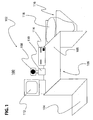
- FIG. 1 An exemplary embodiment of the combination system having a POS station is shown by FIG. 1 and designated generally by reference numeral 100.
- the POS station is of the self-checkout type which may include a weighing station and electronic article surveillance (EAS) system as known in the art. It is contemplated that other types of POS stations can be used with the system 100 of the present disclosure besides self-checkout POS stations.
- the POS station is designated by reference numeral 102.
- the POS station 102 includes a holding area 104 for placing items prior to scanning their respective barcodes.
- a checkout area 106 is provided adjacent to the holding area 104 having a working surface 105.
- the working surface 105 includes a barcode scanner 108 having an imager or imaging sensor 200, such as a charge-coupled device (CCD), and a lens assembly 202 housed within a housing 204.
- the imager 200 is preferably an imaging engine configured and dimensioned to fit within a predetermined form factor of the barcode scanner.
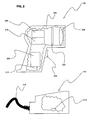
- the barcode scanner 108 further includes a triggering mechanism 206 (see FIGs. 2 and 2A ) for actuating a barcode imaging and decoding operation as known in the art and a processing unit 208 having at least one processor for executing a set of programmable instructions for operating the barcode scanner 108 and performing the functions described herein for the barcode scanner 108.
- the barcode scanner 108 further includes communication circuitry 209 and a battery pack 210 for enabling wireless operation of the barcode scanner 108.
- the processing unit 208 of the barcode scanner 108 in accordance with the present disclosure is capable of operating the barcode scanner 108 between a barcode imaging and decoding mode and a real-time video capture mode.
- the real-time video capture mode is similar in operation as that of a video camera, where moving video images are captured.
- a cradle 110 configured and dimensioned for positioning the barcode scanner 108 therein.
- the cradle 110 includes a switching mechanism for transmitting a signal to the processing unit 208 for effecting switching between the two modes of operation according to whether the barcode scanner 108 is positioned within the cradle 110.
- the switching mechanism includes a data interface connector 212 having data interface pins for connecting to a driver 214 on the barcode scanner 108.
- a signal is relayed from the data interface connector 212 to the driver 214, and subsequently from the driver 214 to the processing unit 208.
- the signal instructs the processing unit 208 to switch the mode of operation of the barcode scanner 108 from the barcode imaging and decoding mode to the real-time video capture mode.
- One or more additional signals can be related to the processing unit 208 from the data interface connector 212.
- the signals preferably provide software updates, including symbology decoding algorithms for one- and two-dimensional symbologies for programming or reprogramming a decoding unit of the processing unit 208.
- the real-time video captured during the operation of the barcode scanner 108 in the real-time video capture mode is transmitted to a video surveillance monitoring system via a cable 216 connected to the cradle 110. Accordingly, when a user simply drops the barcode scanner 108 within the cradle 110, the barcode scanner automatically becomes a video camera and thereby captures real-time video which is transmitted to the video surveillance monitoring system or other type of system. It is contemplated that the cradle 110 further includes a battery charger for charging the battery pack 210 when the barcode scanner 108 is positioned within the cradle 110.
- the data interface connector 212 is disconnected from the driver 214 of the barcode scanner 108 and the signal is no longer relayed to the processing unit 208.
- the processing unit 208 then switches the barcode scanner to the barcode imaging and decoding mode.
- the barcode scanner 108 is used to image and decode a barcode and transmit the decoded barcode data via the communications circuitry 209 to the cradle 110.
- the cradle 110 in turn relays the decoded data via the cable 216 to a monitor 112 for display.
- the display can include item and price information with respect to the scanned item.
- the barcode scanner 108 is continuously operated in the real-time video capture mode unless it is determined that a barcode is positioned in the field of view of the barcode scanner 108 and within a predetermined distance range from the barcode scanner 108.
- the switching mechanism includes the processing unit 208 and a proximity sensor 111 positioned on the barcode scanner 108 for sensing whether an object is within the predetermined distance range from the barcode scanner 108.
- the proximity sensor 111 transmits a signal to the processing unit 208 of the barcode scanner 108.
- the processing unit 208 freezes a real-time image of the real-time video images relayed by the imager to the processing unit 208.
- the processing unit 208 determines using conventional image processing techniques, including techniques for determining whether an image includes a barcode, whether the real-time image includes a barcode. If the image is determined to include a barcode, the processing unit 208 switches the mode of operation of the barcode scanner 108 from the real-time video capture mode to the barcode imaging and decoding mode, in order to re-image and decode the barcode. The processing unit then automatically switches the barcode scanned. 108 back to the real-time video capture mode. It is contemplated that the image relayed to the processing unit 208 can be used for decoding the barcode without re-imaging the barcode.
- the barcode scanner 108 of this embodiment is continuously operated in the real-time video capture mode, but real-time images of the real-time video images relayed by the imager to the processing unit 208 are frozen and used for decoding the barcodes.
- the processing unit 208 does not switch the operating mode of the barcode scanner 108 from the real-time video capture mode to the barcode imaging and decoding mode.
- the working surface 105 of the system 100 further includes a payment processing apparatus 114 connected to the barcode scanner 108 and the monitor 112 for enabling a consumer to pay for the items scanned.
- the payment processing apparatus 114 includes a keypad for communicating with the apparatus 114 and a slot for swiping a credit and debit card for effecting payment.
- the payment processing apparatus 114 can further include a slot for accepting money and a slot for providing change to the consumer.
- Adjacent to the working surface 105 is bagging station 116 having at least one bag 118 for enabling the consumer to bag each item after it is scanned.
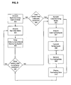
- step 300 based on whether the barcode scanner 108 has been removed from the cradle 110 (first embodiment) or whether an object is within a predetermined distance range from the barcode scanner 108 (second embodiment), the process proceeds to steps 302 or 306. If the scanner 112 has not been removed from the cradle 110 or an object is not within a predetermined distance range from the barcode scanner 108, step 302 places the barcode scanner 108 in the real-time video capture mode.
- step 303 acquires real-time video and step 304 relays the real-time video to a video surveillance monitoring system of the type known in the prior art.
- the process then proceeds to step 305 where in accordance to whether the barcode scanner 108 is within the cradle 110 or whether an object is within the predetermined distance range of the barcode scanner 108, the process proceeds to step 303 or step 306.
- step 306 places the barcode scanner 108 in the barcode imaging and decoding mode.
- Step 307 acquires an image of the barcode using the imager 200 of the barcode scanner 108.
- the data encoded by the acquired image is then decoded by the processing unit 208 in step 308 using at least one decoding algorithm for decoding at least one code symbology as known in the art.
- the acquired image or data encoded therein is transmitted via the communications circuitry 209 to a processing unit located externally from the barcode scanner 108, such as a processing unit within the payment processing apparatus 114 or the cradle 110, for the decoding of the barcode data.
- a processing unit located externally from the barcode scanner 108 such as a processing unit within the payment processing apparatus 114 or the cradle 110, for the decoding of the barcode data.
- the decoded barcode data is then used to retrieve item and price information, as well as other information, in step 309.
- the data is retrieved by accessing a database storing such information.
- the retrieved information is then displayed on the monitor 112 in step 310.
- the process then proceeds to step 305.
- the switching mechanism can include other types of switching configurations, such as placing a mechanical lever within the cradle for effecting switching between the two modes when the lever is moved from one position to another position when the barcode scanner is placed within the cradle.
- the switching mechanism can also include a manual switch provided on the barcode scanner which when moved from one position to another position sends a signal to the processing unit for switching between the two modes.
Landscapes
- Physics & Mathematics (AREA)
- Engineering & Computer Science (AREA)
- Electromagnetism (AREA)
- Artificial Intelligence (AREA)
- Toxicology (AREA)
- General Health & Medical Sciences (AREA)
- Health & Medical Sciences (AREA)
- Computer Vision & Pattern Recognition (AREA)
- General Physics & Mathematics (AREA)
- Theoretical Computer Science (AREA)
- Closed-Circuit Television Systems (AREA)
- Cash Registers Or Receiving Machines (AREA)
- Studio Devices (AREA)
Description
- The present disclosure relates generally to barcode imaging/decoding systems and real-time video capture systems for video surveillance purposes. In particularly, the present disclosure relates to a combination barcode imaging/decoding and real-time video capture system. More particularly, the present disclosure relates to a point-of-sale barcode imaging/decoding and real-time video capture system.
- Point-of-sale (POS) systems, such as self-checkout POS stations which enable consumers to scan product barcodes and purchase products without the aid of a sales clerk, are widely implemented at point-of-sale locations in many retail outlets. The POS locations are generally monitored by video surveillance systems having a plurality of video cameras to deter theft of products by consumers using self-checkout POS stations or to aid in apprehending thieves who commit robbery by accosting a retail clerk at a POS station.
- Sometimes in an effort to reduce costs, the retail outlets employ a single video camera for capturing real-time video of a field of view which can include within it several POS stations. The real-time video is typically transmitted to a video surveillance monitoring system for enabling security personnel to conduct video surveillance. In order for each POS station to be in the field of view or line-of-sight of the video camera, the single video camera is positioned at a substantial distance from each POS station. It has been observed that an individual at a self-checkout POS station who intends to steal items is aware of the video camera in the line-of-sight of the POS station. The individual typically positions himself in a manner which blocks the line-of-sight and security personnel monitoring the incoming real-time video from the video camera are unable to detect whether the individual is stealing items.
-
US-A-6,726,094 discloses a customer self-service terminal for use in conducting retail transactions. The terminal includes a camera having multimode image capability. When a customer wishes to conduct a transaction, the camera is used to scan product barcodes. The camera is set to capture an image of a barcode for extraction of data contained in the barcode. When all desired products have been scanned, the camera is used to record steps in the tendering of payment. The customer presents a financial identification card such as a credit or debit card and swipes it through a magnetic stripe reader. The customer then places the card in the field of view of the camera which is set to a video graphic mode to capture an image of the card for storage. The customer is then presented with a transaction document for signing. The camera is set to a live video mode to record the act of signing. After the transaction document has been signed, the camera captures an image of the signature. The captured images are associated with the transaction record and stored along with the transaction record, and the transaction is completed. The camera may also be set to provide a live video feed, which may be used sent to a remote security station for monitoring by a store employee. -
US-A-5,682,030 discloses a method and apparatus for decoding bar code data from a video signal, wherein a bar code within a composite video signal may be detected and decoded. The composite video signal is converted into a form suitable for providing to a bar code decoder, in order that any bar code within the video signal may be decoded by the decoder. The output of the bar code decoder may thereafter be provided to, for example, a computer for the further processing. The composite video signal which is decoded may be generated by a video camera, a video tape recorder, a television signal, or any other source which generates such a video signal. Bar codes detected by video cameras in different environments may be decoded and processed by a computer. -
EP-A-0 873 013 discloses a process which allows an image capturing apparatus to be integrated with a personal computer to continuously display a video image of the imaging apparatus. Upon proper input by a user, or automatically after a timed interval, a snapshot of the video image is captured.
An autodiscrimination process of the captured video image automatically decodes any bar-coded information present in the captured image and outputs the information. - A need therefore exists for a combination barcode imaging/decoding and real-time video capture system which can be positioned at the POS location to perform the functions of barcode imaging and decoding, and real-time video capture for video surveillance purposes. A need also exists for a POS station, such as a self-checkout POS station, having an imager or imaging sensor which performs the functions of barcode imaging and decoding, and real-time video capture.
- The present disclosure provides a combination barcode imaging/decoding and real-time video capture system, as set forth in claim 1. The system is configured for being implemented at a POS location for performing the functions of barcode imaging and decoding, and real-time video capture for video surveillance purposes. The system includes an imager or imaging sensor as known in the art and a switching mechanism for switching and operating the imager between a barcode imaging and decoding mode for imaging and decoding barcodes positioned in proximity to the imager, and a real-time video capture mode for capturing real-time video for video surveillance purposes. The present disclosure further provides a POS station, such as a self-checkout POS station, having the features of the combination system.
- The present disclosure further provides a method of operating a combination barcode imaging/decoding and real-time video capture system as set forth in claim 9. In one method of operation, the combination barcode imaging/decoding and real-time video capture system is selectively operated or switched between the two modes by detecting whether a barcode scanner housing the imager is positioned within a cradle. If the barcode scanner is positioned within the cradle, a signal is transmitted to a processing unit within the barcode scanner to operate the scanner in the real-time video capture mode. If the barcode scanner is not positioned within the cradle, the signal is not transmitted to the processing unit and the scanner is operated in a barcode imaging and decoding mode.
- In another method of operation, the combination barcode imaging/decoding and real-time video capture system is selectively operated or switched between two modes of operation by determining if a barcode is positioned in proximity to the imager using conventional image processing techniques. A proximity sensor as known in the art is used for determining if an object is positioned within a predetermined distance range from the barcode scanner. If it is determined that an object is positioned within the predetermined distance range from the barcode scanner, the processing unit freezes a real-time image of the real-time video images relayed by the imager to the processing unit.
- The processing unit then determines using conventional image processing techniques whether the image includes a barcode. If it is determined that the image includes a barcode, the processing unit switches the mode of operation from the real-time video capture mode to the barcode imaging and decoding mode, in order to re-image and decode the barcode. It is contemplated that the image relayed to the processing unit can be used decoding the barcode without re-imaging the barcode.
- In both methods of operation, the imaged barcode data is relayed to the processing unit of the barcode scanner or some other processing unit of the combination barcode imaging/decoding and real-time video capture system for decoding and thereby, determining the type of item, the price and/or other information for the scanned item as known in the art. A total cost for all the scanned items is then tallied by the system and displayed on a monitor.
- These and other features, aspects, and advantages of the present invention will become better understood with regard to the following description, appended claims, and accompanying drawings wherein:
-
FIG. 1 is a schematic illustrating a combination barcode imaging/decoding and real-time video capture system in accordance with the present disclosure; -
FIG. 2 is a schematic illustrating a barcode scanner and a cradle for placing the barcode scanner therein in accordance with the present disclosure; -
FIG. 2A is a schematic illustrating a barcode scanner having a proximity sensor in accordance with the present disclosure; and -
FIG. 3 is a flowchart illustrating a method of operation for the disclosed system in accordance with the present disclosure. - As described in detail in this section, the present disclosure provides a combination or integrated barcode imaging/decoding and real-time video capture system. The system is configured for being implemented at a POS location for performing the functions of barcode imaging and decoding, and real-time video capture for video surveillance purposes. The system includes an imager or imaging sensor as known in the art and a switching mechanism for switching and operating the imager between a barcode imaging and decoding mode for imaging and decoding barcodes positioned in proximity to the imager, and a real-time video capture mode for capturing real-time video for video surveillance purposes. The present disclosure further provides a POS station, such as a self-checkout POS station, having the features of the combination system.
- An exemplary embodiment of the combination system having a POS station is shown by
FIG. 1 and designated generally byreference numeral 100. The POS station is of the self-checkout type which may include a weighing station and electronic article surveillance (EAS) system as known in the art. It is contemplated that other types of POS stations can be used with thesystem 100 of the present disclosure besides self-checkout POS stations. InFIG. 1 , the POS station is designated byreference numeral 102. - The
POS station 102 includes a holdingarea 104 for placing items prior to scanning their respective barcodes. Acheckout area 106 is provided adjacent to the holdingarea 104 having a workingsurface 105. The workingsurface 105 includes abarcode scanner 108 having an imager orimaging sensor 200, such as a charge-coupled device (CCD), and alens assembly 202 housed within ahousing 204. Theimager 200 is preferably an imaging engine configured and dimensioned to fit within a predetermined form factor of the barcode scanner. - The
barcode scanner 108 further includes a triggering mechanism 206 (seeFIGs. 2 and2A ) for actuating a barcode imaging and decoding operation as known in the art and aprocessing unit 208 having at least one processor for executing a set of programmable instructions for operating thebarcode scanner 108 and performing the functions described herein for thebarcode scanner 108. Thebarcode scanner 108 further includescommunication circuitry 209 and abattery pack 210 for enabling wireless operation of thebarcode scanner 108. - The
processing unit 208 of thebarcode scanner 108 in accordance with the present disclosure is capable of operating thebarcode scanner 108 between a barcode imaging and decoding mode and a real-time video capture mode. The real-time video capture mode is similar in operation as that of a video camera, where moving video images are captured. - In one embodiment of the
barcode scanner 108, switching between the two modes of operation is facilitated by the use of acradle 110 configured and dimensioned for positioning thebarcode scanner 108 therein. Thecradle 110 includes a switching mechanism for transmitting a signal to theprocessing unit 208 for effecting switching between the two modes of operation according to whether thebarcode scanner 108 is positioned within thecradle 110. - With reference to
FIG. 2 , the switching mechanism includes adata interface connector 212 having data interface pins for connecting to adriver 214 on thebarcode scanner 108. Upon the pins of thedata interface connector 212 being connected to thedriver 214, a signal is relayed from thedata interface connector 212 to thedriver 214, and subsequently from thedriver 214 to theprocessing unit 208. The signal instructs theprocessing unit 208 to switch the mode of operation of thebarcode scanner 108 from the barcode imaging and decoding mode to the real-time video capture mode. - One or more additional signals can be related to the
processing unit 208 from thedata interface connector 212. The signals preferably provide software updates, including symbology decoding algorithms for one- and two-dimensional symbologies for programming or reprogramming a decoding unit of theprocessing unit 208. - The real-time video captured during the operation of the
barcode scanner 108 in the real-time video capture mode is transmitted to a video surveillance monitoring system via acable 216 connected to thecradle 110. Accordingly, when a user simply drops thebarcode scanner 108 within thecradle 110, the barcode scanner automatically becomes a video camera and thereby captures real-time video which is transmitted to the video surveillance monitoring system or other type of system. It is contemplated that thecradle 110 further includes a battery charger for charging thebattery pack 210 when thebarcode scanner 108 is positioned within thecradle 110. - On the other hand, when the user picks up the
barcode scanner 108, thedata interface connector 212 is disconnected from thedriver 214 of thebarcode scanner 108 and the signal is no longer relayed to theprocessing unit 208. Theprocessing unit 208 then switches the barcode scanner to the barcode imaging and decoding mode. During this mode, thebarcode scanner 108 is used to image and decode a barcode and transmit the decoded barcode data via thecommunications circuitry 209 to thecradle 110. Thecradle 110 in turn relays the decoded data via thecable 216 to amonitor 112 for display. The display can include item and price information with respect to the scanned item. - In an alternate embodiment of the
barcode scanner 108, as shown byFIG. 2A , thebarcode scanner 108 is continuously operated in the real-time video capture mode unless it is determined that a barcode is positioned in the field of view of thebarcode scanner 108 and within a predetermined distance range from thebarcode scanner 108. In this embodiment, the switching mechanism includes theprocessing unit 208 and aproximity sensor 111 positioned on thebarcode scanner 108 for sensing whether an object is within the predetermined distance range from thebarcode scanner 108. If an object is sensed to be within the predetermined distance range, e.g., within 10 centimeters, from thebarcode scanner 108 by theproximity sensor 111, theproximity sensor 111 transmits a signal to theprocessing unit 208 of thebarcode scanner 108. Upon receiving the signal, theprocessing unit 208 freezes a real-time image of the real-time video images relayed by the imager to theprocessing unit 208. - The
processing unit 208 then determines using conventional image processing techniques, including techniques for determining whether an image includes a barcode, whether the real-time image includes a barcode. If the image is determined to include a barcode, theprocessing unit 208 switches the mode of operation of thebarcode scanner 108 from the real-time video capture mode to the barcode imaging and decoding mode, in order to re-image and decode the barcode. The processing unit then automatically switches the barcode scanned. 108 back to the real-time video capture mode. It is contemplated that the image relayed to theprocessing unit 208 can be used for decoding the barcode without re-imaging the barcode. It is also contemplated that thebarcode scanner 108 of this embodiment is continuously operated in the real-time video capture mode, but real-time images of the real-time video images relayed by the imager to theprocessing unit 208 are frozen and used for decoding the barcodes. - If it is determined that the image relayed to the processing unit does not include a barcode, the
processing unit 208 does not switch the operating mode of thebarcode scanner 108 from the real-time video capture mode to the barcode imaging and decoding mode. - With reference to
FIG. 1 , the workingsurface 105 of thesystem 100 further includes apayment processing apparatus 114 connected to thebarcode scanner 108 and themonitor 112 for enabling a consumer to pay for the items scanned. Thepayment processing apparatus 114, as known in the art, includes a keypad for communicating with theapparatus 114 and a slot for swiping a credit and debit card for effecting payment. Thepayment processing apparatus 114 can further include a slot for accepting money and a slot for providing change to the consumer.
Adjacent to the workingsurface 105 is baggingstation 116 having at least onebag 118 for enabling the consumer to bag each item after it is scanned. - With reference to
FIG. 3 , there is shown a flowchart including steps for operating thebarcode scanner 108 of thesystem 100 in accordance with the present disclosure. Instep 300, based on whether thebarcode scanner 108 has been removed from the cradle 110 (first embodiment) or whether an object is within a predetermined distance range from the barcode scanner 108 (second embodiment), the process proceeds tosteps 302 or 306. If thescanner 112 has not been removed from thecradle 110 or an object is not within a predetermined distance range from thebarcode scanner 108, step 302 places thebarcode scanner 108 in the real-time video capture mode. - While the
barcode scanner 108 is operating in the real-time video capture mode,step 303 acquires real-time video and step 304 relays the real-time video to a video surveillance monitoring system of the type known in the prior art. The process then proceeds to step 305 where in accordance to whether thebarcode scanner 108 is within thecradle 110 or whether an object is within the predetermined distance range of thebarcode scanner 108, the process proceeds to step 303 or step 306. - If the
barcode scanner 108 has been removed from thecradle 110 or an object is within a predetermined distance range from thebarcode scanner 108, then the process proceeds to step 306 fromstep 300. Step 306 places thebarcode scanner 108 in the barcode imaging and decoding mode. Step 307 acquires an image of the barcode using theimager 200 of thebarcode scanner 108. The data encoded by the acquired image is then decoded by theprocessing unit 208 instep 308 using at least one decoding algorithm for decoding at least one code symbology as known in the art. It is contemplated that the acquired image or data encoded therein is transmitted via thecommunications circuitry 209 to a processing unit located externally from thebarcode scanner 108, such as a processing unit within thepayment processing apparatus 114 or thecradle 110, for the decoding of the barcode data. - The decoded barcode data is then used to retrieve item and price information, as well as other information, in
step 309. The data is retrieved by accessing a database storing such information. The retrieved information is then displayed on themonitor 112 instep 310. The process then proceeds to step 305. - In is contemplated that the switching mechanism can include other types of switching configurations, such as placing a mechanical lever within the cradle for effecting switching between the two modes when the lever is moved from one position to another position when the barcode scanner is placed within the cradle. The switching mechanism can also include a manual switch provided on the barcode scanner which when moved from one position to another position sends a signal to the processing unit for switching between the two modes. Accordingly, the described embodiments of the present invention are intended to be illustrative rather than restrictive, and are not intended to represent every embodiment of the present invention. Various modifications and variations can be made without departing from the scope of the invention being determined by the following claims.
Claims (15)
- A combination barcode imager/decoder and video capture system (100) comprising:a barcode scanner (108) having an imager (200) wherein the barcode scanner (108) is operated in at least two modes, and when operated in each mode of the at least two modes the imager (200) generates at least one image; anda switching mechanism (206) in operative communication with a processing unit (208) of the barcode scanner (108), said switching mechanism (206) being configured to generate and transmit a signal to the processing unit (208) for effecting a switching of a mode of operation of the barcode scanner (108), between a video capture mode for generating a stream of images and a barcode imaging and decoding mode for generating at least one image including a barcode and for processing the imaged barcode, and wherein processing of a barcode for the purpose of decoding thereof is performed only when operating the barcode scanner (108) in the barcode imaging and decoding mode of the two modes which include the video capture mode and the barcode imaging and decoding mode;characterized by:a proximity sensor (111) for sensing when an object to be imaged is positioned within a predetermined distance range of the imager (200);circuitry (208) for freezing at least one image captured during operation of the imager (200) in the video capture mode upon sensing that the object is positioned within the predetermined distance range; anda processor (208) for determining whether an image of the frozen at least one image includes a barcode, wherein if the processor determines that the at least one image includes a barcode, the processor switches the mode of operation of the imager (200) from the video capture mode to a barcode imaging and decoding mode.
- The combination system according to Claim 1, further comprising a cradle (110) for positioning the barcode scanner (108) therein, and wherein the switching mechanism (206) comprises a data interface connector (212) within the cradle (110) for interfacing with the barcode scanner (108) when the barcode scanner (108) is positioned within the cradle (110).
- The combination system according to Claim 2, wherein at least one signal is communicated to the processing unit (208) from the data interface connector (212) for switching the mode of operation of the barcode scanner (108) from the barcode imaging and decoding mode to the video capture mode.
- The combination system according to Claim 1, further comprising communication means (216) for transmitting video images to a surveillance system during operation of the barcode scanner (108) in the video capture mode.
- The combination system according to Claim 1, further comprising:a monitor (112) for displaying information acquired due to the decoding of at least one barcode during operation of the barcode scanner (108) in the barcode imaging and decoding mode; anda payment processing apparatus (114) for effecting payment for items scanned by the barcode scanner (108) during operation of the barcode scanner (108) in the barcode imaging and decoding mode.
- The combination system according to Claim 1, wherein the combination system (100) is a point-of-sale station (102).
- The combination system according to Claim 1, wherein during operation of the barcode scanner (108) in the video capture mode, the stream of images includes real-time video images corresponding to the field of view of the barcode scanner (108).
- A method of operating a combination barcode imager/decoder and real-time video capture system (100) having a processing unit (208), said method comprising:operating (302-305) a barcode scanner (108) of the system in a video capture mode for capturing real-time video images when the barcode scanner (108) is positioned at a first location; andoperating (306-310) a barcode scanner (108) of the system in a barcode imaging and decoding mode for imaging and decoding a barcode when the barcode scanner (108) is positioned at a second location, different from said first location, wherein the mode of operation of the system is selected (300) in accordance with the location of the barcode scanner (108), the imaging when operating in the first and second modes is performed by an imager (200) of the barcode scanner (108), and processing of a barcode for the purpose of decoding thereof is performed only when operating the barcode scanner (108) in the barcode imaging and decoding mode of the two modes which include the video capture mode and the barcode imaging and decoding mode;sensing that an object is positioned within a predetermined distance range from the imager (200) of the system;freezing an image from the video images responsive to the sensing of the object;determining whether the frozen image includes a barcode;automatically switching from the video capture mode to the barcode imaging and decoding mode responsive to the determining that the frozen image includes the barcode;operating the system in the barcode imaging and decoding mode upon switching, including decoding the barcode; andtransmitting the video images to a surveillance system during operation of the system in the video capture mode.
- The method according to Claim 8, further comprising displaying (310) information acquired due to the decoding of at least one barcode during operation of the barcode scanner (108) in the barcode imaging and decoding mode.
- The method according to Claim 8, wherein the combination system (100) is a point-of-sale station (102).
- The method according to Claim 8, wherein during operation of the barcode scanner (108) in the video capture mode, the barcode scanner (108) captures real-time video images corresponding to the field of view of the barcode scanner (108).
- The method according to Claim 8, wherein when the imager (200) is switched to the barcode imaging and decoding mode the imager re-images the object and decodes a barcode included in an image acquired via the re-imaging.
- The method according to Claim 8, wherein the decoding is performed upon the frozen image.
- The method according to Claim 13, wherein after the decoding, the method comprises the step of automatically switching from the barcode imaging and decoding mode to the video capture mode.
- The method according to Claim 8, wherein the combination system continuously captures images in the video capture mode during the sensing, freezing, determining and decoding steps.
Applications Claiming Priority (2)
| Application Number | Priority Date | Filing Date | Title |
|---|---|---|---|
| US10/929,936 US7293711B2 (en) | 2004-08-30 | 2004-08-30 | Combination barcode imaging/decoding and real-time video capture system |
| PCT/US2005/029855 WO2006026247A1 (en) | 2004-08-30 | 2005-08-22 | Combination barcode imaging/decoding and real-time video capture system |
Publications (2)
| Publication Number | Publication Date |
|---|---|
| EP1851677A1 EP1851677A1 (en) | 2007-11-07 |
| EP1851677B1 true EP1851677B1 (en) | 2010-04-07 |
Family
ID=35432100
Family Applications (1)
| Application Number | Title | Priority Date | Filing Date |
|---|---|---|---|
| EP05791691A Expired - Lifetime EP1851677B1 (en) | 2004-08-30 | 2005-08-22 | Combination barcode imaging/decoding and real-time video capture system |
Country Status (6)
| Country | Link |
|---|---|
| US (1) | US7293711B2 (en) |
| EP (1) | EP1851677B1 (en) |
| JP (1) | JP4559483B2 (en) |
| CN (1) | CN101128836A (en) |
| DE (1) | DE602005020517D1 (en) |
| WO (1) | WO2006026247A1 (en) |
Families Citing this family (60)
| Publication number | Priority date | Publication date | Assignee | Title |
|---|---|---|---|---|
| US7253919B2 (en) * | 2000-11-30 | 2007-08-07 | Ricoh Co., Ltd. | Printer with embedded retrieval and publishing interface |
| US8539344B2 (en) | 2001-11-19 | 2013-09-17 | Ricoh Company, Ltd. | Paper-based interface for multimedia information stored by multiple multimedia documents |
| US7424129B2 (en) * | 2001-11-19 | 2008-09-09 | Ricoh Company, Ltd | Printing system with embedded audio/video content recognition and processing |
| US7743347B2 (en) * | 2001-11-19 | 2010-06-22 | Ricoh Company, Ltd. | Paper-based interface for specifying ranges |
| US7703044B2 (en) | 2001-11-19 | 2010-04-20 | Ricoh Company, Ltd. | Techniques for generating a static representation for time-based media information |
| US7861169B2 (en) | 2001-11-19 | 2010-12-28 | Ricoh Co. Ltd. | Multimedia print driver dialog interfaces |
| US20040181815A1 (en) * | 2001-11-19 | 2004-09-16 | Hull Jonathan J. | Printer with radio or television program extraction and formating |
| US7149957B2 (en) | 2001-11-19 | 2006-12-12 | Ricoh Company, Ltd. | Techniques for retrieving multimedia information using a paper-based interface |
| US7788080B2 (en) | 2001-11-19 | 2010-08-31 | Ricoh Company, Ltd. | Paper interface for simulation environments |
| US7747655B2 (en) | 2001-11-19 | 2010-06-29 | Ricoh Co. Ltd. | Printable representations for time-based media |
| US7275159B2 (en) | 2003-08-11 | 2007-09-25 | Ricoh Company, Ltd. | Multimedia output device having embedded encryption functionality |
| US7508535B2 (en) | 2003-09-25 | 2009-03-24 | Ricoh Co., Ltd. | Stand alone multimedia printer with user interface for allocating processing |
| US7440126B2 (en) * | 2003-09-25 | 2008-10-21 | Ricoh Co., Ltd | Printer with document-triggered processing |
| US7864352B2 (en) * | 2003-09-25 | 2011-01-04 | Ricoh Co. Ltd. | Printer with multimedia server |
| US7528976B2 (en) * | 2003-09-25 | 2009-05-05 | Ricoh Co., Ltd. | Stand alone printer with hardware/software interfaces for sharing multimedia processing |
| US20050071746A1 (en) * | 2003-09-25 | 2005-03-31 | Hart Peter E. | Networked printer with hardware and software interfaces for peripheral devices |
| US7573593B2 (en) * | 2003-09-25 | 2009-08-11 | Ricoh Company, Ltd. | Printer with hardware and software interfaces for media devices |
| US7528977B2 (en) | 2003-09-25 | 2009-05-05 | Ricoh Co., Ltd. | Printer with hardware and software interfaces for peripheral devices |
| JP2005108230A (en) | 2003-09-25 | 2005-04-21 | Ricoh Co Ltd | Audio / video content recognition / processing function built-in printing system |
| US7570380B2 (en) * | 2003-09-25 | 2009-08-04 | Ricoh Company, Ltd. | Printer user interface |
| US20050071763A1 (en) * | 2003-09-25 | 2005-03-31 | Hart Peter E. | Stand alone multimedia printer capable of sharing media processing tasks |
| US20050068573A1 (en) * | 2003-09-25 | 2005-03-31 | Hart Peter E. | Networked printing system having embedded functionality for printing time-based media |
| US8077341B2 (en) | 2003-09-25 | 2011-12-13 | Ricoh Co., Ltd. | Printer with audio or video receiver, recorder, and real-time content-based processing logic |
| US7505163B2 (en) * | 2003-09-25 | 2009-03-17 | Ricoh Co., Ltd. | User interface for networked printer |
| US8274666B2 (en) * | 2004-03-30 | 2012-09-25 | Ricoh Co., Ltd. | Projector/printer for displaying or printing of documents |
| US7603615B2 (en) | 2004-03-30 | 2009-10-13 | Ricoh Co., Ltd. | Multimedia projector-printer |
| US7551312B1 (en) | 2005-03-17 | 2009-06-23 | Ricoh Co., Ltd. | Annotable document printer |
| JP2007174444A (en) * | 2005-12-23 | 2007-07-05 | Brother Ind Ltd | Network scanner and network scanner system |
| US7866546B1 (en) | 2006-04-21 | 2011-01-11 | Pan-Oston | Automated checkout unit and method of use thereof |
| CN101682696B (en) * | 2007-06-04 | 2012-04-18 | 夏普株式会社 | Mobile terminal, mobile terminal control method |
| US8662397B2 (en) * | 2007-09-27 | 2014-03-04 | Symbol Technologies, Inc. | Multiple camera imaging-based bar code reader |
| US10540861B2 (en) * | 2007-12-20 | 2020-01-21 | Ncr Corporation | Sustained authentication of a customer in a physical environment |
| US8270303B2 (en) | 2007-12-21 | 2012-09-18 | Hand Held Products, Inc. | Using metadata tags in video recordings produced by portable encoded information reading terminals |
| JP4436872B2 (en) * | 2008-01-24 | 2010-03-24 | 東芝テック株式会社 | Data code reader |
| US8109439B2 (en) * | 2008-04-08 | 2012-02-07 | Toshiba Tec Kabushiki Kaisha | Commodity registration processing apparatus |
| US20100102129A1 (en) * | 2008-10-29 | 2010-04-29 | Symbol Technologies, Inc. | Bar code reader with split field of view |
| US8479996B2 (en) * | 2008-11-07 | 2013-07-09 | Symbol Technologies, Inc. | Identification of non-barcoded products |
| US8079523B2 (en) | 2008-12-15 | 2011-12-20 | Symbol Technologies, Inc. | Imaging of non-barcoded documents |
| US20100198876A1 (en) | 2009-02-02 | 2010-08-05 | Honeywell International, Inc. | Apparatus and method of embedding meta-data in a captured image |
| CN101854478B (en) * | 2009-03-31 | 2011-12-07 | 上海先达企业发展有限公司 | Method for realizing automatic shooting by utilizing bar code reader field depth characteristic |
| US8879639B2 (en) * | 2011-01-31 | 2014-11-04 | Hand Held Products, Inc. | Adaptive video capture decode system |
| DE102011010722B4 (en) * | 2011-02-09 | 2024-10-10 | Testo Ag | Measuring instrument set and procedure for documenting a measurement |
| US8469272B2 (en) | 2011-03-29 | 2013-06-25 | Metrologic Instruments, Inc. | Hybrid-type bioptical laser scanning and imaging system supporting digital-imaging based bar code symbol reading at the surface of a laser scanning window |
| JP2013088952A (en) * | 2011-10-14 | 2013-05-13 | Keyence Corp | Optical information reading apparatus |
| JP5372191B2 (en) * | 2012-01-30 | 2013-12-18 | 東芝テック株式会社 | Product reading apparatus and product reading program |
| US9113235B2 (en) * | 2012-11-14 | 2015-08-18 | Symbol Technologies, Llc | Device and method for functionality sequencing |
| US9165173B2 (en) * | 2013-05-29 | 2015-10-20 | Ncr Corporation | Security method using an imaging barcode reader |
| US9613332B2 (en) | 2014-07-31 | 2017-04-04 | Blue Point Tec LLC | Devices, systems and methods for tracking and auditing shipment items |
| JP6467180B2 (en) * | 2014-10-01 | 2019-02-06 | シャープ株式会社 | Object detection device |
| US9406059B1 (en) * | 2015-03-25 | 2016-08-02 | Ncr Corporation | Checkout imaging mechanism |
| GB2537405B (en) * | 2015-04-16 | 2019-09-18 | Everseen Ltd | A POS Terminal |
| CN105701433B (en) * | 2015-12-30 | 2019-01-15 | 联想(北京)有限公司 | A kind of information processing method and electronic equipment |
| JP6730079B2 (en) * | 2016-04-28 | 2020-07-29 | 東芝テック株式会社 | Monitoring device and program |
| US11095801B2 (en) * | 2016-08-30 | 2021-08-17 | Ncr Corporation | Scanner with independent integrated network video capabilities |
| JP6708095B2 (en) * | 2016-10-24 | 2020-06-10 | カシオ計算機株式会社 | Bar code reader and program |
| JP7166767B2 (en) | 2017-05-25 | 2022-11-08 | キヤノン株式会社 | Equipment, manufacturing methods and systems |
| EP3407598B1 (en) * | 2017-05-25 | 2021-12-08 | Canon Kabushiki Kaisha | Image capturing apparatus, system, and method |
| CN108833786B (en) * | 2018-06-29 | 2022-04-22 | 联想(北京)有限公司 | Mode control method and electronic equipment |
| JP7117969B2 (en) * | 2018-10-15 | 2022-08-15 | 東芝テック株式会社 | reader and program |
| FR3092421B1 (en) * | 2019-01-31 | 2022-07-22 | Saint Gobain | Method for manually reading a code, and reading device for implementing said method |
Family Cites Families (9)
| Publication number | Priority date | Publication date | Assignee | Title |
|---|---|---|---|---|
| US4958064A (en) * | 1989-01-30 | 1990-09-18 | Image Recognition Equipment Corporation | Bar code locator for video scanner/reader system |
| US5616908A (en) * | 1991-09-17 | 1997-04-01 | Metrologic Instruments, Inc. | Automatic countertop laser scanner with flickering laser scanner beam for improved visibility thereof during bar code symbol reading |
| JP3482229B2 (en) * | 1993-11-19 | 2003-12-22 | 株式会社日立製作所 | Checkout device |
| AU6267294A (en) | 1993-02-02 | 1994-08-29 | Label Vision Systems, Inc. | Method and apparatus for decoding bar code data from a video signal and applications thereof |
| EP0873013A3 (en) | 1996-11-05 | 2001-01-03 | Welch Allyn, Inc. | Decoding of real time video imaging |
| JP2000259239A (en) * | 1999-03-12 | 2000-09-22 | Omron Corp | Logging device, logging system and logging report |
| JP4325018B2 (en) * | 1999-05-24 | 2009-09-02 | 株式会社竹屋 | Amusement hall monitoring device |
| US6726094B1 (en) * | 2000-01-19 | 2004-04-27 | Ncr Corporation | Method and apparatus for multiple format image capture for use in retail transactions |
| US6772950B2 (en) * | 2002-09-19 | 2004-08-10 | Symbol Technologies, Inc. | System and method for an image capturing network |
-
2004
- 2004-08-30 US US10/929,936 patent/US7293711B2/en not_active Expired - Lifetime
-
2005
- 2005-08-22 DE DE602005020517T patent/DE602005020517D1/en not_active Expired - Lifetime
- 2005-08-22 WO PCT/US2005/029855 patent/WO2006026247A1/en not_active Ceased
- 2005-08-22 JP JP2007530034A patent/JP4559483B2/en not_active Expired - Lifetime
- 2005-08-22 EP EP05791691A patent/EP1851677B1/en not_active Expired - Lifetime
- 2005-08-22 CN CNA2005800336365A patent/CN101128836A/en active Pending
Also Published As
| Publication number | Publication date |
|---|---|
| US20060043193A1 (en) | 2006-03-02 |
| US7293711B2 (en) | 2007-11-13 |
| EP1851677A1 (en) | 2007-11-07 |
| DE602005020517D1 (en) | 2010-05-20 |
| WO2006026247B1 (en) | 2006-06-15 |
| JP2008511920A (en) | 2008-04-17 |
| JP4559483B2 (en) | 2010-10-06 |
| CN101128836A (en) | 2008-02-20 |
| WO2006026247A1 (en) | 2006-03-09 |
Similar Documents
| Publication | Publication Date | Title |
|---|---|---|
| US7293711B2 (en) | Combination barcode imaging/decoding and real-time video capture system | |
| US8876001B2 (en) | Methods and apparatus for image recognition in checkout verification | |
| US6726094B1 (en) | Method and apparatus for multiple format image capture for use in retail transactions | |
| US20240086886A1 (en) | Systems and Methods for Data Capture Device Selection from Within Data Capture Device Repository | |
| US7114656B1 (en) | Fixed self-checkout station with cradle for communicating with portable self-scanning units | |
| US7883012B2 (en) | Integrated data reader and bottom-of-basket item detector | |
| US8424761B2 (en) | Commodity code reading apparatus and commodity code reading method | |
| US20030018897A1 (en) | Video identification verification system and method for a self-checkout system | |
| US20120127314A1 (en) | Item identification using video recognition to supplement bar code or rfid information | |
| US10043119B1 (en) | Item security system and method of verifying items selected for purchase at a checkout station | |
| JP2003187335A (en) | Automatic merchandise adjustment system, merchandise adjustment device and merchandise cart | |
| KR20030076038A (en) | Digital video recoding system and method by POS data | |
| US20250037102A1 (en) | Weight Check for Verification of Ticket Switching | |
| JPH08147560A (en) | Automatic commodity adjustment system | |
| EP2905736A1 (en) | Reading apparatus | |
| JP2025120363A (en) | Merchandise sales data processing device and program | |
| JP6853973B2 (en) | Monitoring system using an electronic payment terminal | |
| US9165173B2 (en) | Security method using an imaging barcode reader | |
| KR200279477Y1 (en) | Digital video recording system by POS data | |
| KR20120071502A (en) | Store watching system and method using tablet pc | |
| US8448861B2 (en) | Code reading apparatus and control method | |
| WO2025187297A1 (en) | Information processing device and determination method | |
| JP2026066898A (en) | System, sales data processing device, and program |
Legal Events
| Date | Code | Title | Description |
|---|---|---|---|
| PUAI | Public reference made under article 153(3) epc to a published international application that has entered the european phase |
Free format text: ORIGINAL CODE: 0009012 |
|
| 17P | Request for examination filed |
Effective date: 20070222 |
|
| AK | Designated contracting states |
Kind code of ref document: A1 Designated state(s): DE FR GB |
|
| 17Q | First examination report despatched |
Effective date: 20071024 |
|
| DAX | Request for extension of the european patent (deleted) | ||
| RBV | Designated contracting states (corrected) |
Designated state(s): DE FR GB |
|
| RBV | Designated contracting states (corrected) |
Designated state(s): DE FR GB |
|
| GRAP | Despatch of communication of intention to grant a patent |
Free format text: ORIGINAL CODE: EPIDOSNIGR1 |
|
| GRAS | Grant fee paid |
Free format text: ORIGINAL CODE: EPIDOSNIGR3 |
|
| GRAA | (expected) grant |
Free format text: ORIGINAL CODE: 0009210 |
|
| AK | Designated contracting states |
Kind code of ref document: B1 Designated state(s): DE FR GB |
|
| REG | Reference to a national code |
Ref country code: GB Ref legal event code: FG4D |
|
| REF | Corresponds to: |
Ref document number: 602005020517 Country of ref document: DE Date of ref document: 20100520 Kind code of ref document: P |
|
| REG | Reference to a national code |
Ref country code: DE Ref legal event code: R096 Ref document number: 602005020517 Country of ref document: DE Effective date: 20100520 |
|
| PLBE | No opposition filed within time limit |
Free format text: ORIGINAL CODE: 0009261 |
|
| STAA | Information on the status of an ep patent application or granted ep patent |
Free format text: STATUS: NO OPPOSITION FILED WITHIN TIME LIMIT |
|
| 26N | No opposition filed |
Effective date: 20110110 |
|
| REG | Reference to a national code |
Ref country code: DE Ref legal event code: R097 Ref document number: 602005020517 Country of ref document: DE Effective date: 20110110 |
|
| REG | Reference to a national code |
Ref country code: DE Ref legal event code: R082 Ref document number: 602005020517 Country of ref document: DE Representative=s name: LKGLOBAL | LORENZ & KOPF PARTG MBB PATENTANWAE, DE Ref country code: DE Ref legal event code: R082 Ref document number: 602005020517 Country of ref document: DE Representative=s name: SCHUMACHER & WILLSAU PATENTANWALTSGESELLSCHAFT, DE Ref country code: DE Ref legal event code: R082 Ref document number: 602005020517 Country of ref document: DE Representative=s name: KOPF, KORBINIAN, DIPL.-ING.UNIV., MA, DE Ref country code: DE Ref legal event code: R082 Ref document number: 602005020517 Country of ref document: DE Representative=s name: LKGLOBAL LORENZ UND KOPF PATENTANWALT, ATTORNE, DE |
|
| REG | Reference to a national code |
Ref country code: FR Ref legal event code: PLFP Year of fee payment: 12 |
|
| REG | Reference to a national code |
Ref country code: DE Ref legal event code: R082 Ref document number: 602005020517 Country of ref document: DE Representative=s name: LKGLOBAL | LORENZ & KOPF PARTG MBB PATENTANWAE, DE Ref country code: DE Ref legal event code: R082 Ref document number: 602005020517 Country of ref document: DE Representative=s name: SCHUMACHER & WILLSAU PATENTANWALTSGESELLSCHAFT, DE Ref country code: DE Ref legal event code: R081 Ref document number: 602005020517 Country of ref document: DE Owner name: SYMBOL TECHNOLOGIES, LLC (N.D. GES. D. STAATES, US Free format text: FORMER OWNER: SYMBOL TECHNOLOGIES, INC., HOLTSVILLE, N.Y., US Ref country code: DE Ref legal event code: R082 Ref document number: 602005020517 Country of ref document: DE Representative=s name: KOPF, KORBINIAN, DIPL.-ING.UNIV., MA, DE |
|
| REG | Reference to a national code |
Ref country code: DE Ref legal event code: R082 Ref document number: 602005020517 Country of ref document: DE Representative=s name: LKGLOBAL | LORENZ & KOPF PARTG MBB PATENTANWAE, DE Ref country code: DE Ref legal event code: R082 Ref document number: 602005020517 Country of ref document: DE Representative=s name: KOPF, KORBINIAN, DIPL.-ING.UNIV., MA, DE Ref country code: DE Ref legal event code: R082 Ref document number: 602005020517 Country of ref document: DE Representative=s name: LKGLOBAL LORENZ UND KOPF PATENTANWALT, ATTORNE, DE |
|
| REG | Reference to a national code |
Ref country code: FR Ref legal event code: PLFP Year of fee payment: 13 |
|
| REG | Reference to a national code |
Ref country code: DE Ref legal event code: R082 Ref document number: 602005020517 Country of ref document: DE Representative=s name: LKGLOBAL | LORENZ & KOPF PARTG MBB PATENTANWAE, DE Ref country code: DE Ref legal event code: R082 Ref document number: 602005020517 Country of ref document: DE Representative=s name: LKGLOBAL LORENZ UND KOPF PATENTANWALT, ATTORNE, DE |
|
| REG | Reference to a national code |
Ref country code: FR Ref legal event code: PLFP Year of fee payment: 14 |
|
| P01 | Opt-out of the competence of the unified patent court (upc) registered |
Effective date: 20230416 |
|
| PGFP | Annual fee paid to national office [announced via postgrant information from national office to epo] |
Ref country code: DE Payment date: 20240723 Year of fee payment: 20 |
|
| PGFP | Annual fee paid to national office [announced via postgrant information from national office to epo] |
Ref country code: GB Payment date: 20240723 Year of fee payment: 20 |
|
| PGFP | Annual fee paid to national office [announced via postgrant information from national office to epo] |
Ref country code: FR Payment date: 20240723 Year of fee payment: 20 |
|
| REG | Reference to a national code |
Ref country code: DE Ref legal event code: R071 Ref document number: 602005020517 Country of ref document: DE |
|
| REG | Reference to a national code |
Ref country code: GB Ref legal event code: PE20 Expiry date: 20250821 |