EP1851465B1 - Wet brake system for vehicles - Google Patents
Wet brake system for vehicles Download PDFInfo
- Publication number
- EP1851465B1 EP1851465B1 EP05724321A EP05724321A EP1851465B1 EP 1851465 B1 EP1851465 B1 EP 1851465B1 EP 05724321 A EP05724321 A EP 05724321A EP 05724321 A EP05724321 A EP 05724321A EP 1851465 B1 EP1851465 B1 EP 1851465B1
- Authority
- EP
- European Patent Office
- Prior art keywords
- differential
- carrier
- rotary
- brake system
- rotary friction
- Prior art date
- Legal status (The legal status is an assumption and is not a legal conclusion. Google has not performed a legal analysis and makes no representation as to the accuracy of the status listed.)
- Ceased
Links
- 125000006850 spacer group Chemical group 0.000 description 6
- 239000012530 fluid Substances 0.000 description 2
- 230000003993 interaction Effects 0.000 description 2
- 240000008100 Brassica rapa Species 0.000 description 1
- 230000009977 dual effect Effects 0.000 description 1
Images






Classifications
-
- F—MECHANICAL ENGINEERING; LIGHTING; HEATING; WEAPONS; BLASTING
- F16—ENGINEERING ELEMENTS AND UNITS; GENERAL MEASURES FOR PRODUCING AND MAINTAINING EFFECTIVE FUNCTIONING OF MACHINES OR INSTALLATIONS; THERMAL INSULATION IN GENERAL
- F16D—COUPLINGS FOR TRANSMITTING ROTATION; CLUTCHES; BRAKES
- F16D55/00—Brakes with substantially-radial braking surfaces pressed together in axial direction, e.g. disc brakes
- F16D55/24—Brakes with substantially-radial braking surfaces pressed together in axial direction, e.g. disc brakes with a plurality of axially-movable discs, lamellae, or pads, pressed from one side towards an axially-located member
- F16D55/26—Brakes with substantially-radial braking surfaces pressed together in axial direction, e.g. disc brakes with a plurality of axially-movable discs, lamellae, or pads, pressed from one side towards an axially-located member without self-tightening action
- F16D55/36—Brakes with a plurality of rotating discs all lying side by side
-
- F—MECHANICAL ENGINEERING; LIGHTING; HEATING; WEAPONS; BLASTING
- F16—ENGINEERING ELEMENTS AND UNITS; GENERAL MEASURES FOR PRODUCING AND MAINTAINING EFFECTIVE FUNCTIONING OF MACHINES OR INSTALLATIONS; THERMAL INSULATION IN GENERAL
- F16D—COUPLINGS FOR TRANSMITTING ROTATION; CLUTCHES; BRAKES
- F16D2121/00—Type of actuator operation force
- F16D2121/14—Mechanical
-
- F—MECHANICAL ENGINEERING; LIGHTING; HEATING; WEAPONS; BLASTING
- F16—ENGINEERING ELEMENTS AND UNITS; GENERAL MEASURES FOR PRODUCING AND MAINTAINING EFFECTIVE FUNCTIONING OF MACHINES OR INSTALLATIONS; THERMAL INSULATION IN GENERAL
- F16D—COUPLINGS FOR TRANSMITTING ROTATION; CLUTCHES; BRAKES
- F16D2125/00—Components of actuators
- F16D2125/18—Mechanical mechanisms
- F16D2125/20—Mechanical mechanisms converting rotation to linear movement or vice versa
- F16D2125/34—Mechanical mechanisms converting rotation to linear movement or vice versa acting in the direction of the axis of rotation
- F16D2125/36—Helical cams, Ball-rotating ramps
- F16D2125/38—Helical cams, Ball-rotating ramps with plural cam or ball-ramp mechanisms arranged concentrically with the brake rotor axis
-
- F—MECHANICAL ENGINEERING; LIGHTING; HEATING; WEAPONS; BLASTING
- F16—ENGINEERING ELEMENTS AND UNITS; GENERAL MEASURES FOR PRODUCING AND MAINTAINING EFFECTIVE FUNCTIONING OF MACHINES OR INSTALLATIONS; THERMAL INSULATION IN GENERAL
- F16H—GEARING
- F16H48/00—Differential gearings
- F16H48/06—Differential gearings with gears having orbital motion
- F16H48/08—Differential gearings with gears having orbital motion comprising bevel gears
Definitions
- This invention relates generally to a wet brake system and more particularly to a wet brake system wherein a series of plates are operatively connected to the differential carrier, housing and a differential side gear.
- the present invention is applicable to smaller vehicles, either electric or gas, and may be incorporated into either the front or the rear axles.
- Examples of such vehicles are ATV's, golf, turf and light utility vehicles.
- Drum brakes on such vehicles have a typical problem in that they wear out and make noise.
- the semi-metallic shoes and rotors wear from normal use and from being exposed to the elements. Additionally, they have a tendency to squawk as parts wear.
- the present invention ties the brake system to the differential and a side gear and not to the axle. Still further, the present invention addresses the problems of bias and provides for a brake system which helps to eliminate bias between the two wheels driven by the differential.
- the invention is a brake system for use in a vehicle.
- the brake system includes a differential carrier and an output gear operatively connected thereto.
- a case defines a cavity for housing the differential carrier.
- At least one carrier rotary friction surface is operatively connected to the differential carrier.
- a differential mechanism has first and second differential side gears.
- At least one side gear rotary friction surface is operatively connected to one of the first and second differential side gears.
- At least one limited rotation friction surface is operatively connected to the case whereby during a braking operation the at least one carrier rotary friction surface and the at least one side gear rotary friction surface are pressed together causing braking of the differential carrier and the first and second differential side gears.
- the carrier is supported by the first and second differential side gears.
- the invention further comprises the at least one carrier rotary friction surface and the at least one side gear rotary friction surface are positioned adjacent to each other and have direct contact during a braking event, whereby braking torque biasing is reduced.
- the invention is a brake system for use in a vehicle.
- the brake system includes a differential carrier and an output gear operatively connected thereto.
- a case defines a cavity for housing the differential carrier.
- At least one carrier rotary friction plate is operatively connected to the differential carrier.
- a differential mechanism has first and second differential side gears.
- At least one side gear rotary friction plate is operatively connected to one of the first and second differential side gears.
- At least one limited rotation friction plate is operatively connected to the case whereby during a braking operation the at least one carrier rotary friction plate and the at least one side gear rotary friction plate are pressed together causing braking of the differential carrier and the first and second differential side gears.
- the carrier is supported by the first and second differential side gears.
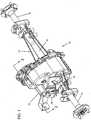
- the transaxle 10 includes a right gear case half 11 operatively connected to a left gear case 12. Also shown in a right axle tube 13 operatively connected to the right gear case half 11 and a left axle tube 14 operatively connected to the left gear case half 12. The axle tubes 13 and 14 are shown as being integral with the gear case halves 11, 12.
- a brake lever 50 which will be described in more detail hereafter, is operatively connected to the transaxle 10.
- the transaxle 10, described thus far, is illustrative of just one transaxle for which the wet brake system of the present invention may be utilized. It is understood that another transaxle or a gear box may be utilized and further the transaxle or gear box may either be a front or a rear.
- the driving force may be either electrical or gas.
- the brake system 20 includes a carrier and ring gear assembly 21, as shown in Figures 6-8 .
- the carrier and ring gear assembly 21 includes a differential carrier 22.
- the differential carrier 22 has a base 23 having a central bore 23a.
- a plurality of openings 23b are formed in the base 23 and are adapted and configured to receive bolts 24.
- Six towers 25 extend to the left, as viewed in Figures 6-8 .
- the towers are generally rectangular and are configured to form a spline for operatively connecting thereto friction plates, as will be described more fully hereafter.
- An output gear 26 having a plurality of teeth 26a has a circular member 26b having a plurality of holes 26c formed therein.
- the bolts 24 pass through the holes 26c and are secured in the openings 23b to secure the output gear 26 to the differential carrier 22.
- a differential carrier shaft 27 is positioned through the bore 23a and first and second pinion gears 28, 29 are mounted on a differential pin 30 which is positioned through a bore 27a in the differential carrier shaft 27.
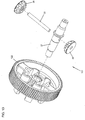
- FIG. 13 Another embodiment of a carrier and ring gear is shown in Figure 13 .
- the integrated carrier and ring gear 121 is similar to the carrier and ring gear assembly 21 except the differential carrier and output gear are combined into an integral one-piece unit 122.
- the carrier and ring gear assembly 121 utilizes similar shaft 27, first pinion gear 28, second pinion gear 29 and differential pin 30. Either carrier and ring gear assembly 21 or 121 may be utilized in the present invention.
- the braking system 20 is a wet type multi-plate braking system that may be either partially or completely submerged in a fluid inside of the transaxle 10.
- the transaxle includes the right gear case half 11 and left gear case 12 operatively connected, by means well known in the art, to form the chamber in which the braking system 20 is either partially or completely submerged.
- a left differential side gear 31 is supported on the left gear case half 12 by bearing 32.
- a right differential side gear 33 is supported in the right gear case half 11 by bearing 34.
- the differential side gears 31, 33 are respectively coupled to axles 16, 17 through an interface of splines 85, 86 or other suitable connections well known in the art.
- the axles, 16 and 17, are positioned in the axle tubes 13, 14.
- the left and right side gears 31, 32 support the rotatable carrier and ring gear assembly 21 or 121 through the shaft 27, which is supported on bearings 95, 96. Through the carrier 21 or 121, the two smaller rotatable differential pinion gears 28, 29 are also supported. The differential pinion gears 28, 29 are at right angles to the two differential side gears 31, 33 with respect to the axles 16, 17.
- the brake system 20 includes multiple stationary friction plates.
- the friction plates include a top stationary friction plate 35, four intermediate stationary friction plates 36 and a bottom stationary friction plate 37.
- Four spacer tubes 38 are pressed into bores 39 that are formed in the left case half 12.
- the intermediate reaction plates 36 have two openings 36a formed in two protrusions 36b.
- the bottom stationary friction plate 37 has two openings 37a formed in protrusions 37b.
- Two of the spacer tubes 38 are utilized to be positioned in the two openings 36a in plates 36.
- the other two spacer rubes 38 are utilized to be positioned in openings 37a of plate 37.
- Three shorter screws 41 go through three additional openings 35b and are seated in three bores 42 also formed in the left case half 12.
- the top stationary friction plate 35 is constrained to the case 12 in all six degrees of motion.
- the stationary plates 36, 37 are allowed translational motion along the axle axis. While the stationary plates 36 and 37 are referred to as "stationary" plates, it is understood that there is a small difference in the inner diameter of openings 36a and 37a and the outer diameter of the tubes 38, thereby allowing a very limited amount of rotational movement.
- the difference or clearance is preferably about 1.524 mm (0.060 inches), although other suitable clearances may also be used.
- the rotary friction plates include five rotary friction plates 43 that are carried by the carrier 22 as will be described more fully hereafter. Another rotary friction plate 44 is slightly larger in width than the rotary friction plates 43. Rotary friction plate 44 is also carried by the carrier 22. A side gear rotary friction plate 45 is carried by the left side differential gear 31, as will be described more fully hereafter.
- the rotary friction plates 43 have six generally rectangular spline interfaces 43a formed on their inner diameter. The spline interfaces 43a are sized and configured to match the shape of the towers 25. The rotary friction plates 43 are positioned on the towers 25 so that the rotary friction plates 43 rotate with the differential carrier 22. Further, translational movement along the axis of the axle is also allowed.
- the rotary friction plate 44 also has six spline interfaces 44a that are similarly sized and configured to match the shape of the towers 25.
- the rotary friction plate 44 therefore rotates with the carrier 22 and translational movement is also allowed along the axis of the axle.
- the tower 25 extends only approximately halfway through the friction plate 44.
- the friction plate 44 is still supported and carried by the tower 25.
- that portion of the friction plate 44 that extends to the left of the tower 25 provides for a contact surface and ensures that the side gear rotary friction plate 45 does not contact the tower 25 as wear occurs.
- the side gear rotary friction plate 45 has a plurality of grooves 45a that form a spline interface with the longitudinal grooves 31 a formed in the left side gear 31.
- the spline interface ties the rotational movement of the rotary friction plate 45 to that of the left side gear 31 while still allowing movement along the longitudinal axis.
- a ball ramp plate 46 is positioned between the bottom stationary friction plate 37 and the left case half 12. Six balls 47 are positioned in pockets 48 formed in the left case half 12. The ball ramp 46 is supported by the balls 47.
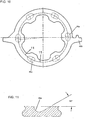
- the ball ramp plate 46 has six cam grooves 46a, best seen in Figures 10 and 11 . The balls 47 are also positioned in the cam grooves 46a, thereby supporting the ball ramp plate 46.
- a brake lever 50 is operatively connected, by means well known in the art, by a brake lever shaft 51. At the end of the shaft 51 is a cam interface 51 a. The cam interface 51 a is positioned to contact the ball ramp plate 46 at extension 46b.
- a suitable cable mechanism (not shown), which is well known in the art, will rotate the brake lever 50, and thereby the shaft 51 so as to cause the cam interface 51a to contact the projection 46b thereby rotating the ball ramp plate 46.
- the interface between the balls 47 and the cam grooves 46a create motion both rotationally about the axle axis and in translational motion along the axle axis, to the right as shown in the figures. This provides the clamping force to the brake system 20.
- This translational or longitudinal motion is used to squeeze the rotary plates 43, 44 and the stationary plates 35, 36 and 37 to create a resistance to rotation of the side differential gear 31 and the carrier 22. This will in turn cause resistance to the rotation of the axles 16, 17.
- the ball ramp has a small rotational movement of approximately 7 degrees, although other suitable amounts may be utilized.
- the brake squeeze occurs between the translational movement of the ball ramp plate 46 and the top stationary friction plate 35 that is constrained to the case half 12 in all six degrees of motion.
- the top stationary friction plate 35 acts as the final stationary friction plate in the brake pack. All of the other stationary friction plates 36, 37 do not allow rotation about the axle axis, but they are allowed translational motion along the axle axis. This is achieved by interfacing the stationary friction plate 36, 37 over spacer tubes 38 positioned and held between the case half 12 and the top stationary friction plate 35.
- the spacer tubes 38 as previously discussed are constrained to the left case half 12.
- the side gear rotary friction plate 45 is supported by the differential side gear 31 and the rotary friction plates 43 and 44 are supported by the differential carrier 22.
- the spline interface on the side gear rotational friction plate 45 constrains relative rotational motion between the left side gear 31 and the rotary friction plate 45, but it does allow translational motion along the axle axis.
- the spline interface with the rotary friction plates 43 and 44 constrain the relative rotational movement between the carrier 22 and the rotary friction plates 43, 44 but does allow for translational motion on the towers along the axle axis.
- Oil seals 97, 98 are provided so as to make a fluid-tight cavity in which the brake system 20 may be submerged or partially submerged in fluid, as is well known in the art
- the brake system 20 of the present invention thereby provides for braking when a vehicle is parked and possibly one of the wheels is able to slip.
- a bias is introduced into the system.
- biasing is reduced or eliminated by varying the alternating arrangement of rotary and stationary friction plates.
- the typical arrangement is to have alternating rotary and friction plates.
- the present invention does so with respect to the rotary friction plates 43 and the stationary friction plates 35 and 36.
- Rotary plates 43 and 44 are tied to the carrier 22 and rotary friction plate 45 is tied to the side gear 31.
- Rotary friction plate 45 directly interacts with the rotary friction plate 44 and helps to synchronize the side gear 31 to the carrier 22 to reduce or eliminate the braking torque bias experienced on the two side gears. While it has been found advantageous to use two rotary friction plates 44, 43 adjacent and tied to the carrier in this arrangement of rotary plates, it is recognized that it is only necessary to have at least one rotary friction plate tied to the carrier. This provides for adjacent and interacting rotary friction plates, with one 43 or 44 tied to the carrier and one 45 tied to the side gear.
- a differential carrier 200 with side gears 201 and 202 Incorporated into and integral to the side gear 202 is a plate 202a that has friction surfaces 202b and 202c. Bearings 203 and 204 support the side gears 201 and 202.
- the plate 202a similar to the plate 45 is operatively connected to the side gear. However in this embodiment it is incorporated integrally into the side gear.
- a carrier rotary friction plate 205 is adjacent the plate 202a, similar to plates 44 and 45 being adjacent to each other in the first embodiment.
- Plates 207 and 208 are dual moveable stationary plates that squeeze the friction plates 202a and 205. The plates 207 and 208 react out to the case and are operatively connected to the case. The plates 207 and 208 provide for the moveable translational movement.
- the differential carrier 300 has friction surfaces 301 and 302 integral with the carrier 300.
- Two rotary side gear friction plates 305a and 305b are positioned proximate the surfaces 301 and 302, although only one is necessary.
- Two moveable stationary friction plates are positioned adjacent the side gear rotary friction plates.
- side gears 306 and 307 are supported by bearings 308 and 309.
- the differential carrier 300 incorporates the rotary side friction plates of the first embodiment either as operatively connected to or an integral portion of the carrier 300. Plates 303 and 304 are operatively connected to the case through a force applying axial member.
- FIG 16 there is schematically shown a differential carrier 400 and two side gears 401 and 402 supported by bearings 403 and 404.
- This embodiment shows the concept of a stationary friction surface being incorporated into a portion of the case.
- the case is represented by member 405 and formed therein is a surface 405a that has a case friction surface 405b.
- a rotary side gear friction plate 406, having friction surfaces 406a and 406b, is operatively connected to the side gear 401 by suitable means such as that described with respect to the first embodiment.
- Adjacent the rotary side gear friction plate is a rotary carrier friction plate 407 suitably mounted on the carrier 400 by suitable means such as that previously described with respect to the other embodiments.
- a moveable stationary friction plate 409 is suitably mounted to react through the case 405 and squeezes the friction plates 406 and 407 against the case 405. Plate 409 is operatively connected to the case through a force applying member.
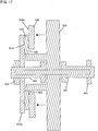
- the embodiment shown in Figure 17 demonstrates the concept of at least two carrier rotary friction surfaces and one limited rotation or stationary friction surface and a rotary side gear friction surface used in a braking application.
- the embodiment includes a differential carrier 500 and side gears 501 and 502 mounted on bearings 503 and 504.
- the bearing 504 accepts thrusts and radial loading.
- the side gear 502 has a plate 502a (having a friction surface 502b) that is a portion of or integral with the side gear 502, similar to that described with respect to Figure 16 .
- a rotary carrier friction plate 505 is suitably mounted to the differential carrier 500 similar to the first embodiment described in Figures 1-13 .
- a force-applying member 508 with a single limited rotation surface 508a is provided and pushes the friction plates 505 and 502a and reacts through the angular thrust-bearing 504 and the case.
- Member 508 is operatively connected to the case through a force applying member.
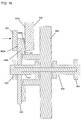
- Figure 18 discloses an embodiment that demonstrates the concept of a single carrier rotary friction surface and a single limited rotation or stationary friction surface and a rotary side gear friction plate used in a braking operation.
- the embodiment shown in Figure 18 includes a differential carrier 600 having first and second side gears 601 and 602 supported by bearings 603 and 604.
- a thrust bearing 605 is capable of supporting radial and thrust loads and is supported through the case.
- the differential carrier 600 includes a single friction surface 600a that interacts (through rotary side gear friction plate 610) with a force-applying member 607 with limited rotation.
- Member 607 is operatively connected to the case through a force applying member.
Landscapes
- Engineering & Computer Science (AREA)
- General Engineering & Computer Science (AREA)
- Mechanical Engineering (AREA)
- Retarders (AREA)
- Braking Arrangements (AREA)
Abstract
Description
- This invention relates generally to a wet brake system and more particularly to a wet brake system wherein a series of plates are operatively connected to the differential carrier, housing and a differential side gear.
- The present invention is applicable to smaller vehicles, either electric or gas, and may be incorporated into either the front or the rear axles. Examples of such vehicles are ATV's, golf, turf and light utility vehicles. Drum brakes on such vehicles have a typical problem in that they wear out and make noise. The semi-metallic shoes and rotors wear from normal use and from being exposed to the elements. Additionally, they have a tendency to squawk as parts wear.
- One example of a wet brake system that has been developed for such vehicles is disclosed in
U.S. Pat. No. 6,293,890 entitled "Brake System for Vehicles" and assigned to Kawasaki. This patent describes a brake system for use in vehicles wherein the brake system is tied to the differential carrier and axle. - One further example of a wet brake system that has been developed is disclosed in
U.S. Patent 4,950,414 entitled "Differential Drive" and assigned to Uni-Cardan AG. This patent describes a differential drive, wherein all rotary friction surfaces are located on one differential gear. Between all rotary friction surfaces a stationary friction surface is located, which can be brought into contact with the rotary friction surfaces to cause braking. - The present invention ties the brake system to the differential and a side gear and not to the axle. Still further, the present invention addresses the problems of bias and provides for a brake system which helps to eliminate bias between the two wheels driven by the differential.
- In one embodiment, the invention is a brake system for use in a vehicle. The brake system includes a differential carrier and an output gear operatively connected thereto. A case defines a cavity for housing the differential carrier. At least one carrier rotary friction surface is operatively connected to the differential carrier. A differential mechanism has first and second differential side gears. At least one side gear rotary friction surface is operatively connected to one of the first and second differential side gears. At least one limited rotation friction surface is operatively connected to the case whereby during a braking operation the at least one carrier rotary friction surface and the at least one side gear rotary friction surface are pressed together causing braking of the differential carrier and the first and second differential side gears. The carrier is supported by the first and second differential side gears. In a preferred embodiment, the invention further comprises the at least one carrier rotary friction surface and the at least one side gear rotary friction surface are positioned adjacent to each other and have direct contact during a braking event, whereby braking torque biasing is reduced.
- In another embodiment, the invention is a brake system for use in a vehicle. The brake system includes a differential carrier and an output gear operatively connected thereto. A case defines a cavity for housing the differential carrier. At least one carrier rotary friction plate is operatively connected to the differential carrier. A differential mechanism has first and second differential side gears. At least one side gear rotary friction plate is operatively connected to one of the first and second differential side gears. At least one limited rotation friction plate is operatively connected to the case whereby during a braking operation the at least one carrier rotary friction plate and the at least one side gear rotary friction plate are pressed together causing braking of the differential carrier and the first and second differential side gears. The carrier is supported by the first and second differential side gears.
-
-
Figure 1 is a perspective view of a drive train according to the present invention; -
Figure 2 is a cross-sectional view taken generally along the lines 2-2 ofFigure 1 ; -
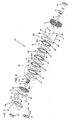
Figure 3 is an exploded perspective of a portion of the invention shown inFigure 2 ; -
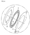
Figure 4 is an enlarged view of a portion of the invention circled inFigure 3 ; -
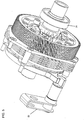
Figure 5 is an assembled perspective view of the components ofFigure 3 ; -
Figure 6 is an exploded perspective view of the carrier and ring gear portion of the invention shown inFigure 3 ; -
Figure 7 is an assembled view of the carrier and ring gear shown inFigure 6 ; -
Figure 8 is an exploded perspective view of the carrier and ring gear shown inFigure 6 , viewed from the left; -
Figure 9 is an exploded perspective view, similar to that shown inFigure 3 , however, shown from the left; -
Figure 10 is a flat plan view of the ball ramp plate shown inFigure 3 ; -
Figure 11 is an enlarged sectional view of a portion of the ball ramp shown inFigure 10 , taken generally along the lines 11-11; -
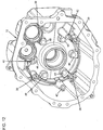
Figure 12 is a perspective view showing the interior of a portion of the case shown inFigure 1 ; -
Figure 13 is an exploded perspective view of another embodiment showing an integrated ring gear and carrier; -
Figure 14 is a schematic representation of another embodiment of the present invention; -
Figure 15 is a schematic of another embodiment of the present invention; -
Figure 16 is a schematic of another embodiment of the present invention; -
Figure 17 is a schematic of another embodiment of the present invention; and -
Figure 18 is a schematic of another embodiment of the present invention. - Referring to the drawings, wherein like numerals represent like parts throughout the several views, there is generally disclosed at 10 a transaxle. The
transaxle 10 includes a rightgear case half 11 operatively connected to aleft gear case 12. Also shown in aright axle tube 13 operatively connected to the rightgear case half 11 and aleft axle tube 14 operatively connected to the leftgear case half 12. Theaxle tubes gear case halves brake lever 50, which will be described in more detail hereafter, is operatively connected to thetransaxle 10. Thetransaxle 10, described thus far, is illustrative of just one transaxle for which the wet brake system of the present invention may be utilized. It is understood that another transaxle or a gear box may be utilized and further the transaxle or gear box may either be a front or a rear. In addition, the driving force may be either electrical or gas. - Referring now to
Figures 3 and9 , there are shown exploded perspective views of thebrake system 20 of the present invention. Thebrake system 20 includes a carrier andring gear assembly 21, as shown inFigures 6-8 . The carrier andring gear assembly 21 includes adifferential carrier 22. Thedifferential carrier 22 has a base 23 having acentral bore 23a. A plurality ofopenings 23b are formed in thebase 23 and are adapted and configured to receivebolts 24. Sixtowers 25 extend to the left, as viewed inFigures 6-8 . The towers are generally rectangular and are configured to form a spline for operatively connecting thereto friction plates, as will be described more fully hereafter. Anoutput gear 26 having a plurality ofteeth 26a has acircular member 26b having a plurality ofholes 26c formed therein. Thebolts 24 pass through theholes 26c and are secured in theopenings 23b to secure theoutput gear 26 to thedifferential carrier 22. As is well known in the art, adifferential carrier shaft 27 is positioned through thebore 23a and first and second pinion gears 28, 29 are mounted on adifferential pin 30 which is positioned through abore 27a in thedifferential carrier shaft 27. - Another embodiment of a carrier and ring gear is shown in
Figure 13 . The integrated carrier andring gear 121 is similar to the carrier andring gear assembly 21 except the differential carrier and output gear are combined into an integral one-piece unit 122. The carrier andring gear assembly 121 utilizessimilar shaft 27,first pinion gear 28,second pinion gear 29 anddifferential pin 30. Either carrier andring gear assembly - The
braking system 20 is a wet type multi-plate braking system that may be either partially or completely submerged in a fluid inside of thetransaxle 10. Referring now, especially toFigures 2 ,3 and9 , the transaxle includes the rightgear case half 11 and leftgear case 12 operatively connected, by means well known in the art, to form the chamber in which thebraking system 20 is either partially or completely submerged. A leftdifferential side gear 31 is supported on the leftgear case half 12 by bearing 32. A rightdifferential side gear 33 is supported in the rightgear case half 11 by bearing 34. The differential side gears 31, 33 are respectively coupled toaxles splines axle tubes - The left and right side gears 31, 32 support the rotatable carrier and
ring gear assembly shaft 27, which is supported onbearings carrier axles brake system 20 includes multiple stationary friction plates. The friction plates include a topstationary friction plate 35, four intermediatestationary friction plates 36 and a bottomstationary friction plate 37. Fourspacer tubes 38 are pressed intobores 39 that are formed in theleft case half 12. Four longer screws 40 go through fouropenings 35a formed in thetop friction plate 35 and go through thespacer tubes 38 and are secured into thebores 39 of theleft casing half 12. Theintermediate reaction plates 36 have twoopenings 36a formed in twoprotrusions 36b. Similarly, the bottomstationary friction plate 37 has twoopenings 37a formed inprotrusions 37b. Two of thespacer tubes 38 are utilized to be positioned in the twoopenings 36a inplates 36. The other twospacer rubes 38 are utilized to be positioned inopenings 37a ofplate 37. Threeshorter screws 41 go through threeadditional openings 35b and are seated in threebores 42 also formed in theleft case half 12. The topstationary friction plate 35 is constrained to thecase 12 in all six degrees of motion. However, thestationary plates stationary plates openings tubes 38, thereby allowing a very limited amount of rotational movement. The difference or clearance is preferably about 1.524 mm (0.060 inches), although other suitable clearances may also be used. - A plurality of rotary friction plates are utilized. The rotary friction plates include five
rotary friction plates 43 that are carried by thecarrier 22 as will be described more fully hereafter. Anotherrotary friction plate 44 is slightly larger in width than therotary friction plates 43.Rotary friction plate 44 is also carried by thecarrier 22. A side gearrotary friction plate 45 is carried by the left sidedifferential gear 31, as will be described more fully hereafter. Therotary friction plates 43 have six generallyrectangular spline interfaces 43a formed on their inner diameter. The spline interfaces 43a are sized and configured to match the shape of thetowers 25. Therotary friction plates 43 are positioned on thetowers 25 so that therotary friction plates 43 rotate with thedifferential carrier 22. Further, translational movement along the axis of the axle is also allowed. Therotary friction plate 44 also has sixspline interfaces 44a that are similarly sized and configured to match the shape of thetowers 25. Therotary friction plate 44 therefore rotates with thecarrier 22 and translational movement is also allowed along the axis of the axle. In viewingFigure 2 , it can be seen that thetower 25 extends only approximately halfway through thefriction plate 44. Thefriction plate 44 is still supported and carried by thetower 25. However, that portion of thefriction plate 44 that extends to the left of thetower 25 provides for a contact surface and ensures that the side gearrotary friction plate 45 does not contact thetower 25 as wear occurs. The side gearrotary friction plate 45 has a plurality ofgrooves 45a that form a spline interface with thelongitudinal grooves 31 a formed in theleft side gear 31. The spline interface ties the rotational movement of therotary friction plate 45 to that of theleft side gear 31 while still allowing movement along the longitudinal axis. - A
ball ramp plate 46 is positioned between the bottomstationary friction plate 37 and theleft case half 12. Sixballs 47 are positioned inpockets 48 formed in theleft case half 12. Theball ramp 46 is supported by theballs 47. Theball ramp plate 46 has sixcam grooves 46a, best seen inFigures 10 and 11 . Theballs 47 are also positioned in thecam grooves 46a, thereby supporting theball ramp plate 46. Abrake lever 50 is operatively connected, by means well known in the art, by abrake lever shaft 51. At the end of theshaft 51 is a cam interface 51 a. The cam interface 51 a is positioned to contact theball ramp plate 46 atextension 46b. Therefore, when the brake is activated, a suitable cable mechanism (not shown), which is well known in the art, will rotate thebrake lever 50, and thereby theshaft 51 so as to cause the cam interface 51a to contact theprojection 46b thereby rotating theball ramp plate 46. When theball ramp plate 46 is rotated through thebrake lever 50, the interface between theballs 47 and thecam grooves 46a create motion both rotationally about the axle axis and in translational motion along the axle axis, to the right as shown in the figures. This provides the clamping force to thebrake system 20. This translational or longitudinal motion is used to squeeze therotary plates stationary plates side differential gear 31 and thecarrier 22. This will in turn cause resistance to the rotation of theaxles - The brake squeeze occurs between the translational movement of the
ball ramp plate 46 and the topstationary friction plate 35 that is constrained to thecase half 12 in all six degrees of motion. The topstationary friction plate 35 acts as the final stationary friction plate in the brake pack. All of the otherstationary friction plates stationary friction plate spacer tubes 38 positioned and held between thecase half 12 and the topstationary friction plate 35. Thespacer tubes 38, as previously discussed are constrained to theleft case half 12. As previously discussed, the side gearrotary friction plate 45 is supported by thedifferential side gear 31 and therotary friction plates differential carrier 22. The spline interface on the side gearrotational friction plate 45 constrains relative rotational motion between theleft side gear 31 and therotary friction plate 45, but it does allow translational motion along the axle axis. The spline interface with therotary friction plates carrier 22 and therotary friction plates brake system 20 may be submerged or partially submerged in fluid, as is well known in the art - The
brake system 20 of the present invention, thereby provides for braking when a vehicle is parked and possibly one of the wheels is able to slip. However, in the prior art, by alternating the stationary and rotary friction plates, a bias is introduced into the system. However, in the present invention, biasing is reduced or eliminated by varying the alternating arrangement of rotary and stationary friction plates. The typical arrangement is to have alternating rotary and friction plates. The present invention does so with respect to therotary friction plates 43 and thestationary friction plates rotary friction plates Rotary plates carrier 22 androtary friction plate 45 is tied to theside gear 31.Rotary friction plate 45 directly interacts with therotary friction plate 44 and helps to synchronize theside gear 31 to thecarrier 22 to reduce or eliminate the braking torque bias experienced on the two side gears. While it has been found advantageous to use tworotary friction plates - It is understood that the foregoing has described the
brake system 20 as being operatively connected to theleft side gear 31. It is understood that thebrake system 20 could also be operatively connected to theright side gear 33. - In this application, while in the prior art the
plates - The plates, 35-37, 43-45, all have two surfaces. It is clear from the foregoing description and the drawings the interaction of the two surfaces of each plate and their interaction with their adjacent plates. However, it is also understood that there are embodiments wherein a differential side gear, differential carrier or case may be utilized as either a rotary friction surface or a stationary friction surface as explained in the following.
Figures 14-18 are schematic representations of such embodiments. - In
Figure 14 , this embodiment demonstrates the use of a rotary friction surface as being part of the differential side gear. For all ofFigures 14-18 , the specific configurations and attachments of the parts are not necessary as one skilled in the art readily will appreciate the relationships, in light of the detailed discussion with respect toFigures 1-13 . As inFigures 1-13 , the embodiments shown inFigure 14-18 , all have the differential carrier supported by the side gears. - Referring now to
Figure 14 , there is shown adifferential carrier 200 with side gears 201 and 202. Incorporated into and integral to theside gear 202 is aplate 202a that has friction surfaces 202b and 202c.Bearings plate 202a, similar to theplate 45 is operatively connected to the side gear. However in this embodiment it is incorporated integrally into the side gear. A carrierrotary friction plate 205 is adjacent theplate 202a, similar toplates Plates friction plates plates plates - Referring now to
Figure 15 , there is demonstrated the concept of a rotary friction surface being a portion of the differential carrier. Thedifferential carrier 300 has friction surfaces 301 and 302 integral with thecarrier 300. Two rotary sidegear friction plates surfaces bearings Figure 15 , thedifferential carrier 300 incorporates the rotary side friction plates of the first embodiment either as operatively connected to or an integral portion of thecarrier 300.Plates - In
Figure 16 , there is schematically shown adifferential carrier 400 and two side gears 401 and 402 supported bybearings member 405 and formed therein is asurface 405a that has acase friction surface 405b. A rotary sidegear friction plate 406, havingfriction surfaces side gear 401 by suitable means such as that described with respect to the first embodiment. Adjacent the rotary side gear friction plate is a rotarycarrier friction plate 407 suitably mounted on thecarrier 400 by suitable means such as that previously described with respect to the other embodiments. A moveablestationary friction plate 409 is suitably mounted to react through thecase 405 and squeezes thefriction plates case 405.Plate 409 is operatively connected to the case through a force applying member. - The embodiment shown in
Figure 17 demonstrates the concept of at least two carrier rotary friction surfaces and one limited rotation or stationary friction surface and a rotary side gear friction surface used in a braking application. The embodiment includes adifferential carrier 500 and side gears 501 and 502 mounted onbearings bearing 504 accepts thrusts and radial loading. Theside gear 502 has aplate 502a (having afriction surface 502b) that is a portion of or integral with theside gear 502, similar to that described with respect toFigure 16 . A rotarycarrier friction plate 505 is suitably mounted to thedifferential carrier 500 similar to the first embodiment described inFigures 1-13 . Finally, a force-applyingmember 508 with a singlelimited rotation surface 508a is provided and pushes thefriction plates Member 508 is operatively connected to the case through a force applying member. -
Figure 18 discloses an embodiment that demonstrates the concept of a single carrier rotary friction surface and a single limited rotation or stationary friction surface and a rotary side gear friction plate used in a braking operation. The embodiment shown inFigure 18 includes adifferential carrier 600 having first and second side gears 601 and 602 supported bybearings thrust bearing 605 is capable of supporting radial and thrust loads and is supported through the case. Thedifferential carrier 600 includes asingle friction surface 600a that interacts (through rotary side gear friction plate 610) with a force-applyingmember 607 with limited rotation.Member 607 is operatively connected to the case through a force applying member.
Claims (9)
- A brake system for use in a vehicle having an axle (16, 17), the brake system (20) comprising:a differential carrier (22, 121) and an output gear (26) operatively connected thereto;a case (11, 12) defining the cavity for housing the differential carrier (22, 121);alternating stationary and rotary friction surfaces,at least one of the rotary friction surfaces (43, 44) being rotationally tied to the differential carrier (22, 121);a differential mechanism having first and second differential side gears (31, 33);at least one of the rotary friction surfaces (45) being rotationally tied to one of the first and second differential side gears (31, 33);the stationary friction surfaces (35, 36, 37) being constrained to the case (11,12),wherein the differential carrier (22, 121) is supported by the first and second differential side gears (31, 33),wherein the at least one rotary friction surface (43, 44) rotationally tied to the differential carrier (22, 121) and the at least one rotary friction surface (45) rotationally tied to one of the side gears are positioned adjacent to each other and have direct contact during a braking operation, for synchronizing the one of the first and second differential side gears to the differential carrier to reduce or eliminate the braking torque bias, and during the braking operation the at least one rotary friction surface (43, 44) rotationally tied to the differential carrier (22, 121), the at least one rotary friction surface (45) rotationally tied to the at least one side gear (31, 33), and the at least one stationary friction surface (35, 36, 37) constrained to the case (11, 12) are squeezed together by a translational or longitudinal motion along the axis of the axle (16, 17) causing braking of the differential carrier (22, 121) and the first and second differential side gears (31, 33), for causing resistance to the rotation of the axle (16, 17), so as to brake the vehicle.
- The brake system of claim 1, wherein at least one of the rotary friction surfaces (301, 302; 600a) rotationally tied to the differential carrier (300; 600) is a portion of the differential carrier (300; 600).
- The brake system of claim 1, wherein at least one of the rotary friction surfaces (202b, 202c; 502b) rotationally tied to the side gear (202; 502) is a portion of the side gear (202; 502).
- The brake system of claim 1, wherein one of the stationary friction surfaces (405b) is a portion of the case (405).
- The brake system of claim 1, wherein at least one of the rotary friction surfaces rotationally tied to the carrier is a surface of at least one rotary friction plate (43, 44) rotationally tied to the carrier, at least one of the rotary friction surfaces rotationally tied to the side gear is a surface of at least one rotary friction plate (45) rotationally tied to the side gear, and at least one of the stationary friction surfaces is a surface of at least one stationary friction plate (35, 36, 37) constrained to the case.
- The brake system of claim 1, wherein the differential carrier (22, 121) and the output gear (26) are integral.
- The brake system of claim 5, wherein the at least one stationary friction plate (35) is constrained to the case in all 6 degrees of motion.
- The brake system of claim 5 in wherein the additional stationary friction plates (36, 37) have a limited amount of rotary movement.
- The brake system of claim 8, further comprising:a) a plurality of pockets formed in the cavity of the case;b) a ball ramp plate (46) positioned proximate the pockets, the ball ramp plate having a plurality of cam grooves (46a);c) a plurality of balls (47) positioned in the pockets and cam grooves; andd) a brake lever (50) operatively connected to the ball ramp plate, wherein the brake lever causes rotational movement of the ball ramp and movement of the balls in the cam grooves results in translational movement of the ball ramp plate thereby squeezing together the rotary friction plates and the stationary friction plates.
Applications Claiming Priority (2)
| Application Number | Priority Date | Filing Date | Title |
|---|---|---|---|
| US11/057,399 US7367913B2 (en) | 2005-02-11 | 2005-02-11 | Wet brake system for vehicles |
| PCT/US2005/006751 WO2006088469A1 (en) | 2005-02-11 | 2005-03-02 | Wet brake system for vehicles |
Publications (3)
| Publication Number | Publication Date |
|---|---|
| EP1851465A1 EP1851465A1 (en) | 2007-11-07 |
| EP1851465A4 EP1851465A4 (en) | 2008-03-12 |
| EP1851465B1 true EP1851465B1 (en) | 2012-05-09 |
Family
ID=36816352
Family Applications (1)
| Application Number | Title | Priority Date | Filing Date |
|---|---|---|---|
| EP05724321A Ceased EP1851465B1 (en) | 2005-02-11 | 2005-03-02 | Wet brake system for vehicles |
Country Status (4)
| Country | Link |
|---|---|
| US (1) | US7367913B2 (en) |
| EP (1) | EP1851465B1 (en) |
| CA (1) | CA2597491C (en) |
| WO (1) | WO2006088469A1 (en) |
Families Citing this family (3)
| Publication number | Priority date | Publication date | Assignee | Title |
|---|---|---|---|---|
| US8246010B2 (en) | 2009-08-13 | 2012-08-21 | Hess Daniel L | Fluid shear actuated hoist brake |
| DE102011103249B4 (en) | 2011-06-03 | 2021-10-07 | Volkswagen Aktiengesellschaft | Differential arrangement, in particular crown gear differential with a self-locking multi-plate clutch |
| DE102019208178B3 (en) * | 2019-06-05 | 2020-07-23 | Continental Teves Ag & Co. Ohg | Multi-disc brake for a motor vehicle |
Family Cites Families (23)
| Publication number | Priority date | Publication date | Assignee | Title |
|---|---|---|---|---|
| US1950214A (en) * | 1929-04-06 | 1934-03-06 | Gen Electric | Method of soldering metal objects |
| US1847828A (en) | 1930-07-17 | 1932-03-01 | Fred A Gerling | Automobile brake |
| US2424942A (en) | 1942-11-26 | 1947-07-29 | Der Eisenund Stahlwerke Vormal | Self-locking equalizing drive |
| US4559846A (en) | 1983-11-10 | 1985-12-24 | Dana Corporation | System for shifting a vehicle to two or four-wheel drive |
| US4715467A (en) | 1984-03-27 | 1987-12-29 | Fuji Jukogyo Kabushiki Kaisha | Control system for a four-wheel drive vehicle |
| JPH0525946Y2 (en) | 1987-01-13 | 1993-06-30 | ||
| HU201832B (en) | 1987-03-26 | 1990-12-28 | Magyar Vagon Es Gepgyar | Running gear of adjustable wheel track having equalizing gear and epicyclic gear drive |
| EP0326975B1 (en) | 1988-02-05 | 1991-07-31 | Mineralölwerke Wenzel und Weidmann Zweigniederlassung der Fuchs Mineralölwerke GmbH, Mannheim | Lubricant for traction drive with continuously variable transmission |
| DE3909112A1 (en) * | 1988-05-05 | 1990-09-27 | Uni Cardan Ag | GEARBOX |
| DE3920861A1 (en) | 1989-06-07 | 1990-12-13 | Gkn Automotive Ag | GEARBOX |
| US5007886A (en) | 1989-12-26 | 1991-04-16 | Eaton Corporation | Limited slip differential |
| US5195604A (en) | 1991-06-17 | 1993-03-23 | Warn Industries, Inc. | All wheel drive vehicle with independent wheel braking |
| US5190123A (en) | 1991-07-01 | 1993-03-02 | Cannon Engineering Technologies, Inc. | Direct drive axle brake and cooling system |
| US5330394A (en) | 1991-07-09 | 1994-07-19 | Hydro-Gear Limited Partnership | Rider transaxle having improved hydrostatic transmission |
| US5484347A (en) | 1993-03-10 | 1996-01-16 | Eaton Corporation | Variable rate locking differential with pyrolitic-carbon friction clutch |
| US5366040A (en) | 1993-10-19 | 1994-11-22 | Kanzaki Kokyukoki Mfg. Co., Ltd. | Braking device for a working vehicle |
| US5804935A (en) | 1997-02-06 | 1998-09-08 | Radev; Vladimir | Drive system for electric vehicles |
| US6146304A (en) * | 1998-12-22 | 2000-11-14 | Caterpillar Inc. | Vehicle differential |
| JP3192639B2 (en) | 1999-04-08 | 2001-07-30 | 川崎重工業株式会社 | Vehicle braking system |
| US6354421B1 (en) | 1999-12-28 | 2002-03-12 | Shin Nippon Wheel Industries Co., Ltd. | Brake system in buggy |
| JP4274508B2 (en) | 2000-03-15 | 2009-06-10 | 本田技研工業株式会社 | Two-wheel four-wheel drive switching device for vehicles |
| US6345712B1 (en) | 2000-06-09 | 2002-02-12 | Dana Corporation | Axle assembly with liquid cooled brake |
| US6866605B2 (en) | 2002-06-28 | 2005-03-15 | Caterpillar Inc | Power train assembly |
-
2005
- 2005-02-11 US US11/057,399 patent/US7367913B2/en not_active Expired - Lifetime
- 2005-03-02 WO PCT/US2005/006751 patent/WO2006088469A1/en not_active Ceased
- 2005-03-02 EP EP05724321A patent/EP1851465B1/en not_active Ceased
- 2005-03-02 CA CA2597491A patent/CA2597491C/en not_active Expired - Lifetime
Also Published As
| Publication number | Publication date |
|---|---|
| US20060183591A1 (en) | 2006-08-17 |
| EP1851465A1 (en) | 2007-11-07 |
| WO2006088469A1 (en) | 2006-08-24 |
| CA2597491C (en) | 2010-02-09 |
| CA2597491A1 (en) | 2006-08-24 |
| EP1851465A4 (en) | 2008-03-12 |
| US7367913B2 (en) | 2008-05-06 |
Similar Documents
| Publication | Publication Date | Title |
|---|---|---|
| US12280753B2 (en) | Motor gear unit for disc brake apparatus and disc brake apparatus | |
| CN107917175A (en) | Differential limiting device for vehicle | |
| US9003902B1 (en) | Drive assembly | |
| US20080173515A1 (en) | Disk spring hydraulic release brake | |
| CN104583585A (en) | Combined motor and brake with rotating brake-release piston | |
| JP4558126B2 (en) | Parallel shaft gear differential with a pinion fitted with a brake shoe | |
| US6837821B2 (en) | Differential | |
| KR101370233B1 (en) | Rotary fluid pressure device and improved parking lock assembly therefor | |
| CN113858878A (en) | Wheel hub assembly, drive axle assembly and vehicle | |
| US7481735B2 (en) | Transmission having integrated braking device | |
| EP2835556B1 (en) | Friction brake device | |
| US6293890B1 (en) | Brake system for vehicles | |
| CA2597491C (en) | Wet brake system for vehicles | |
| KR100281448B1 (en) | Differential gear drive | |
| EP2835554B1 (en) | Friction brake device | |
| EP1038715A2 (en) | Freeing mechanism for motorized gear reducer | |
| EP1132270B1 (en) | Wheel hub for vehicles | |
| JP2894428B2 (en) | Clutch structure | |
| JP3405946B2 (en) | Coupling | |
| JP2008527258A (en) | Electric parking brake | |
| US6536560B1 (en) | Single braking assembly for a drive axle | |
| EP1110790A1 (en) | A reduction gear unit with built-in brake for industrial vehicles | |
| CN113858938A (en) | Wheel hub assembly, drive axle assembly and vehicle | |
| JP3214464B2 (en) | Clutch structure | |
| JP2006097821A (en) | Electric disc brake |
Legal Events
| Date | Code | Title | Description |
|---|---|---|---|
| PUAI | Public reference made under article 153(3) epc to a published international application that has entered the european phase |
Free format text: ORIGINAL CODE: 0009012 |
|
| 17P | Request for examination filed |
Effective date: 20070911 |
|
| AK | Designated contracting states |
Kind code of ref document: A1 Designated state(s): DE FR GB IT |
|
| A4 | Supplementary search report drawn up and despatched |
Effective date: 20080212 |
|
| DAX | Request for extension of the european patent (deleted) | ||
| RBV | Designated contracting states (corrected) |
Designated state(s): DE FR GB IT |
|
| 17Q | First examination report despatched |
Effective date: 20080725 |
|
| GRAP | Despatch of communication of intention to grant a patent |
Free format text: ORIGINAL CODE: EPIDOSNIGR1 |
|
| GRAS | Grant fee paid |
Free format text: ORIGINAL CODE: EPIDOSNIGR3 |
|
| GRAA | (expected) grant |
Free format text: ORIGINAL CODE: 0009210 |
|
| AK | Designated contracting states |
Kind code of ref document: B1 Designated state(s): DE FR GB IT |
|
| REG | Reference to a national code |
Ref country code: GB Ref legal event code: FG4D |
|
| REG | Reference to a national code |
Ref country code: DE Ref legal event code: R082 Ref document number: 602005034123 Country of ref document: DE Representative=s name: EISENFUEHR, SPEISER & PARTNER, DE Ref country code: DE Ref legal event code: R082 Ref document number: 602005034123 Country of ref document: DE Representative=s name: EISENFUEHR SPEISER PATENTANWAELTE RECHTSANWAEL, DE |
|
| REG | Reference to a national code |
Ref country code: DE Ref legal event code: R096 Ref document number: 602005034123 Country of ref document: DE Effective date: 20120705 |
|
| PLBE | No opposition filed within time limit |
Free format text: ORIGINAL CODE: 0009261 |
|
| STAA | Information on the status of an ep patent application or granted ep patent |
Free format text: STATUS: NO OPPOSITION FILED WITHIN TIME LIMIT |
|
| 26N | No opposition filed |
Effective date: 20130212 |
|
| REG | Reference to a national code |
Ref country code: DE Ref legal event code: R097 Ref document number: 602005034123 Country of ref document: DE Effective date: 20130212 |
|
| REG | Reference to a national code |
Ref country code: FR Ref legal event code: PLFP Year of fee payment: 12 |
|
| REG | Reference to a national code |
Ref country code: FR Ref legal event code: PLFP Year of fee payment: 13 |
|
| REG | Reference to a national code |
Ref country code: FR Ref legal event code: PLFP Year of fee payment: 14 |
|
| PGFP | Annual fee paid to national office [announced via postgrant information from national office to epo] |
Ref country code: GB Payment date: 20220324 Year of fee payment: 18 |
|
| PGFP | Annual fee paid to national office [announced via postgrant information from national office to epo] |
Ref country code: FR Payment date: 20220322 Year of fee payment: 18 |
|
| PGFP | Annual fee paid to national office [announced via postgrant information from national office to epo] |
Ref country code: IT Payment date: 20220331 Year of fee payment: 18 Ref country code: DE Payment date: 20220406 Year of fee payment: 18 |
|
| P01 | Opt-out of the competence of the unified patent court (upc) registered |
Effective date: 20230517 |
|
| REG | Reference to a national code |
Ref country code: DE Ref legal event code: R119 Ref document number: 602005034123 Country of ref document: DE |
|
| GBPC | Gb: european patent ceased through non-payment of renewal fee |
Effective date: 20230302 |
|
| PG25 | Lapsed in a contracting state [announced via postgrant information from national office to epo] |
Ref country code: GB Free format text: LAPSE BECAUSE OF NON-PAYMENT OF DUE FEES Effective date: 20230302 |
|
| PG25 | Lapsed in a contracting state [announced via postgrant information from national office to epo] |
Ref country code: GB Free format text: LAPSE BECAUSE OF NON-PAYMENT OF DUE FEES Effective date: 20230302 Ref country code: FR Free format text: LAPSE BECAUSE OF NON-PAYMENT OF DUE FEES Effective date: 20230331 Ref country code: DE Free format text: LAPSE BECAUSE OF NON-PAYMENT OF DUE FEES Effective date: 20231003 |
|
| PG25 | Lapsed in a contracting state [announced via postgrant information from national office to epo] |
Ref country code: IT Free format text: LAPSE BECAUSE OF NON-PAYMENT OF DUE FEES Effective date: 20230302 |