EP1850761B1 - Drive shaft for a surgical instrument - Google Patents
Drive shaft for a surgical instrument Download PDFInfo
- Publication number
- EP1850761B1 EP1850761B1 EP06709840.0A EP06709840A EP1850761B1 EP 1850761 B1 EP1850761 B1 EP 1850761B1 EP 06709840 A EP06709840 A EP 06709840A EP 1850761 B1 EP1850761 B1 EP 1850761B1
- Authority
- EP
- European Patent Office
- Prior art keywords
- drive
- attachment according
- attachment
- reamer
- hub
- Prior art date
- Legal status (The legal status is an assumption and is not a legal conclusion. Google has not performed a legal analysis and makes no representation as to the accuracy of the status listed.)
- Active
Links
- 210000000988 bone and bone Anatomy 0.000 claims description 11
- 239000004411 aluminium Substances 0.000 claims description 3
- 229910052782 aluminium Inorganic materials 0.000 claims description 3
- XAGFODPZIPBFFR-UHFFFAOYSA-N aluminium Chemical compound [Al] XAGFODPZIPBFFR-UHFFFAOYSA-N 0.000 claims description 3
- 238000000034 method Methods 0.000 description 8
- 230000007246 mechanism Effects 0.000 description 6
- 230000009467 reduction Effects 0.000 description 6
- 230000005540 biological transmission Effects 0.000 description 4
- 210000000588 acetabulum Anatomy 0.000 description 3
- 230000001154 acute effect Effects 0.000 description 3
- 230000008901 benefit Effects 0.000 description 3
- 210000001624 hip Anatomy 0.000 description 3
- 239000000463 material Substances 0.000 description 3
- 238000001356 surgical procedure Methods 0.000 description 3
- 229910000838 Al alloy Inorganic materials 0.000 description 2
- 241000282472 Canis lupus familiaris Species 0.000 description 2
- 230000009471 action Effects 0.000 description 2
- 229910045601 alloy Inorganic materials 0.000 description 2
- 239000000956 alloy Substances 0.000 description 2
- 210000003484 anatomy Anatomy 0.000 description 2
- 238000013461 design Methods 0.000 description 2
- 230000000694 effects Effects 0.000 description 2
- 238000003754 machining Methods 0.000 description 2
- 230000014759 maintenance of location Effects 0.000 description 2
- 229910052751 metal Inorganic materials 0.000 description 2
- 239000002184 metal Substances 0.000 description 2
- 230000000717 retained effect Effects 0.000 description 2
- 239000010935 stainless steel Substances 0.000 description 2
- 229910001220 stainless steel Inorganic materials 0.000 description 2
- 238000011541 total hip replacement Methods 0.000 description 2
- 229910000831 Steel Inorganic materials 0.000 description 1
- RTAQQCXQSZGOHL-UHFFFAOYSA-N Titanium Chemical compound [Ti] RTAQQCXQSZGOHL-UHFFFAOYSA-N 0.000 description 1
- 238000013459 approach Methods 0.000 description 1
- 230000000712 assembly Effects 0.000 description 1
- 238000000429 assembly Methods 0.000 description 1
- 238000006243 chemical reaction Methods 0.000 description 1
- 230000008878 coupling Effects 0.000 description 1
- 238000010168 coupling process Methods 0.000 description 1
- 238000005859 coupling reaction Methods 0.000 description 1
- 230000000881 depressing effect Effects 0.000 description 1
- 238000003780 insertion Methods 0.000 description 1
- 230000037431 insertion Effects 0.000 description 1
- 239000007788 liquid Substances 0.000 description 1
- 230000013011 mating Effects 0.000 description 1
- 150000002739 metals Chemical class 0.000 description 1
- 125000006850 spacer group Chemical group 0.000 description 1
- 239000010959 steel Substances 0.000 description 1
- 239000010936 titanium Substances 0.000 description 1
- 229910052719 titanium Inorganic materials 0.000 description 1
- XLYOFNOQVPJJNP-UHFFFAOYSA-N water Substances O XLYOFNOQVPJJNP-UHFFFAOYSA-N 0.000 description 1
Images

Classifications
-
- A—HUMAN NECESSITIES
- A61—MEDICAL OR VETERINARY SCIENCE; HYGIENE
- A61B—DIAGNOSIS; SURGERY; IDENTIFICATION
- A61B17/00—Surgical instruments, devices or methods
- A61B17/16—Instruments for performing osteoclasis; Drills or chisels for bones; Trepans
- A61B17/1613—Component parts
- A61B17/1622—Drill handpieces
- A61B17/1624—Drive mechanisms therefor
-
- A—HUMAN NECESSITIES
- A61—MEDICAL OR VETERINARY SCIENCE; HYGIENE
- A61B—DIAGNOSIS; SURGERY; IDENTIFICATION
- A61B17/00—Surgical instruments, devices or methods
- A61B17/16—Instruments for performing osteoclasis; Drills or chisels for bones; Trepans
- A61B17/1613—Component parts
- A61B17/1631—Special drive shafts, e.g. flexible shafts
-
- A—HUMAN NECESSITIES
- A61—MEDICAL OR VETERINARY SCIENCE; HYGIENE
- A61B—DIAGNOSIS; SURGERY; IDENTIFICATION
- A61B17/00—Surgical instruments, devices or methods
- A61B17/16—Instruments for performing osteoclasis; Drills or chisels for bones; Trepans
- A61B17/1662—Instruments for performing osteoclasis; Drills or chisels for bones; Trepans for particular parts of the body
- A61B17/1664—Instruments for performing osteoclasis; Drills or chisels for bones; Trepans for particular parts of the body for the hip
- A61B17/1666—Instruments for performing osteoclasis; Drills or chisels for bones; Trepans for particular parts of the body for the hip for the acetabulum
-
- A—HUMAN NECESSITIES
- A61—MEDICAL OR VETERINARY SCIENCE; HYGIENE
- A61B—DIAGNOSIS; SURGERY; IDENTIFICATION
- A61B17/00—Surgical instruments, devices or methods
- A61B2017/00681—Aspects not otherwise provided for
- A61B2017/00738—Aspects not otherwise provided for part of the tool being offset with respect to a main axis, e.g. for better view for the surgeon
Definitions
- the present invention relates to an attachment for a surgical instrument, particularly a cutting device such as a reamer.
- In-line acetabular reamer attachments are known in which the attachment consists of a straight tubular body with a drive input at one end and a drive output at the other end.
- the drive input and output are coupled by a drive train housed in the attachment body which transfers drive from the input to the output.
- a suitable power tool is connected to the drive input and an acetabular reamer cutting shell is attached to the drive output.
- the present invention provides a device that enables a Surgeon to manoeuvre around obscuring body parts and perform an operation behind such obscuring body parts.
- an attachment for a surgical instrument comprising:
- the feature that the body, the drive input hub and the drive output hub are at least in part not coaxial means that these three components are not all in linear alignment.
- attachments according to the present invention are not so-called in-line attachments.
- this does not mean that some or even parts of the three components cannot be in linear alignment.
- the drive input hub and the drive output hub may be in linear alignment with each other, but not with the body or part of the body.
- the body or part of the body may be in linear alignment with the drive input hub, but not with the drive output hub, for example.
- the body or part of the body may be in linear alignment with the drive output hub, but not with the drive input hub, for example.
- the body comprises a curved portion.
- the body comprises a plurality of sections that are angularly disposed with respect to each other.
- the attachment for a surgical instrument comprises:
- the shape/configuration of the attachment has the advantage that a Surgeon can manoeuvre it around/past body parts that are obscuring the target of the surgery.
- the surgical instrument can be positioned behind the obscuring body part.
- the shape/configuration of the attachment has the advantage that prior to insertion of the attachment the Surgeon can make a minimal incision.
- the attachment body comprises:
- the angle between the longitudinal axes of the first and third sections may be the same as the angle between the longitudinal axes of the second and third sections.
- the angle between the longitudinal axes of the first and third sections and/or the angle between the longitudinal axes of the second and third sections may be between plus or minus 20 and 80 degrees, or between plus or minus 20 and 75 degrees, or between plus or minus 25 and 70 degrees, or between plus or minus 30 and 65 degrees, or between plus or minus 40 and 65 degrees, or between plus or minus 45 and 65 degrees, or between plus or minus 50 and 65 degrees.
- the angle between the longitudinal axes of the first and third sections is about plus or minus 60 degrees.
- the angle between the longitudinal axes of the second and third sections is about plus or minus 60 degrees.
- the means for transferring drive from the input hub to the output hub may comprise a series of universal joints.
- the means for transferring drive from the input hub to the output hub may comprise one or more flexible shafts.
- the angle between adjacent drive shafts may be between plus or minus: 20 and 80 degrees; 20 and 75 degrees; 25 and 70 degrees; 30 and 65 degrees; 40 and 65 degrees; 45 and 65 degrees; or 50 and 65 degrees.
- the angle between adjacent drive shafts is about plus or minus 60 degrees.
- the attachment comprises three drive shafts respectively disposed in the first, second and third sections of the body, the drive shafts being coupled by bevel gears.
- the overall length of the attachment measured from the end of the drive input hub to the end of the drive output hub may be between 150 and 450 mm, preferably between 200 and 400 mm, more preferably between 250 and 350 mm. Lengths in the range 300 to 320 mm are particularly preferred.
- the length of the first section may be between 30 and 90 mm, preferably between 45 and 75 mm, more preferably between 50 and 70 mm.
- the length of the second section may be between 30 and 90 mm, preferably between 45 and 75 mm, more preferably between 50 and 70 mm.
- the length of the third section may be between 100 and 300 mm, preferably between 100 and 200 mm, more preferably between 120 and 160 mm. Lengths in the range 130 to 150 mm are particularly preferred.
- the body is tubular.
- the body may have a diameter between 15 and 45 mm, preferably between 20 and 40 mm, more preferably between 25 and 35 mm.
- the attachment may be made of any suitable material.
- the attachment may be made of one or more metals or one or more alloys, or a combination of metal(s) and alloy(s)
- the components of the attachment may be made of the same or different materials.
- the body may be made of aluminium, aluminium alloy, stainless steel or titanium, for example.
- the body is made of a light material.
- the body is made of aluminium or aluminium alloy.
- the drive shafts and bevel gears are made of steel, more preferably stainless steel.
- the surgical instrument may be a cutting device.
- the cutting device may be a reamer cutting shell, for example an acetabular reamer cutting shell.
- the drive input hub and the drive output hub are coaxial. That is, the input and output hubs are preferably in linear alignment.
- the power source is a rotary drive source.
- the power source may be an electric power tool, for example an electric drill.
- the power source may be a pneumatic power tool.
- a reamer for surgically preparing a bone comprising an attachment according to the first aspect of the present invention in combination with a reamer cutting shell.
- the reamer of the second aspect further comprises a rotary drive source.
- the surgical instrument may be an acetabular reamer, and the bone surface may be an acetabulum.
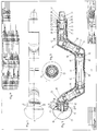
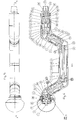
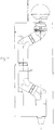
- FIG. 1-11 An attachment for a reamer cutting shell in accordance with the present invention is illustrated in Figures 1-11 .
- the reamer comprises six main assemblies, namely a universal conical connection spigot (part of the drive input hub), a reduction gearbox (part of the drive input hub), a body comprising a drive train, a reamer drive assembly (part of the drive output hub), a reamer shell retention mechanism (part of the drive output hub) and an acetabular reamer cutting shell, which is releasably attached to the drive output hub.
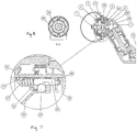
- the component parts of the reamers shown in Figures 1 and 2 and Figures 5 and 6 are listed in Figures 4 and 9 , respectively.
- a powered handpiece drives an epicyclic gearbox (6-12) inside the reamer attachment, thereby reducing the speed and increasing the torque.
- Drive is transferred along the reamer attachment's unique shape to the reamer shell cutter (24) drive hub via a series of drive shafts (34,35) and bevel gears (29).
- bevel gears (29) allows the drive to be taken through a much more acute angle in comparison with universal joints or flexible shafts.
- bevel gears (29) withstand far higher running or slam torques.
- the design of the final drive output hub incorporates the bearing/shaft assembly within the internal space envelope of the rear portion of the acetabular shell (24). This has the effect of reducing, to an absolute minimum, the distance between the distal end of the acetabular reamer cutting shell (24) and the rear of the angle head (1).
- the reamer attachment shown in Figures 1 and 2 has a unique acetabular reamer cutting shell (24) locking system, enabling the reamer shell cutter to be locked securely onto the drive hub (22) whilst the reamer is in use.
- the cutting shell is locked axially in place by two balls (44) which are radially held out into two corresponding holes within the driving collar on the reamer shell (24).
- the balls are held in the outward position by the plain portion on the two notched pins (46) which are secured onto the releasing collar (47).
- the whole releasing collar and notched pin assembly is spring loaded away from the distal end of the reamer shell (24).
- the drive hub incorporates two drive dogs, which locate into two corresponding slots on the rear portion of the reamer shell mounting collar, this provides the drive between the drive hub and the shell.
- typical angles of the drive shaft and bevel gears are between 20 and 80 degrees plus or minus from the axis but also between 20 and 75 degrees, 25 and 70 degrees, 30 and 65 degrees, 40 and 65 degrees, 45 and 65 degrees and 50 and 65 degrees plus or minus from the axis of the shaft.
- Aptly an angle of 60 degrees, or about 60 degrees plus or minus from the axis of the shaft may be used to give the unique shape of the attachment.
- the universal conical connection spigot assembly (49) is inserted into a surgical motor handpiece (not shown) with the output drive from the handpiece connecting to the input shaft attachment pinion (48) by means of a tang shaped drive end.
- the powered handpiece output speed is normally around 1000-1200 rpm.
- a reamer attachment having a universal conical connection spigot assembly (49) is a preferred embodiment of the present invention.
- Such reamer attachments are designed to be used with the De Soutter Medical MDX electric (battery) and MPX pneumatic surgical instrument systems.
- the conical connection spigot arrangement can be replaced with a conventional Hudson, Zimmer or other industry standard chucking system.
- Such configurations necessitate the use of a separate geared reamer attachment with its associated drawbacks.
- the reduction gearbox assembly reduces the output speed of the powered handpiece down to the required acetabular reaming speed, typically between 200 and 300 rpm.
- This speed reduction is achieved by a single stage planetary gearbox system.
- the attachment pinion (48) is supported on two bearings (11,13), the gear form on the pinion engaging on the planet wheels (46).
- the attachment pinion is sealed against water and steam ingress by a seal (31) assembled to the attachment pinion (48).
- the planet carrier (43) is supported on two bearings (12,10) and is driven by the resultant rotary motion created between the attachment pinion (48), the planet wheels (46) and the internal gear (44).
- a bevel gear (14) is mounted onto a shouldered spigot diameter formed on the distal end of the planet carrier (43).
- a key (28) transmits the drive between the planet carrier (43) and the bevel gear (14).
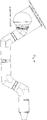
- the body (1-4) takes the drive train through a deformed U-shaped, or top hat shaped, series of bends around the patient's femoral head.
- This particular design comprises four separate bends with the output drive from the reamer preferably ending up being in line with the original axis of the handpiece output drive.
- the series of bends in the drive train is achieved by configuring four sets of bevel gears (14) arranged in such a manner that their axis of rotation form a typical angle to one another of 120 degrees.
- the bevel gear sets are connected by three shafts (19,20) that are supported on a number of bearings (10) mounted into the angled housings (2,3,4) of the body.
- the housings are connected by three turnbuckles (18) and supporting spacers (16,17) which control the correct dimensional relationships between the assembled components so ensuring the bevel gears (14) are correctly meshed.
- the transmission is therefore taken through four bends of 120 degrees each.
- the offset distance between the input axis from the handpiece to the secondary parallel transmission axis is typically around 50mm.
- the distance between the two bends, which defines the length of secondary parallel transmission axis, typically measures 140mm.
- the output shaft (6) is driven from the final set of bevel gears (14) which is supported on two bearings (8,9), which in turn are retained within the output housing (1).
- the drive between the output shaft and the end cap (5) is accomplished by dog drive machined onto the internal face of the end cap and the front of the shaft. The two items are secured together with a screw (7).
- the whole front-end reamer hub assembly is sealed against the ingress of liquid and steam by a seal (30) located between the internal annulus of the end cap (5) and the outside diameter of the output housing (1).
- a feature of the output hub assembly is that the output shaft (6) and supporting bearing assembly (8,9) is so arranged that it partially protrudes into, and is thereby incorporated within, the internal space envelope of the rear portion of the acetabular reamer shell (55). This has the effect of reducing, to the absolute minimum, the distance between the distal end of the acetabular reamer shell (55) and the back face of the output housing (1).
- the end cap (5) acts as the location spigot for the rear annulus of the reamer shell (55), whilst containing a quick release locking mechanism to retain the reamer shell.
- the locking mechanism comprises a series of interacting notched pins (37) and balls (33) which secure the reamer shell (55) to the end cap (5).
- the notched pins are pushed rearwards by springs (51) which are retained within the end cap (5) assembly.
- the notched pins are secured into the releasing collar (38) and are stopped from rotation by having flats machined onto their ends, the flatted notched pin ends mating with corresponding D holes formed into the releasing collar (38).
- the holes in the retaining ring (32) are sized such that they keep the balls (33) captive whilst at the same time they allow the balls (33) to partially protrude beyond the retaining ring (32) diameter when acting on the full diameter of the notched pins (37).
- the reamer shell (55) is released from the end cap assembly by pushing the spring-loaded releasing collar (38) towards the distal end of the device, this action allows the notched portion of the notched pins (37) to line up with the balls (33) thereby allowing the balls to retract inwardly.
- the balls retracting below the outside diameter of the end cap assembly allows the reamer shell (55) to be slid off distally.
- the drive between the reamer shell (55) and the end cap (5) is achieved by the inclusion of two lugs that are machined onto the rear portion of the end cap (5). These lugs mate with two corresponding notches that are formed into the rear location diameter on the reamer shell (55).
- the acetabular reamer shell (55) is constructed in a similar fashion to those commonly used for acetabulum reaming procedures. However, reamer shells used with the attachment of the present invention are configured to contain two drive notches formed into the rear location diameter.
- An attachment according to the present invention is a dedicated device that improves the surgeon's ability to perform various acetabular reaming procedures where access to the surgical site is limited. Typically access is restricted in hip re-surfacing procedures and least invasive total hip replacement (THR) hip surgery.
- THR total hip replacement
- the uniquely shaped reamer attachment allows the surgeon to make a much smaller incision than would otherwise be required when using a conventional in-line acetabular reamer shaft assembly.
- Devices according to the present invention enable the thrust line to be kept perpendicular to the cutting site when performing least invasive surgical techniques.
- a problem associated with the hip re-surfacing procedure is that the femoral head obscures the cutting site. Additionally the distance between the femoral head and the acetabulum is severely restricted when the surgeon inserts the reamer head/shell assembly into the surgical site.
- the attachment according to the present invention overcomes these problems by enabling the drive train from the powered handpiece to curve around the obscuring femoral head so that cutting behind the obscuring femoral head can occur.
- Reamer attachments optimise the available space by utilising a very compact drive train mechanism, which has a very acute angle of approach and which incorporates both the final angled drive hub assembly and the reamer shell retention/releasing mechanism.
- the use of bevel gears allows the drive to be taken through a much more acute angle in comparison with alternative transmission systems such as universal joints or flexible shafts.
- Bevel gears can withstand far higher running or slam/stall torques which are often encountered in acetabular reaming procedures.
- Attachments according to the present invention incorporate a reduction gearbox, typically having a gearing reduction of 5:1, which eliminates the necessity of utilising a separate geared reamer attachment connected to the motor handpiece.
- a reduction gearbox typically having a gearing reduction of 5:1
- the weight, length and general bulk of the powered handpiece/attachment combination is minimised, As there is only one coupling point between the handpiece and the reamer attachment the complete system becomes far more robust and rigid than would normally be the case with a separate secondary attachment containing the reduction gearbox.
- a further advantage of this configuration is that the outer casing of the reamer attachment is both rotationally and axially secured into the handpiece by the universal conical locking mechanism. As a result, the reaming reaction torque is transmitted back into the pistol grip shaped handpiece, which in turn eliminates the necessity of incorporating a side handle onto the reamer attachment.
- attachment of the present invention has been described in relation to a reamer, it can be used as a tool driver for other surgical instruments (tools).
Landscapes
- Health & Medical Sciences (AREA)
- Surgery (AREA)
- Life Sciences & Earth Sciences (AREA)
- Biomedical Technology (AREA)
- Medical Informatics (AREA)
- Orthopedic Medicine & Surgery (AREA)
- Oral & Maxillofacial Surgery (AREA)
- Engineering & Computer Science (AREA)
- Dentistry (AREA)
- Heart & Thoracic Surgery (AREA)
- Nuclear Medicine, Radiotherapy & Molecular Imaging (AREA)
- Molecular Biology (AREA)
- Animal Behavior & Ethology (AREA)
- General Health & Medical Sciences (AREA)
- Public Health (AREA)
- Veterinary Medicine (AREA)
- Surgical Instruments (AREA)
- Prostheses (AREA)
Applications Claiming Priority (2)
| Application Number | Priority Date | Filing Date | Title |
|---|---|---|---|
| GBGB0503529.0A GB0503529D0 (en) | 2005-02-21 | 2005-02-21 | Medical device |
| PCT/GB2006/000605 WO2006087584A1 (en) | 2005-02-21 | 2006-02-21 | Drive shaft for a surgical instrument |
Publications (2)
| Publication Number | Publication Date |
|---|---|
| EP1850761A1 EP1850761A1 (en) | 2007-11-07 |
| EP1850761B1 true EP1850761B1 (en) | 2020-02-12 |
Family
ID=34401039
Family Applications (1)
| Application Number | Title | Priority Date | Filing Date |
|---|---|---|---|
| EP06709840.0A Active EP1850761B1 (en) | 2005-02-21 | 2006-02-21 | Drive shaft for a surgical instrument |
Country Status (7)
| Country | Link |
|---|---|
| US (1) | US9066730B2 (enExample) |
| EP (1) | EP1850761B1 (enExample) |
| JP (2) | JP5355895B2 (enExample) |
| AU (1) | AU2006215440A1 (enExample) |
| CA (1) | CA2601920A1 (enExample) |
| GB (1) | GB0503529D0 (enExample) |
| WO (1) | WO2006087584A1 (enExample) |
Families Citing this family (22)
| Publication number | Priority date | Publication date | Assignee | Title |
|---|---|---|---|---|
| JP5388106B2 (ja) * | 2009-03-12 | 2014-01-15 | HOYA Technosurgical株式会社 | 医療用ドリル装置 |
| US9078672B1 (en) | 2010-11-05 | 2015-07-14 | Greatbatch Medical S.A. | Carbon reamer handle |
| FR2967046A1 (fr) | 2010-11-10 | 2012-05-11 | Tornier Sa | Fraiseuse orthopedique de preparation osseuse, en particulier de preparation glenoidienne |
| WO2014123874A1 (en) * | 2013-02-05 | 2014-08-14 | Stryker Corporation | System for performing surgical procedures with a tool tube that is bent to provide a view of the tissue working member at the end of the tube |
| US9814471B2 (en) * | 2013-03-11 | 2017-11-14 | Catalyst Orthoscience Inc. | Glenoid arthroplasty and offset reamers |
| US20170319348A1 (en) | 2015-08-10 | 2017-11-09 | Catalyst Orthoscience Inc. | Arthroplasty prostheses with multi-axis fixation |
| US11007063B2 (en) | 2013-03-11 | 2021-05-18 | Catalyst Orthoscience Inc. | Offset reamers |
| USD730522S1 (en) | 2013-03-11 | 2015-05-26 | Catalyst Orthopaedics Llc | Implant |
| US10973646B2 (en) | 2013-03-11 | 2021-04-13 | Catalyst Orthoscience Inc. | Stabilized drill guide |
| US10588642B2 (en) * | 2014-05-15 | 2020-03-17 | Gauthier Biomedical, Inc. | Molding process and products formed thereby |
| US9814470B2 (en) | 2014-05-22 | 2017-11-14 | Symmetry Medical Manufacturing, Inc. | Offset orthopaedic reamer handle |
| US11234826B2 (en) | 2014-06-30 | 2022-02-01 | Howmedica Osteonics Corp. | Augmented glenoid components and devices for implanting the same |
| US10028838B2 (en) | 2014-06-30 | 2018-07-24 | Tornier, Inc. | Augmented glenoid components and devices for implanting the same |
| US20160135862A1 (en) * | 2014-11-17 | 2016-05-19 | Spinal Elements, Inc. | Curved surgical tools |
| WO2018022227A1 (en) | 2016-07-28 | 2018-02-01 | Tornier, Inc. | Stemless prosthesis anchor component |
| WO2019092615A1 (en) * | 2017-11-07 | 2019-05-16 | Incipio Devices Sa | Offset reamer driver with remote release mechanism |
| GB201802787D0 (en) * | 2018-02-21 | 2018-04-04 | Depuy Ireland Ultd Co | Acetabular reamer handle and method of reaming an acetabulum |
| AU2020204539B2 (en) | 2019-07-12 | 2024-10-31 | Howmedica Osteonics Corp. | Augmented glenoid design |
| US11426285B2 (en) | 2019-09-05 | 2022-08-30 | Howmedica Osteonics Corp. | Truss glenoid augment |
| AU2021200854A1 (en) | 2020-03-03 | 2021-09-16 | Howmedica Osteonics Corp. | Glenoid implant with additively manufactured fixation posts |
| US12279839B2 (en) * | 2020-04-24 | 2025-04-22 | Orthosoft Ulc | End effector for robotic shoulder arthroplasty |
| CN114668452A (zh) * | 2022-04-25 | 2022-06-28 | 天衍医疗器材有限公司 | 一种适用于机器人手术的双弯髋臼锉把持器 |
Family Cites Families (16)
| Publication number | Priority date | Publication date | Assignee | Title |
|---|---|---|---|---|
| US5236433A (en) * | 1991-05-08 | 1993-08-17 | Othy, Inc. | Tool driver |
| JPH0751136B2 (ja) * | 1992-09-02 | 1995-06-05 | 株式会社モリタ製作所 | 歯科用ハンドピースの駆動装置 |
| JPH08271536A (ja) * | 1995-03-28 | 1996-10-18 | Nissan Diesel Motor Co Ltd | 車両のメータケーブル装置 |
| EP1256322B1 (en) * | 1996-09-24 | 2005-12-07 | Xomed Surgical Products, Inc. | Surgical blade assembly |
| GB2323036B (en) * | 1997-03-14 | 2001-04-11 | Finsbury | Prosthetic implant and surgical tool |
| DE29720616U1 (de) * | 1997-04-18 | 1998-08-20 | Kaltenbach & Voigt Gmbh & Co, 88400 Biberach | Handstück für medizinische Zwecke, insbesondere für eine ärztliche oder zahnärztliche Behandlungseinrichtung, vorzugsweise für eine spanabhebende Bearbeitung eines Zahn-Wurzelkanals |
| WO1999058076A1 (de) * | 1998-05-08 | 1999-11-18 | Heribert Schmid | Arbeitsgerät für bohr-, schneid- und schraubwerkzeuge zu medizinischen zwecken |
| US6312438B1 (en) * | 2000-02-01 | 2001-11-06 | Medtronic Xomed, Inc. | Rotary bur instruments having bur tips with aspiration passages |
| US6733218B2 (en) * | 2001-09-25 | 2004-05-11 | The Anspach Effort, Inc. | High speed surgical instrument |
| AU2002242659A1 (en) * | 2002-01-11 | 2003-07-24 | Waldemar Link (Gmbh And Co.) | Surgical instrument for routing out the hip socket |
| US7819875B2 (en) * | 2002-02-08 | 2010-10-26 | Gursharan Singh Chana | Surgical devices and methods of use |
| EP1499248B1 (en) * | 2002-04-30 | 2010-03-10 | Greatbatch Medical SA | Reamer spindle for minimally invasive joint surgery |
| US7326215B2 (en) * | 2002-10-30 | 2008-02-05 | Symmetry Medical, Inc. | Curved surgical tool driver |
| US7004946B2 (en) * | 2002-10-30 | 2006-02-28 | Symmetry Medical, Inc. | Acetabular cup impactor |
| US8277474B2 (en) * | 2004-05-26 | 2012-10-02 | Medtronic, Inc. | Surgical cutting instrument |
| US20060276797A1 (en) * | 2005-05-24 | 2006-12-07 | Gary Botimer | Expandable reaming device |
-
2005
- 2005-02-21 GB GBGB0503529.0A patent/GB0503529D0/en not_active Ceased
-
2006
- 2006-02-21 EP EP06709840.0A patent/EP1850761B1/en active Active
- 2006-02-21 CA CA002601920A patent/CA2601920A1/en not_active Abandoned
- 2006-02-21 US US11/816,777 patent/US9066730B2/en active Active
- 2006-02-21 AU AU2006215440A patent/AU2006215440A1/en not_active Abandoned
- 2006-02-21 JP JP2007555709A patent/JP5355895B2/ja not_active Expired - Fee Related
- 2006-02-21 WO PCT/GB2006/000605 patent/WO2006087584A1/en not_active Ceased
-
2013
- 2013-07-08 JP JP2013142763A patent/JP2013226445A/ja active Pending
Non-Patent Citations (1)
| Title |
|---|
| None * |
Also Published As
| Publication number | Publication date |
|---|---|
| AU2006215440A1 (en) | 2006-08-24 |
| JP5355895B2 (ja) | 2013-11-27 |
| WO2006087584A1 (en) | 2006-08-24 |
| GB0503529D0 (en) | 2005-03-30 |
| EP1850761A1 (en) | 2007-11-07 |
| CA2601920A1 (en) | 2006-08-24 |
| JP2013226445A (ja) | 2013-11-07 |
| JP2008529701A (ja) | 2008-08-07 |
| US20080287952A1 (en) | 2008-11-20 |
| US9066730B2 (en) | 2015-06-30 |
Similar Documents
| Publication | Publication Date | Title |
|---|---|---|
| EP1850761B1 (en) | Drive shaft for a surgical instrument | |
| EP3668423B1 (en) | Surgical handpiece for measuring depth of bore holes and related accessories | |
| US9615835B2 (en) | Drill attachment for cannulated surgical drills | |
| JP6748672B2 (ja) | 動的係止装置 | |
| US20100204702A1 (en) | Precision assembleable surgical tool handle | |
| EP1386587A2 (en) | Surgical instrument with rotary cutting member and quick release coupling arrangement | |
| CN103565487A (zh) | 机电手术系统 | |
| US20220211391A1 (en) | Surgical Handpiece System for Depth Measurement and Related Accessories | |
| CN218572248U (zh) | 关节成型执行器及外科手术系统 | |
| JP7676715B2 (ja) | 寛骨臼リーマハンドル及び寛骨臼をリーミングする方法 | |
| AU2012201198A1 (en) | Drive shaft for a surgical instrument | |
| US11523833B2 (en) | Surgical rotary tool | |
| US20230397916A1 (en) | Surgical Attachments for a Surgical Handpiece System | |
| EP3755245B1 (en) | Acetabular reamer handle | |
| US20250255618A1 (en) | Surgical Handpiece System For Driving Surgical Pins And Related Accessories | |
| CN117503259A (zh) | 一种脊柱内镜镜外动力可视环锯 |
Legal Events
| Date | Code | Title | Description |
|---|---|---|---|
| PUAI | Public reference made under article 153(3) epc to a published international application that has entered the european phase |
Free format text: ORIGINAL CODE: 0009012 |
|
| 17P | Request for examination filed |
Effective date: 20070813 |
|
| AK | Designated contracting states |
Kind code of ref document: A1 Designated state(s): AT BE BG CH CY CZ DE DK EE ES FI FR GB GR HU IE IS IT LI LT LU LV MC NL PL PT RO SE SI SK TR |
|
| DAX | Request for extension of the european patent (deleted) | ||
| 17Q | First examination report despatched |
Effective date: 20100222 |
|
| REG | Reference to a national code |
Ref country code: DE Ref legal event code: R079 Ref document number: 602006059110 Country of ref document: DE Free format text: PREVIOUS MAIN CLASS: A61B0017160000 Ipc: A61B0017000000 |
|
| RIC1 | Information provided on ipc code assigned before grant |
Ipc: A61B 17/00 20060101AFI20190320BHEP Ipc: A61B 17/16 20060101ALI20190320BHEP |
|
| GRAP | Despatch of communication of intention to grant a patent |
Free format text: ORIGINAL CODE: EPIDOSNIGR1 |
|
| STAA | Information on the status of an ep patent application or granted ep patent |
Free format text: STATUS: GRANT OF PATENT IS INTENDED |
|
| INTG | Intention to grant announced |
Effective date: 20190426 |
|
| RAP1 | Party data changed (applicant data changed or rights of an application transferred) |
Owner name: DE SOUTTER MEDICAL LIMITED Owner name: SMITH & NEPHEW PLC |
|
| GRAS | Grant fee paid |
Free format text: ORIGINAL CODE: EPIDOSNIGR3 |
|
| GRAA | (expected) grant |
Free format text: ORIGINAL CODE: 0009210 |
|
| STAA | Information on the status of an ep patent application or granted ep patent |
Free format text: STATUS: THE PATENT HAS BEEN GRANTED |
|
| REG | Reference to a national code |
Ref country code: DE Ref legal event code: R081 Ref document number: 602006059110 Country of ref document: DE Owner name: SMITH & NEPHEW PLC, WATFORD, GB Free format text: FORMER OWNERS: DE SOUTTER MEDICAL LTD., BERKHAMSTED, HERTFORDSHIRE, GB; SMITH & NEPHEW PLC, LONDON, GB Ref country code: DE Ref legal event code: R081 Ref document number: 602006059110 Country of ref document: DE Owner name: DE SOUTTER MEDICAL LTD., BERKHAMSTED, GB Free format text: FORMER OWNERS: DE SOUTTER MEDICAL LTD., BERKHAMSTED, HERTFORDSHIRE, GB; SMITH & NEPHEW PLC, LONDON, GB |
|
| AK | Designated contracting states |
Kind code of ref document: B1 Designated state(s): AT BE BG CH CY CZ DE DK EE ES FI FR GB GR HU IE IS IT LI LT LU LV MC NL PL PT RO SE SI SK TR |
|
| REG | Reference to a national code |
Ref country code: GB Ref legal event code: FG4D |
|
| REG | Reference to a national code |
Ref country code: CH Ref legal event code: EP |
|
| REG | Reference to a national code |
Ref country code: AT Ref legal event code: REF Ref document number: 1231038 Country of ref document: AT Kind code of ref document: T Effective date: 20200215 |
|
| REG | Reference to a national code |
Ref country code: IE Ref legal event code: FG4D |
|
| REG | Reference to a national code |
Ref country code: DE Ref legal event code: R096 Ref document number: 602006059110 Country of ref document: DE |
|
| REG | Reference to a national code |
Ref country code: NL Ref legal event code: FP |
|
| PG25 | Lapsed in a contracting state [announced via postgrant information from national office to epo] |
Ref country code: FI Free format text: LAPSE BECAUSE OF FAILURE TO SUBMIT A TRANSLATION OF THE DESCRIPTION OR TO PAY THE FEE WITHIN THE PRESCRIBED TIME-LIMIT Effective date: 20200212 |
|
| REG | Reference to a national code |
Ref country code: LT Ref legal event code: MG4D |
|
| PG25 | Lapsed in a contracting state [announced via postgrant information from national office to epo] |
Ref country code: BG Free format text: LAPSE BECAUSE OF FAILURE TO SUBMIT A TRANSLATION OF THE DESCRIPTION OR TO PAY THE FEE WITHIN THE PRESCRIBED TIME-LIMIT Effective date: 20200512 Ref country code: SE Free format text: LAPSE BECAUSE OF FAILURE TO SUBMIT A TRANSLATION OF THE DESCRIPTION OR TO PAY THE FEE WITHIN THE PRESCRIBED TIME-LIMIT Effective date: 20200212 Ref country code: IS Free format text: LAPSE BECAUSE OF FAILURE TO SUBMIT A TRANSLATION OF THE DESCRIPTION OR TO PAY THE FEE WITHIN THE PRESCRIBED TIME-LIMIT Effective date: 20200612 Ref country code: LV Free format text: LAPSE BECAUSE OF FAILURE TO SUBMIT A TRANSLATION OF THE DESCRIPTION OR TO PAY THE FEE WITHIN THE PRESCRIBED TIME-LIMIT Effective date: 20200212 Ref country code: GR Free format text: LAPSE BECAUSE OF FAILURE TO SUBMIT A TRANSLATION OF THE DESCRIPTION OR TO PAY THE FEE WITHIN THE PRESCRIBED TIME-LIMIT Effective date: 20200513 |
|
| REG | Reference to a national code |
Ref country code: BE Ref legal event code: MM Effective date: 20200229 |
|
| PG25 | Lapsed in a contracting state [announced via postgrant information from national office to epo] |
Ref country code: CZ Free format text: LAPSE BECAUSE OF FAILURE TO SUBMIT A TRANSLATION OF THE DESCRIPTION OR TO PAY THE FEE WITHIN THE PRESCRIBED TIME-LIMIT Effective date: 20200212 Ref country code: SK Free format text: LAPSE BECAUSE OF FAILURE TO SUBMIT A TRANSLATION OF THE DESCRIPTION OR TO PAY THE FEE WITHIN THE PRESCRIBED TIME-LIMIT Effective date: 20200212 Ref country code: DK Free format text: LAPSE BECAUSE OF FAILURE TO SUBMIT A TRANSLATION OF THE DESCRIPTION OR TO PAY THE FEE WITHIN THE PRESCRIBED TIME-LIMIT Effective date: 20200212 Ref country code: EE Free format text: LAPSE BECAUSE OF FAILURE TO SUBMIT A TRANSLATION OF THE DESCRIPTION OR TO PAY THE FEE WITHIN THE PRESCRIBED TIME-LIMIT Effective date: 20200212 Ref country code: LT Free format text: LAPSE BECAUSE OF FAILURE TO SUBMIT A TRANSLATION OF THE DESCRIPTION OR TO PAY THE FEE WITHIN THE PRESCRIBED TIME-LIMIT Effective date: 20200212 Ref country code: RO Free format text: LAPSE BECAUSE OF FAILURE TO SUBMIT A TRANSLATION OF THE DESCRIPTION OR TO PAY THE FEE WITHIN THE PRESCRIBED TIME-LIMIT Effective date: 20200212 Ref country code: LU Free format text: LAPSE BECAUSE OF NON-PAYMENT OF DUE FEES Effective date: 20200221 Ref country code: ES Free format text: LAPSE BECAUSE OF FAILURE TO SUBMIT A TRANSLATION OF THE DESCRIPTION OR TO PAY THE FEE WITHIN THE PRESCRIBED TIME-LIMIT Effective date: 20200212 Ref country code: PT Free format text: LAPSE BECAUSE OF FAILURE TO SUBMIT A TRANSLATION OF THE DESCRIPTION OR TO PAY THE FEE WITHIN THE PRESCRIBED TIME-LIMIT Effective date: 20200705 |
|
| REG | Reference to a national code |
Ref country code: DE Ref legal event code: R097 Ref document number: 602006059110 Country of ref document: DE |
|
| REG | Reference to a national code |
Ref country code: AT Ref legal event code: MK05 Ref document number: 1231038 Country of ref document: AT Kind code of ref document: T Effective date: 20200212 |
|
| PG25 | Lapsed in a contracting state [announced via postgrant information from national office to epo] |
Ref country code: MC Free format text: LAPSE BECAUSE OF FAILURE TO SUBMIT A TRANSLATION OF THE DESCRIPTION OR TO PAY THE FEE WITHIN THE PRESCRIBED TIME-LIMIT Effective date: 20200212 |
|
| PLBE | No opposition filed within time limit |
Free format text: ORIGINAL CODE: 0009261 |
|
| STAA | Information on the status of an ep patent application or granted ep patent |
Free format text: STATUS: NO OPPOSITION FILED WITHIN TIME LIMIT |
|
| 26N | No opposition filed |
Effective date: 20201113 |
|
| PG25 | Lapsed in a contracting state [announced via postgrant information from national office to epo] |
Ref country code: AT Free format text: LAPSE BECAUSE OF FAILURE TO SUBMIT A TRANSLATION OF THE DESCRIPTION OR TO PAY THE FEE WITHIN THE PRESCRIBED TIME-LIMIT Effective date: 20200212 Ref country code: IT Free format text: LAPSE BECAUSE OF FAILURE TO SUBMIT A TRANSLATION OF THE DESCRIPTION OR TO PAY THE FEE WITHIN THE PRESCRIBED TIME-LIMIT Effective date: 20200212 Ref country code: IE Free format text: LAPSE BECAUSE OF NON-PAYMENT OF DUE FEES Effective date: 20200221 |
|
| PG25 | Lapsed in a contracting state [announced via postgrant information from national office to epo] |
Ref country code: PL Free format text: LAPSE BECAUSE OF FAILURE TO SUBMIT A TRANSLATION OF THE DESCRIPTION OR TO PAY THE FEE WITHIN THE PRESCRIBED TIME-LIMIT Effective date: 20200212 Ref country code: SI Free format text: LAPSE BECAUSE OF FAILURE TO SUBMIT A TRANSLATION OF THE DESCRIPTION OR TO PAY THE FEE WITHIN THE PRESCRIBED TIME-LIMIT Effective date: 20200212 Ref country code: BE Free format text: LAPSE BECAUSE OF NON-PAYMENT OF DUE FEES Effective date: 20200229 |
|
| PG25 | Lapsed in a contracting state [announced via postgrant information from national office to epo] |
Ref country code: TR Free format text: LAPSE BECAUSE OF FAILURE TO SUBMIT A TRANSLATION OF THE DESCRIPTION OR TO PAY THE FEE WITHIN THE PRESCRIBED TIME-LIMIT Effective date: 20200212 Ref country code: CY Free format text: LAPSE BECAUSE OF FAILURE TO SUBMIT A TRANSLATION OF THE DESCRIPTION OR TO PAY THE FEE WITHIN THE PRESCRIBED TIME-LIMIT Effective date: 20200212 |
|
| PGFP | Annual fee paid to national office [announced via postgrant information from national office to epo] |
Ref country code: NL Payment date: 20230113 Year of fee payment: 18 |
|
| REG | Reference to a national code |
Ref country code: NL Ref legal event code: MM Effective date: 20240301 |
|
| PG25 | Lapsed in a contracting state [announced via postgrant information from national office to epo] |
Ref country code: NL Free format text: LAPSE BECAUSE OF NON-PAYMENT OF DUE FEES Effective date: 20240301 |
|
| PG25 | Lapsed in a contracting state [announced via postgrant information from national office to epo] |
Ref country code: NL Free format text: LAPSE BECAUSE OF NON-PAYMENT OF DUE FEES Effective date: 20240301 |
|
| PGFP | Annual fee paid to national office [announced via postgrant information from national office to epo] |
Ref country code: FR Payment date: 20241223 Year of fee payment: 20 |
|
| PGFP | Annual fee paid to national office [announced via postgrant information from national office to epo] |
Ref country code: DE Payment date: 20241224 Year of fee payment: 20 |
|
| PGFP | Annual fee paid to national office [announced via postgrant information from national office to epo] |
Ref country code: CH Payment date: 20250301 Year of fee payment: 20 |
|
| PGFP | Annual fee paid to national office [announced via postgrant information from national office to epo] |
Ref country code: GB Payment date: 20250102 Year of fee payment: 20 |