EP1850707B1 - Warendarbietungsanordnung - Google Patents
Warendarbietungsanordnung Download PDFInfo
- Publication number
- EP1850707B1 EP1850707B1 EP05701922A EP05701922A EP1850707B1 EP 1850707 B1 EP1850707 B1 EP 1850707B1 EP 05701922 A EP05701922 A EP 05701922A EP 05701922 A EP05701922 A EP 05701922A EP 1850707 B1 EP1850707 B1 EP 1850707B1
- Authority
- EP
- European Patent Office
- Prior art keywords
- hanger
- anchor plate
- display assembly
- merchandise display
- bar
- Prior art date
- Legal status (The legal status is an assumption and is not a legal conclusion. Google has not performed a legal analysis and makes no representation as to the accuracy of the status listed.)
- Expired - Lifetime
Links
- 238000005728 strengthening Methods 0.000 claims description 8
- 230000000295 complement effect Effects 0.000 claims description 5
- 230000003014 reinforcing effect Effects 0.000 claims description 5
- 239000004743 Polypropylene Substances 0.000 description 3
- 238000010276 construction Methods 0.000 description 3
- 229920001155 polypropylene Polymers 0.000 description 3
- 239000004677 Nylon Substances 0.000 description 2
- 239000000463 material Substances 0.000 description 2
- 229920001778 nylon Polymers 0.000 description 2
- -1 polypropylene Polymers 0.000 description 2
- 239000011521 glass Substances 0.000 description 1
- 229910052500 inorganic mineral Inorganic materials 0.000 description 1
- 239000011707 mineral Substances 0.000 description 1
- 238000004806 packaging method and process Methods 0.000 description 1
- 239000004033 plastic Substances 0.000 description 1
- 229920003023 plastic Polymers 0.000 description 1
- 229920000515 polycarbonate Polymers 0.000 description 1
- 239000004417 polycarbonate Substances 0.000 description 1
- 230000000717 retained effect Effects 0.000 description 1
Images



Classifications
-
- A—HUMAN NECESSITIES
- A47—FURNITURE; DOMESTIC ARTICLES OR APPLIANCES; COFFEE MILLS; SPICE MILLS; SUCTION CLEANERS IN GENERAL
- A47F—SPECIAL FURNITURE, FITTINGS, OR ACCESSORIES FOR SHOPS, STOREHOUSES, BARS, RESTAURANTS OR THE LIKE; PAYING COUNTERS
- A47F5/00—Show stands, hangers, or shelves characterised by their constructional features
- A47F5/08—Show stands, hangers, or shelves characterised by their constructional features secured to the wall, ceiling, or the like; Wall-bracket display devices
- A47F5/0807—Display panels, grids or rods used for suspending merchandise or cards supporting articles; Movable brackets therefor
- A47F5/0815—Panel constructions with apertures for article supports, e.g. hooks
- A47F5/0823—Article supports for peg-boards
Definitions
- This invention relates to a merchandise display assembly.
- the invention relates to a merchandise display assembly in which a display element may be hingedly mounted on anchor plate.
- the display of merchandise at Point of Sale (POS) or Point of Purchase (POP) is a key factor in many retail operations.
- the retailer must take into account such factors as the ease with which the display means may be transported from one location to another, the accessibility of the displayed merchandise to customers, efficient use of space, the cost of the display means used, and safety and security issues.
- a widely used POS / POP display system involves an apertured board to which are attached a plurality of elongate protruding hooks or hangers. The merchandise is suspended from these hangers, often in carded display packaging.
- Eurohook is a double-pronged hanger, the twin prongs extending in parallel from a fixed base plate designed to attach to a merchandise display by means of clips, tabs, hooks or spikes provided on the reverse thereof.
- the twin prongs are generally angled part-way along their length so as to enable packaged goods to be retained on the hanger.
- a cross-piece bridges the ends of the prongs both providing strength and creating a squared end, thus forming a location for attaching a swing label showing, for example, the price of the merchandise displayed.
- the Eurohook thus has a number of advantages over single pronged systems employed elsewhere.
- the double-pronged structure provides greater strength, allowing the Eurohook to be used with a wider range of merchandise.
- single pronged hangers do not so readily provide a location for the attachment of swing labels.
- the present invention stems from the realisation that, despite the widespread use of the Eurohook, it does suffer from at least one shortcoming, due to its use of a fixed back plate.
- the hangers must therefore be supplied separately from the boards and attached once the display boards are in position in the retail environment.
- the hangers must be removed from the boards and then re-attached once the boards have been transported to their new location, or removed from storage. Each of these operations is time consuming, represents an inefficient use of labour, and is therefore costly.
- the present invention seeks address this previously unaddressed problem, by providing a hinged Eurohook. It is envisaged that this will enable display boards to be supplied pre-fitted with the hangers, in a flat-packed condition for storage and transport, thus enabling greater flexibility, quicker assembly of POS displays, and therefore costs savings.
- a merchandise display assembly comprising an anchor plate adapted to be mounted on a display board, and a double-pronged hanger adapted to be mounted on the anchor plate, characterised in that : the anchor plate comprises a single elongate hook member projecting therefrom and having a single continuous receiving surface, and the double-pronged hanger has a bar formed at one end thereof adapted to be received by said single elongate hook member, such that said hanger is capable of being hingedly mounted on the anchor plate for rotational movement between a first storage position wherein the hanger is disposed substantially parallel to the plane of the anchor plate, and a second operational position, wherein the hanger is disposed substantially perpendicular to the plane of the anchor plate.
- the hanger is adapted to be removably mounted on the anchor plate, attachment and detachment only being possible when the hanger is arranged in its first storage position.
- the assembly will preferably be adapted such that the hanger may be locked in at least its second operational position.
- the hinged, or hinged and removable, mounting of the hanger on the anchor plate is achieved by the co-operation of a bar formed at a first end of the hanger, with a single elongate hook member projecting from the anchor plate, said hook member having a single continuous receiving surface of complementary shape to that of the hanger bar.
- the elongate hook member has a single continuous receiving surface having an inner profile complementary to the shape of the hanger bar.
- the hook member has an axial extension, x, substantially equal to the length of the bar.
- the hook member may additionally be provided with one or more reinforcing buttresses.
- Each prong of the hanger has, at the first end thereof, a depending support leg associated therewith, said support legs abutting against the anchor plate when the hanger is in its second operational position.
- the hanger bar bridges the twin prongs, extending between the pair of support legs.
- a splay is provided in the upper surface of each prong at the first end thereof adjacent the boundary with the hanger bar, to facilitate the rotational movement of the hanger between its first (storage) and second (operational) positions.
- the hanger preferably comprises one or more of the following features, namely: a pair of triangular support ribs, one extending between each support leg and its associated prong; an inclined end section at the second end of the hanger, said section being formed by an angled junction in each prong; a strengthening plate bridging the two prongs, adjacent the angled junction; and a cross-piece bridging the two prongs at the second end of the hanger.
- the anchor plate is preferably provided with one or more upper tabs and one or more lower tabs for mounting on a display board. Most preferably, the anchor plate is provided with two upper tabs and one lower tab.
- the anchor plate and the hanger are preferably formed from plastics materials comprising one or more such materials selected from nylon, polycarbonate (PC), polypropylene (PPE), and glass or mineral filled nylon or polypropylene.
- anchor plate utilised in the present invention could be adapted for use with a range of merchandise display elements, not necessarily limited to double-pronged hangers such as the Eurohook.
- the anchor plate is preferably adapted such that said merchandise display element may be removably mounted thereon.
- the anchor plate can thus be used in combination with a range of interchangeable merchandise display elements, each having a bar adapted to be received by the elongate hook member of the anchor plate.
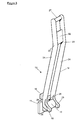
- FIG. 1 there is shown an anchor plate 11 and a hanger 12, which when assembled together form a first embodiment of merchandise display assembly, generally indicated 10.
- the anchor plate 11 has an elongate hook member 13 having a single continuous inner receiving surface 14 of complementary shape to a bar 15 provided on the hanger 12.
- the axial extension, x of the elongate hook member 13 is at least double its largest internal diameter, y .
- the axial extension, x, of the elongate hook member 13 is also substantially equal to the length of the bar 15.
- the anchor plate 11 is provided with an upper tab 16 and a lower tab (not visible in Figure 1 ) as will be described in more detail subsequently with reference to Figures 5 and 7 .
- the hanger 12 comprises a pair of parallel prongs 24, bridged at one end thereof by the bar 15.
- a support leg 25 depends from each prong 24 at said one end of the hanger 12, with a strengthening rib 18 provided between each support leg 25 and its associated prong 24.
- a splay 26 is provided in the upper surface of each prong 24 at said one end of the hanger 12 adjacent the bar 15.
- the prongs 24 are bridged by a crosspiece 27 which in use may be adapted to receive a swing label (not shown) presenting information about the merchandise on display. Further strength and rigidity is imparted to the hanger 12 by a strengthening plate 32 which bridges the prongs 24 near to said other end of the hanger 12. A junction 33 is formed in each prong 24 adjacent to the strengthening plate, such that the portion of the hanger 12 between said junction 33 and said crosspiece 27 is angled relative to the remainder of the hanger 12.
- the hanger 12 is mounted on the anchor plate 11 by locating the bar 15 (not visible in Figure 2 ) in the elongate hook member 13 to form the first embodiment of merchandise display assembly 10 according to the present invention.
- the assembly 10 is shown in Figure 2 with the hanger 12 in its operational position, with the prongs 24 arranged generally perpendicular to the anchor plate 11 and the support legs 25 abutting against the anchor plate 11. In this operational position, the angled section of the hanger 12 between the junction 33 and the crosspiece 27 is ready to receive goods for display.
- FIG. 3 there is shown the first embodiment of merchandise display assembly 10, with the hanger 12 arranged in its storage position.
- the prongs 24 are arranged generally parallel to the anchor plate 11, with the splayed surfaces 26 of said prongs 24 abutting against said anchor plate 11.
- This position is used for storage and transportation of the merchandise display assembly 10 when mounted on a display board (not shown).
- the storage position must also be used when attaching the hanger 12 to the anchor plate 11 by inserting the bar 15 into the hook member 13, and when detaching the hanger 12 from the anchor plate 11 by removing the bar 15 from the hook member 13.
- FIG. 4 there is shown a second embodiment of merchandise display assembly, generally indicated 20.
- the hanger 22 of the second embodiment 20 is broadly equivalent to the hanger 12 of the first embodiment 10 described previously with reference to Figures 1 to 3 , except that the strengthening rib 28 is triangular in shape, rather than having a curved profile as in the strengthening rib 18 of the hanger 12 of the first embodiment 10.
- the triangular shape of the rib 28 imparts greater strength and rigidity to the hanger 22.
- the anchor plate 21 of the second embodiment 20 is also similar to the anchor plate 11 of the first embodiment, differing only in the construction of the elongate hook member 23.
- the elongate hook member 23 still has a single continuous receiving surface 14 and an axial extension, x , at least double its largest diameter, y , and substantially equal to the length of the bar 15.
- the hook member 23 differs from its counterpart 13 from the first embodiment 10 in that it is additionally provided with reinforcing buttresses 34 at either end thereof.
- triangular strengthening ribs 28 and reinforcing buttresses 34 imparts greater strength to the second embodiment of merchandise display assembly 20 enabling it to be used for the display of heavier goods.
- FIGs 5a and 5b there is shown a side view of the second embodiment of merchandise display assembly 20, with the hanger 22 arranged, respectively, in its storage and operational positions.
- the splayed surface 26 of each prong 24 abuts against the anchor plate 21 when the hanger 22 is in its storage position.
- the hanger 22 is brought into its operational position as shown in Figure 5b , with the support leg 25 of each prong 24 abutting against the anchor plate 21.
- Figures 5a and 5b also show the upper 16 and lower 17 tabs of the anchor plate 21, by means of which the anchor plate 21 may be mounted on a display board (not shown).
- Figure 6 shows a third embodiment of merchandise display assembly, generally indicated 30.
- the hanger 22 of the third embodiment 30 is identical to that of the second embodiment 20.
- the anchor plate 31 of the third embodiment 30 differs from previous embodiments in that it is larger, has a generally trapezoidal or "shield" shape, and is provided with two spaced upper tabs 16 rather than a single central tab.
- the construction of the anchor plate 31 in this way allows for greater versatility, enabling the anchor plate 31 to be used in combination with a range of merchandise display elements (not shown) not necessarily limited to double-pronged hangers 12, 22 of the Eurohook type.
- FIGS 7a and 7b there is shown an anchor plate 31 viewed, respectively, from the rear and from the side.
- the anchor plate 31 has an elongate hook member 23 having a single continuous receiving surface 14 and an axial extension, x , at least double its largest diameter y .
- the hook member 23 enables the anchor plate 31 to be used in combination with a range of merchandise display elements (not shown) each having a connecting bar 15 of complementary shape to the receiving surface 14.
- the hook member 23 is further provided with reinforcing buttresses 34 to enable heavier merchandise to be displayed.
- Figures 7a and 7b also show the twin upper tabs 16 and single lower 17 tab of the anchor plate 31, by means of which the anchor plate 31 may be mounted on a display board (not shown).
Landscapes
- Display Racks (AREA)
- Control And Other Processes For Unpacking Of Materials (AREA)
Claims (8)
- Eine Warendarbietungsanordnung (10) umfassend eine Ankerplatte (11), die dafür angepasst ist, auf einem Schaukasten montiert zu werden, und einer doppelstangigen Halterung (12), die dafür angepasst ist, an der Ankerplatte (11) montiert zu werden, dadurch gekennzeichnet, dass die Ankerplatte (11) ein einziges lang gezogenes Hakenglied (13) aufweist, welches sich davon weg erstreckt und eine einzige durchgängige Aufnahmeoberfläche (14) hat, und die doppelstangige Halterung (12) einen Stab aufweist, welcher an einem Ende derselben gebildet ist und der dafür angepasst ist, von dem einzigen lang gezogenen Hakenglied (13) aufgenommen zu werden, so dass die Halterung (12) dafür geeignet ist, schwenkbar an der Ankerplatte (11) montiert zu werden, für eine drehende Bewegung zwischen einer ersten Ablageposition, in welcher die Halterung (12) im Wesentlichen parallel zur Ebene der Ankerplatte (11) angeordnet ist, und einer zweiten Arbeitsposition, in welcher die Halterung (12) im wesentlichen rechtwinklig zur Ebene der Ankerplatte (11) angeordnet ist.
- Eine Warendarbietungsanordnung (10) nach Anspruch 1, wobei die Halterung (12) so ausgebildet ist, dass sie nur lösbar an der Ankerplatte (11) montiert ist, wenn die Halterung (12) in der ersten Ablageposition angeordnet ist.
- Eine Warendarbietungsanordnung (10) nach Anspruch 1 oder 2, worin die einzige durchgehende Oberfläche (14) des langgezogenen Hakengliedes (13) ein inneres Profil korrespondierend zur Form der Halterungsstange (15) aufweist, so dass die Halterung (12) dafür angepasst ist, in wenigstens ihrer zweiten Arbeitsposition gesichert zu werden.
- Eine Warendarbietungsanordnung (10) nach einem der vorhergehenden Ansprüche, wobei die Stange (15) sich zwischen einem Paar von Stützschenkeln (25) erstreckt, von denen eines zu jeder der Stäbe (24) der Halterung (12) gehört.
- Eine Warendarbietungsanordnung (10) nach Anspruch 4, worin die Halterung (12) weiterhin umfasst:- ein Paar von dreieckigen Rippen (28), von denen sich eine zwischen jedem Halteschenkel (25) und dem ihm zugehörigen Stab (24) erstreckt;- eine gespreizte obere Fläche (26), benachbart zum Übergang jedes Stabes (24) zur Stange (15), wobei die gespreizte Fläche (26) die drehende Bewegung der Halterung (12) zwischen der ersten und zweiten Position unterstützt;- einen abgewinkelten Endabschnitt gegenüberliegend dem Stangenende der Halterung (12), wobei dieser Abschnitt durch einen abgewinkelten Übergang (33) jedes Stabes (24) gebildet ist;- eine Verstärkungsplatte (32), welche eine Brücke zwischen den beiden Stäben (24) benachbart zum abgewinkelten Übergang (33) bildet; und- ein Verbindungsstück (27), welches eine Brücke zwischen den beiden Stäben (24) an einem dem Stangenende gegenüberliegenden Ende der Halterung (12) zwischen den Stäben (24) bildet.
- Eine Warendarbietungsanordnung (10) nach einem der vorhergehenden Ansprüche, wobei das Hakenglied (13) eine axiale Ausdehnung im Wesentlichen gleich der Länge der Stange (15) aufweist.
- Eine Warendarbietungsanordnung (10) nach einem der vorhergehenden Ansprüche, wobei das lang gezogene Hakenglied (13) mit einer oder mehreren Verstärkungspfeilern (34) versehen ist.
- Eine Warendarbietungsanordnung (10) nach einem der vorhergehenden Ansprüche, wobei die Ankerplatte (11) mit einer oder mehreren oberen Zapfen (16) und einer oder mehreren unteren Zapfen (17) zum Montieren an dem Schaukasten versehen ist.
Applications Claiming Priority (1)
| Application Number | Priority Date | Filing Date | Title |
|---|---|---|---|
| PCT/GB2005/000156 WO2006077357A1 (en) | 2005-01-19 | 2005-01-19 | Merchandise display assembly |
Publications (2)
| Publication Number | Publication Date |
|---|---|
| EP1850707A1 EP1850707A1 (de) | 2007-11-07 |
| EP1850707B1 true EP1850707B1 (de) | 2010-09-15 |
Family
ID=34960311
Family Applications (1)
| Application Number | Title | Priority Date | Filing Date |
|---|---|---|---|
| EP05701922A Expired - Lifetime EP1850707B1 (de) | 2005-01-19 | 2005-01-19 | Warendarbietungsanordnung |
Country Status (4)
| Country | Link |
|---|---|
| EP (1) | EP1850707B1 (de) |
| AT (1) | ATE481020T1 (de) |
| DE (1) | DE602005023662D1 (de) |
| WO (1) | WO2006077357A1 (de) |
Cited By (1)
| Publication number | Priority date | Publication date | Assignee | Title |
|---|---|---|---|---|
| DE202010005618U1 (de) * | 2010-06-11 | 2011-10-17 | Michael Sieper | Getränkekistenhalter |
Families Citing this family (1)
| Publication number | Priority date | Publication date | Assignee | Title |
|---|---|---|---|---|
| DE102010021740A1 (de) * | 2010-05-20 | 2011-11-24 | Octanorm-Vertriebs-GmbH für Bauelemente | Wandhalter für ein Magnetwandsystem |
Family Cites Families (6)
| Publication number | Priority date | Publication date | Assignee | Title |
|---|---|---|---|---|
| US3409260A (en) * | 1967-04-14 | 1968-11-05 | Commercial Wire Products Co | Hanger for perforated panels |
| GB1413707A (en) * | 1972-06-27 | 1975-11-12 | Lallement G | Bracket for display units |
| DE2758582C2 (de) | 1977-12-29 | 1984-04-05 | J.D.Geck GmbH, 5990 Altena | Displayvorrchtung |
| SE441576B (sv) * | 1984-11-05 | 1985-10-21 | Ronald Hermanson | Hallare for en med hal forsedd platta |
| US20030071181A1 (en) * | 2001-10-12 | 2003-04-17 | Southern Imperial, Inc. | Multi-purpose display hanger back |
| US6601808B1 (en) * | 2002-05-10 | 2003-08-05 | Trion Industries, Inc. | Display hook assembly with adjustable positioning back plate |
-
2005
- 2005-01-19 EP EP05701922A patent/EP1850707B1/de not_active Expired - Lifetime
- 2005-01-19 DE DE602005023662T patent/DE602005023662D1/de not_active Expired - Lifetime
- 2005-01-19 WO PCT/GB2005/000156 patent/WO2006077357A1/en not_active Ceased
- 2005-01-19 AT AT05701922T patent/ATE481020T1/de not_active IP Right Cessation
Cited By (1)
| Publication number | Priority date | Publication date | Assignee | Title |
|---|---|---|---|---|
| DE202010005618U1 (de) * | 2010-06-11 | 2011-10-17 | Michael Sieper | Getränkekistenhalter |
Also Published As
| Publication number | Publication date |
|---|---|
| EP1850707A1 (de) | 2007-11-07 |
| ATE481020T1 (de) | 2010-10-15 |
| DE602005023662D1 (de) | 2010-10-28 |
| WO2006077357A1 (en) | 2006-07-27 |
Similar Documents
| Publication | Publication Date | Title |
|---|---|---|
| US6688567B2 (en) | Label and/or sign holder and adaptor | |
| US4463510A (en) | Space saving variable length tag display device | |
| CA2163902C (en) | Merchandising hook | |
| US5423436A (en) | Pilfer-proof product distribution system | |
| AU2005232585B2 (en) | Adapter for attaching an electronic shelf label to a blister hook | |
| US20020166275A1 (en) | Universal sign holder | |
| US20030057336A1 (en) | Display hangar for providing anti-tip and locking features for use on pegboard, slat wall and the like | |
| US6145675A (en) | Easy to load strip merchandiser | |
| US20040050812A1 (en) | Label and/or sign holder | |
| US7225572B2 (en) | Label/sign holder with J-strip support surface mount | |
| US20120055894A1 (en) | Belt merchandising system and method | |
| US8499941B2 (en) | Gravity-fed retail display hook | |
| CA1280895C (en) | Shelf tag moulding attachment assembly | |
| US6966446B1 (en) | Elongated plastic strip | |
| EP1891876B1 (de) | Anzeigesystem für ein Kartenprodukt | |
| EP1850707B1 (de) | Warendarbietungsanordnung | |
| US20040262250A1 (en) | Merchandising strip with locking tab | |
| US6581765B1 (en) | Hanger display package | |
| US3973678A (en) | Display brackets | |
| US20030196974A1 (en) | Retail hanger display system | |
| US7641061B1 (en) | Retail hanger display system | |
| US20120240436A1 (en) | Signage systems | |
| US7467720B2 (en) | Product display hanger strip | |
| US20080296242A1 (en) | Merchandise display apparatus and method | |
| US6189247B1 (en) | Adjustable length, elongated hook label holder |
Legal Events
| Date | Code | Title | Description |
|---|---|---|---|
| PUAI | Public reference made under article 153(3) epc to a published international application that has entered the european phase |
Free format text: ORIGINAL CODE: 0009012 |
|
| 17P | Request for examination filed |
Effective date: 20070727 |
|
| AK | Designated contracting states |
Kind code of ref document: A1 Designated state(s): AT BE BG CH CY CZ DE DK EE ES FI FR GB GR HU IE IS IT LI LT LU MC NL PL PT RO SE SI SK TR |
|
| DAX | Request for extension of the european patent (deleted) | ||
| 17Q | First examination report despatched |
Effective date: 20090716 |
|
| GRAP | Despatch of communication of intention to grant a patent |
Free format text: ORIGINAL CODE: EPIDOSNIGR1 |
|
| GRAS | Grant fee paid |
Free format text: ORIGINAL CODE: EPIDOSNIGR3 |
|
| GRAA | (expected) grant |
Free format text: ORIGINAL CODE: 0009210 |
|
| AK | Designated contracting states |
Kind code of ref document: B1 Designated state(s): AT BE BG CH CY CZ DE DK EE ES FI FR GB GR HU IE IS IT LI LT LU MC NL PL PT RO SE SI SK TR |
|
| REG | Reference to a national code |
Ref country code: CH Ref legal event code: EP Ref country code: GB Ref legal event code: FG4D |
|
| REG | Reference to a national code |
Ref country code: IE Ref legal event code: FG4D |
|
| REF | Corresponds to: |
Ref document number: 602005023662 Country of ref document: DE Date of ref document: 20101028 Kind code of ref document: P |
|
| REG | Reference to a national code |
Ref country code: NL Ref legal event code: VDEP Effective date: 20100915 |
|
| PG25 | Lapsed in a contracting state [announced via postgrant information from national office to epo] |
Ref country code: FI Free format text: LAPSE BECAUSE OF FAILURE TO SUBMIT A TRANSLATION OF THE DESCRIPTION OR TO PAY THE FEE WITHIN THE PRESCRIBED TIME-LIMIT Effective date: 20100915 Ref country code: LT Free format text: LAPSE BECAUSE OF FAILURE TO SUBMIT A TRANSLATION OF THE DESCRIPTION OR TO PAY THE FEE WITHIN THE PRESCRIBED TIME-LIMIT Effective date: 20100915 Ref country code: AT Free format text: LAPSE BECAUSE OF FAILURE TO SUBMIT A TRANSLATION OF THE DESCRIPTION OR TO PAY THE FEE WITHIN THE PRESCRIBED TIME-LIMIT Effective date: 20100915 |
|
| LTIE | Lt: invalidation of european patent or patent extension |
Effective date: 20100915 |
|
| PG25 | Lapsed in a contracting state [announced via postgrant information from national office to epo] |
Ref country code: SI Free format text: LAPSE BECAUSE OF FAILURE TO SUBMIT A TRANSLATION OF THE DESCRIPTION OR TO PAY THE FEE WITHIN THE PRESCRIBED TIME-LIMIT Effective date: 20100915 Ref country code: CY Free format text: LAPSE BECAUSE OF FAILURE TO SUBMIT A TRANSLATION OF THE DESCRIPTION OR TO PAY THE FEE WITHIN THE PRESCRIBED TIME-LIMIT Effective date: 20100915 Ref country code: PL Free format text: LAPSE BECAUSE OF FAILURE TO SUBMIT A TRANSLATION OF THE DESCRIPTION OR TO PAY THE FEE WITHIN THE PRESCRIBED TIME-LIMIT Effective date: 20100915 |
|
| PG25 | Lapsed in a contracting state [announced via postgrant information from national office to epo] |
Ref country code: SE Free format text: LAPSE BECAUSE OF FAILURE TO SUBMIT A TRANSLATION OF THE DESCRIPTION OR TO PAY THE FEE WITHIN THE PRESCRIBED TIME-LIMIT Effective date: 20100915 Ref country code: GR Free format text: LAPSE BECAUSE OF FAILURE TO SUBMIT A TRANSLATION OF THE DESCRIPTION OR TO PAY THE FEE WITHIN THE PRESCRIBED TIME-LIMIT Effective date: 20101216 |
|
| PGFP | Annual fee paid to national office [announced via postgrant information from national office to epo] |
Ref country code: IE Payment date: 20110118 Year of fee payment: 7 |
|
| PG25 | Lapsed in a contracting state [announced via postgrant information from national office to epo] |
Ref country code: RO Free format text: LAPSE BECAUSE OF FAILURE TO SUBMIT A TRANSLATION OF THE DESCRIPTION OR TO PAY THE FEE WITHIN THE PRESCRIBED TIME-LIMIT Effective date: 20100915 Ref country code: IT Free format text: LAPSE BECAUSE OF FAILURE TO SUBMIT A TRANSLATION OF THE DESCRIPTION OR TO PAY THE FEE WITHIN THE PRESCRIBED TIME-LIMIT Effective date: 20100915 Ref country code: SK Free format text: LAPSE BECAUSE OF FAILURE TO SUBMIT A TRANSLATION OF THE DESCRIPTION OR TO PAY THE FEE WITHIN THE PRESCRIBED TIME-LIMIT Effective date: 20100915 Ref country code: NL Free format text: LAPSE BECAUSE OF FAILURE TO SUBMIT A TRANSLATION OF THE DESCRIPTION OR TO PAY THE FEE WITHIN THE PRESCRIBED TIME-LIMIT Effective date: 20100915 Ref country code: EE Free format text: LAPSE BECAUSE OF FAILURE TO SUBMIT A TRANSLATION OF THE DESCRIPTION OR TO PAY THE FEE WITHIN THE PRESCRIBED TIME-LIMIT Effective date: 20100915 Ref country code: IS Free format text: LAPSE BECAUSE OF FAILURE TO SUBMIT A TRANSLATION OF THE DESCRIPTION OR TO PAY THE FEE WITHIN THE PRESCRIBED TIME-LIMIT Effective date: 20110115 Ref country code: PT Free format text: LAPSE BECAUSE OF FAILURE TO SUBMIT A TRANSLATION OF THE DESCRIPTION OR TO PAY THE FEE WITHIN THE PRESCRIBED TIME-LIMIT Effective date: 20110117 Ref country code: CZ Free format text: LAPSE BECAUSE OF FAILURE TO SUBMIT A TRANSLATION OF THE DESCRIPTION OR TO PAY THE FEE WITHIN THE PRESCRIBED TIME-LIMIT Effective date: 20100915 |
|
| PGFP | Annual fee paid to national office [announced via postgrant information from national office to epo] |
Ref country code: FR Payment date: 20110201 Year of fee payment: 7 Ref country code: DE Payment date: 20110131 Year of fee payment: 7 |
|
| PG25 | Lapsed in a contracting state [announced via postgrant information from national office to epo] |
Ref country code: ES Free format text: LAPSE BECAUSE OF FAILURE TO SUBMIT A TRANSLATION OF THE DESCRIPTION OR TO PAY THE FEE WITHIN THE PRESCRIBED TIME-LIMIT Effective date: 20101226 Ref country code: BE Free format text: LAPSE BECAUSE OF FAILURE TO SUBMIT A TRANSLATION OF THE DESCRIPTION OR TO PAY THE FEE WITHIN THE PRESCRIBED TIME-LIMIT Effective date: 20100915 |
|
| PLBE | No opposition filed within time limit |
Free format text: ORIGINAL CODE: 0009261 |
|
| STAA | Information on the status of an ep patent application or granted ep patent |
Free format text: STATUS: NO OPPOSITION FILED WITHIN TIME LIMIT |
|
| 26N | No opposition filed |
Effective date: 20110616 |
|
| PG25 | Lapsed in a contracting state [announced via postgrant information from national office to epo] |
Ref country code: MC Free format text: LAPSE BECAUSE OF NON-PAYMENT OF DUE FEES Effective date: 20110131 Ref country code: DK Free format text: LAPSE BECAUSE OF FAILURE TO SUBMIT A TRANSLATION OF THE DESCRIPTION OR TO PAY THE FEE WITHIN THE PRESCRIBED TIME-LIMIT Effective date: 20100915 |
|
| REG | Reference to a national code |
Ref country code: CH Ref legal event code: PL |
|
| REG | Reference to a national code |
Ref country code: DE Ref legal event code: R097 Ref document number: 602005023662 Country of ref document: DE Effective date: 20110616 |
|
| PG25 | Lapsed in a contracting state [announced via postgrant information from national office to epo] |
Ref country code: CH Free format text: LAPSE BECAUSE OF NON-PAYMENT OF DUE FEES Effective date: 20110131 Ref country code: LI Free format text: LAPSE BECAUSE OF NON-PAYMENT OF DUE FEES Effective date: 20110131 |
|
| REG | Reference to a national code |
Ref country code: FR Ref legal event code: ST Effective date: 20120928 |
|
| REG | Reference to a national code |
Ref country code: IE Ref legal event code: MM4A |
|
| PG25 | Lapsed in a contracting state [announced via postgrant information from national office to epo] |
Ref country code: DE Free format text: LAPSE BECAUSE OF NON-PAYMENT OF DUE FEES Effective date: 20120801 |
|
| REG | Reference to a national code |
Ref country code: DE Ref legal event code: R119 Ref document number: 602005023662 Country of ref document: DE Effective date: 20120801 |
|
| PG25 | Lapsed in a contracting state [announced via postgrant information from national office to epo] |
Ref country code: FR Free format text: LAPSE BECAUSE OF NON-PAYMENT OF DUE FEES Effective date: 20120131 |
|
| PG25 | Lapsed in a contracting state [announced via postgrant information from national office to epo] |
Ref country code: IE Free format text: LAPSE BECAUSE OF NON-PAYMENT OF DUE FEES Effective date: 20120119 |
|
| PG25 | Lapsed in a contracting state [announced via postgrant information from national office to epo] |
Ref country code: LU Free format text: LAPSE BECAUSE OF NON-PAYMENT OF DUE FEES Effective date: 20110119 |
|
| PG25 | Lapsed in a contracting state [announced via postgrant information from national office to epo] |
Ref country code: TR Free format text: LAPSE BECAUSE OF FAILURE TO SUBMIT A TRANSLATION OF THE DESCRIPTION OR TO PAY THE FEE WITHIN THE PRESCRIBED TIME-LIMIT Effective date: 20100915 Ref country code: BG Free format text: LAPSE BECAUSE OF FAILURE TO SUBMIT A TRANSLATION OF THE DESCRIPTION OR TO PAY THE FEE WITHIN THE PRESCRIBED TIME-LIMIT Effective date: 20101215 |
|
| PG25 | Lapsed in a contracting state [announced via postgrant information from national office to epo] |
Ref country code: HU Free format text: LAPSE BECAUSE OF FAILURE TO SUBMIT A TRANSLATION OF THE DESCRIPTION OR TO PAY THE FEE WITHIN THE PRESCRIBED TIME-LIMIT Effective date: 20100915 |
|
| PGFP | Annual fee paid to national office [announced via postgrant information from national office to epo] |
Ref country code: GB Payment date: 20180131 Year of fee payment: 14 |
|
| GBPC | Gb: european patent ceased through non-payment of renewal fee |
Effective date: 20190119 |
|
| PG25 | Lapsed in a contracting state [announced via postgrant information from national office to epo] |
Ref country code: GB Free format text: LAPSE BECAUSE OF NON-PAYMENT OF DUE FEES Effective date: 20190119 |