EP1850488A1 - Method for detecting transmit path distortions in a direct conversion radiofrequency device and corresponding device - Google Patents
Method for detecting transmit path distortions in a direct conversion radiofrequency device and corresponding device Download PDFInfo
- Publication number
- EP1850488A1 EP1850488A1 EP06008615A EP06008615A EP1850488A1 EP 1850488 A1 EP1850488 A1 EP 1850488A1 EP 06008615 A EP06008615 A EP 06008615A EP 06008615 A EP06008615 A EP 06008615A EP 1850488 A1 EP1850488 A1 EP 1850488A1
- Authority
- EP
- European Patent Office
- Prior art keywords
- signal
- frequency
- calibration
- transposed
- stage
- Prior art date
- Legal status (The legal status is an assumption and is not a legal conclusion. Google has not performed a legal analysis and makes no representation as to the accuracy of the status listed.)
- Granted
Links
Images


Classifications
-
- H—ELECTRICITY
- H04—ELECTRIC COMMUNICATION TECHNIQUE
- H04B—TRANSMISSION
- H04B1/00—Details of transmission systems, not covered by a single one of groups H04B3/00 - H04B13/00; Details of transmission systems not characterised by the medium used for transmission
- H04B1/02—Transmitters
- H04B1/04—Circuits
- H04B1/0475—Circuits with means for limiting noise, interference or distortion
-
- H—ELECTRICITY
- H03—ELECTRONIC CIRCUITRY
- H03F—AMPLIFIERS
- H03F1/00—Details of amplifiers with only discharge tubes, only semiconductor devices or only unspecified devices as amplifying elements
- H03F1/32—Modifications of amplifiers to reduce non-linear distortion
- H03F1/3241—Modifications of amplifiers to reduce non-linear distortion using predistortion circuits
-
- H—ELECTRICITY
- H04—ELECTRIC COMMUNICATION TECHNIQUE
- H04B—TRANSMISSION
- H04B1/00—Details of transmission systems, not covered by a single one of groups H04B3/00 - H04B13/00; Details of transmission systems not characterised by the medium used for transmission
- H04B1/06—Receivers
- H04B1/16—Circuits
- H04B1/30—Circuits for homodyne or synchrodyne receivers
-
- H—ELECTRICITY
- H04—ELECTRIC COMMUNICATION TECHNIQUE
- H04B—TRANSMISSION
- H04B1/00—Details of transmission systems, not covered by a single one of groups H04B3/00 - H04B13/00; Details of transmission systems not characterised by the medium used for transmission
- H04B1/02—Transmitters
- H04B1/04—Circuits
- H04B2001/0408—Circuits with power amplifiers
- H04B2001/0425—Circuits with power amplifiers with linearisation using predistortion
Definitions
- the invention relates to wireless communication systems, and more particularly to the detection of imperfections in the transmission channel of a direct conversion type wireless radio frequency device.
- the invention applies advantageously but not exclusively to devices operating according to the Ultra Wide Band (UWB) standard based on an orthogonal frequency division multiband multiplexing (Multiband Orthogonal Frequency Multiplexing OFDM).
- UWB Ultra Wide Band
- OFDM Orthogonal Frequency Multiplexing
- MBOA Multiband OFDM Alliance
- Orthogonal frequency division multiplexing is a method of digital modulation in which a signal is divided into several narrow-band (subcarrier) channels having different frequencies.
- a direct conversion receiver also called a zero intermediate frequency receiver (“ZIF" receiver) has a homodyne architecture and converts (transposes) the received signal, for example a UWB OFDM radiofrequency signal, directly into a baseband, ie ie directly around the frequency 0 Hz.
- ZIF zero intermediate frequency receiver
- a direct conversion transmitter converts (transposes) the baseband signal directly into a radio frequency signal.
- a radio frequency detector is inserted at the output of the power amplifier stage of the transmission channel for measuring the radiofrequency power and the envelope of the transmitted signal.
- the signal thus measured is digitized and sent to the digital baseband processing stage which processes the corresponding data and makes the necessary corrections.
- radio frequency detectors such as quadratic level detectors (RMS detectors: Root Mean Square) realized in integrated form, do not make it possible to realize this detection of power in all the radiofrequency band of the signal, in particular when the radiofrequency signal is weak.
- RMS detectors Root Mean Square
- the invention aims to provide a solution to this problem.
- a method for detecting imperfections in the transmission channel of a direct conversion type radiofrequency device comprising a stage of transmission frequency transposition adapted to transpose a baseband signal whose frequency is within an initial range of frequencies, (for example the range of 0 to 264 MHz) into a radio frequency signal.
- the method comprises at least a first detection phase in which a baseband calibration signal is generated having a calibration frequency selected from said initial range, multiplying by itself (i.e. squaring a transposed calibration signal from said baseband calibration signal, which transposed calibration signal is taken downstream of the transmit frequency transposition stage so as to obtain a transposed calibration signal from said baseband calibration signal; a transposed signal squared, the transposed signal squared is filtered so as to eliminate the radiofrequency components, and at least the level of the frequency component of the filtered signal having said calibration frequency is measured.
- the squaring of the transposed signal in combination with a filtering of the signal so as to eliminate the radiofrequency components makes it possible to measure in a very simple manner the level of the frequency component of the filtered signal which has the frequency calibration, this level of this frequency component being representative of certain imperfections of the transmission channel, in particular local oscillator leaks.
- such a detection although it can be applied to any radiofrequency signal regardless of its emission level, is particularly well adapted to radiofrequency signals having a low permissible emission level, as is the case in particular for certain UWB signals.
- the first detection phase further includes a measurement of the frequency component level of the filtered signal having twice said calibration frequency.
- This also makes it possible to detect another type of imperfection of the transmission path such as a deviation from the ideal constellation caused in particular by the mismatches in gain and / or phase of channels I and Q of the transmission channel.
- the transmission path generally comprises a power amplifier stage arranged downstream of the frequency transposition stage.
- the transposed sampling signal downstream of the power amplifier stage is possible to take the transposed sampling signal downstream of the power amplifier stage. This advantageously makes it possible to also directly take into account the influences of the power amplifier stage. However, it would also be possible to take the sampling signal upstream of the power amplifier stage, taking into account the theoretical gains of the power amplifier stage.
- sampling signal transposed upstream of the power amplifier stage makes it possible, when the power amplifier stage is deactivated, to have a more precise measurement of the level of the frequency component of the filtered signal having twice the power. the sampling frequency because such a measurement requires the baseband sampling signal to be transmitted at a higher level than that required for the measurement of the frequency component having simply the calibration frequency.
- the method also comprises a second phase of detection, performed at a different time of the first detection phase.
- the power amplifier stage is deactivated, a baseband calibration signal is generated which has a calibration frequency selected from the initial range, and the sampled sampling signal is taken into account. upstream of the power amplifier stage, it is multiplied by itself and the transposed high signal squared to remove the radiofrequency components and is measured at least the level of the frequency component of the filtered signal having twice said calibration frequency.
- the first phase of detection will preferably be used; i.e. squaring the signal taken downstream of the power amplifier stage to measure the level of the component f1 of the filtered signal, and the second phase of detection will preferably be used, ie ie the one where the signal taken upstream of the power amplifier stage is squared up to measure the level of the frequency component 2f1.
- the two phases of detection are in fact analogous and differ only in the place where the transposed signal is taken to square.
- the power amplifier stage is deactivated. Finally, these two detection phases are not carried out at the same time.
- the measurement of the level of a frequency component of the filtered signal comprises a transformation of the filtered signal in the frequency domain, for example by a Fourier transform, and a level measurement of the samples. corresponding to said frequency component, for example using a quadratic detection (RMS detection), which is easily possible since it is in the frequency domain of the baseband.
- RMS detection quadratic detection
- a calibration signal having a pure frequency will be chosen while being at most harmonic-free.
- a sinusoidal signal may be used.
- the radio frequency device also generally comprises a reception channel comprising a low-pass filter arranged downstream of a reception frequency transposition stage.
- This low-pass filter is advantageously used to filter the transposed high signal squared and taken from the transmission channel.
- each detection phase is performed when the device is powered up.
- each detection phase can be carried out during periods of inactivity in transmitting and receiving the device, in particular during temperature changes.
- each assigned to the detection phase relates to one and / or the other of the detection phases.
- a radio frequency device of the direct conversion type comprising a transmission frequency transposition stage adapted to transpose a baseband signal whose frequency is in an initial range frequency into a radio frequency signal.
- the device comprises at least first activatable detection means comprising first generation means adapted to generate a baseband calibration signal having a calibration frequency selected from said initial range, first multiplier means having its two inputs connected downstream of the transmit frequency transposition stage so as to output a squared-up transposed signal from said baseband calibration signal, first filtering means adapted to filter the transposed signal squared so as to eliminate the radiofrequency components, and first measuring means capable of measuring at least the level of the frequency component of the filtered signal having said calibration frequency.
- the first measurement means are further able to measure the level of the frequency component of the filtered signal having twice said calibration frequency.
- the transmission channel comprises a power amplifier stage disposed downstream of the transmission frequency transposition stage
- the two inputs of the first multiplication means are connected downstream of the power amplifier stage.
- the two inputs of the first multiplication means are connected upstream of the power amplifier stage, and the device further comprises control means able to deactivate the amplifier stage. of power to activate the first detection means.
- the device further comprises second activatable detection means, comprising second generation means adapted to generate a baseband calibration signal having a calibration frequency selected from said initial range, second multiplication means having its two inputs connected downstream of the transmission frequency transposition stage and upstream of the power amplification stage so as to deliver a high-square transposed signal derived from said signal of baseband calibration, second filtering means capable of filtering the transposed signal squared to remove the radiofrequency components, and second measuring means adapted to measure at least the level of the frequency component of the filtered signal having twice said calibration frequency; the device further comprises control means adapted to deactivate the power amplifier stage and the first detection means for activating the second detection means.
- second generation means adapted to generate a baseband calibration signal having a calibration frequency selected from said initial range
- second multiplication means having its two inputs connected downstream of the transmission frequency transposition stage and upstream of the power amplification stage so as to deliver a high-square transposed signal derived from said signal of baseband calibration
- second filtering means capable of filtering the transposed signal
- the first and second generation means are common means
- the first and second filtering means are common
- the first and second measuring means are common means.
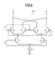
- the first multiplication means, and possibly the second multiplication means advantageously comprise a Gilbert cell whose transistors operate in a linear regime.
- the first and possibly the second measurement means comprise means capable of performing a transformation of the filtered signal in the frequency domain and means for level measurement of the samples corresponding to said frequency component.
- the first and possibly the second generation means are capable of generating a plurality of calibration signals having different calibration frequencies chosen in said initial frequency range and the associated measurement means are suitable. to measure the levels of the corresponding frequency components.
- the device generally comprises a reception channel comprising a low-pass filter arranged downstream of a reception frequency transposition stage, this low-pass filter preferably forms the first and possibly the second filtering means.
- the control means are for example able to activate the first detection means and possibly the second detection means when the device is turned on.
- control means are advantageously able to activate the first detection means and possibly the second detection means during periods of inactivity in transmitting and receiving the device, in particular during changes. temperature detected by the temperature sensor.
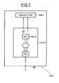
- FIG. 1 illustrates an example of a wireless communication device or WAP transmitter belonging to an uncoordinated communication system such as a wireless local area network (WLAN) or of the WPAN type (Wireless Personal Area). Network).
- WLAN wireless local area network
- WPAN Wireless Personal Area
- Such a WAP wireless device belongs for example to an ultra wide band type communication system based on orthogonal frequency division multiplexing (UWB OFDM) modulation.
- UWB OFDM orthogonal frequency division multiplexing
- the WPAN-MAC protocols have a distributed nature in which there is no coordinating central terminal or base station for assigning accesses to the communication medium.
- a WPAN transmitter has greater flexibility to allocate transmission slots and transmission formats.
- the allocation of communication resources is therefore a distributed process.
- the allocation of a specific time interval in a superframe can be varied from one superframe to another.
- the control entity is the WPAN-MAC layer of the communication terminals. The allocation is based on the required data rate and the type of service to be transmitted. In addition, the available resources are taken into account in the allocation process.
- the MAC layer requests a reservation for a specific time interval or for multiple time slots depending on its constraints. Its constraints can be subdivided into local constraints such as the data rate to be transmitted or received and network level constraints such as the reservation already made for existing time slots.
- An example of a distributed protocol of the WPAN-MAC type is the MBOA-MAC protocol.
- the proposed MBOA standard is based on Ultra Wide Band (UWB) technology and is intended for use in the frequency band between 3.1 and 10.7 GHz.
- the wireless device WAP of FIG. 1 comprises a communication interface of the UWB type based on an OFDM modulation, this interface being referenced MCINT and connected between a UWB application block referenced MBLC and the communication medium (here, the air ).
- the MCINT communication interface comprises a MAC UWB layer synchronized by an MCLK clock signal and connected to a PHY layer as well as to the MBLC application block.
- the MAC and PHY layers are conventional layers and are known per se to those skilled in the art.
- the skilled person can refer to the MBOA PHY layer technical specification, version 1.0, January 2005, as well as the technical specification of MBOA MAC layer, version 0v7, October 2004.
- the MAC layer in particular controls the transmission / reception of the UWB data stream and is software incorporated into a control processor.
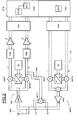
- the communication interface of the WAP device comprises a transmission channel having an analog TX part and a TXN digital part, as well as a reception channel having an analog part. RX and a digital part RXN.
- the transmission channel and the reception channel are of the direct conversion type.
- the two transmission and reception channels are coupled here to the antenna ANT by a duplexer for example.
- the transmission and reception chains operate here in a shared mode (Half Duplex according to an English name usually used), that is to say that the transmission and reception of the signals are not done simultaneously.
- the invention is not limited to an operating mode of the "Half Duplex” type, but can also be applied to an operating mode of the "Full Duplex” type according to a commonly used English name. that is, with simultaneous transmission and reception.
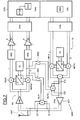
- TX transmission channel conventionally comprises two channels, one in phase I and the other in Q phase quadrature.
- the transmission channel TX comprises a transmission frequency transposition stage comprising here an MXTI mixer arranged on branch I and a mixer MXTQ arranged on the quadrature branch Q.
- the architecture of the WAP device is a differential architecture.
- the invention is not limited to this type of architecture and can also be applied to a single input type architecture (Single Ended according to an English name usually used).
- the two mixers MXTI and MXTQ each receive a transposition signal emitted by a local oscillator OL.
- the transposition signal delivered to the MXTQ mixer is 90 ° out of phase with the transposition signal supplied to the MXTI mixer.
- the output of the two mixers MXTI and MXTQ is connected to an adder whose output is connected to a power amplifier stage PPA.
- the output of the power amplifier PPA is connected to the antenna duplexer.
- the analog part of the reception channel RX conventionally comprises a low noise amplifier LNA whose input is connected to the antenna duplexer and the output of which is connected to a reception frequency transposition stage formed here by two MXRI mixers. and MXRQ respectively arranged on the two branches I and Q of reception.
- the transposition signal received by the mixer MXRQ is delivered by the local oscillator signal OL and shifted by 90 ° with respect to the transposition signal delivered to the mixer MXRI.
- each mixer is connected to a low-pass filter FPB for removing the mixture residues.
- the output of each FPB filter is connected to a CAN digital analog conversion stage via a variable gain amplifier.
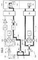
- the WAP device comprises first multiplication means, or multiplier, MLT1 whose two inputs E1 and E2 are connected downstream of the stage of the invention. PPA power amplification.
- the multiplier MLT1 itself multiplies the input signal and outputs this high input signal squared.
- the output of the multiplier MLT1 is connected to one of the branches, here the branch Q, of the receive channel RX, between the corresponding mixer MXRQ and the low-pass filter FPB.
- This connection is made via a switch SW1, formed for example of transistors controllable on their control electrode.
- This switch SW1 is controlled by a control signal emitted by the MAC layer.
- a digital baseband symbol of the UWB-OFDM type is composed of 128 sub-carriers (corresponding conventionally and known to the data, the driver, etc.).
- the transmitted data is generated by calculating the IFFT inverse Fourier transform of 128 baseband digital samples in the frequency domain and completing the result with a number of zero-valued samples.
- the digital portion TXN of the transmission channel comprises a DC encoder, for example a convolutional encoder, receiving data coming from source coding means and delivering a bit stream to means of communication.
- a DC encoder for example a convolutional encoder
- PM which deliver a punched bit stream.
- ILM interleaving means are connected to the output of the puncturing means PM and are followed by Mapping means (Mapping means according to a commonly used English name) which perform a conversion of bits into symbols, according to a schema of FIG. modulation depending on the type of modulation used, for example modulation of the BPSK type or more generally QAM modulation.
- Mapping means Mapping means according to a commonly used English name
- FIG. modulation depending on the type of modulation used, for example modulation of the BPSK type or more generally QAM modulation.
- the successive symbols delivered by the correspondence means MPM are digital symbols in baseband MB-OFDM (OFDM multiband).
- Each symbol is a group containing 128 modulation coefficients respectively associated with 128 sub-carriers to be modulated considering the respective coefficients.
- a group of 128 samples is delivered on the branch I while another corresponding group of 128 samples is delivered on the branch Q.
- the means belonging to the digital stage baseband can be made for example by software in a microprocessor. Another possibility may be to realize at least some of these means, for example the IFFTM means, using specific integrated circuits.
- the time domain symbols delivered by the OFDM IFFTM modulator are then processed in the analog transmit channel after being converted into a digital analog conversion stage CNA.
- the generation means GEN capable of generating the sampling signal can be realized in the present case by means of correspondence MPMA capable of delivering in the domain frequency a reference modulation coefficient associated with a selected subcarrier (a chosen frequency).
- the MPMA means can be made by identical means to the MPM correspondence means.
- These MPMA means may be, in the detection phase, connected to the input of the IFFTM means by a switch also activated by a control signal generated by the MAC control layer.
- a sinusoidal (or cosine) sampling signal referenced SEH i is delivered on the TX transmission channel (FIG. 4).
- the switch SW1 is closed (step 50) and the sampling signal SEH i , having the frequency f i , is generated (step 51).
- the frequency f i of the sampling signal is selected in the baseband frequency range, which in this case ranges from 0 to 264 MHz.
- the transposed sampling signal SEHT i is amplified in the power amplification stage PPA (step 53) and the amplified transposed signal SEHTA i is then squared in the first multiplier MLT1.
- the squared signal SEC1 i has frequency components lying around twice the frequency F of the oscillator as well as frequency components having the frequency f i of the baseband sampling signal and the frequency 2f i .
- Frequency components being around twice the frequency of the local oscillator signal are components that are not troublesome since they are outside the frequency band of the useful signal and will therefore be filtered.
- the frequency components having the frequencies f i and 2f i which result from imperfections of the transmission channel, are, as a function of the value of the frequency f i , in the base band and can therefore interfere with the wanted signals received on the receive channel.
- the squared signal SEC1 i is then filtered (step 55) in the low-pass filter FPB of the reception path so as to eliminate the radio frequency components.
- the filtered signal SECF i is then, after amplification, converted into the digital domain and transformed in the frequency domain by means of FFTM direct Fourier transform (step 56).
- the initial frequency range (baseband) is then scanned by changing the sampling frequency of the generated sampling signal (step 59) and the sequence of the steps just described is repeated.
- baseband the sampling frequency of the generated sampling signal
- the level of the frequency component CF i is representative of the local oscillator leak. In practice, this can be corrected by injecting into the mixer a dc offset voltage for example equal to the opposite of the voltage level measured in the quadratic detector DTC.
- the level of the frequency component C2F i is in turn more representative of an error known to those skilled in the art under the name Anglosaxonne EVM and representative of a deviation from an ideal constellation. This results from a mismatch between the branches I and Q and can also be corrected in a known manner.
- the invention makes it possible to detect imperfections in the transmission channel, regardless of the radio frequency level of the transmitted signal, but particularly for low level signals such as UWB signals for which a detection in the field Radio frequency was difficult to achieve in an integrated manner throughout the radio frequency band of the useful signal.
- the voltages V1 and V2 designate the two inputs of the cell and the differential output formed by the collectors of the transistors M 3 and M 5 on the one hand and M 4 and M 6 on the other hand, delivers the current I out corresponding to the signal SEC1 i .
- the first stage of the Gilbert cell is formed of two other MOS transistors M 1 and M 2 biased by a current source Ib.
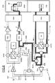
- FIG. 7 differs from that described with reference to FIG. 4 in that there is provided a second multiplier MLT2, of structure similar to that of the first multiplier MLT1, but whose two inputs E10 and E20 are this time connected upstream of the power amplifier PPA.
- the output of the second multiplier MLT2 is also connected upstream of the low-pass filter FPB via a switch SW2 also controllable by the MAC layer.
- a deactivation signal ACT of the power amplifier stage PPA can also be emitted.
- This embodiment is particularly advantageous because it makes it possible to measure more precisely the level of the frequency component having the frequency 2f i . Indeed, the level of this component is lower than the level of the frequency component having the frequency f i . Under these conditions, by deactivating the power amplifier by means of the signal ACT, it is possible to deliver a sampling signal SEH i having a much higher level, which makes it possible, as illustrated in FIG. 8, to obtain a measurement more precise of the frequency component C2F i .
- this second detection phase which is also illustrated in FIG. 9, also makes it possible to measure the level of the frequency component CF i having the frequency f i .
- this second detection phase is analogous to the first detection phase PHD1 1, with the difference that the transposed sampling signal SEHT i is directly squared (step 83) in order to provide the high signal at the same time.
- square SEC2 i square SEC2 i .
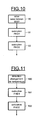
- the first detection phase PHD1 (step 91) as well as the second detection phase PHD2 (step 92) are generally used when the WAP device is turned on (step 90).
- step 100 when the device is equipped with a temperature sensor, and that it detects a temperature change (step 100, FIG. 11), it is then also possible to advantageously perform the two detection phases PHD1 and PHD2 (steps 101 and 102) and during periods of inactivity in transmitting and receiving the device. These periods of inactivity are known to the MAC layer.
Abstract
Description
L'invention concerne les systèmes de communication sans fil, et plus particulièrement la détection d'imperfections de la voie d'émission d'un dispositif radiofréquence sans fil du type à conversion directe.The invention relates to wireless communication systems, and more particularly to the detection of imperfections in the transmission channel of a direct conversion type wireless radio frequency device.
L'invention s'applique avantageusement mais non limitativement aux dispositifs opérant selon la norme à bande ultra large (UWB : Ultra Wide Band) basée sur un multiplexage multibandes par répartition orthogonale de fréquences (Multiband OFDM : Multiband Orthogonal Frequency-Division Multiplexing). Une telle norme est connue sous la dénomination MBOA (Multiband OFDM Alliance).The invention applies advantageously but not exclusively to devices operating according to the Ultra Wide Band (UWB) standard based on an orthogonal frequency division multiband multiplexing (Multiband Orthogonal Frequency Multiplexing OFDM). Such a standard is known as MBOA (Multiband OFDM Alliance).
Le multiplexage par répartition orthogonale de fréquences (OFDM) est un procédé de modulation numérique dans lequel un signal est divisé en plusieurs canaux à bande étroite (sous-porteuses) ayant des fréquences différentes.Orthogonal frequency division multiplexing (OFDM) is a method of digital modulation in which a signal is divided into several narrow-band (subcarrier) channels having different frequencies.
Un récepteur à conversion directe, encore appelé récepteur à fréquence intermédiaire nulle (récepteur « ZIF ») possède une architecture homodyne et convertit (transpose) le signal reçu, par exemple un signal radiofréquence UWB OFDM, directement en bande de base, c'est-à-dire directement autour de la fréquence 0 Hz.A direct conversion receiver, also called a zero intermediate frequency receiver ("ZIF" receiver) has a homodyne architecture and converts (transposes) the received signal, for example a UWB OFDM radiofrequency signal, directly into a baseband, ie ie directly around the frequency 0 Hz.
De même, un émetteur à conversion directe convertit (transpose) le signal en bande de base directement en un signal radiofréquence.Similarly, a direct conversion transmitter converts (transposes) the baseband signal directly into a radio frequency signal.
Les intérêts d'une telle architecture à structure homodyne sont les éliminations du traitement de l'image et des filtres de fréquences intermédiaires. De ce fait, un tel dispositif (émetteur/récepteur) est plus facile à intégrer qu'un dispositif hétérodyne dans lequel la conversion descendante correspondante en bande de base et la conversion montante dans le domaine radiofréquence s'effectuent par le biais d'une ou de plusieurs transpositions intermédiaires à des fréquences intermédiaires.The interests of such a homodyne structure architecture are the eliminations of image processing and intermediate frequency filters. As a result, such a device (transmitter / receiver) is easier to integrate than a heterodyne device in which the corresponding baseband downconversion and upconversion in the radio frequency domain are performed by through one or more intermediate transpositions at intermediate frequencies.
Cependant, de tels dispositifs à conversion directe, en particulier les émetteurs, sont sujets à des imperfections ayant des effets sur la qualité du spectre du signal transmis. Ces imperfections sont en particulier dues à des puissances parasites transmises au niveau de l'antenne en raison des fuites d'oscillateur local et à une fréquence image non désirée au niveau de l'antenne provoquée par un désappariement en phase et/ou en gain des deux voies I et Q de la chaîne d'émission.However, such direct conversion devices, in particular transmitters, are subject to imperfections having effects on the quality of the spectrum of the transmitted signal. These imperfections are in particular due to parasitic powers transmitted at the antenna due to local oscillator leakage and at an unwanted image frequency at the antenna caused by phase mismatch and / or gain in the antenna. two I and Q channels of the transmission chain.
Il est important de pouvoir détecter ces imperfections de la voie d'émission, notamment en termes de puissances parasites émises au niveau de l'antenne.It is important to be able to detect these imperfections of the transmission channel, especially in terms of parasitic powers emitted at the antenna.
Traditionnellement, un détecteur radiofréquence est inséré à la sortie de l'étage amplificateur de puissance de la voie d'émission pour mesurer la puissance radiofréquence et l'enveloppe du signal émis. Le signal ainsi mesuré est numérisé et envoyé à l'étage numérique de traitement en bande de base qui traite les données correspondantes et effectue les corrections nécessaires.Traditionally, a radio frequency detector is inserted at the output of the power amplifier stage of the transmission channel for measuring the radiofrequency power and the envelope of the transmitted signal. The signal thus measured is digitized and sent to the digital baseband processing stage which processes the corresponding data and makes the necessary corrections.
Or, lorsque les normes imposent un faible niveau de puissance maximum à l'émission (incluant la puissance du signal utile et la puissance parasite résultant des imperfections de la voie d'émission), comme c'est le cas pour la norme MBOA (selon laquelle la puissance ne doit pas dépasser -41 dBm par MHz, c'est-à-dire -14 dBm pour une bande de 528 MHz), les détecteurs radiofréquence classiques, comme par exemple les détecteurs de niveau quadratique (détecteurs RMS : Root Mean Square) réalisés sous forme intégrée, ne permettent pas de réaliser cette détection de puissance dans toute la bande radiofréquence du signal, en particulier lorsque le signal radiofréquence est faible.However, when the standards impose a low maximum power level on transmission (including the power of the wanted signal and the parasitic power resulting from the imperfections of the transmission channel), as is the case for the MBOA standard (according to which power should not exceed -41 dBm per MHz, ie -14 dBm for a band of 528 MHz), conventional radio frequency detectors, such as quadratic level detectors (RMS detectors: Root Mean Square) realized in integrated form, do not make it possible to realize this detection of power in all the radiofrequency band of the signal, in particular when the radiofrequency signal is weak.
L'invention vise à apporter une solution à ce problème.The invention aims to provide a solution to this problem.
Selon un aspect de l'invention, il est proposé un procédé de détection d'imperfections de la voie d'émission d'un dispositif radiofréquence du type à conversion directe comportant un étage de transposition de fréquence d'émission apte à transposer un signal en bande de base dont la fréquence se situe dans une plage initiale de fréquences, (par exemple la plage de 0 à 264 MHz) en un signal radiofréquence.According to one aspect of the invention, there is provided a method for detecting imperfections in the transmission channel of a direct conversion type radiofrequency device comprising a stage of transmission frequency transposition adapted to transpose a baseband signal whose frequency is within an initial range of frequencies, (for example the range of 0 to 264 MHz) into a radio frequency signal.
Le procédé comprend au moins une première phase de détection dans laquelle on génère un signal d'étalonnage en bande de base ayant une fréquence d'étalonnage choisie dans ladite plage initiale, on multiplie par lui-même (c'est-à-dire que l'on élève au carré) un signal d'étalonnage transposé issu dudit signal d'étalonnage en bande de base, ce signal d'étalonnage transposé étant prélevé en aval de l'étage de transposition de fréquence d'émission de façon à obtenir un signal transposé élevé au carré, on filtre le signal transposé élevé au carré de façon à en éliminer les composantes radiofréquence, et on mesure au moins le niveau de la composante fréquentielle du signal filtré ayant ladite fréquence d'étalonnage.The method comprises at least a first detection phase in which a baseband calibration signal is generated having a calibration frequency selected from said initial range, multiplying by itself (i.e. squaring a transposed calibration signal from said baseband calibration signal, which transposed calibration signal is taken downstream of the transmit frequency transposition stage so as to obtain a transposed calibration signal from said baseband calibration signal; a transposed signal squared, the transposed signal squared is filtered so as to eliminate the radiofrequency components, and at least the level of the frequency component of the filtered signal having said calibration frequency is measured.
Ainsi, selon l'invention, l'élévation au carré du signal transposé en combinaison avec un filtrage du signal de façon à éliminer les composantes radiofréquence, permet de mesurer de façon très simple le niveau de la composante fréquentielle du signal filtré qui a la fréquence d'étalonnage, ce niveau de cette composante fréquentielle étant représentatif de certaines imperfections de la voie d'émission, en particulier des fuites d'oscillateur local.Thus, according to the invention, the squaring of the transposed signal in combination with a filtering of the signal so as to eliminate the radiofrequency components makes it possible to measure in a very simple manner the level of the frequency component of the filtered signal which has the frequency calibration, this level of this frequency component being representative of certain imperfections of the transmission channel, in particular local oscillator leaks.
Et, une telle détection, bien qu'elle puisse s'appliquer à tout signal radiofréquence quel que soit son niveau d'émission, est particulièrement bien adaptée aux signaux radiofréquence ayant un faible niveau d'émission admissible, comme c'est le cas en particulier pour certains signaux UWB.And, such a detection, although it can be applied to any radiofrequency signal regardless of its emission level, is particularly well adapted to radiofrequency signals having a low permissible emission level, as is the case in particular for certain UWB signals.
Il est en outre avantageux que la première phase de détection comporte en outre une mesure de niveau de la composante fréquentielle du signal filtré ayant le double de ladite fréquence d'étalonnage.It is furthermore advantageous that the first detection phase further includes a measurement of the frequency component level of the filtered signal having twice said calibration frequency.
Ceci permet également de détecter un autre type d'imperfection de la voie d'émission telle qu'une déviation par rapport à la constellation idéale provoquée en particulier par les désappariements en gain et/ou en phase des voies I et Q de la voie d'émission.This also makes it possible to detect another type of imperfection of the transmission path such as a deviation from the ideal constellation caused in particular by the mismatches in gain and / or phase of channels I and Q of the transmission channel.
La voie d'émission comporte généralement un étage amplificateur de puissance disposé en aval de l'étage de transposition de fréquence.The transmission path generally comprises a power amplifier stage arranged downstream of the frequency transposition stage.
Selon un mode de mise en oeuvre, on peut prélever le signal d'échantillonnage transposé, en aval de l'étage amplificateur de puissance. Ceci permet de manière avantageuse, de prendre en compte également directement les influences de l'étage amplificateur de puissance. Mais, il serait également possible de prélever le signal d'échantillonnage en amont de l'étage amplificateur de puissance en tenant compte des gains théoriques de l'étage amplificateur de puissance.According to one embodiment, it is possible to take the transposed sampling signal downstream of the power amplifier stage. This advantageously makes it possible to also directly take into account the influences of the power amplifier stage. However, it would also be possible to take the sampling signal upstream of the power amplifier stage, taking into account the theoretical gains of the power amplifier stage.
Cela étant, prélever le signal d'échantillonnage transposé en amont de l'étage amplificateur de puissance permet lorsque l'étage amplificateur de puissance est désactivé, d'avoir une mesure plus précise du niveau de la composante fréquentielle du signal filtré ayant le double de la fréquence d'échantillonnage car une telle mesure nécessite d'émettre le signal d'échantillonnage en bande de base avec un plus fort niveau que celui nécessaire pour la mesure de la composante fréquentielle ayant simplement la fréquence d'étalonnage.However, taking the sampling signal transposed upstream of the power amplifier stage makes it possible, when the power amplifier stage is deactivated, to have a more precise measurement of the level of the frequency component of the filtered signal having twice the power. the sampling frequency because such a measurement requires the baseband sampling signal to be transmitted at a higher level than that required for the measurement of the frequency component having simply the calibration frequency.
Cela étant, il est tout à fait possible de façon à mesurer très précisément le niveau de la composante fréquentielle à la fréquence d'étalonnage f1 et le niveau de la composante fréquentielle à la fréquence 2f1, lorsque le procédé comporte en outre une deuxième phase de détection, effectuée à un instant différent de la première phase de détection.That being so, it is quite possible to measure very precisely the level of the frequency component at the calibration frequency f1 and the level of the frequency component at the frequency 2f1, when the method also comprises a second phase of detection, performed at a different time of the first detection phase.
Au cours de cette deuxième phase de détection, on désactive l'étage amplificateur de puissance, on génère un signal d'étalonnage en bande de base ayant une fréquence d'étalonnage choisie dans la plage initiale, on prélève le signal d'échantillonnage transposé en amont de l'étage amplificateur de puissance, on le multiplie par lui-même et on filtre le signal transposé élevé au carré de façon à en éliminer les composantes radiofréquences et on mesure au moins le niveau de la composante fréquentielle du signal filtré ayant le double de ladite fréquence d'étalonnage.During this second detection phase, the power amplifier stage is deactivated, a baseband calibration signal is generated which has a calibration frequency selected from the initial range, and the sampled sampling signal is taken into account. upstream of the power amplifier stage, it is multiplied by itself and the transposed high signal squared to remove the radiofrequency components and is measured at least the level of the frequency component of the filtered signal having twice said calibration frequency.
En d'autres termes, bien qu'il soit possible de mesurer dans chacune des phases de détection, à la fois le niveau de la composante f1 et le niveau de la composante 2f1, on utilisera préférentiellement la première phase de détection, c'est-à-dire l'élévation au carré du signal prélevé en aval de l'étage d'amplificateur de puissance pour mesurer le niveau de la composante f1 du signal filtré, et on utilisera préférentiellement la deuxième phase de détection, c'est-à-dire celle où l'on élève au carré le signal prélevé en amont de l'étage amplificateur de puissance, pour mesurer le niveau de la composante fréquentielle 2f1.In other words, although it is possible to measure in each of the detection phases, both the level of the component f1 and the level of the component 2f1, the first phase of detection will preferably be used; i.e. squaring the signal taken downstream of the power amplifier stage to measure the level of the component f1 of the filtered signal, and the second phase of detection will preferably be used, ie ie the one where the signal taken upstream of the power amplifier stage is squared up to measure the level of the frequency component 2f1.
Les deux phases de détection sont en fait analogues et diffèrent simplement par l'endroit où l'on prélève le signal transposé à élever au carré. En outre, pour la deuxième phase de détection, on désactive l'étage amplificateur de puissance. Enfin, on n'effectue pas ces deux phases de détection en même temps.The two phases of detection are in fact analogous and differ only in the place where the transposed signal is taken to square. In addition, for the second detection phase, the power amplifier stage is deactivated. Finally, these two detection phases are not carried out at the same time.
Selon un mode de mise en oeuvre de l'invention, la mesure du niveau d'une composante fréquentielle du signal filtré comporte une transformée du signal filtré dans le domaine fréquentiel, par exemple par une transformée de Fourier, et une mesure de niveau des échantillons correspondant à ladite composante fréquentielle, par exemple en utilisant une détection quadratique (détection RMS), ce qui est aisément possible puisqu'on se situe dans le domaine fréquentiel de la bande de base.According to an embodiment of the invention, the measurement of the level of a frequency component of the filtered signal comprises a transformation of the filtered signal in the frequency domain, for example by a Fourier transform, and a level measurement of the samples. corresponding to said frequency component, for example using a quadratic detection (RMS detection), which is easily possible since it is in the frequency domain of the baseband.
De façon à couvrir au moins en partie toute la bande de base, on peut générer, dans chaque phase de détection, plusieurs signaux d'étalonnage ayant des fréquences d'étalonnage différentes choisies dans la plage de fréquences initiale (0-264 MHz par exemple) et on mesure alors le niveau des composantes fréquentielles correspondantes.In order to cover at least part of the entire baseband, several calibration signals can be generated in each detection phase having different calibration frequencies chosen in the initial frequency range (0-264 MHz for example). ) and the level of the corresponding frequency components is then measured.
On choisira de préférence un signal d'étalonnage ayant une fréquence pure en étant au maximum exempt d'harmonique. On pourra par exemple utiliser un signal sinusoïdal.Preferably, a calibration signal having a pure frequency will be chosen while being at most harmonic-free. For example, a sinusoidal signal may be used.
Le dispositif radiofréquence comporte également généralement une voie de réception comportant un filtre passe-bas disposé en aval d'un étage de transposition de fréquence de réception. On utilise avantageusement ce filtre passe-bas pour filtrer le signal transposé élevé au carré et prélevé sur la voie d'émission.The radio frequency device also generally comprises a reception channel comprising a low-pass filter arranged downstream of a reception frequency transposition stage. This low-pass filter is advantageously used to filter the transposed high signal squared and taken from the transmission channel.
On effectue avantageusement chaque phase de détection à la mise sous tension du dispositif.Advantageously, each detection phase is performed when the device is powered up.
Cela étant, on peut effectuer chaque phase de détection au cours de périodes d'inactivité en émission et réception du dispositif, en particulier lors de changements de température.However, each detection phase can be carried out during periods of inactivity in transmitting and receiving the device, in particular during temperature changes.
Bien entendu, dans tout ce qui vient d'être mentionné, le mot « chaque » affecté à la phase de détection, concerne l'une et/ou l'autre des phases de détection.Of course, in all that has just been mentioned, the word "each" assigned to the detection phase relates to one and / or the other of the detection phases.
Selon un autre aspect de l'invention, il est également proposé un dispositif radiofréquence du type à conversion directe, comportant un étage de transposition de fréquence d'émission apte à transposer un signal en bande de base dont la fréquence se situe dans une plage initiale de fréquences en un signal radiofréquence.According to another aspect of the invention, it is also proposed a radio frequency device of the direct conversion type, comprising a transmission frequency transposition stage adapted to transpose a baseband signal whose frequency is in an initial range frequency into a radio frequency signal.
Selon une caractéristique générale de cet autre aspect de l'invention, le dispositif comprend au moins des premiers moyens activables de détection comportant
des premiers moyens de génération apte à générer un signal d'étalonnage en bande de base ayant une fréquence d'étalonnage choisie dans ladite plage initiale,
des premiers moyens de multiplication possédant ses deux entrées connectées en aval de l'étage de transposition de fréquence d'émission de façon à délivrer un signal transposé élevé au carré issu dudit signal d'étalonnage en bande de base,
des premiers moyens de filtrage aptes à filtrer le signal transposé élevé au carré de façon à en éliminer les composantes radiofréquences, et
des premiers moyens de mesure aptes à mesurer au moins le niveau de la composante fréquentielle du signal filtré ayant ladite fréquence d'étalonnage.According to a general characteristic of this other aspect of the invention, the device comprises at least first activatable detection means comprising
first generation means adapted to generate a baseband calibration signal having a calibration frequency selected from said initial range,
first multiplier means having its two inputs connected downstream of the transmit frequency transposition stage so as to output a squared-up transposed signal from said baseband calibration signal,
first filtering means adapted to filter the transposed signal squared so as to eliminate the radiofrequency components, and
first measuring means capable of measuring at least the level of the frequency component of the filtered signal having said calibration frequency.
Selon un mode de réalisation, les premiers moyens de mesure sont aptes en outre à mesurer le niveau de la composante fréquentielle du signal filtré ayant le double de ladite fréquence d'étalonnage.According to one embodiment, the first measurement means are further able to measure the level of the frequency component of the filtered signal having twice said calibration frequency.
Selon un mode de réalisation de l'invention dans lequel la voie d'émission comporte un étage amplificateur de puissance disposé en aval de l'étage de transposition de fréquence d'émission, les deux entrées des premiers moyens de multiplication sont connectées en aval de l'étage amplificateur de puissance.According to one embodiment of the invention in which the transmission channel comprises a power amplifier stage disposed downstream of the transmission frequency transposition stage, the two inputs of the first multiplication means are connected downstream of the power amplifier stage.
Selon un autre mode de mise en oeuvre de l'invention, les deux entrées des premiers moyens de multiplication sont connectées en amont de l'étage amplificateur de puissance, et le dispositif comporte en outre des moyens de commande aptes à désactiver l'étage amplificateur de puissance pour activer les premiers moyens de détection.According to another embodiment of the invention, the two inputs of the first multiplication means are connected upstream of the power amplifier stage, and the device further comprises control means able to deactivate the amplifier stage. of power to activate the first detection means.
Selon un mode de réalisation de l'invention, le dispositif comporte en outre des deuxièmes moyens activables de détection, comportant
des deuxièmes moyens de génération apte à générer un signal d'étalonnage en bande de base ayant une fréquence d'étalonnage choisie dans ladite plage initiale,
des deuxièmes moyens de multiplication possédant ses deux entrées connectées en aval de l'étage de transposition de fréquence d'émission et en amont de l'étage d'amplification de puissance de façon à délivrer un signal transposé élevé au carré issu dudit signal d'étalonnage en bande de base,
des deuxièmes moyens de filtrage aptes à filtrer le signal transposé élevé au carré de façon à en éliminer les composantes radiofréquences, et
des deuxièmes moyens de mesure aptes à mesurer au moins le niveau de la composante fréquentielle du signal filtré ayant le double de ladite fréquence d'étalonnage ;
le dispositif comporte en outre des moyens de commande aptes à désactiver l'étage amplificateur de puissance et les premiers moyens de détection pour activer les deuxièmes moyens de détection.According to one embodiment of the invention, the device further comprises second activatable detection means, comprising
second generation means adapted to generate a baseband calibration signal having a calibration frequency selected from said initial range,
second multiplication means having its two inputs connected downstream of the transmission frequency transposition stage and upstream of the power amplification stage so as to deliver a high-square transposed signal derived from said signal of baseband calibration,
second filtering means capable of filtering the transposed signal squared to remove the radiofrequency components, and
second measuring means adapted to measure at least the level of the frequency component of the filtered signal having twice said calibration frequency;
the device further comprises control means adapted to deactivate the power amplifier stage and the first detection means for activating the second detection means.
De préférence, les premiers et deuxièmes moyens de génération sont des moyens communs, les premiers et deuxièmes de filtrage sont des moyens communs et les premiers et deuxièmes moyens de mesure sont des moyens communs.Preferably, the first and second generation means are common means, the first and second filtering means are common and the first and second measuring means are common means.
De façon à ne pas créer d'harmonique supplémentaire, les premiers moyens de multiplication, et éventuellement les deuxièmes moyens de multiplication comportent avantageusement une cellule de Gilbert dont les transistors fonctionnent en régime linéaire.In order not to create additional harmonic, the first multiplication means, and possibly the second multiplication means advantageously comprise a Gilbert cell whose transistors operate in a linear regime.
Selon un mode de réalisation de l'invention, les premiers et éventuellement les deuxièmes moyens de mesure comportent des moyens aptes à effectuer une transformée du signal filtré dans le domaine fréquentiel et des moyens de mesure de niveau des échantillons correspondant à ladite composante fréquentielle.According to one embodiment of the invention, the first and possibly the second measurement means comprise means capable of performing a transformation of the filtered signal in the frequency domain and means for level measurement of the samples corresponding to said frequency component.
Selon un mode de réalisation de l'invention, les premiers et éventuellement les deuxièmes moyens de génération sont aptes à générer plusieurs signaux d'étalonnage ayant des fréquences d'étalonnage différentes choisies dans ladite plage de fréquences initiale et les moyens de mesure associés sont aptes à mesurer les niveaux des composantes fréquentielles correspondantes.According to one embodiment of the invention, the first and possibly the second generation means are capable of generating a plurality of calibration signals having different calibration frequencies chosen in said initial frequency range and the associated measurement means are suitable. to measure the levels of the corresponding frequency components.
Le dispositif comprenant généralement une voie de réception comportant un filtre passe-bas disposé en aval d'un étage de transposition de fréquences de réception, ce filtre passe-bas forme de préférence les premiers et éventuellement les deuxièmes moyens de filtrage.Since the device generally comprises a reception channel comprising a low-pass filter arranged downstream of a reception frequency transposition stage, this low-pass filter preferably forms the first and possibly the second filtering means.
Les moyens de commande sont par exemple aptes à activer les premiers moyens de détection et éventuellement les deuxièmes moyens de détection à la mise sous tension du dispositif.The control means are for example able to activate the first detection means and possibly the second detection means when the device is turned on.
Lorsque le dispositif comporte un capteur de température, les moyens de commande sont avantageusement aptes à activer les premiers moyens de détection et éventuellement les deuxièmes moyens de détection au cours de périodes d'inactivité en émission et en réception du dispositif, en particulier lors de changements de température détectés par le capteur de température.When the device comprises a temperature sensor, the control means are advantageously able to activate the first detection means and possibly the second detection means during periods of inactivity in transmitting and receiving the device, in particular during changes. temperature detected by the temperature sensor.
D'autres avantage et caractéristiques de l'invention apparaîtront à l'examen de la description détaillée de modes de réalisation et de mise en oeuvre, nullement limitatifs, et des dessins annexés sur lesquels :
- la figure 1 illustre de façon schématique la structure de protocole interne d'un émetteur/récepteur sans fil selon un mode de réalisation de l'invention,
- les figures 2 et 3 illustrent plus en détail toujours de façon schématique, des exemples de structures d'un dispositif de la figure 1 ,
- les figures 4 et 5 illustrent de façon schématique un premier mode de mise en oeuvre du procédé selon l'invention,
- la figure 6 illustre schématiquement un mode de réalisation d'un multiplieur utilisé dans l'invention,
- la figure 7 illustre schématiquement et plus en détail un second mode de réalisation d'un dispositif selon l'invention,
- les figures 8 et 9 illustrent de façon schématique un deuxième mode de mise en oeuvre du procédé selon l'invention, et,
- les figures 10 et 11 illustrent de façon schématique différents cas possibles de mise en oeuvre des phases de détection du procédé selon l'invention.
- FIG. 1 schematically illustrates the internal protocol structure of a wireless transceiver according to one embodiment of the invention,
- FIGS. 2 and 3 show in more detail, in a schematic manner, examples of structures of a device of FIG. 1,
- FIGS. 4 and 5 schematically illustrate a first mode of implementation of the method according to the invention,
- FIG. 6 schematically illustrates an embodiment of a multiplier used in the invention,
- FIG. 7 diagrammatically and in more detail a second embodiment of a device according to the invention,
- Figures 8 and 9 schematically illustrate a second embodiment of the method according to the invention, and
- Figures 10 and 11 illustrate schematically different possible cases of implementation of the detection phases of the method according to the invention.
La figure 1 illustre un exemple d'un dispositif de communication sans fil ou transmetteur WAP appartenant à un système de communication non coordonné tel qu'un réseau local sans fil du type WLAN (Wireless Local Area Network) ou du type WPAN (Wireless Personal Area Network).FIG. 1 illustrates an example of a wireless communication device or WAP transmitter belonging to an uncoordinated communication system such as a wireless local area network (WLAN) or of the WPAN type (Wireless Personal Area). Network).
Un tel dispositif sans fil WAP appartient par exemple à un système de communication du type à bande ultra large basé sur une modulation à multiplexage par répartition orthogonale de fréquences (UWB OFDM).Such a WAP wireless device belongs for example to an ultra wide band type communication system based on orthogonal frequency division multiplexing (UWB OFDM) modulation.
Les protocoles WPAN-MAC ont une nature distribuée dans laquelle il n'y a aucun terminal central coordinateur ou station de base pour assigner les accès au milieu de communication. Ainsi, par opposition à un téléphone mobile cellulaire par exemple, un transmetteur WPAN a une plus grande flexibilité pour allouer les intervalles de transmission et les formats de transmission. L'allocation des ressources de communication est donc un processus distribué. L'allocation d'un intervalle de temps spécifique dans une supertrame peut être modifiée d'une supertrame à une autre. L'entité de commande est la couche WPAN-MAC des terminaux de communication. L'allocation est basée sur le débit de données requis et sur le type de service à transmettre. En outre, les ressources disponibles sont prises en compte dans le processus d'allocation. La couche MAC demande une réservation pour un intervalle de temps spécifique ou pour plusieurs intervalles de temps en fonction de ses contraintes. Ses contraintes peuvent être subdivisées en des contraintes locales telles que le débit de données à transmettre ou à recevoir et en des contraintes au niveau réseau telles que la réservation déjà effectuée pour des intervalles de temps existants.The WPAN-MAC protocols have a distributed nature in which there is no coordinating central terminal or base station for assigning accesses to the communication medium. Thus, as opposed to a cellular mobile phone for example, a WPAN transmitter has greater flexibility to allocate transmission slots and transmission formats. The allocation of communication resources is therefore a distributed process. The allocation of a specific time interval in a superframe can be varied from one superframe to another. The control entity is the WPAN-MAC layer of the communication terminals. The allocation is based on the required data rate and the type of service to be transmitted. In addition, the available resources are taken into account in the allocation process. The MAC layer requests a reservation for a specific time interval or for multiple time slots depending on its constraints. Its constraints can be subdivided into local constraints such as the data rate to be transmitted or received and network level constraints such as the reservation already made for existing time slots.
Un exemple de protocole distribué du type WPAN-MAC est le protocole MBOA-MAC.An example of a distributed protocol of the WPAN-MAC type is the MBOA-MAC protocol.
Le projet de norme MBOA est basé sur la technologie à Bande Ultra Large (UWB) et est prévu pour être utilisé dans la bande fréquentielle s'étendant entre 3,1 et 10,7 GHz. Des premières réalisations utilisant cette norme, fonctionnent dans la plage fréquentielle 3,1-5 GHz.The proposed MBOA standard is based on Ultra Wide Band (UWB) technology and is intended for use in the frequency band between 3.1 and 10.7 GHz. First implementations using this standard, operate in the frequency range 3.1-5 GHz.
Le dispositif sans fil WAP de la figure 1 comprend une interface de communication du type UWB basée sur une modulation OFDM, cette interface étant référencée MCINT et connectée entre un bloc d'application UWB référencé MBLC et le milieu de communication (ici, l'air).The wireless device WAP of FIG. 1 comprises a communication interface of the UWB type based on an OFDM modulation, this interface being referenced MCINT and connected between a UWB application block referenced MBLC and the communication medium (here, the air ).
L'interface de communication MCINT comprend une couche UWB MAC synchronisée par un signal d'horloge MCLK et connectée à une couche PHY ainsi qu'au bloc d'application MBLC.The MCINT communication interface comprises a MAC UWB layer synchronized by an MCLK clock signal and connected to a PHY layer as well as to the MBLC application block.
Les couches MAC et PHY sont des couches classiques et connues en soi par l'homme du métier. Pour plus de détails concernant les couches MAC et PHY de l'interface de communication MCINT, l'homme du métier peut se référer à la spécification technique de la couche MBOA PHY, version 1.0, janvier 2005, ainsi qu'à la spécification technique de la couche MBOA MAC, version 0v7, octobre 2004.The MAC and PHY layers are conventional layers and are known per se to those skilled in the art. For more details on the MCINT and PHY layers of the MCINT communication interface, the skilled person can refer to the MBOA PHY layer technical specification, version 1.0, January 2005, as well as the technical specification of MBOA MAC layer, version 0v7, October 2004.
La couche MAC contrôle en particulier l'émission/réception du flux de données UWB et est incorporée par logiciel dans un processeur de commande.The MAC layer in particular controls the transmission / reception of the UWB data stream and is software incorporated into a control processor.
Si l'on se réfère maintenant plus particulièrement à la figure 2, l'interface de communication du dispositif WAP comprend une voie d'émission ayant une partie analogique TX et une partie numérique TXN, ainsi qu'une voie de réception ayant une partie analogique RX et une partie numérique RXN.Referring now more particularly to FIG. 2, the communication interface of the WAP device comprises a transmission channel having an analog TX part and a TXN digital part, as well as a reception channel having an analog part. RX and a digital part RXN.
La voie d'émission et la voie de réception sont du type à conversion directe.The transmission channel and the reception channel are of the direct conversion type.
Les deux voies d'émission et de réception sont couplées ici à l'antenne ANT par un duplexeur par exemple.The two transmission and reception channels are coupled here to the antenna ANT by a duplexer for example.
Les chaînes d'émission et de réception fonctionnent ici dans un mode partagé (Half Duplex selon une dénomination anglo-saxonne habituellement utilisée) c'est-à-dire que la transmission et la réception des signaux ne se font pas de façon simultanée.The transmission and reception chains operate here in a shared mode (Half Duplex according to an English name usually used), that is to say that the transmission and reception of the signals are not done simultaneously.
Cela étant, l'invention n'est pas limitée à un mode de fonctionnement du type « Half Duplex » mais peut également s'appliquer à un mode de fonctionnement du type « Full Duplex »selon une dénomination anglo-saxonne habituellement utilisée, c'est-à-dire avec une transmission et une réception simultanées.That being so, the invention is not limited to an operating mode of the "Half Duplex" type, but can also be applied to an operating mode of the "Full Duplex" type according to a commonly used English name. that is, with simultaneous transmission and reception.
La partie analogique de la voie d'émission TX comporte de façon classique deux voies, l'une en phase I et l'autre en quadrature de phase Q.The analog part of TX transmission channel conventionally comprises two channels, one in phase I and the other in Q phase quadrature.
La voie d'émission TX comporte un étage de transposition de fréquence d'émission comportant ici un mélangeur MXTI disposé sur la branche I et un mélangeur MXTQ disposé sur la branche en quadrature Q.The transmission channel TX comprises a transmission frequency transposition stage comprising here an MXTI mixer arranged on branch I and a mixer MXTQ arranged on the quadrature branch Q.
Il convient de noter ici que l'architecture du dispositif WAP est une architecture différentielle. Naturellement, l'invention n'est pas limitée à ce type d'architecture et peut également s'appliquer à une architecture du type à entrée unique (Single Ended selon une dénomination anglo-saxonne habituellement utilisée).It should be noted here that the architecture of the WAP device is a differential architecture. Naturally, the invention is not limited to this type of architecture and can also be applied to a single input type architecture (Single Ended according to an English name usually used).
Les deux mélangeurs MXTI et MXTQ reçoivent chacun un signal de transposition émis par un oscillateur local OL. Cela étant, le signal de transposition délivré au mélangeur MXTQ est déphasé de 90° par rapport au signal de transposition délivré au mélangeur MXTI.The two mixers MXTI and MXTQ each receive a transposition signal emitted by a local oscillator OL. However, the transposition signal delivered to the MXTQ mixer is 90 ° out of phase with the transposition signal supplied to the MXTI mixer.
La sortie des deux mélangeurs MXTI et MXTQ est reliée à un additionneur dont la sortie est connectée à un étage d'amplification de puissance PPA.The output of the two mixers MXTI and MXTQ is connected to an adder whose output is connected to a power amplifier stage PPA.
La sortie de l'amplificateur de puissance PPA est reliée au duplexeur d'antenne.The output of the power amplifier PPA is connected to the antenna duplexer.
La partie analogique de la voie de réception RX comporte de façon classique un amplificateur faible bruit LNA dont l'entrée est connectée au duplexeur d'antenne et dont la sortie est connectée à un étage de transposition de fréquence de réception formé ici de deux mélangeurs MXRI et MXRQ respectivement disposés sur les deux branches I et Q de réception.The analog part of the reception channel RX conventionally comprises a low noise amplifier LNA whose input is connected to the antenna duplexer and the output of which is connected to a reception frequency transposition stage formed here by two MXRI mixers. and MXRQ respectively arranged on the two branches I and Q of reception.
Là encore, le signal de transposition reçu par le mélangeur MXRQ est délivré par le signal d'oscillateur local OL et déphasé de 90° par rapport au signal de transposition délivré au mélangeur MXRI.Here again, the transposition signal received by the mixer MXRQ is delivered by the local oscillator signal OL and shifted by 90 ° with respect to the transposition signal delivered to the mixer MXRI.
La sortie de chaque mélangeur est reliée à un filtre passe-bas FPB destiné à éliminer les résidus de mélanges. La sortie de chaque filtre FPB est connectée à un étage de conversion analogique numérique CAN par l'intermédiaire d'un amplificateur à gain variable.The output of each mixer is connected to a low-pass filter FPB for removing the mixture residues. The output of each FPB filter is connected to a CAN digital analog conversion stage via a variable gain amplifier.
Outre les moyens qui viennent d'être décrits, le dispositif WAP selon ce mode de réalisation de l'invention comporte des premiers moyens de multiplication, ou multiplieur, MLT1 dont les deux entrées E1 et E2 sont connectées en aval de l'étage d'amplification de puissance PPA.In addition to the means that have just been described, the WAP device according to this embodiment of the invention comprises first multiplication means, or multiplier, MLT1 whose two inputs E1 and E2 are connected downstream of the stage of the invention. PPA power amplification.
On peut d'ores et déjà observer ici que de par sa configuration, le multiplieur MLT1 multiplie par lui-même le signal en entrée et délivre en sortie ce signal d'entrée élevé au carré.It can already be observed here that by its configuration, the multiplier MLT1 itself multiplies the input signal and outputs this high input signal squared.
La sortie du multiplieur MLT1 est connectée sur l'une des branches, ici la branche Q, de la voie de réception RX, entre le mélangeur correspondant MXRQ et le filtre passe-bas FPB. Cette connexion s'effectue par l'intermédiaire d'un interrupteur SW1, formé par exemple de transistors commandables sur leur électrode de commande. Cet interrupteur SW1 est commandé par un signal de commande émis par la couche MAC.The output of the multiplier MLT1 is connected to one of the branches, here the branch Q, of the receive channel RX, between the corresponding mixer MXRQ and the low-pass filter FPB. This connection is made via a switch SW1, formed for example of transistors controllable on their control electrode. This switch SW1 is controlled by a control signal emitted by the MAC layer.
Bien entendu, il aurait été tout à fait possible de connecter la sortie du multiplieur MLT1 sur l'autre branche, ici la branche I, de la voie de réception.Of course, it would have been quite possible to connect the output of the multiplier MLT1 to the other branch, here the branch I, of the reception channel.
De façon à pouvoir mettre en oeuvre une première phase de détection selon l'invention, ainsi qu'il sera explicité plus en détail ci-après, il est également prévu dans la partie numérique TXN de la voie d'émission, contenue dans l'étage numérique de traitement ETN (processeur en bande de base) des moyens de génération d'un signal d'étalonnage en bande de base, référencés GEN.In order to be able to implement a first detection phase according to the invention, as will be explained in more detail below, it is also provided in the digital part TXN of the transmission channel, contained in the digital processing stage ETN (baseband processor) means for generating a baseband calibration signal, referenced GEN.
De façon classique, un symbole numérique en bande de base du type UWB-OFDM est composé de 128 sous-porteuses (correspondant de façon classique et connue aux données, au pilote, etc.). Les données transmises sont générées en calculant la transformée de Fourier inverse IFFT de 128 échantillons numériques en bande de base dans le domaine fréquentiel et en complétant le résultat avec un certain nombre d'échantillons ayant la valeur zéro.Conventionally, a digital baseband symbol of the UWB-OFDM type is composed of 128 sub-carriers (corresponding conventionally and known to the data, the driver, etc.). The transmitted data is generated by calculating the IFFT inverse Fourier transform of 128 baseband digital samples in the frequency domain and completing the result with a number of zero-valued samples.
Comme illustré plus précisément sur la figure 3, la partie numérique TXN de la voie d'émission comprend un encodeur CC, par exemple un encodeur convolutionnel, recevant des données provenant de moyens de codage de source et délivrant un flux de bits à des moyens de poinçonnement (Puncturing means selon une dénomination anglo-saxonne habituellement utilisée) PM qui délivrent un flux de bits poinçonné.As illustrated more specifically in FIG. 3, the digital portion TXN of the transmission channel comprises a DC encoder, for example a convolutional encoder, receiving data coming from source coding means and delivering a bit stream to means of communication. puncturing (Puncturing means according to a commonly used Anglo-Saxon name) PM which deliver a punched bit stream.
Des moyens d'entrelacement ILM sont connectés à la sortie des moyens de poinçonnement PM et sont suivis par des moyens de correspondance MPM (Mapping means selon une dénomination anglo-saxonne habituellement utilisée) qui effectuent une conversion de bits en symboles, selon un schéma de modulation dépendant du type de modulation utilisée, par exemple une modulation du type BPSK ou plus généralement une modulation QAM.ILM interleaving means are connected to the output of the puncturing means PM and are followed by Mapping means (Mapping means according to a commonly used English name) which perform a conversion of bits into symbols, according to a schema of FIG. modulation depending on the type of modulation used, for example modulation of the BPSK type or more generally QAM modulation.
Les symboles successifs délivrés par les moyens de correspondance MPM sont des symboles numériques en bande de base MB-OFDM (multibandes OFDM). Chaque symbole est un groupe contenant 128 coefficients de modulation respectivement associés à 128 sous-porteuses devant être modulées compte tenu des coefficients respectifs.The successive symbols delivered by the correspondence means MPM are digital symbols in baseband MB-OFDM (OFDM multiband). Each symbol is a group containing 128 modulation coefficients respectively associated with 128 sub-carriers to be modulated considering the respective coefficients.
Bien entendu, un groupe de 128 échantillons est délivré sur la branche I tandis qu'un autre groupe correspondant de 128 échantillons est délivré sur la branche Q.Of course, a group of 128 samples is delivered on the branch I while another corresponding group of 128 samples is delivered on the branch Q.
Ces groupes successifs de coefficients de modulation complexes numériques dans le domaine fréquentiel sont ensuite délivrés à un modulateur OFDM référencé IFFTM qui réalise un traitement de transformée de Fourier inverse de façon à associer un coefficient de modulation à une sous-porteuse et à former un symbole OFDM qui comprend 128 sous-porteuses modulées.These successive groups of digital frequency complex modulation coefficients in the frequency domain are then delivered to an OFDM modulator referenced IFFTM which performs an inverse Fourier transform processing so as to associate a modulation coefficient with a subcarrier and to form an OFDM symbol. which includes 128 modulated subcarriers.
Les moyens appartenant à l'étage numérique en bande de base peuvent être réalisés par exemple par logiciel au sein d'un microprocesseur. Une autre possibilité peut consister à réaliser au moins certains de ces moyens, par exemple les moyens IFFTM, à l'aide de circuits intégrés spécifiques.The means belonging to the digital stage baseband can be made for example by software in a microprocessor. Another possibility may be to realize at least some of these means, for example the IFFTM means, using specific integrated circuits.
Les symboles dans le domaine temporel délivrés par le modulateur OFDM IFFTM sont ensuite traités dans la voie d'émission analogique après avoir été convertis dans un étage de conversion numérique analogique CNA.The time domain symbols delivered by the OFDM IFFTM modulator are then processed in the analog transmit channel after being converted into a digital analog conversion stage CNA.
Les moyens de génération GEN aptes à générer le signal d'échantillonnage peuvent être réalisés dans le cas présent par des moyens de correspondance MPMA aptes à délivrer dans le domaine fréquentiel un coefficient de modulation de référence associé à une sous-porteuse choisie (une fréquence choisie). En pratique, les moyens MPMA peuvent être réalisés par des moyens identiques aux moyens de correspondance MPM.The generation means GEN capable of generating the sampling signal can be realized in the present case by means of correspondence MPMA capable of delivering in the domain frequency a reference modulation coefficient associated with a selected subcarrier (a chosen frequency). In practice, the MPMA means can be made by identical means to the MPM correspondence means.
Ces moyens MPMA peuvent être, dans la phase de détection, connectés à l'entrée des moyens IFFTM par un commutateur également activé par un signal de commande généré par la couche de contrôle MAC.These MPMA means may be, in the detection phase, connected to the input of the IFFTM means by a switch also activated by a control signal generated by the MAC control layer.
Ainsi, un signal d'échantillonnage de forme sinusoïdale (ou cosinusoïdale), référencé SEHi est délivré sur la voie d'émission TX (figure 4).Thus, a sinusoidal (or cosine) sampling signal referenced SEH i is delivered on the TX transmission channel (FIG. 4).
On se réfère maintenant plus particulièrement à cette figure 4 ainsi qu'à la figure 5 pour décrire les principales étapes de la phase de détection PHD1.Reference is now made more particularly to this FIG. 4 as well as to FIG. 5 to describe the main steps of the detection phase PHD1.
Le commutateur SW1 est fermé (étape 50) et le signal d'échantillonnage SEHi, ayant la fréquence fi, est généré (étape 51). La fréquence fi du signal d'échantillonnage est choisie dans la plage de fréquence en bande de base, qui dans le cas présent s'étend entre 0 et 264 MHz.The switch SW1 is closed (step 50) and the sampling signal SEH i , having the frequency f i , is generated (step 51). The frequency f i of the sampling signal is selected in the baseband frequency range, which in this case ranges from 0 to 264 MHz.
Après transposition de fréquence (étape 52) le signal d'échantillonnage transposé SEHTi est amplifié dans l'étage d'amplification de puissance PPA (étape 53) et le signal transposé amplifié SEHTAi est ensuite élevé au carré dans le premier multiplieur MLT1.After frequency transposition (step 52) the transposed sampling signal SEHT i is amplified in the power amplification stage PPA (step 53) and the amplified transposed signal SEHTA i is then squared in the first multiplier MLT1.
A la sortie de l'amplificateur de puissance PPA, il existe par conséquent une combinaison de trois signaux sinusoïdaux correspondant respectivement au signal d'échantillonnage en bande de base converti dans le domaine radiofréquence (fréquence F+fi), à la fuite de l'oscillateur local (fréquence F), ainsi qu'au signal image (fréquence F-fi).At the output of the power amplifier PPA, there is therefore a combination of three sinusoidal signals respectively corresponding to the baseband sampling signal converted in the radiofrequency domain (frequency F + f i ), to the leakage of the local oscillator (frequency F), as well as the image signal (frequency Ff i ).
Il résulte alors des équations trigonométriques résultant de la multiplication de signaux sinusoïdaux (ou cosinusoïdaux), que le signal élevé au carré SEC1i comporte des composantes fréquentielles se situant aux alentours de deux fois la fréquence F de l'oscillateur local ainsi que des composantes fréquentielles ayant la fréquence fi du signal d'échantillonnage en bande de base ainsi que la fréquence 2fi.It then results from the trigonometric equations resulting from the multiplication of sinusoidal (or cosine) signals, that the squared signal SEC1 i has frequency components lying around twice the frequency F of the oscillator as well as frequency components having the frequency f i of the baseband sampling signal and the frequency 2f i .
Les composantes fréquentielles se situant aux alentours de deux fois la fréquence du signal d'oscillateur local sont des composantes qui ne sont pas gênantes puisqu'elles se situent en dehors de la bande de fréquence du signal utile et seront par conséquent filtrées. Par contre, les composantes fréquentielles ayant les fréquences fi et 2fi, et qui résultent d'imperfections de la voie d'émission, se situent, en fonction de la valeur de la fréquence fi, dans la bande de base et peuvent par conséquent interférer avec les signaux utiles reçus sur la voie de réception.Frequency components being around twice the frequency of the local oscillator signal are components that are not troublesome since they are outside the frequency band of the useful signal and will therefore be filtered. On the other hand, the frequency components having the frequencies f i and 2f i , which result from imperfections of the transmission channel, are, as a function of the value of the frequency f i , in the base band and can therefore interfere with the wanted signals received on the receive channel.
Le signal élevé au carré SEC1i est ensuite filtré (étape 55) dans le filtre passe-bas FPB de la voie de réception de façon à éliminer les composantes radiofréquences.The squared signal SEC1 i is then filtered (step 55) in the low-pass filter FPB of the reception path so as to eliminate the radio frequency components.
Le signal filtré SECFi, est ensuite, après amplification, converti dans le domaine numérique et transformé dans le domaine fréquentiel par des moyens de transformée de Fourier directe FFTM (étape 56).The filtered signal SECF i , is then, after amplification, converted into the digital domain and transformed in the frequency domain by means of FFTM direct Fourier transform (step 56).
Il devient alors possible de détecter le niveau de ces composantes fréquentielles CFi (fréquence fi) et C2Fi (fréquence 2fi). Ceci s'effectue dans les étapes 57 et 58 à l'aide par exemple d'un détecteur quadratique (détecteur RMS) classique DTC.It then becomes possible to detect the level of these frequency components CF i (frequency f i ) and C2F i (frequency 2f i ). This is done in
On balaye alors la plage initiale de fréquence (bande de base) en changeant la fréquence d'échantillonnage du signal d'échantillonnage généré (étape 59) et on recommence la succession des étapes qui viennent d'être décrites. En pratique, on peut choisir une dizaine de valeurs de fréquences de façon à mesurer les niveaux pour les composantes fréquentielles fi ainsi que pour les composantes fréquentielles dont le produit 2fi tombe également dans la bande de base.The initial frequency range (baseband) is then scanned by changing the sampling frequency of the generated sampling signal (step 59) and the sequence of the steps just described is repeated. In practice, one may choose ten frequency values so as to measure the levels of the frequency components f i and the frequency components for which the product 2f i also falls into the baseband.
Lorsque cette phase de détection PHD 1 est terminée, l'interrupteur SW1 est de nouveau ouvert (étape 60).When this
Le niveau de la composante fréquentielle CFi est représentatif de la fuite d'oscillateur local. En pratique, celle-ci peut être corrigée en injectant dans le mélangeur une tension continue de décalage par exemple égale à l'opposé du niveau de tension mesuré dans le détecteur quadratique DTC.The level of the frequency component CF i is representative of the local oscillator leak. In practice, this can be corrected by injecting into the mixer a dc offset voltage for example equal to the opposite of the voltage level measured in the quadratic detector DTC.
Le niveau de la composante fréquentielle C2Fi est quant à lui plus représentatif d'une erreur connue par l'homme du métier sous la dénomination anglosaxonne EVM et représentative d'une déviation par rapport à une constellation idéale. Celle-ci résulte d'un désappariement entre les branches I et Q et peut être également corrigée de façon connue.The level of the frequency component C2F i is in turn more representative of an error known to those skilled in the art under the name Anglosaxonne EVM and representative of a deviation from an ideal constellation. This results from a mismatch between the branches I and Q and can also be corrected in a known manner.
Ainsi, l'invention permet de détecter des imperfections de la voie d'émission et ce, quel que soit bien entendu le niveau radiofréquence du signal émis, mais tout particulièrement pour des signaux faible niveau comme les signaux UWB pour lesquels une détection dans le domaine radiofréquence était difficilement réalisable de façon intégrée dans toute la bande radiofréquence du signal utile.Thus, the invention makes it possible to detect imperfections in the transmission channel, regardless of the radio frequency level of the transmitted signal, but particularly for low level signals such as UWB signals for which a detection in the field Radio frequency was difficult to achieve in an integrated manner throughout the radio frequency band of the useful signal.
Il est particulièrement avantageux, comme illustré sur la figure 6, d'utiliser comme cellule multiplicatrice, une cellule de Gilbert réalisée en technologie CMOS, et dont les transistors fonctionnent dans le domaine linéaire. Sur la figure 6, les tensions V1 et V2 désignent les deux entrées de la cellule et la sortie différentielle formée par les collecteurs des transistors M3 et M5 d'une part et M4 et M6 d'autre part, délivre le courant Iout correspondant au signal SEC1i.It is particularly advantageous, as illustrated in FIG. 6, to use as a multiplying cell a Gilbert cell made in CMOS technology, and whose transistors operate in the linear domain. In FIG. 6, the voltages V1 and V2 designate the two inputs of the cell and the differential output formed by the collectors of the transistors M 3 and M 5 on the one hand and M 4 and M 6 on the other hand, delivers the current I out corresponding to the signal SEC1 i .
Le premier étage de la cellule de Gilbert est formé de deux autres transistors MOS M1 et M2 polarisés par une source de courant Ib.The first stage of the Gilbert cell is formed of two other MOS transistors M 1 and M 2 biased by a current source Ib.
On se réfère maintenant plus particulièrement à la figure 7 pour décrire un second mode de réalisation d'un dispositif selon l'invention. Ce second mode de réalisation diffère de celui qui a été décrit en référence à la figure 4 par le fait qu'il est prévu un second multiplieur MLT2, de structure analogue à celle du premier multiplieur MLT1, mais dont les deux entrées E10 et E20 sont cette fois-ci connectées en amont de l'amplificateur de puissance PPA. La sortie du deuxième multiplieur MLT2 est également connectée en amont du filtre passe-bas FPB par l'intermédiaire d'un interrupteur SW2 également commandable par la couche MAC.Referring now more particularly to Figure 7 to describe a second embodiment of a device according to the invention. This second embodiment differs from that described with reference to FIG. 4 in that there is provided a second multiplier MLT2, of structure similar to that of the first multiplier MLT1, but whose two inputs E10 and E20 are this time connected upstream of the power amplifier PPA. The output of the second multiplier MLT2 is also connected upstream of the low-pass filter FPB via a switch SW2 also controllable by the MAC layer.
Par ailleurs, un signal de désactivation ACT de l'étage d'amplificateur de puissance PPA peut être également émis.Furthermore, a deactivation signal ACT of the power amplifier stage PPA can also be emitted.
Ce mode de réalisation est particulièrement avantageux car il permet de mesurer plus précisément le niveau de la composante fréquentielle ayant la fréquence 2fi. En effet, le niveau de cette composante est plus bas que le niveau de la composante fréquentielle ayant la fréquence fi. Dans ces conditions, en désactivant l'amplificateur de puissance au moyen du signal ACT, on peut délivrer un signal d'échantillonnage SEHi ayant un niveau beaucoup plus élevé, ce qui permet, comme illustré sur la figure 8, d'obtenir une mesure plus précise de la composante fréquentielle C2Fi.This embodiment is particularly advantageous because it makes it possible to measure more precisely the level of the frequency component having the frequency 2f i . Indeed, the level of this component is lower than the level of the frequency component having the frequency f i . Under these conditions, by deactivating the power amplifier by means of the signal ACT, it is possible to deliver a sampling signal SEH i having a much higher level, which makes it possible, as illustrated in FIG. 8, to obtain a measurement more precise of the frequency component C2F i .
Bien entendu, cette deuxième phase de détection, qui est également illustrée sur la figure 9, permet également de mesurer le niveau de la composante fréquentielle CFi ayant la fréquence fi.Of course, this second detection phase, which is also illustrated in FIG. 9, also makes it possible to measure the level of the frequency component CF i having the frequency f i .
On voit sur la figure 9 que cette deuxième phase de détection, est analogue à la première phase de détection PHD1 1 à la différence que le signal d'échantillonnage transposé SEHTi est directement élevé au carré (étape 83) pour fournir le signal élevé au carré SEC2i.It can be seen in FIG. 9 that this second detection phase is analogous to the first
Par ailleurs, quand cette deuxième phase de détection PHD2 est activée (interrupteur SW2 fermé) la première phase de détection PHD1 n'est pas activée (interrupteur SW1 ouvert).Moreover, when this second PHD2 detection phase is activated (switch SW2 closed), the first detection phase PHD1 is not activated (switch SW1 open).
Comme illustré sur la figure 10, la première phase de détection PHD1 (étape 91) ainsi que la deuxième phase de détection PHD2 (étape 92) sont généralement utilisées à la mise sous tension du dispositif WAP (étape 90).As illustrated in FIG. 10, the first detection phase PHD1 (step 91) as well as the second detection phase PHD2 (step 92) are generally used when the WAP device is turned on (step 90).
Cela étant, lorsque le dispositif est équipé d'un capteur de température, et que celui-ci détecte un changement de température (étape 100, figure 11) on peut alors également exécuter de façon avantageuse les deux phases de détection PHD1 et PHD2 (étapes 101 et 102) et ce au cours de périodes d'inactivité en émission et en réception du dispositif. Ces périodes d'inactivité sont connues de la couche MAC.However, when the device is equipped with a temperature sensor, and that it detects a temperature change (step 100, FIG. 11), it is then also possible to advantageously perform the two detection phases PHD1 and PHD2 (
Claims (24)
Priority Applications (2)
| Application Number | Priority Date | Filing Date | Title |
|---|---|---|---|
| DE602006009627T DE602006009627D1 (en) | 2006-04-26 | 2006-04-26 | Method for detecting distortion in a transmission path of a direct conversion high frequency device and apparatus for this purpose |
| EP06008615A EP1850488B1 (en) | 2006-04-26 | 2006-04-26 | Method for detecting transmit path distortions in a direct conversion radiofrequency device and corresponding device |
Applications Claiming Priority (1)
| Application Number | Priority Date | Filing Date | Title |
|---|---|---|---|
| EP06008615A EP1850488B1 (en) | 2006-04-26 | 2006-04-26 | Method for detecting transmit path distortions in a direct conversion radiofrequency device and corresponding device |
Publications (2)
| Publication Number | Publication Date |
|---|---|
| EP1850488A1 true EP1850488A1 (en) | 2007-10-31 |
| EP1850488B1 EP1850488B1 (en) | 2009-10-07 |
Family
ID=36972908
Family Applications (1)
| Application Number | Title | Priority Date | Filing Date |
|---|---|---|---|
| EP06008615A Expired - Fee Related EP1850488B1 (en) | 2006-04-26 | 2006-04-26 | Method for detecting transmit path distortions in a direct conversion radiofrequency device and corresponding device |
Country Status (2)
| Country | Link |
|---|---|
| EP (1) | EP1850488B1 (en) |
| DE (1) | DE602006009627D1 (en) |
Cited By (2)
| Publication number | Priority date | Publication date | Assignee | Title |
|---|---|---|---|---|
| CN111614407A (en) * | 2020-03-30 | 2020-09-01 | 西南电子技术研究所(中国电子科技集团公司第十研究所) | Automatic monitoring method for zero value of base band of aircraft measurement and control system |
| CN114070430A (en) * | 2020-07-29 | 2022-02-18 | 大唐移动通信设备有限公司 | Triggering method and device for antenna calibration |
Citations (4)
| Publication number | Priority date | Publication date | Assignee | Title |
|---|---|---|---|---|
| US6298096B1 (en) * | 1998-11-19 | 2001-10-02 | Titan Corporation | Method and apparatus for determination of predistortion parameters for a quadrature modulator |
| WO2003043206A2 (en) * | 2001-11-13 | 2003-05-22 | Infineon Technologies Ag | Emission device with automatic compensation of the quadrature modulator |
| US20050047494A1 (en) * | 2003-08-29 | 2005-03-03 | Nir Sasson | Method of fixing frequency complex up-conversion phase and gain impairments |
| US20050181749A1 (en) * | 2004-01-30 | 2005-08-18 | Lee Tae-Young | Method and apparatus for compensating phase errors in a base station system |
-
2006
- 2006-04-26 DE DE602006009627T patent/DE602006009627D1/en active Active
- 2006-04-26 EP EP06008615A patent/EP1850488B1/en not_active Expired - Fee Related
Patent Citations (4)
| Publication number | Priority date | Publication date | Assignee | Title |
|---|---|---|---|---|
| US6298096B1 (en) * | 1998-11-19 | 2001-10-02 | Titan Corporation | Method and apparatus for determination of predistortion parameters for a quadrature modulator |
| WO2003043206A2 (en) * | 2001-11-13 | 2003-05-22 | Infineon Technologies Ag | Emission device with automatic compensation of the quadrature modulator |
| US20050047494A1 (en) * | 2003-08-29 | 2005-03-03 | Nir Sasson | Method of fixing frequency complex up-conversion phase and gain impairments |
| US20050181749A1 (en) * | 2004-01-30 | 2005-08-18 | Lee Tae-Young | Method and apparatus for compensating phase errors in a base station system |
Cited By (4)
| Publication number | Priority date | Publication date | Assignee | Title |
|---|---|---|---|---|
| CN111614407A (en) * | 2020-03-30 | 2020-09-01 | 西南电子技术研究所(中国电子科技集团公司第十研究所) | Automatic monitoring method for zero value of base band of aircraft measurement and control system |
| CN111614407B (en) * | 2020-03-30 | 2022-04-01 | 西南电子技术研究所(中国电子科技集团公司第十研究所) | Automatic monitoring method for zero value of base band of aircraft measurement and control system |
| CN114070430A (en) * | 2020-07-29 | 2022-02-18 | 大唐移动通信设备有限公司 | Triggering method and device for antenna calibration |
| CN114070430B (en) * | 2020-07-29 | 2022-09-16 | 大唐移动通信设备有限公司 | Triggering method and device for antenna calibration |
Also Published As
| Publication number | Publication date |
|---|---|
| DE602006009627D1 (en) | 2009-11-19 |
| EP1850488B1 (en) | 2009-10-07 |
Similar Documents
| Publication | Publication Date | Title |
|---|---|---|
| EP0709980B1 (en) | Frequency synchronisation for OFDM system | |
| EP0365431B1 (en) | Transmitter, transmission method and receiver | |
| EP1924003A2 (en) | Apparatus and methods for compensating for signal imbalance in a receiver | |
| EP0797294A1 (en) | Method for correcting non-linear distortion of an amplifier and radio transmitter using such method | |
| EP1446928B1 (en) | Adaptive pre-distortion of an amplitude- and frequency- or phase-modulated radio frequency signal generator | |
| EP0797293A1 (en) | Method for correcting non-linear distortion of an amplifier and radio transmitter using such method | |
| CA2256177A1 (en) | Digital linear amplifier, methods and system | |
| FR2897215A1 (en) | DEVICE AND METHOD FOR CANCELING INTERFERENCE | |
| FR2993738A1 (en) | METHOD AND APPARATUS FOR ESTIMATING GAIN AND PHASE CORRECTIVE PARAMETERS WHEN RECEIVING A MODULE SIGNAL ACCORDING TO OFDM TYPE MODULATION | |
| EP1306978B1 (en) | Direct conversion receiver for a communication system using a non-constant envelope modulation | |
| US7746960B2 (en) | Apparatus and method for compensating for I/Q mismatch in TDD system | |
| EP1850488B1 (en) | Method for detecting transmit path distortions in a direct conversion radiofrequency device and corresponding device | |
| EP2255466B1 (en) | Broadband multi-channel radiofrequency receiver | |
| FR2669165A1 (en) | APPARATUS AND METHOD FOR VARYING A SIGNAL IN THE EMITTER OF A TRANSCEIVER. | |
| EP1925139B1 (en) | Spectrum characterization for communication equipment | |
| EP2854354B1 (en) | Method for determining imperfections of a transmitting channel and a receiving channel of a device and related device | |
| EP1417750A1 (en) | Mixer circuit with image frequency rejection which is intended, in particular, for an rf receiver with zero or low intermediate frequency | |
| FR2895605A1 (en) | METHOD FOR RECEIVING MULTIPLE CARRIER SIGNAL, TRANSMITTING METHOD, RECEIVER AND TRANSMITTER THEREFOR | |
| EP2533428A1 (en) | Multi-standard wireless transmitter | |
| FR2859055A1 (en) | Radio frequency OFDM quadrature channel coding/decoding method having calibration phased prior transposition and inverse amplitude/opposite phase applied Fourier transform output | |
| EP2148481A1 (en) | Method and device for processing a DC offset in a radiofrequency reception chain with multiple variable amplifiers | |
| FR2914515A1 (en) | CALIBRATION IN A RADIO FREQUENCY TRANSMIT MODULE | |
| EP3780529A1 (en) | Device and method for communications signalling through a fragmented spectrum | |
| EP3840233A1 (en) | Circuit for detecting an enclosure and receiver including said circuit | |
| WO2021099071A1 (en) | Method for processing a signal implemented by a receiving device of a first transmitting site with a view to removing an interfering signal, corresponding receiving device and corresponding computer program. |
Legal Events
| Date | Code | Title | Description |
|---|---|---|---|
| PUAI | Public reference made under article 153(3) epc to a published international application that has entered the european phase |
Free format text: ORIGINAL CODE: 0009012 |
|
| AK | Designated contracting states |
Kind code of ref document: A1 Designated state(s): AT BE BG CH CY CZ DE DK EE ES FI FR GB GR HU IE IS IT LI LT LU LV MC NL PL PT RO SE SI SK TR |
|
| AX | Request for extension of the european patent |
Extension state: AL BA HR MK YU |
|
| 17P | Request for examination filed |
Effective date: 20080424 |
|
| AKX | Designation fees paid |
Designated state(s): DE FR GB IT |
|
| 17Q | First examination report despatched |
Effective date: 20080627 |
|
| GRAP | Despatch of communication of intention to grant a patent |
Free format text: ORIGINAL CODE: EPIDOSNIGR1 |
|
| GRAS | Grant fee paid |
Free format text: ORIGINAL CODE: EPIDOSNIGR3 |
|
| GRAA | (expected) grant |
Free format text: ORIGINAL CODE: 0009210 |
|
| AK | Designated contracting states |
Kind code of ref document: B1 Designated state(s): DE FR GB IT |
|
| REG | Reference to a national code |
Ref country code: GB Ref legal event code: FG4D Free format text: NOT ENGLISH |
|
| REF | Corresponds to: |
Ref document number: 602006009627 Country of ref document: DE Date of ref document: 20091119 Kind code of ref document: P |
|
| PLBE | No opposition filed within time limit |
Free format text: ORIGINAL CODE: 0009261 |
|
| STAA | Information on the status of an ep patent application or granted ep patent |
Free format text: STATUS: NO OPPOSITION FILED WITHIN TIME LIMIT |
|
| 26N | No opposition filed |
Effective date: 20100708 |
|
| REG | Reference to a national code |
Ref country code: FR Ref legal event code: ST Effective date: 20101230 |
|
| PG25 | Lapsed in a contracting state [announced via postgrant information from national office to epo] |
Ref country code: IT Free format text: LAPSE BECAUSE OF FAILURE TO SUBMIT A TRANSLATION OF THE DESCRIPTION OR TO PAY THE FEE WITHIN THE PRESCRIBED TIME-LIMIT Effective date: 20091007 |
|
| PG25 | Lapsed in a contracting state [announced via postgrant information from national office to epo] |
Ref country code: FR Free format text: LAPSE BECAUSE OF NON-PAYMENT OF DUE FEES Effective date: 20100430 |
|
| PGFP | Annual fee paid to national office [announced via postgrant information from national office to epo] |
Ref country code: GB Payment date: 20200323 Year of fee payment: 15 |
|
| PGFP | Annual fee paid to national office [announced via postgrant information from national office to epo] |
Ref country code: DE Payment date: 20200319 Year of fee payment: 15 |
|
| REG | Reference to a national code |
Ref country code: DE Ref legal event code: R119 Ref document number: 602006009627 Country of ref document: DE |
|
| GBPC | Gb: european patent ceased through non-payment of renewal fee |
Effective date: 20210426 |
|
| PG25 | Lapsed in a contracting state [announced via postgrant information from national office to epo] |
Ref country code: GB Free format text: LAPSE BECAUSE OF NON-PAYMENT OF DUE FEES Effective date: 20210426 Ref country code: DE Free format text: LAPSE BECAUSE OF NON-PAYMENT OF DUE FEES Effective date: 20211103 |