EP1850459A2 - Methode zur Herstellung einer Wicklung einer elektrischen Maschine - Google Patents
Methode zur Herstellung einer Wicklung einer elektrischen Maschine Download PDFInfo
- Publication number
- EP1850459A2 EP1850459A2 EP07251800A EP07251800A EP1850459A2 EP 1850459 A2 EP1850459 A2 EP 1850459A2 EP 07251800 A EP07251800 A EP 07251800A EP 07251800 A EP07251800 A EP 07251800A EP 1850459 A2 EP1850459 A2 EP 1850459A2
- Authority
- EP
- European Patent Office
- Prior art keywords
- winding
- channel
- peripheral surface
- fluid flow
- die
- Prior art date
- Legal status (The legal status is an assumption and is not a legal conclusion. Google has not performed a legal analysis and makes no representation as to the accuracy of the status listed.)
- Withdrawn
Links
- 238000004804 winding Methods 0.000 title claims abstract description 120
- 238000004519 manufacturing process Methods 0.000 title claims description 8
- 239000012530 fluid Substances 0.000 claims abstract description 69
- 230000002093 peripheral effect Effects 0.000 claims abstract description 34
- 239000002826 coolant Substances 0.000 claims abstract description 32
- 238000000034 method Methods 0.000 claims abstract description 32
- 238000001816 cooling Methods 0.000 claims abstract description 30
- 238000007789 sealing Methods 0.000 claims description 16
- 238000004891 communication Methods 0.000 claims description 7
- 239000011888 foil Substances 0.000 claims description 2
- 230000013011 mating Effects 0.000 claims description 2
- 229910052751 metal Inorganic materials 0.000 claims description 2
- 239000002184 metal Substances 0.000 claims description 2
- 229920000642 polymer Polymers 0.000 claims description 2
- 239000003566 sealing material Substances 0.000 claims 2
- 239000000463 material Substances 0.000 description 11
- 239000004020 conductor Substances 0.000 description 4
- 238000003754 machining Methods 0.000 description 4
- RYGMFSIKBFXOCR-UHFFFAOYSA-N Copper Chemical compound [Cu] RYGMFSIKBFXOCR-UHFFFAOYSA-N 0.000 description 2
- 229910052782 aluminium Inorganic materials 0.000 description 2
- XAGFODPZIPBFFR-UHFFFAOYSA-N aluminium Chemical compound [Al] XAGFODPZIPBFFR-UHFFFAOYSA-N 0.000 description 2
- 229910052802 copper Inorganic materials 0.000 description 2
- 239000010949 copper Substances 0.000 description 2
- 238000003801 milling Methods 0.000 description 2
- 238000012986 modification Methods 0.000 description 2
- 230000004048 modification Effects 0.000 description 2
- 241000555745 Sciuridae Species 0.000 description 1
- WYTGDNHDOZPMIW-RCBQFDQVSA-N alstonine Natural products C1=CC2=C3C=CC=CC3=NC2=C2N1C[C@H]1[C@H](C)OC=C(C(=O)OC)[C@H]1C2 WYTGDNHDOZPMIW-RCBQFDQVSA-N 0.000 description 1
- 238000003486 chemical etching Methods 0.000 description 1
- 238000005530 etching Methods 0.000 description 1
- 230000017525 heat dissipation Effects 0.000 description 1
- 238000003825 pressing Methods 0.000 description 1
- 238000012552 review Methods 0.000 description 1
- 238000012546 transfer Methods 0.000 description 1
Images
Classifications
-
- H—ELECTRICITY
- H02—GENERATION; CONVERSION OR DISTRIBUTION OF ELECTRIC POWER
- H02K—DYNAMO-ELECTRIC MACHINES
- H02K3/00—Details of windings
- H02K3/04—Windings characterised by the conductor shape, form or construction, e.g. with bar conductors
- H02K3/24—Windings characterised by the conductor shape, form or construction, e.g. with bar conductors with channels or ducts for cooling medium between the conductors
-
- H—ELECTRICITY
- H02—GENERATION; CONVERSION OR DISTRIBUTION OF ELECTRIC POWER
- H02K—DYNAMO-ELECTRIC MACHINES
- H02K15/00—Processes or apparatus specially adapted for manufacturing, assembling, maintaining or repairing of dynamo-electric machines
- H02K15/04—Processes or apparatus specially adapted for manufacturing, assembling, maintaining or repairing of dynamo-electric machines of windings prior to their mounting into the machines
- H02K15/0414—Processes or apparatus specially adapted for manufacturing, assembling, maintaining or repairing of dynamo-electric machines of windings prior to their mounting into the machines the windings consisting of separate elements, e.g. bars, segments or half coils
-
- Y—GENERAL TAGGING OF NEW TECHNOLOGICAL DEVELOPMENTS; GENERAL TAGGING OF CROSS-SECTIONAL TECHNOLOGIES SPANNING OVER SEVERAL SECTIONS OF THE IPC; TECHNICAL SUBJECTS COVERED BY FORMER USPC CROSS-REFERENCE ART COLLECTIONS [XRACs] AND DIGESTS
- Y10—TECHNICAL SUBJECTS COVERED BY FORMER USPC
- Y10T—TECHNICAL SUBJECTS COVERED BY FORMER US CLASSIFICATION
- Y10T29/00—Metal working
- Y10T29/49—Method of mechanical manufacture
- Y10T29/49002—Electrical device making
- Y10T29/49009—Dynamoelectric machine
-
- Y—GENERAL TAGGING OF NEW TECHNOLOGICAL DEVELOPMENTS; GENERAL TAGGING OF CROSS-SECTIONAL TECHNOLOGIES SPANNING OVER SEVERAL SECTIONS OF THE IPC; TECHNICAL SUBJECTS COVERED BY FORMER USPC CROSS-REFERENCE ART COLLECTIONS [XRACs] AND DIGESTS
- Y10—TECHNICAL SUBJECTS COVERED BY FORMER USPC
- Y10T—TECHNICAL SUBJECTS COVERED BY FORMER US CLASSIFICATION
- Y10T29/00—Metal working
- Y10T29/49—Method of mechanical manufacture
- Y10T29/49002—Electrical device making
- Y10T29/4902—Electromagnet, transformer or inductor
- Y10T29/49073—Electromagnet, transformer or inductor by assembling coil and core
Definitions
- the present invention relates generally to an electric machine, and more particularly to an improved electric machine winding and method of making same.
- Rotating electric machines such as electric motors and generators typically include a stator and a rotor which rotates relative to the stator.
- the rotor or the stator includes electrically conductive windings.
- cooling means in the form of a fluid coolant fed through fluid-flow passages defined a body of the winding.
- cooling means act as a heat exchanger to exchange heat between the surrounding winding body and the coolant fluid flowing therethrough.
- a method of providing a winding of an electric machine having a channel being adapted to receive coolant fluid therein for cooling the winding comprising: providing at least one winding portion with peripheral surface in which to form the fluid flow channel; providing a die having a shape corresponding to a desired fluid flow cooling path; and impressing the channel into the peripheral surface of the winding portion using the die, the channel having the fluid flow cooling path of the die.
- a method of forming a fluid flow passage within a winding of an electric machine comprising: providing a winding body with a peripheral surface; impressing an open-topped channel into the peripheral surface of the winding body using a die having a shape corresponding to a desired fluid flow cooling path, the channel thereby defining said fluid flow cooling path; and enclosing the channel to define the fluid flow passage within the winding body by sealingly engaging a sealing surface of a closure against the peripheral surface of the winding body.
- a method of manufacturing an electric machine winding comprising: impressing an open-topped fluid flow channel into at least one peripheral surface of a body portion of the winding; and enclosing the channel to define a fluid flow passage within the winding by sealingly engaging a planar sealing surface of a closure against the peripheral surface of the body portion, the planar sealing surface defining at least a part of a wall enclosing the fluid flow passage.
- an electric machine comprising a rotor, a stator and at least one winding, the winding having a body including a channel having an open top and formed in a peripheral surface thereof, the channel defining a predetermined coolant flow path and extending between an inlet in communication with a source of coolant fluid and an outlet in communication with a collector of the coolant fluid, a closure fastened to the body to enclose the open top of the channel such as to form a sealed fluid flow passage having the coolant flow path within the winding, the closure including a mating sealing surface abutted against the peripheral surface of the winding body, the planar sealing surface defining at least a part of a wall enclosing the fluid flow passage.
- a small electric machine such as an electric motor for a gas turbine engine for example, includes very small-scale cooling passages formed within the windings of the electric machine such as to provide cooling to the windings.
- Such cooling passages or channels may be formed having a tortuous path in order to maximize the convective heat transfer when a coolant fluid is fed therethrough.
- US patent application No. 10/864,360 filed June 10, 2004 and published as US 2005/0274489 A1 discloses such a tortuous cooling flow path within the winding of an electric machine.
- Such a tortuous cooling flow passage within the machine's winding effectively exchanges heat between the coolant fluid and the hot winding, however machining operations such as milling, routing, electric discharge machining or chemical etching used to form such cooling flow paths are relatively expensive and time consuming.
- the present invention thus permits such a complex fluid flow path to be more quickly and inexpensively formed in the windings of such an electrical machine.
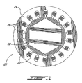
- an electric machine 20 such as a motor/generator generally includes a rotor 22 and a stator 24, the stator having at least one winding 26 in accordance with one aspect of the present invention, as described in further detail below.
- the magnetic rotor 22 rotates within the surrounding and stationary stator 24 having at least one current-carrying winding 26 disposed therein.
- a plurality of such windings 26 are circumferentially disposed about the stator 24.
- the electric machine 20 may be operated as a motor or a generator, or both, though it will be understood that heat dissipation in windings 26 will typically be a greater concern in a generator application.
- Winding (s) 26 are preferably bar-type conductors, as best seen in Fig. 3 described below.
- the windings 26 in successive slots 27 are typically appropriately connected by end turns (not shown) or a squirrel cage (not shown), depending on the machine type.
- the electric machine 20 as shown is an alternating current (AC) machine, however a direct current (DC) configuration is similarly possible.
- the present invention may be applied with any suitable electric machine architecture. Some electric machines can have very high current densities and thus, extensive cooling of the windings may become necessary.
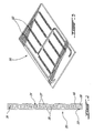
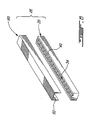
- a portion 30 of a winding 26 of the type described in commonly-assigned co-pending U.S. patent application serial no. 10/864,360 is depicted in axial cross-section, such that the inside of the winding portion is visible.
- Portion 30, in this embodiment, represents the portion of the winding disposed in a slot 27 of the stator 24 (i.e. the portion of the winding between successive end turns). Typically, it is this "leg" portion of the winding which has the most difficult heat rejection requirements.
- the winding portion 30 comprises a winding conductor body 32, which can be any suitable conductor material (e.g. copper, aluminum, etc.) within which a cooling flow passage 34 is formed.
- the cooling flow passage 34 extends in fluid flow communication between a coolant fluid inlet 36 at one end of the winding and a coolant fluid outlet 38 at an opposed end of the winding portion.
- a source of coolant such as an oil system (not shown or a coolant fluid system, is in fluid communication with the inlet 36 to provide 'fresh' coolant thereto, and with outlet 38 to retrieve 'spent' coolant therefrom for return to the oil or other system.
- the coolant flow passage 34 defines a tortuous flow path, defined impressed within a substantially flat surface 40 of the winding body 32.
- the tortuous coolant flow passage 34 defines a serpentine and sinuous configuration which includes a plurality of alternating first channel segments 35 and second channel segments 37 in fluid flow communication and arranged substantially perpendicular to one another.
- first channel segments 35 and second channel segments 37 in fluid flow communication and arranged substantially perpendicular to one another.
- other fluid flow paths are alternately possible.
- the fluid flow passage 34 is formed within the portion 30 of the winding 26 by impressing the channel within the outer surface 40 of the winding portion.
- impress and “impressing” as used herein are intended to include any operation which involves pressing a die, having a pattern and configuration of the desired coolant flow path, into the surface 40 of the portion 30 of the winding 26 in order to deform the material of the winding portion and thus form the coolant passage 34 therewithin.
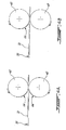
- the die may be disposed on a roller, as shown in Figs. 4a-4b, or a flat stamping plate, as shown in Figs. 5a-5b, for example.
- the impression of the coolant passage or channel 34 within the winding may be made using at least one roller on which the die is located and/or a linearly displacing flat stamping plate.
- a roller is used, as depicted schematically in Figs. 4a-4b, the material 31 which is to be used to form the winding portion 30, such as copper flat stock for example, is fed between a pair of opposed rollers 42, at least one of which includes the die 44 (i.e. the inverse of the cooling pattern to be impressed into the surface of the winding portion) thereon.
- Fig. 4b depicts such an embodiment wherein the die 44 is disposed on only a single one (the top one in the case of the embodiment depicted) of the opposed rollers 42.
- both of the pinching rollers through which the material is fed may have an impression die thereon (as shown in Fig. 4a), such that both sides of the material have the cooling flow channels impressed therein as the material sheet is forced between the rollers.
- At least one, but preferably both, of the two pinching rollers 42 are powered.
- the rollers may be coupled together by gear teeth (not shown) formed as a part of the rollers, in which case only a first one of the two rollers 42 is actually externally driven, while the second roller is driven by the first.
- gear teeth not shown
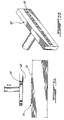
- a die 46 corresponding to the desired fluid flow coolant passage is disposed on a flat stamping plate 48 beneath which the winding material 31 is accordingly placed, and the entire winding portion 30 is stamped by the press plate 48 in order to form the fluid flow coolant channel 34 therein in a single stamping operation.
- Forming the open-topped fluid flow channel 34 in the portion 30 of the winding 26 by using an impressing method as described permits improved time and cost effective manufacture of the small fluid flow passages 34 within the windings 26, in comparison with other manufacturing techniques such as milling, routing, etching or electric discharge machining for example.
- a flat heat-exchanger plate 50 is similarly impressed (whether by roller, flat press, or otherwise) such as to form a plurality of fluid flow passages 52 therein.
- the plate 50 may be either used whole as a heat sink for dissipating heat from electronic equipment for example, or may be subdivided, into several individual portions therefore to be used as windings 26 in an electrical machine 20.
- the sub-division of the larger plate 50 into individual windings may be performed either following the step of impressing the fluid flow passage 52 therein, or simultaneously thereof (for example, the flat stamping plate 48 has the die 46 thereon for impressing the channels in the plate, and additionally has cutters for splitting the plate 50 into smaller winding 26).
- a closure 60 having a lower planar sealing surface 62 is abutted against the substantially flat peripheral surface 40 of the winding body portion 30 and is sealingly fastened thereto such as to enclose the channel 34 to form a fluid flow passage within the winding through which coolant fluid may be fed under pressure.
- the closure 60 is fastened to the peripheral surface 40 the winding body 30 about a perimeter thereof, outward from the channel 34 defined therein. While the closure 60 of the winding 26 may, in an alternately embodiment, be similarly provided with a corresponding (but mirror image) channel 34 therein, the closure 60 which forms a second portion of the winding body is preferably simply a flat sealing member which serves to enclose and seal the open-topped channel 34 formed in the body portion 30 of the winding 26.
- the closure 60 may therefore be either the same (in terms of dimensions, material, etc.) as the first body portion 30 but without a channel formed therein or alternately may be a relatively thin sealing sheet, such as one made of metal foil, plastic, polymer, a combination thereof or another suitable material which can be fastened to the main body 30 of the winding and will seal the open-topped channel 34 therein.
- the closure 60 includes a lower planar sealing surface 62 which can be wrapped over at least the peripheral surface 40 of the winding body 30, and preferably all the way around at least the longitudinal side walls of the winding 26, as shown in Fig. 6.
- planar sealing surface 62 of the closure 60 abuts against the substantially flat peripheral surface 40 of the winding body 30, and defines at least a part of a wall enclosing the fluid flow passage when sealingly fastened to the winding body 30. This permits a relatively quick and cost-effective method of sealing the open-topped channel 34 formed within the first portion 30 of the winding by impressing the fluid flow path die therein as described above.
Landscapes
- Engineering & Computer Science (AREA)
- Power Engineering (AREA)
- Manufacturing & Machinery (AREA)
- Motor Or Generator Cooling System (AREA)
- Manufacture Of Motors, Generators (AREA)
Applications Claiming Priority (1)
| Application Number | Priority Date | Filing Date | Title |
|---|---|---|---|
| US11/412,897 US7476993B2 (en) | 2006-04-28 | 2006-04-28 | Method of making electric machine winding |
Publications (2)
| Publication Number | Publication Date |
|---|---|
| EP1850459A2 true EP1850459A2 (de) | 2007-10-31 |
| EP1850459A3 EP1850459A3 (de) | 2011-05-18 |
Family
ID=38117209
Family Applications (1)
| Application Number | Title | Priority Date | Filing Date |
|---|---|---|---|
| EP07251800A Withdrawn EP1850459A3 (de) | 2006-04-28 | 2007-04-30 | Methode zur Herstellung einer Wicklung einer elektrischen Maschine |
Country Status (4)
| Country | Link |
|---|---|
| US (1) | US7476993B2 (de) |
| EP (1) | EP1850459A3 (de) |
| CA (1) | CA2643425C (de) |
| WO (1) | WO2007124584A1 (de) |
Families Citing this family (3)
| Publication number | Priority date | Publication date | Assignee | Title |
|---|---|---|---|---|
| US8198762B2 (en) * | 2008-01-31 | 2012-06-12 | Pratt & Whitney Canada Corp. | Winding end turn cooling in an electric machine |
| US9819239B2 (en) | 2015-05-07 | 2017-11-14 | Hamilton Sundstrand Corporation | End winding support and heat sink for liquid-cooled generator |
| US11876405B2 (en) | 2020-01-14 | 2024-01-16 | Hamilton Sundstrand Corporation | Electric motor with cooling channels |
Citations (2)
| Publication number | Priority date | Publication date | Assignee | Title |
|---|---|---|---|---|
| US3098941A (en) | 1960-10-27 | 1963-07-23 | Gen Electric | Dynamoelectric machine winding with edge-standing fluid-cooled conductors |
| WO2005121684A1 (en) | 2004-06-10 | 2005-12-22 | Pratt & Whitney Canada Corp. | Heat exchange device and method |
Family Cites Families (30)
| Publication number | Priority date | Publication date | Assignee | Title |
|---|---|---|---|---|
| US1821250A (en) * | 1929-12-28 | 1931-09-01 | Westinghouse Lamp Co | Wire-coiling die |
| US3119033A (en) * | 1961-11-07 | 1964-01-21 | Parsons C A & Co Ltd | Dynamo-electric machines |
| SE318939B (de) * | 1965-03-17 | 1969-12-22 | Asea Ab | |
| DE1763579A1 (de) * | 1968-06-26 | 1971-11-11 | Siemens Ag | Anordnung zur Fluessigkeitskuehlung der Staenderblechpakete elektrischer Maschinen,insbesondere fuer Turbogeneratoren |
| SE374429B (de) * | 1972-09-13 | 1975-03-03 | Saab Scania Ab | |
| US4028653A (en) * | 1976-04-01 | 1977-06-07 | Asea Aktiebolag | Electrical equipment having radial cooling channels with means for guiding cooling fluid through the channels |
| US4384168A (en) * | 1981-05-12 | 1983-05-17 | The United States Of America As Represented By The Department Of Energy | Conductor for a fluid-cooled winding |
| US4798241A (en) * | 1983-04-04 | 1989-01-17 | Modine Manufacturing | Mixed helix turbulator for heat exchangers |
| US4516044A (en) * | 1984-05-31 | 1985-05-07 | Cincinnati Milacron Inc. | Heat exchange apparatus for electric motor and electric motor equipped therewith |
| USRE33528E (en) * | 1985-02-11 | 1991-01-29 | Microtube-strip heat exchanger | |
| US4908537A (en) * | 1988-04-27 | 1990-03-13 | Westinghouse Electric Corp. | Pole ventilation of radially ventilated rotors |
| US4899812A (en) * | 1988-09-06 | 1990-02-13 | Westinghouse Electric Corp. | Self-securing turbulence promoter to enhance heat transfer |
| US5578879A (en) * | 1989-09-28 | 1996-11-26 | Heidelberg; G+E,Uml O+Ee Tz | Electric machine with fluid cooling |
| US5107922A (en) * | 1991-03-01 | 1992-04-28 | Long Manufacturing Ltd. | Optimized offset strip fin for use in contact heat exchangers |
| US5291943A (en) * | 1992-12-29 | 1994-03-08 | The Regents Of The University Of California | Heat transfer enhancement using tangential injection |
| US5491371A (en) * | 1993-12-13 | 1996-02-13 | Able Corporation | Electrical machinery laminations cooling |
| US6362545B1 (en) * | 1994-11-04 | 2002-03-26 | General Electric Company | Dynamoelectric machines having rotor windings with turbulated cooling passages |
| US5638900A (en) * | 1995-01-27 | 1997-06-17 | Ail Research, Inc. | Heat exchange assembly |
| US5623175A (en) * | 1996-03-19 | 1997-04-22 | General Motors Corporation | Thermally efficient, liquid cooled housing for dynamoelectric machine |
| JP4175443B2 (ja) * | 1999-05-31 | 2008-11-05 | 三菱重工業株式会社 | 熱交換器 |
| AU2001245588A1 (en) * | 2000-03-10 | 2001-09-24 | Satcon Technology Corporation | High performance cold plate for electronic cooling |
| US6498408B2 (en) * | 2000-12-20 | 2002-12-24 | General Electric Company | Heat transfer enhancement at generator stator core space blocks |
| US6504274B2 (en) * | 2001-01-04 | 2003-01-07 | General Electric Company | Generator stator cooling design with concavity surfaces |
| DE10112532A1 (de) * | 2001-03-15 | 2002-10-02 | Siemens Ag | Luftgekühlte elektrische rotatorische Maschine |
| GB2378046A (en) * | 2001-07-18 | 2003-01-29 | Turbo Genset Company Ltd | Cooling flow in discoid stator windings |
| US6615911B1 (en) * | 2002-03-07 | 2003-09-09 | Delphi Technologies, Inc. | High performance liquid-cooled heat sink with twisted tape inserts for electronics cooling |
| US6628020B1 (en) * | 2002-05-21 | 2003-09-30 | General Electric Company | Heat transfer enhancement of ventilation grooves of rotor end windings in dynamoelectric machines |
| DE10246990A1 (de) * | 2002-10-02 | 2004-04-22 | Atotech Deutschland Gmbh | Mikrostrukturkühler und dessen Verwendung |
| KR100998039B1 (ko) * | 2003-10-01 | 2010-12-03 | 삼성테크윈 주식회사 | 기판 제조 방법 및 이를 이용하여 제조된 스마트 라벨 |
| US7633194B2 (en) * | 2006-10-26 | 2009-12-15 | Gm Global Technology Operations, Inc. | Apparatus for cooling stator lamination stacks of electrical machines |
-
2006
- 2006-04-28 US US11/412,897 patent/US7476993B2/en not_active Expired - Fee Related
-
2007
- 2007-04-27 CA CA2643425A patent/CA2643425C/en not_active Expired - Fee Related
- 2007-04-27 WO PCT/CA2007/000726 patent/WO2007124584A1/en not_active Ceased
- 2007-04-30 EP EP07251800A patent/EP1850459A3/de not_active Withdrawn
Patent Citations (2)
| Publication number | Priority date | Publication date | Assignee | Title |
|---|---|---|---|---|
| US3098941A (en) | 1960-10-27 | 1963-07-23 | Gen Electric | Dynamoelectric machine winding with edge-standing fluid-cooled conductors |
| WO2005121684A1 (en) | 2004-06-10 | 2005-12-22 | Pratt & Whitney Canada Corp. | Heat exchange device and method |
Also Published As
| Publication number | Publication date |
|---|---|
| US7476993B2 (en) | 2009-01-13 |
| WO2007124584A1 (en) | 2007-11-08 |
| CA2643425C (en) | 2015-12-15 |
| CA2643425A1 (en) | 2007-11-08 |
| US20070252450A1 (en) | 2007-11-01 |
| EP1850459A3 (de) | 2011-05-18 |
Similar Documents
| Publication | Publication Date | Title |
|---|---|---|
| US8072100B2 (en) | Stator for an electrical machine with liquid cooling | |
| DE112017000278B4 (de) | Elektrische Rotationsmaschine | |
| US9748803B2 (en) | Electric machine | |
| Popescu et al. | Modern heat extraction systems for electrical machines-A review | |
| EP1257043B1 (de) | Kühlung für elektrische Maschinen | |
| EP2182570A1 (de) | Anordnung zur Kühlung einer elektrischen Maschine | |
| EP1276205B1 (de) | Rotorkühlanordnung einer elektrischen Maschine | |
| EP0461906A2 (de) | Ständerkühlungssystem für eine elektrische Maschine | |
| EP2086090A1 (de) | Spulenanordnung für drehende elektrische Maschine, Stator für drehende elektrische Maschine und drehende elektrische Maschine | |
| CN108880043B (zh) | 电机以及用于制造电机的方法 | |
| US20130076171A1 (en) | Electric machine module cooling system and method | |
| US20130076167A1 (en) | Cooling system and method for electronic machines | |
| CA2643425C (en) | Method of making electric machine winding | |
| EP2398129B1 (de) | Generator, insbesondere für eine Windturbine | |
| EP3935716A1 (de) | Verfahren und vorrichtung zur motorkühlung | |
| US20240055951A1 (en) | Induction rotor with end ring cooling features | |
| JP2006320104A (ja) | 電動機のコイル冷却構造 | |
| JP2004512792A (ja) | 成層鉄心 | |
| MXPA02005703A (es) | Paquete de laminillas de hoja. | |
| JP2007159286A (ja) | リニアモータ | |
| JP2007159286A5 (de) | ||
| BR112023002469B1 (pt) | Turbina eólica tendo pelo menos uma máquina dinamoelétrica, e, método para produzir um ou mais canais de resfriamento |
Legal Events
| Date | Code | Title | Description |
|---|---|---|---|
| PUAI | Public reference made under article 153(3) epc to a published international application that has entered the european phase |
Free format text: ORIGINAL CODE: 0009012 |
|
| AK | Designated contracting states |
Kind code of ref document: A2 Designated state(s): AT BE BG CH CY CZ DE DK EE ES FI FR GB GR HU IE IS IT LI LT LU LV MC MT NL PL PT RO SE SI SK TR |
|
| AX | Request for extension of the european patent |
Extension state: AL BA HR MK YU |
|
| PUAL | Search report despatched |
Free format text: ORIGINAL CODE: 0009013 |
|
| AK | Designated contracting states |
Kind code of ref document: A3 Designated state(s): AT BE BG CH CY CZ DE DK EE ES FI FR GB GR HU IE IS IT LI LT LU LV MC MT NL PL PT RO SE SI SK TR |
|
| AX | Request for extension of the european patent |
Extension state: AL BA HR MK RS |
|
| 17P | Request for examination filed |
Effective date: 20111116 |
|
| AKX | Designation fees paid |
Designated state(s): DE FR GB |
|
| 17Q | First examination report despatched |
Effective date: 20120202 |
|
| STAA | Information on the status of an ep patent application or granted ep patent |
Free format text: STATUS: THE APPLICATION HAS BEEN WITHDRAWN |
|
| 18W | Application withdrawn |
Effective date: 20160311 |