EP1850325A1 - Machine prognostics and health monitoring using speech recognition techniques - Google Patents
Machine prognostics and health monitoring using speech recognition techniques Download PDFInfo
- Publication number
- EP1850325A1 EP1850325A1 EP07251799A EP07251799A EP1850325A1 EP 1850325 A1 EP1850325 A1 EP 1850325A1 EP 07251799 A EP07251799 A EP 07251799A EP 07251799 A EP07251799 A EP 07251799A EP 1850325 A1 EP1850325 A1 EP 1850325A1
- Authority
- EP
- European Patent Office
- Prior art keywords
- sound
- machine
- data
- speech recognition
- health monitoring
- Prior art date
- Legal status (The legal status is an assumption and is not a legal conclusion. Google has not performed a legal analysis and makes no representation as to the accuracy of the status listed.)
- Withdrawn
Links
Images

Classifications
-
- G—PHYSICS
- G07—CHECKING-DEVICES
- G07C—TIME OR ATTENDANCE REGISTERS; REGISTERING OR INDICATING THE WORKING OF MACHINES; GENERATING RANDOM NUMBERS; VOTING OR LOTTERY APPARATUS; ARRANGEMENTS, SYSTEMS OR APPARATUS FOR CHECKING NOT PROVIDED FOR ELSEWHERE
- G07C3/00—Registering or indicating the condition or the working of machines or other apparatus, other than vehicles
-
- F—MECHANICAL ENGINEERING; LIGHTING; HEATING; WEAPONS; BLASTING
- F02—COMBUSTION ENGINES; HOT-GAS OR COMBUSTION-PRODUCT ENGINE PLANTS
- F02D—CONTROLLING COMBUSTION ENGINES
- F02D41/00—Electrical control of supply of combustible mixture or its constituents
- F02D41/22—Safety or indicating devices for abnormal conditions
-
- G—PHYSICS
- G01—MEASURING; TESTING
- G01M—TESTING STATIC OR DYNAMIC BALANCE OF MACHINES OR STRUCTURES; TESTING OF STRUCTURES OR APPARATUS, NOT OTHERWISE PROVIDED FOR
- G01M15/00—Testing of engines
- G01M15/04—Testing internal-combustion engines
- G01M15/12—Testing internal-combustion engines by monitoring vibrations
-
- G—PHYSICS
- G01—MEASURING; TESTING
- G01M—TESTING STATIC OR DYNAMIC BALANCE OF MACHINES OR STRUCTURES; TESTING OF STRUCTURES OR APPARATUS, NOT OTHERWISE PROVIDED FOR
- G01M15/00—Testing of engines
- G01M15/14—Testing gas-turbine engines or jet-propulsion engines
-
- G—PHYSICS
- G10—MUSICAL INSTRUMENTS; ACOUSTICS
- G10L—SPEECH ANALYSIS OR SYNTHESIS; SPEECH RECOGNITION; SPEECH OR VOICE PROCESSING; SPEECH OR AUDIO CODING OR DECODING
- G10L15/00—Speech recognition
- G10L15/26—Speech to text systems
-
- F—MECHANICAL ENGINEERING; LIGHTING; HEATING; WEAPONS; BLASTING
- F02—COMBUSTION ENGINES; HOT-GAS OR COMBUSTION-PRODUCT ENGINE PLANTS
- F02D—CONTROLLING COMBUSTION ENGINES
- F02D2200/00—Input parameters for engine control
- F02D2200/02—Input parameters for engine control the parameters being related to the engine
- F02D2200/025—Engine noise, e.g. determined by using an acoustic sensor
-
- Y—GENERAL TAGGING OF NEW TECHNOLOGICAL DEVELOPMENTS; GENERAL TAGGING OF CROSS-SECTIONAL TECHNOLOGIES SPANNING OVER SEVERAL SECTIONS OF THE IPC; TECHNICAL SUBJECTS COVERED BY FORMER USPC CROSS-REFERENCE ART COLLECTIONS [XRACs] AND DIGESTS
- Y02—TECHNOLOGIES OR APPLICATIONS FOR MITIGATION OR ADAPTATION AGAINST CLIMATE CHANGE
- Y02T—CLIMATE CHANGE MITIGATION TECHNOLOGIES RELATED TO TRANSPORTATION
- Y02T10/00—Road transport of goods or passengers
- Y02T10/10—Internal combustion engine [ICE] based vehicles
- Y02T10/40—Engine management systems
Definitions
- the invention relates generally to health monitoring of machines.
- the present invention provides a method of monitoring the health of a machine using a health monitoring system, the method comprising the steps of: capturing sound produced by the machine during operation thereof; and comparing the sound to known reference sounds.
- the present invention provides a method of monitoring the health of a machine using a health monitoring system, the method comprising the steps of: intermittently capturing sound data of the engine in operation; and comparing the sound data to known sound data to determine a health condition of the machine.
- a gas turbine engine health monitoring system comprising at least one microphone communicating with a sound recognition system.
- Fig.1 illustrates a gas turbine engine 10 of a type preferably provided for use in subsonic flight, generally comprising in serial flow communication a fan 12 through which ambient air is propelled, a multistage compressor 14 for pressurizing the air, a combustor 16 in which the compressed air is mixed with fuel and ignited for generating an annular stream of hot combustion gases, and a turbine section 18 for extracting energy from the combustion gases.
- the present invention permits health monitoring of various machines, including such a gas turbine engine 10. However, it is to be understood that any type of machine may be monitored as described in further detail below.
- the term "machine” as used herein will be understood to include any mechanical system in motion, such as the example gas turbine engine 10 considered herein.
- the system and method of one aspect of the present invention permits machine sensor data, obtained from a sensor such as a microphone for example, to be captured and employed for the purpose of determining the health of the machine in question, whether a gas turbine engine 10 or another type of machine.
- a sensor such as a microphone for example
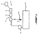
- the monitoring system 25 includes a microphone or vibration sensor assembly 30, containing one or more of such devices, which communicates with a sound recognition system 33 including a data analyzer 34, described further below, a signal conditioner 35 and a data collector/transmitter 32.
- the sound recognition system 33 communicates with a controller 36 of the machine 10 (such as an electronic engine controller of the gas turbine engine 10) and with a preferably central knowledge base 37.
- the number, type and placement of microphones/sensors employed in microphone/vibration assembly 30 depends on the machine type, size and parameters to be monitored, among other things.
- two microphones 30 are preferably provided and mounted under the engine cowling.
- the signal conditioner, data collector/transmitter 32 and the data analyzer 34 may also be incorporated together in a common assembly, or alternately a single device (such as a microcomputer) may perform the roles of each of these components.
- the data analyzer 34 includes a computer having at least one human speech recognition software algorithm installed/programmed therein, which is capable of comparing the captured sound data from the microphone(s) to known or reference sound data, preferably stored onboard within the monitoring system.
- Suitable human speech recognition systems include those based on Hidden Markov Model ("HMM") techniques. Systems having both analysis and probability functions are preferred, are commercially available, can be quite small and may be inexpensively obtained.
- the speech recognition system is trained to recognise "words" indicative of the machine's health and operational conditions, as desired.
- the recognition system includes a probability calculation on "word” matching, and has some form of output code generator, to indicate whether a word is known or unknown, healthy or unhealthy, which "word” has been recognised and the probability of correct match.
- a signal conditioning module 35 may be desirable, depending on the requirements of the speech recognition system selected, to condition the sound signal prior to providing it to the data analyzer 34 of the speech recognition system, such as to make the frequency content or volume compatible with the selected speech recognition (e.g. to bring the signal frequencies into the typical human speech range expected by commercially-available speech recognition systems).
- signal conditioning module 35 modifies captured data in a pre-determined manner, perhaps determined in part on the type or timing of sound data captured (that is, different expected data may have different frequency spectra), with the objective of causing the data to be better handled by the speech recognition system. For example, captured data of a first type (e.g. engine run-up) is modified in a first way, based on the expected frequencies, volume, etc.
- Data modification may include frequency filtering and/or transposing out-of-range frequencies into in-range frequencies (e.g. low frequency sounds could be speed up, or very high frequency sounds slowed down, to yield something more processable by the system), and/or other suitable operations.
- the requirements (if any) of the signal conditioning module 35 will be determined, in large part, by the input requirements of the selected sound recognition system.
- the microphone or vibration sensor 30 captures data (e.g. in random access memory) representing sound or other vibration generated by the machine during its operation, and transmits the data representative of the sound or other vibration to sound recognition system 33, where the data is conditioned, if necessary, to meet the input requirements of the data analyzer 34.
- the data analyzer 34 compares the captured sound data to known sounds, to determine whether the captured sound is known, and whether it is representative of a healthy operating condition, or an abnormal, sub-optimal, deterioration or problematic condition.
- the data is preferably processed by the data analyzer 34 to permit the data to be analyzed according to speech recognition techniques, as will also be described below.
- the sound data may also, if desired, be recorded or stored, or transmitted for remote recording or storage, by the data collector/transmitter 32 for further processing.
- the data is preferably pre-processed by the signal conditioner 36 prior to analysis to permit the data to be analyzed according to speech recognition techniques.
- data is captured intermittently, preferably over relatively short durations (e.g. 1 to 3 seconds, or shorter, or longer, but preferably less than, say, 5 seconds), to form discrete "words” of data to improve comparing/matching accuracy.
- the "words” are then provided to an appropriately trained speech recognition system contained therein, which analyzes the captured "words” of sound data to determine whether these "words” are known or unknown, and whether the "words" are likely to indicate a healthy engine, or an unhealthy one.
- the intermittent capturing is synchronized with specific engine operational parameters, and designed to locate specific indicators of health, or deterioration, of the machine.
- these specific engine operations may include acceleration through a particular speed range.
- data capture is triggered to start at a given high pressure shaft speed (sometimes referred to as "N2") during a normal acceleration to aircraft take-off, and capturing of the sounds generated is terminated at a second pre-selected N2 speed.
- N2 high pressure shaft speed
- Similar "sound bites" may be captured and analyzed.
- engine steady state i.e. cruise
- the captured “words” may be designed to capture the presence (or absence) of vibration, pressure fluctuations in the gas path, compressor surge, engine speed instability, blade tip rubs, sounds related to gearbox operation, as well as general loose or rattling components or surging, or run down noises, and/or any other suitable event or condition.
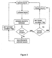
- the data analyzer 34 is pre-programmed or "trained” with suitable "vocabulary", such that is as able to identify and distinguish between sound data which is representative of normal healthy engine data, and that what is data indicative of engine problems or conditions requiring action or noting.
- suitable "vocabulary” such that is as able to identify and distinguish between sound data which is representative of normal healthy engine data, and that what is data indicative of engine problems or conditions requiring action or noting.
- the captured data is recognised as a normal sound, preferably no specific action is taken. If the sound is recognised as a known problem or indicator, requiring specific service action, a flag indicating the action required, or a code representing the required action, is set for later retrieval, or for immediate or later transmittal to a central location, such as a service centre for the machine.
- a flag indicating, for example, that the further investigation is required is set for later retrieval, or for immediate or later transmittal to a central location, such as the machine manufacturer's diagnostic centre, preferably along with the sound itself, and also preferably along with other specific machine operating information associated with the unknown condition, to provide other potentially useful information to the diagnostic centre.
- the diagnostic centre preferably uses its available resources to determine the cause of the unknown sound, and an appropriate action required for this machine. If necessary, the diagnostic centre will dispatch an appropriate team or action to acquire more data (e.g. from the machine itself, once it is serviced), in order to determine the cause of the sound, and an appropriate associated action required.
- a knowledge base is updated, and preferably the newly recognized sound is then transmitted back, preferably with an associated flag or action associated, to sound recognition system 33.
- This process potentially allows the diagnostic centre to identify the unknown condition off-line, and then upload the appropriate flag or service action back to the sound recognition system 33, or to the appropriate service record for machine 10.
- This also allows the newly recognized sound to be recognised again in the future, should it reoccur, and then the appropriate service action or flags can be set as required.
- all similar systems in service elsewhere are periodically updated with all such new reference data, as well.
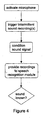
- the analyzer may either simply discard the data or cause a healthy status flag to be recorded for that particular time. If the "word” or sound is recognized as unhealthy and having a specific meaning, again, to conserve recording space the analyzer may either simply discard the data or cause an appropriate "specific unhealthy” status flag to be recorded for that particular time. If the "word” is not recognized at all, preferably it is saved or stored, and a suitable flag set. As mentioned, correlation of unknown "words” by detailed analysis and/or by maintenance records, leads to an improved "vocabulary" which may be used for prognostics, diagnostics and general health monitoring of the machine.
- Microphones are preferred because of their wide dynamic range of sensitivity of any sensor type and can detect vibration, pressure fluctuations, sounds generated by the flow of fluid within the machine, transmission related sounds, as well as sounds caused by loose or rattling components.
- sounds such as compressor surge, speed instability, or run down noises rubs, gas path flow noise, gearbox generated sounds, and the like can also be detected by the microphone 30.
- microphones are preferred as the sensor 30, a vibration sensor or other suitable sensors may also be used which permit the detection of audible or non-audible pressure waves generated by machine during the operation thereof.
- the sound data from the microphone or vibration sensor 30 is collected and analyzed in conjunction with that of other sensors (e.g.
- Vibration transducers may be used in conjunction with the microphones or alone, and the signal(s) may require preconditioning prior to providing the sound recognition system.
- the sound recognition system when used with vibration sensors, is preferably provided with reference vibration data for comparison purposes, rather than sound data, per se.
- the present invention may be used in conjunction with existing data collection systems, or may be used to replace existing systems.
- Microphones offer the advantages of not having to be directly attached to the engine, reducing life problems associated with connectors exposed to vibration over long periods, and so on.
- a small sound generator 40 may be co-located with the microphone 30 such that the monitoring system 25 is able self-check its own health, preferably when the machine 10 stopped, to verify that the monitoring system 25 is in good working order.
- the present embodiment applies to any suitable system for which the health condition monitoring is desired.
- communication lines are depicted in Fig. 2, it will be understood that the communications may be wireless, such as by a wireless connection.
- the data collector and/or data analyzer may not be mounted on or in proximity to the machine, and, in the case of a gas turbine engine 10, may not even be located on the aircraft but rather at a remote location, and may communicate with the monitoring system 25 via a computer network, such as the World Wide Web.
- the monitoring system is preferably used to monitor the health of a gas turbine engine, it may be used to monitor any machine such as an internal combustion engine, an electric motor or generator, and the like.
- the data analyzer 34 preferably uses a speech recognition algorithm(s) to perform such a step of comparing the captured sound data to that of known sounds, other software can be alternately used to perform this function. Still other modifications which fall within the scope of the present invention will be apparent to those skilled in the art, in light of a review of this disclosure, and such modifications are intended to fall within the appended claims.
Abstract
Description
- The invention relates generally to health monitoring of machines.
- Monitoring of various parameters indicative of a machine's operation can be useful in determining the health of the machine, and predicting when and what type of service may soon be required for the machine. Machines of all types are subject to health monitoring, and data about machine operation may be gathered in many different ways and reflecting a multitude of parameters. Nonetheless, there exists room for improvement.
- In one aspect, the present invention provides a method of monitoring the health of a machine using a health monitoring system, the method comprising the steps of: capturing sound produced by the machine during operation thereof; and comparing the sound to known reference sounds.
- In a second aspect, the present invention provides a method of monitoring the health of a machine using a health monitoring system, the method comprising the steps of: intermittently capturing sound data of the engine in operation; and comparing the sound data to known sound data to determine a health condition of the machine.
- There is also provided, in accordance with another aspect of the present invention, a gas turbine engine health monitoring system comprising at least one microphone communicating with a sound recognition system.
- Further details of these and other aspects of the present invention will be apparent from the detailed description and figures included below.
- Reference is now made to the accompanying figures depicting aspects of the present invention, in which:
- Fig. 1 is a schematic cross-sectional view of a gas turbine engine;
- Fig. 2 is schematic view of a system for monitoring a machine in accordance with an aspect of the present invention;
- Fig. 3 is a flow chart of a method of monitoring the health of a machine in accordance with an aspect of the present invention; and
- Fig. 4 is a flow chart depicting an embodiment of a method of processing and analyzing machine sound captured according to the method of Fig. 3.
- Fig.1 illustrates a
gas turbine engine 10 of a type preferably provided for use in subsonic flight, generally comprising in serial flow communication afan 12 through which ambient air is propelled, amultistage compressor 14 for pressurizing the air, acombustor 16 in which the compressed air is mixed with fuel and ignited for generating an annular stream of hot combustion gases, and aturbine section 18 for extracting energy from the combustion gases. The present invention permits health monitoring of various machines, including such agas turbine engine 10. However, it is to be understood that any type of machine may be monitored as described in further detail below. The term "machine" as used herein will be understood to include any mechanical system in motion, such as the examplegas turbine engine 10 considered herein. - The system and method of one aspect of the present invention permits machine sensor data, obtained from a sensor such as a microphone for example, to be captured and employed for the purpose of determining the health of the machine in question, whether a
gas turbine engine 10 or another type of machine. Thus, early warning of impending problems and/or diagnosis of existing problems with the normal functioning of a system, such as an engine system, is possible. - Referring to Fig. 2, a
monitoring system 25 for monitoring the health of a machine, such asgas turbine 10, is depicted. Themonitoring system 25 includes a microphone orvibration sensor assembly 30, containing one or more of such devices, which communicates with asound recognition system 33 including adata analyzer 34, described further below, asignal conditioner 35 and a data collector/transmitter 32. In the embodiment depicted, thesound recognition system 33 communicates with acontroller 36 of the machine 10 (such as an electronic engine controller of the gas turbine engine 10) and with a preferablycentral knowledge base 37. The number, type and placement of microphones/sensors employed in microphone/vibration assembly 30 depends on the machine type, size and parameters to be monitored, among other things. In the case of an aircraftgas turbine engine 10, twomicrophones 30 are preferably provided and mounted under the engine cowling. The signal conditioner, data collector/transmitter 32 and thedata analyzer 34 may also be incorporated together in a common assembly, or alternately a single device (such as a microcomputer) may perform the roles of each of these components. - In one embodiment, the
data analyzer 34 includes a computer having at least one human speech recognition software algorithm installed/programmed therein, which is capable of comparing the captured sound data from the microphone(s) to known or reference sound data, preferably stored onboard within the monitoring system. Suitable human speech recognition systems include those based on Hidden Markov Model ("HMM") techniques. Systems having both analysis and probability functions are preferred, are commercially available, can be quite small and may be inexpensively obtained. The speech recognition system is trained to recognise "words" indicative of the machine's health and operational conditions, as desired. Preferably, as mentioned, the recognition system includes a probability calculation on "word" matching, and has some form of output code generator, to indicate whether a word is known or unknown, healthy or unhealthy, which "word" has been recognised and the probability of correct match. - A
signal conditioning module 35 may be desirable, depending on the requirements of the speech recognition system selected, to condition the sound signal prior to providing it to thedata analyzer 34 of the speech recognition system, such as to make the frequency content or volume compatible with the selected speech recognition (e.g. to bring the signal frequencies into the typical human speech range expected by commercially-available speech recognition systems). Preferably,signal conditioning module 35 modifies captured data in a pre-determined manner, perhaps determined in part on the type or timing of sound data captured (that is, different expected data may have different frequency spectra), with the objective of causing the data to be better handled by the speech recognition system. For example, captured data of a first type (e.g. engine run-up) is modified in a first way, based on the expected frequencies, volume, etc. of such data type, while captured data of a second type (e.g. engine spool-down) is modified in a second way, based on another set of expected frequencies, etc., and so on. Data modification may include frequency filtering and/or transposing out-of-range frequencies into in-range frequencies (e.g. low frequency sounds could be speed up, or very high frequency sounds slowed down, to yield something more processable by the system), and/or other suitable operations. The skilled reader will appreciate, in light of the present disclosure, that the requirements (if any) of thesignal conditioning module 35 will be determined, in large part, by the input requirements of the selected sound recognition system. - In use, as depicted in Figs. 3 and 4, while the
machine 10 is in operation the microphone orvibration sensor 30 captures data (e.g. in random access memory) representing sound or other vibration generated by the machine during its operation, and transmits the data representative of the sound or other vibration tosound recognition system 33, where the data is conditioned, if necessary, to meet the input requirements of thedata analyzer 34. Thedata analyzer 34 compares the captured sound data to known sounds, to determine whether the captured sound is known, and whether it is representative of a healthy operating condition, or an abnormal, sub-optimal, deterioration or problematic condition. Prior to analysis, the data is preferably processed by thedata analyzer 34 to permit the data to be analyzed according to speech recognition techniques, as will also be described below. The sound data may also, if desired, be recorded or stored, or transmitted for remote recording or storage, by the data collector/transmitter 32 for further processing. - As mentioned, the data is preferably pre-processed by the
signal conditioner 36 prior to analysis to permit the data to be analyzed according to speech recognition techniques. In one embodiment, data is captured intermittently, preferably over relatively short durations (e.g. 1 to 3 seconds, or shorter, or longer, but preferably less than, say, 5 seconds), to form discrete "words" of data to improve comparing/matching accuracy. The "words" are then provided to an appropriately trained speech recognition system contained therein, which analyzes the captured "words" of sound data to determine whether these "words" are known or unknown, and whether the "words" are likely to indicate a healthy engine, or an unhealthy one. Preferably, the intermittent capturing is synchronized with specific engine operational parameters, and designed to locate specific indicators of health, or deterioration, of the machine. For example, for agas turbine engine 10 these specific engine operations may include acceleration through a particular speed range. In this case, data capture is triggered to start at a given high pressure shaft speed (sometimes referred to as "N2") during a normal acceleration to aircraft take-off, and capturing of the sounds generated is terminated at a second pre-selected N2 speed. As N2 increases, similar "sound bites" may be captured and analyzed. Likewise, during engine deceleration, or engine steady state (i.e. cruise) conditions may be monitored. The captured "words" may be designed to capture the presence (or absence) of vibration, pressure fluctuations in the gas path, compressor surge, engine speed instability, blade tip rubs, sounds related to gearbox operation, as well as general loose or rattling components or surging, or run down noises, and/or any other suitable event or condition. - Preferably, the
data analyzer 34 is pre-programmed or "trained" with suitable "vocabulary", such that is as able to identify and distinguish between sound data which is representative of normal healthy engine data, and that what is data indicative of engine problems or conditions requiring action or noting. Referring still to Fig. 3, if after comparing the captured data to known reference data, the captured data is recognised as a normal sound, preferably no specific action is taken. If the sound is recognised as a known problem or indicator, requiring specific service action, a flag indicating the action required, or a code representing the required action, is set for later retrieval, or for immediate or later transmittal to a central location, such as a service centre for the machine. If analysis determines the sound is unknown, a flag indicating, for example, that the further investigation is required is set for later retrieval, or for immediate or later transmittal to a central location, such as the machine manufacturer's diagnostic centre, preferably along with the sound itself, and also preferably along with other specific machine operating information associated with the unknown condition, to provide other potentially useful information to the diagnostic centre. The diagnostic centre preferably uses its available resources to determine the cause of the unknown sound, and an appropriate action required for this machine. If necessary, the diagnostic centre will dispatch an appropriate team or action to acquire more data (e.g. from the machine itself, once it is serviced), in order to determine the cause of the sound, and an appropriate associated action required. Either way, once the cause is determined, a knowledge base is updated, and preferably the newly recognized sound is then transmitted back, preferably with an associated flag or action associated, to soundrecognition system 33. This process potentially allows the diagnostic centre to identify the unknown condition off-line, and then upload the appropriate flag or service action back to thesound recognition system 33, or to the appropriate service record formachine 10. This also allows the newly recognized sound to be recognised again in the future, should it reoccur, and then the appropriate service action or flags can be set as required. Preferably all similar systems in service elsewhere, are periodically updated with all such new reference data, as well. - When the "words" of sound data are recognised as healthy engine "words" or sounds, to conserve on-board recording space the analyzer may either simply discard the data or cause a healthy status flag to be recorded for that particular time. If the "word" or sound is recognized as unhealthy and having a specific meaning, again, to conserve recording space the analyzer may either simply discard the data or cause an appropriate "specific unhealthy" status flag to be recorded for that particular time. If the "word" is not recognized at all, preferably it is saved or stored, and a suitable flag set. As mentioned, correlation of unknown "words" by detailed analysis and/or by maintenance records, leads to an improved "vocabulary" which may be used for prognostics, diagnostics and general health monitoring of the machine.
- Microphones are preferred because of their wide dynamic range of sensitivity of any sensor type and can detect vibration, pressure fluctuations, sounds generated by the flow of fluid within the machine, transmission related sounds, as well as sounds caused by loose or rattling components. In the case when the
machine 10 is agas turbine engine 10, sounds such as compressor surge, speed instability, or run down noises rubs, gas path flow noise, gearbox generated sounds, and the like can also be detected by themicrophone 30. Although microphones are preferred as thesensor 30, a vibration sensor or other suitable sensors may also be used which permit the detection of audible or non-audible pressure waves generated by machine during the operation thereof. In an other aspect, the sound data from the microphone orvibration sensor 30 is collected and analyzed in conjunction with that of other sensors (e.g. temperature sensors, pressure sensors, etc.), in such a way as to form a more complex "word", which is then analyzed by an appropriately trained voice recognition software program within thedata analyzer 34, to provide additional dimensions to the health data acquired. Vibration transducers may be used in conjunction with the microphones or alone, and the signal(s) may require preconditioning prior to providing the sound recognition system. The skilled reader will recognise that the sound recognition system, when used with vibration sensors, is preferably provided with reference vibration data for comparison purposes, rather than sound data, per se. - The present invention may be used in conjunction with existing data collection systems, or may be used to replace existing systems. Microphones offer the advantages of not having to be directly attached to the engine, reducing life problems associated with connectors exposed to vibration over long periods, and so on.
- Referring again to Fig. 2, a
small sound generator 40 may be co-located with themicrophone 30 such that themonitoring system 25 is able self-check its own health, preferably when themachine 10 stopped, to verify that themonitoring system 25 is in good working order. - As mentioned, the present embodiment applies to any suitable system for which the health condition monitoring is desired. Although communication lines are depicted in Fig. 2, it will be understood that the communications may be wireless, such as by a wireless connection. It will also be understood that the data collector and/or data analyzer may not be mounted on or in proximity to the machine, and, in the case of a
gas turbine engine 10, may not even be located on the aircraft but rather at a remote location, and may communicate with themonitoring system 25 via a computer network, such as the World Wide Web. - The above description is meant to be exemplary only, and one skilled in the art will recognize that changes may be made to the embodiments described without department from the scope of the invention disclosed. For example, although the monitoring system is preferably used to monitor the health of a gas turbine engine, it may be used to monitor any machine such as an internal combustion engine, an electric motor or generator, and the like. Additionally, although the
data analyzer 34 preferably uses a speech recognition algorithm(s) to perform such a step of comparing the captured sound data to that of known sounds, other software can be alternately used to perform this function. Still other modifications which fall within the scope of the present invention will be apparent to those skilled in the art, in light of a review of this disclosure, and such modifications are intended to fall within the appended claims.
Claims (22)
- A method of monitoring the health of a machine (10) using a health monitoring system (25), the method comprising the steps of:a. capturing sound produced by the machine (10) during operation thereof; andb. comparing the sound to known reference sounds.
- The method of claim 1, wherein the step of comparing includes using at least one human speech recognition algorithm to compare the sound to the known reference sounds.
- The method of claim 2, wherein the sound is conditioned prior to said comparing step, to adjust at least a frequency component of the sound.
- The method of claim 1, 2 or 3, wherein the step of capturing further comprises capturing the sound intermittently.
- The method of claim 4, wherein the step of capturing includes using a controller of the machine (10) to at least one of start and stop sound capture based on a machine parameter.
- The method of claim 5, wherein the machine parameter is a pre-determined machine speed.
- The method of any preceding claim, wherein the step of capturing is followed by the step of recording the sound.
- The method of any preceding claim, further comprising the step of transmitting data corresponding to the sound to a remote location.
- The method of any preceding claim, further comprising detecting a known condition of the machine (10) and setting a signal indicative of a required action associated with the known condition.
- A method of monitoring the health of a machine (10) using a health monitoring system, the method comprising the steps of:a. intermittently capturing sound data of the machine (10) in operation; andb. comparing the sound data to known sound data using a human speech recognition algorithm to determine a health condition of the machine.
- The method of claim 10, wherein the step of intermittently capturing includes using a controller to at least one of start and stop sound capture based on a machine operating parameter.
- The method of claim 11, wherein said at least one of starting and stopping the sound capture is based on an operating speed of the machine.
- The method of claim 10, 11 or 12, wherein the step of comparing includes using at least one speech recognition algorithm to compare the sound data to the known sound data.
- The method of any of claims 10 to 13, further comprising recording and storing the sound data along with additional machine operational data associated with the sound data.
- The method of any of claims 10 to 14, further comprising indicating the presence of an abnormal condition of the machine (10) when the captured sound data differs from the known sound data.
- The method of any preceding claim, wherein the step of capturing includes using at least one microphone (30) to capture sound produced by the machine (10).
- The method of any preceding claim, further comprising performing a calibration of the health monitoring system (25).
- The method of claim 17, wherein the step of calibration includes performing a self-check of the health monitoring system (25) using a sound generator (40).
- The method of claim 18, further comprising integrating the sound generator (40) within the health monitoring system (25) or the at least one microphone (30).
- A gas turbine engine health monitoring system (25) comprising at least one microphone (30) communicating with a sound recognition system (33) employing a human speech recognition software algorithm.
- The gas turbine engine health monitoring system of claim 20, wherein the sound recognition system (33) includes a data analyzer (34) having said human speech recognition software algorithm installed therein.
- The gas turbine engine health monitoring system of claim 21, wherein the sound recognition system(33) includes a signal conditioner (35) adapted to modify at least data produced by said microphone (30) representing sound outside an input frequency range expected by the human speech recognition software algorithm.
Applications Claiming Priority (1)
| Application Number | Priority Date | Filing Date | Title |
|---|---|---|---|
| US11/412,901 US20070255563A1 (en) | 2006-04-28 | 2006-04-28 | Machine prognostics and health monitoring using speech recognition techniques |
Publications (1)
| Publication Number | Publication Date |
|---|---|
| EP1850325A1 true EP1850325A1 (en) | 2007-10-31 |
Family
ID=38226345
Family Applications (1)
| Application Number | Title | Priority Date | Filing Date |
|---|---|---|---|
| EP07251799A Withdrawn EP1850325A1 (en) | 2006-04-28 | 2007-04-30 | Machine prognostics and health monitoring using speech recognition techniques |
Country Status (3)
| Country | Link |
|---|---|
| US (1) | US20070255563A1 (en) |
| EP (1) | EP1850325A1 (en) |
| WO (1) | WO2007124586A1 (en) |
Cited By (4)
| Publication number | Priority date | Publication date | Assignee | Title |
|---|---|---|---|---|
| GB2446035A (en) * | 2007-01-26 | 2008-07-30 | Csi Technology Inc | Audio data representing vibration/fault characteristics in industrial machines |
| EP3029448A1 (en) * | 2014-12-02 | 2016-06-08 | Air China Limited | A testing equipment of onboard air conditioning system and a method of testing the same |
| WO2020014713A1 (en) * | 2018-07-12 | 2020-01-16 | Honeywell International Inc. | Monitoring industrial equipment using audio |
| US11466587B2 (en) | 2019-03-18 | 2022-10-11 | Rolls-Royce Plc | Condition determination of a gas turbine engine |
Families Citing this family (13)
| Publication number | Priority date | Publication date | Assignee | Title |
|---|---|---|---|---|
| DE102006055012B4 (en) * | 2006-11-22 | 2021-01-14 | Robert Bosch Gmbh | Method for diagnosing an internal combustion engine in a motor vehicle |
| WO2009086033A1 (en) * | 2007-12-20 | 2009-07-09 | Dean Enterprises, Llc | Detection of conditions from sound |
| JP5837341B2 (en) * | 2011-06-24 | 2015-12-24 | 株式会社ブリヂストン | Road surface condition determination method and apparatus |
| CN103487252B (en) * | 2013-09-24 | 2015-08-12 | 重庆市科学技术研究院 | Automobile transmission rack endurance test operation state monitoring method |
| FR3011936B1 (en) * | 2013-10-11 | 2021-09-17 | Snecma | PROCESS, SYSTEM AND COMPUTER PROGRAM FOR ACOUSTIC ANALYSIS OF A MACHINE |
| JP6282148B2 (en) * | 2014-03-17 | 2018-02-21 | Dmg森精機株式会社 | Machine Tools |
| FR3032273B1 (en) * | 2015-01-30 | 2019-06-21 | Safran Aircraft Engines | METHOD, SYSTEM AND COMPUTER PROGRAM FOR LEARNING PHASE OF ACOUSTIC OR VIBRATORY ANALYSIS OF A MACHINE |
| US20160370255A1 (en) * | 2015-06-16 | 2016-12-22 | GM Global Technology Operations LLC | System and method for detecting engine events with an acoustic sensor |
| GB201510957D0 (en) * | 2015-06-22 | 2015-08-05 | Ge Aviat Systems Group Ltd | Systems and Methods For Verification And Anomaly Detection |
| US9784635B2 (en) * | 2015-06-29 | 2017-10-10 | General Electric Company | Systems and methods for detection of engine component conditions via external sensors |
| GB2557880A (en) * | 2016-06-17 | 2018-07-04 | Gm Global Tech Operations Inc | A method of identifying a faulted component in a automotive system |
| US20220178324A1 (en) * | 2020-12-09 | 2022-06-09 | Transportation Ip Holdings, Llc | Systems and methods for diagnosing equipment |
| US20240060428A1 (en) * | 2022-08-22 | 2024-02-22 | Pratt & Whitney Canada Corp. | Acoustical health monitoring of gas turbine engines |
Citations (4)
| Publication number | Priority date | Publication date | Assignee | Title |
|---|---|---|---|---|
| DE3332941A1 (en) * | 1983-09-13 | 1985-03-28 | Kletek Controllsysteme GmbH & Co KG, 2820 Bremen | Method and device for sound analysis of machines and plants |
| WO1990009644A1 (en) * | 1989-02-07 | 1990-08-23 | Smiths Industries Public Limited Company | Monitoring |
| GB2393514A (en) * | 2002-09-24 | 2004-03-31 | Invensys Controls Uk Ltd | Diagnostic method for an energy conversion device |
| EP1734354A2 (en) * | 2005-06-16 | 2006-12-20 | Pratt & Whitney Canada Corp. | Engine status detection with external microphone |
Family Cites Families (25)
| Publication number | Priority date | Publication date | Assignee | Title |
|---|---|---|---|---|
| US4144768A (en) * | 1978-01-03 | 1979-03-20 | The Boeing Company | Apparatus for analyzing complex acoustic fields within a duct |
| US4215412A (en) * | 1978-07-13 | 1980-07-29 | The Boeing Company | Real time performance monitoring of gas turbine engines |
| GB2101449B (en) * | 1981-06-17 | 1985-03-20 | Rolls Royce | Microphone device for noise measurement |
| US4463453A (en) * | 1981-12-22 | 1984-07-31 | The Boeing Company | Acoustic intensity measurement apparatus and method including probe having ambient noise shield |
| GB8329218D0 (en) * | 1983-11-02 | 1983-12-07 | Ffowcs Williams J E | Reheat combustion system for gas turbine engine |
| DE3409487C2 (en) * | 1984-03-15 | 1986-05-22 | Deutsche Forschungs- und Versuchsanstalt für Luft- und Raumfahrt e.V., 5000 Köln | Method for determining the propeller pressure signal from the propeller / cylinder outlet mixed signal measured in flight with a microphone arranged on the aircraft in propeller aircraft |
| DE3942298A1 (en) * | 1989-12-21 | 1991-06-27 | Bosch Gmbh Robert | DEVICE FOR DETERMINING THE SPEED AND ANOTHER OPERATING CHARACTERISTICS OF AN INTERNAL COMBUSTION ENGINE BY MEANS OF A SENSOR |
| US5029215A (en) * | 1989-12-29 | 1991-07-02 | At&T Bell Laboratories | Automatic calibrating apparatus and method for second-order gradient microphone |
| US6175787B1 (en) * | 1995-06-07 | 2001-01-16 | Automotive Technologies International Inc. | On board vehicle diagnostic module using pattern recognition |
| US5352090A (en) * | 1992-08-07 | 1994-10-04 | The United States Of America As Represented By The Administrator Of The National Aeronautics And Space Administration | System for determining aerodynamic imbalance |
| US7103460B1 (en) * | 1994-05-09 | 2006-09-05 | Automotive Technologies International, Inc. | System and method for vehicle diagnostics |
| US5523701A (en) * | 1994-06-21 | 1996-06-04 | Martin Marietta Energy Systems, Inc. | Method and apparatus for monitoring machine performance |
| AU3277295A (en) * | 1994-07-28 | 1996-02-22 | Boeing Company, The | Active control of tone noise in engine ducts |
| US5684251A (en) * | 1995-03-28 | 1997-11-04 | Northrop Grumman Corporation | Portable acoustic impedance data acquisition and analysis system |
| US5839099A (en) * | 1996-06-11 | 1998-11-17 | Guvolt, Inc. | Signal conditioning apparatus |
| DE19704540C1 (en) * | 1997-02-06 | 1998-07-23 | Siemens Ag | Method for actively damping a combustion oscillation and combustion device |
| AU751226B2 (en) * | 1998-07-22 | 2002-08-08 | Friedmund Nagel | Device and method for actively reducing the noise emissions of jet engines and for diagnosing the same |
| DE59810032D1 (en) * | 1998-09-10 | 2003-12-04 | Alstom Switzerland Ltd | Process for minimizing thermoacoustic vibrations in gas turbine combustors |
| US6330499B1 (en) * | 1999-07-21 | 2001-12-11 | International Business Machines Corporation | System and method for vehicle diagnostics and health monitoring |
| US6205765B1 (en) * | 1999-10-06 | 2001-03-27 | General Electric Co. | Apparatus and method for active control of oscillations in gas turbine combustors |
| US7277822B2 (en) * | 2000-09-28 | 2007-10-02 | Blemel Kenneth G | Embedded system for diagnostics and prognostics of conduits |
| JP4262878B2 (en) * | 2000-09-28 | 2009-05-13 | 石川島運搬機械株式会社 | Rotating machine abnormal sound diagnosis processing method |
| US6845161B2 (en) * | 2001-05-21 | 2005-01-18 | Hewlett-Packard Development Company, L.P. | System and method for performing acoustic analysis of devices |
| GB0116193D0 (en) * | 2001-07-03 | 2001-08-22 | Rolls Royce Plc | An apparatus and method for detecting a damaged rotary machine aerofoil |
| US6775642B2 (en) * | 2002-04-17 | 2004-08-10 | Motorola, Inc. | Fault detection system having audio analysis and method of using the same |
-
2006
- 2006-04-28 US US11/412,901 patent/US20070255563A1/en not_active Abandoned
-
2007
- 2007-04-27 WO PCT/CA2007/000729 patent/WO2007124586A1/en active Application Filing
- 2007-04-30 EP EP07251799A patent/EP1850325A1/en not_active Withdrawn
Patent Citations (4)
| Publication number | Priority date | Publication date | Assignee | Title |
|---|---|---|---|---|
| DE3332941A1 (en) * | 1983-09-13 | 1985-03-28 | Kletek Controllsysteme GmbH & Co KG, 2820 Bremen | Method and device for sound analysis of machines and plants |
| WO1990009644A1 (en) * | 1989-02-07 | 1990-08-23 | Smiths Industries Public Limited Company | Monitoring |
| GB2393514A (en) * | 2002-09-24 | 2004-03-31 | Invensys Controls Uk Ltd | Diagnostic method for an energy conversion device |
| EP1734354A2 (en) * | 2005-06-16 | 2006-12-20 | Pratt & Whitney Canada Corp. | Engine status detection with external microphone |
Cited By (10)
| Publication number | Priority date | Publication date | Assignee | Title |
|---|---|---|---|---|
| GB2446035A (en) * | 2007-01-26 | 2008-07-30 | Csi Technology Inc | Audio data representing vibration/fault characteristics in industrial machines |
| US7538663B2 (en) | 2007-01-26 | 2009-05-26 | Csi Technology, Inc. | Enhancement of periodic data collection by addition of audio data |
| GB2446035B (en) * | 2007-01-26 | 2012-01-11 | Csi Technology Inc | Enhancement of periodic data collection by addition of audio data |
| EP3029448A1 (en) * | 2014-12-02 | 2016-06-08 | Air China Limited | A testing equipment of onboard air conditioning system and a method of testing the same |
| US10156494B2 (en) | 2014-12-02 | 2018-12-18 | Air China Limited | Testing equipment of onboard air conditioning system and a method of testing the same |
| WO2020014713A1 (en) * | 2018-07-12 | 2020-01-16 | Honeywell International Inc. | Monitoring industrial equipment using audio |
| US10867622B2 (en) | 2018-07-12 | 2020-12-15 | Honeywell International Inc. | Monitoring industrial equipment using audio |
| AU2019300182B2 (en) * | 2018-07-12 | 2022-04-07 | Honeywell International Inc. | Monitoring industrial equipment using audio |
| US11348598B2 (en) | 2018-07-12 | 2022-05-31 | Honeywell Internationa, Inc. | Monitoring industrial equipment using audio |
| US11466587B2 (en) | 2019-03-18 | 2022-10-11 | Rolls-Royce Plc | Condition determination of a gas turbine engine |
Also Published As
| Publication number | Publication date |
|---|---|
| US20070255563A1 (en) | 2007-11-01 |
| WO2007124586A1 (en) | 2007-11-08 |
Similar Documents
| Publication | Publication Date | Title |
|---|---|---|
| EP1850325A1 (en) | Machine prognostics and health monitoring using speech recognition techniques | |
| EP2538210A2 (en) | Acoustic diagnostic of fielded turbine engines | |
| EP2538034B1 (en) | MFCC and CELP to detect turbine engine faults | |
| US7522988B2 (en) | Method for monitoring functional components of a motor vehicle | |
| US10359339B2 (en) | Monitoring system for an engine test bench | |
| EP1734354A2 (en) | Engine status detection with external microphone | |
| US20230115963A1 (en) | Mechanical failure detection system and method | |
| CN106840375B (en) | A kind of turbocharger extraordinary noise test method and its device | |
| US7698942B2 (en) | Turbine engine stall warning system | |
| EP3217170A1 (en) | Engine health monitoring using acoustic sensors | |
| CN110608187A (en) | Axial flow compressor stall surge prediction device based on frequency characteristic change | |
| CN109209783A (en) | A kind of method and device of the lightning damage based on noise measuring blade | |
| CN112881014B (en) | Offline NVH (noise, vibration and harshness) testing system and method of transmission assembly | |
| US9282481B2 (en) | Mobile terminal and instrument diagnostic method | |
| US20230306802A1 (en) | Diagnostic system and method | |
| RU2542162C1 (en) | Method of diagnostics of pre-emergency modes of operation of dry rocket engines (dre) in hold down tests | |
| US10345194B2 (en) | Detection device for initiating failures of a mechanical system | |
| CN110307899A (en) | Sound anomaly detection system based on deep learning | |
| RU2783860C2 (en) | Device and method for vibration-acoustic analysis of industrial equipment containing rotating parts | |
| WO2022167853A1 (en) | Method and device for vibroacoustic analysis of industrial equipment | |
| CN113266569B (en) | Noise-based fault detection method and system for compressor | |
| CN212690314U (en) | Air compressor machine performance test device | |
| CN117052608A (en) | Acoustic-vibration-synergistic fan blade fracture early warning device and method | |
| CN111911405A (en) | Air compressor machine performance test device | |
| Mansoor et al. | Design and development of an automated acoustic based jet engine performance evaluator |
Legal Events
| Date | Code | Title | Description |
|---|---|---|---|
| PUAI | Public reference made under article 153(3) epc to a published international application that has entered the european phase |
Free format text: ORIGINAL CODE: 0009012 |
|
| AK | Designated contracting states |
Kind code of ref document: A1 Designated state(s): AT BE BG CH CY CZ DE DK EE ES FI FR GB GR HU IE IS IT LI LT LU LV MC MT NL PL PT RO SE SI SK TR |
|
| AX | Request for extension of the european patent |
Extension state: AL BA HR MK YU |
|
| 17P | Request for examination filed |
Effective date: 20071030 |
|
| 17Q | First examination report despatched |
Effective date: 20080131 |
|
| AKX | Designation fees paid |
Designated state(s): DE FR GB |
|
| STAA | Information on the status of an ep patent application or granted ep patent |
Free format text: STATUS: THE APPLICATION IS DEEMED TO BE WITHDRAWN |
|
| 18D | Application deemed to be withdrawn |
Effective date: 20080611 |