EP1850183A2 - Method and apparatus for thermal development with vapor treatment - Google Patents
Method and apparatus for thermal development with vapor treatment Download PDFInfo
- Publication number
- EP1850183A2 EP1850183A2 EP20070007694 EP07007694A EP1850183A2 EP 1850183 A2 EP1850183 A2 EP 1850183A2 EP 20070007694 EP20070007694 EP 20070007694 EP 07007694 A EP07007694 A EP 07007694A EP 1850183 A2 EP1850183 A2 EP 1850183A2
- Authority
- EP
- European Patent Office
- Prior art keywords
- vapor
- heating
- oxidizing
- photosensitive element
- development medium
- Prior art date
- Legal status (The legal status is an assumption and is not a legal conclusion. Google has not performed a legal analysis and makes no representation as to the accuracy of the status listed.)
- Granted
Links
- 238000000034 method Methods 0.000 title claims abstract description 64
- 238000011161 development Methods 0.000 title claims description 75
- 238000010438 heat treatment Methods 0.000 claims abstract description 132
- 239000000203 mixture Substances 0.000 claims abstract description 84
- 238000007254 oxidation reaction Methods 0.000 claims abstract description 76
- 230000003647 oxidation Effects 0.000 claims abstract description 73
- 150000002894 organic compounds Chemical class 0.000 claims abstract description 33
- CURLTUGMZLYLDI-UHFFFAOYSA-N Carbon dioxide Chemical compound O=C=O CURLTUGMZLYLDI-UHFFFAOYSA-N 0.000 claims abstract description 22
- 229910002092 carbon dioxide Inorganic materials 0.000 claims abstract description 11
- 239000001569 carbon dioxide Substances 0.000 claims abstract description 11
- XLYOFNOQVPJJNP-UHFFFAOYSA-N water Chemical compound O XLYOFNOQVPJJNP-UHFFFAOYSA-N 0.000 claims abstract description 11
- 239000000463 material Substances 0.000 claims description 49
- 230000001590 oxidative effect Effects 0.000 claims description 37
- 239000003054 catalyst Substances 0.000 claims description 26
- 230000003197 catalytic effect Effects 0.000 claims description 23
- 230000005855 radiation Effects 0.000 claims description 23
- KDLHZDBZIXYQEI-UHFFFAOYSA-N Palladium Chemical compound [Pd] KDLHZDBZIXYQEI-UHFFFAOYSA-N 0.000 claims description 8
- 150000001875 compounds Chemical class 0.000 claims description 8
- BASFCYQUMIYNBI-UHFFFAOYSA-N platinum Chemical compound [Pt] BASFCYQUMIYNBI-UHFFFAOYSA-N 0.000 claims description 8
- 238000001816 cooling Methods 0.000 claims description 6
- BQCADISMDOOEFD-UHFFFAOYSA-N Silver Chemical compound [Ag] BQCADISMDOOEFD-UHFFFAOYSA-N 0.000 claims description 4
- PCHJSUWPFVWCPO-UHFFFAOYSA-N gold Chemical compound [Au] PCHJSUWPFVWCPO-UHFFFAOYSA-N 0.000 claims description 4
- 229910052737 gold Inorganic materials 0.000 claims description 4
- 239000010931 gold Substances 0.000 claims description 4
- 229910052763 palladium Inorganic materials 0.000 claims description 4
- 229910052697 platinum Inorganic materials 0.000 claims description 4
- 229910052709 silver Inorganic materials 0.000 claims description 4
- 239000004332 silver Substances 0.000 claims description 4
- KJTLSVCANCCWHF-UHFFFAOYSA-N Ruthenium Chemical compound [Ru] KJTLSVCANCCWHF-UHFFFAOYSA-N 0.000 claims description 3
- 229910052741 iridium Inorganic materials 0.000 claims description 3
- GKOZUEZYRPOHIO-UHFFFAOYSA-N iridium atom Chemical compound [Ir] GKOZUEZYRPOHIO-UHFFFAOYSA-N 0.000 claims description 3
- QSHDDOUJBYECFT-UHFFFAOYSA-N mercury Chemical compound [Hg] QSHDDOUJBYECFT-UHFFFAOYSA-N 0.000 claims description 3
- 229910052753 mercury Inorganic materials 0.000 claims description 3
- 229910052762 osmium Inorganic materials 0.000 claims description 3
- SYQBFIAQOQZEGI-UHFFFAOYSA-N osmium atom Chemical compound [Os] SYQBFIAQOQZEGI-UHFFFAOYSA-N 0.000 claims description 3
- 238000003825 pressing Methods 0.000 claims description 3
- 229910052703 rhodium Inorganic materials 0.000 claims description 3
- 239000010948 rhodium Substances 0.000 claims description 3
- MHOVAHRLVXNVSD-UHFFFAOYSA-N rhodium atom Chemical compound [Rh] MHOVAHRLVXNVSD-UHFFFAOYSA-N 0.000 claims description 3
- 229910052707 ruthenium Inorganic materials 0.000 claims description 3
- VUZPPFZMUPKLLV-UHFFFAOYSA-N methane;hydrate Chemical compound C.O VUZPPFZMUPKLLV-UHFFFAOYSA-N 0.000 claims description 2
- 235000018734 Sambucus australis Nutrition 0.000 claims 1
- 244000180577 Sambucus australis Species 0.000 claims 1
- 239000002699 waste material Substances 0.000 abstract description 4
- 239000003570 air Substances 0.000 description 78
- 230000018109 developmental process Effects 0.000 description 53
- 230000008569 process Effects 0.000 description 25
- 239000000758 substrate Substances 0.000 description 17
- 239000002250 absorbent Substances 0.000 description 15
- 230000002745 absorbent Effects 0.000 description 15
- 239000000178 monomer Substances 0.000 description 11
- 239000011230 binding agent Substances 0.000 description 6
- -1 e.g. Substances 0.000 description 6
- 239000007788 liquid Substances 0.000 description 6
- 238000002844 melting Methods 0.000 description 5
- 230000008018 melting Effects 0.000 description 5
- 238000010521 absorption reaction Methods 0.000 description 4
- 230000001276 controlling effect Effects 0.000 description 4
- 239000000155 melt Substances 0.000 description 4
- 239000011368 organic material Substances 0.000 description 4
- 238000012545 processing Methods 0.000 description 4
- 239000000243 solution Substances 0.000 description 4
- 238000007669 thermal treatment Methods 0.000 description 4
- 241000428199 Mustelinae Species 0.000 description 3
- 239000012080 ambient air Substances 0.000 description 3
- 238000006243 chemical reaction Methods 0.000 description 3
- 230000000694 effects Effects 0.000 description 3
- MWUXSHHQAYIFBG-UHFFFAOYSA-N nitrogen oxide Inorganic materials O=[N] MWUXSHHQAYIFBG-UHFFFAOYSA-N 0.000 description 3
- 229920000642 polymer Polymers 0.000 description 3
- 238000012546 transfer Methods 0.000 description 3
- 239000006057 Non-nutritive feed additive Substances 0.000 description 2
- 206010034972 Photosensitivity reaction Diseases 0.000 description 2
- 150000001252 acrylic acid derivatives Chemical class 0.000 description 2
- 239000003963 antioxidant agent Substances 0.000 description 2
- 230000015572 biosynthetic process Effects 0.000 description 2
- 230000003749 cleanliness Effects 0.000 description 2
- 239000000470 constituent Substances 0.000 description 2
- 238000001035 drying Methods 0.000 description 2
- 239000000835 fiber Substances 0.000 description 2
- 239000010408 film Substances 0.000 description 2
- 239000007789 gas Substances 0.000 description 2
- 238000011065 in-situ storage Methods 0.000 description 2
- 230000033001 locomotion Effects 0.000 description 2
- 238000007726 management method Methods 0.000 description 2
- 150000002734 metacrylic acid derivatives Chemical class 0.000 description 2
- 229910052751 metal Inorganic materials 0.000 description 2
- 239000002184 metal Substances 0.000 description 2
- 229910000510 noble metal Inorganic materials 0.000 description 2
- 230000036211 photosensitivity Effects 0.000 description 2
- 150000003254 radicals Chemical class 0.000 description 2
- 239000002904 solvent Substances 0.000 description 2
- 238000009834 vaporization Methods 0.000 description 2
- 230000008016 vaporization Effects 0.000 description 2
- VPWNQTHUCYMVMZ-UHFFFAOYSA-N 4,4'-sulfonyldiphenol Chemical class C1=CC(O)=CC=C1S(=O)(=O)C1=CC=C(O)C=C1 VPWNQTHUCYMVMZ-UHFFFAOYSA-N 0.000 description 1
- 239000004215 Carbon black (E152) Substances 0.000 description 1
- ZAMOUSCENKQFHK-UHFFFAOYSA-N Chlorine atom Chemical compound [Cl] ZAMOUSCENKQFHK-UHFFFAOYSA-N 0.000 description 1
- 239000004677 Nylon Substances 0.000 description 1
- 239000005062 Polybutadiene Substances 0.000 description 1
- 239000004793 Polystyrene Substances 0.000 description 1
- XUIMIQQOPSSXEZ-UHFFFAOYSA-N Silicon Chemical compound [Si] XUIMIQQOPSSXEZ-UHFFFAOYSA-N 0.000 description 1
- 244000028419 Styrax benzoin Species 0.000 description 1
- 235000000126 Styrax benzoin Nutrition 0.000 description 1
- NINIDFKCEFEMDL-UHFFFAOYSA-N Sulfur Chemical compound [S] NINIDFKCEFEMDL-UHFFFAOYSA-N 0.000 description 1
- 235000008411 Sumatra benzointree Nutrition 0.000 description 1
- 238000009825 accumulation Methods 0.000 description 1
- 238000012644 addition polymerization Methods 0.000 description 1
- 239000000654 additive Substances 0.000 description 1
- 229910052782 aluminium Inorganic materials 0.000 description 1
- XAGFODPZIPBFFR-UHFFFAOYSA-N aluminium Chemical compound [Al] XAGFODPZIPBFFR-UHFFFAOYSA-N 0.000 description 1
- SXQXMCWCWVCFPC-UHFFFAOYSA-N aluminum;potassium;dioxido(oxo)silane Chemical compound [Al+3].[K+].[O-][Si]([O-])=O.[O-][Si]([O-])=O SXQXMCWCWVCFPC-UHFFFAOYSA-N 0.000 description 1
- 230000004323 axial length Effects 0.000 description 1
- 230000004888 barrier function Effects 0.000 description 1
- 230000008901 benefit Effects 0.000 description 1
- 229960002130 benzoin Drugs 0.000 description 1
- 239000012965 benzophenone Substances 0.000 description 1
- 150000008366 benzophenones Chemical class 0.000 description 1
- 229920001400 block copolymer Polymers 0.000 description 1
- 239000006227 byproduct Substances 0.000 description 1
- 239000000919 ceramic Substances 0.000 description 1
- 239000000460 chlorine Substances 0.000 description 1
- 229910052801 chlorine Inorganic materials 0.000 description 1
- 239000003086 colorant Substances 0.000 description 1
- 239000000356 contaminant Substances 0.000 description 1
- 239000012809 cooling fluid Substances 0.000 description 1
- 238000004132 cross linking Methods 0.000 description 1
- 238000000354 decomposition reaction Methods 0.000 description 1
- 238000013461 design Methods 0.000 description 1
- ISAOCJYIOMOJEB-UHFFFAOYSA-N desyl alcohol Natural products C=1C=CC=CC=1C(O)C(=O)C1=CC=CC=C1 ISAOCJYIOMOJEB-UHFFFAOYSA-N 0.000 description 1
- 125000005520 diaryliodonium group Chemical group 0.000 description 1
- 238000007599 discharging Methods 0.000 description 1
- 229920001971 elastomer Polymers 0.000 description 1
- 239000000806 elastomer Substances 0.000 description 1
- 238000005485 electric heating Methods 0.000 description 1
- 230000003028 elevating effect Effects 0.000 description 1
- 239000004744 fabric Substances 0.000 description 1
- 238000001914 filtration Methods 0.000 description 1
- 230000009969 flowable effect Effects 0.000 description 1
- 239000012530 fluid Substances 0.000 description 1
- 239000006260 foam Substances 0.000 description 1
- 239000006261 foam material Substances 0.000 description 1
- 239000011888 foil Substances 0.000 description 1
- 239000012949 free radical photoinitiator Substances 0.000 description 1
- 239000000446 fuel Substances 0.000 description 1
- 230000005484 gravity Effects 0.000 description 1
- 235000019382 gum benzoic Nutrition 0.000 description 1
- 229930195733 hydrocarbon Natural products 0.000 description 1
- 150000002430 hydrocarbons Chemical class 0.000 description 1
- 238000003384 imaging method Methods 0.000 description 1
- 239000003999 initiator Substances 0.000 description 1
- 238000002347 injection Methods 0.000 description 1
- 239000007924 injection Substances 0.000 description 1
- 239000000976 ink Substances 0.000 description 1
- 238000002955 isolation Methods 0.000 description 1
- 239000010808 liquid waste Substances 0.000 description 1
- 239000011159 matrix material Substances 0.000 description 1
- 230000007246 mechanism Effects 0.000 description 1
- 150000002739 metals Chemical class 0.000 description 1
- 150000002848 norbornenes Chemical class 0.000 description 1
- 229920001778 nylon Polymers 0.000 description 1
- 238000013021 overheating Methods 0.000 description 1
- 239000007800 oxidant agent Substances 0.000 description 1
- 239000005022 packaging material Substances 0.000 description 1
- 239000000123 paper Substances 0.000 description 1
- 150000002978 peroxides Chemical class 0.000 description 1
- 239000012071 phase Substances 0.000 description 1
- 150000002989 phenols Chemical class 0.000 description 1
- 125000005496 phosphonium group Chemical group 0.000 description 1
- 230000000704 physical effect Effects 0.000 description 1
- 239000002985 plastic film Substances 0.000 description 1
- 229920006255 plastic film Polymers 0.000 description 1
- 229920002857 polybutadiene Polymers 0.000 description 1
- 229920000728 polyester Polymers 0.000 description 1
- 229920001195 polyisoprene Polymers 0.000 description 1
- 229920002223 polystyrene Polymers 0.000 description 1
- 229920003225 polyurethane elastomer Polymers 0.000 description 1
- 239000011148 porous material Substances 0.000 description 1
- 239000000047 product Substances 0.000 description 1
- 230000000135 prohibitive effect Effects 0.000 description 1
- 150000004053 quinones Chemical class 0.000 description 1
- 230000001105 regulatory effect Effects 0.000 description 1
- 238000009877 rendering Methods 0.000 description 1
- 238000000926 separation method Methods 0.000 description 1
- 239000010703 silicon Substances 0.000 description 1
- 229910052710 silicon Inorganic materials 0.000 description 1
- 239000007787 solid Substances 0.000 description 1
- 238000001228 spectrum Methods 0.000 description 1
- 238000003860 storage Methods 0.000 description 1
- 239000000126 substance Substances 0.000 description 1
- 229910052717 sulfur Inorganic materials 0.000 description 1
- 239000011593 sulfur Substances 0.000 description 1
- 230000007704 transition Effects 0.000 description 1
- 125000005409 triarylsulfonium group Chemical group 0.000 description 1
- 229920000428 triblock copolymer Polymers 0.000 description 1
- 239000012808 vapor phase Substances 0.000 description 1
- 235000015112 vegetable and seed oil Nutrition 0.000 description 1
- 239000008158 vegetable oil Substances 0.000 description 1
- 229920002554 vinyl polymer Polymers 0.000 description 1
- 239000003190 viscoelastic substance Substances 0.000 description 1
- 239000011800 void material Substances 0.000 description 1
- 239000001993 wax Substances 0.000 description 1
Images
Classifications
-
- G—PHYSICS
- G03—PHOTOGRAPHY; CINEMATOGRAPHY; ANALOGOUS TECHNIQUES USING WAVES OTHER THAN OPTICAL WAVES; ELECTROGRAPHY; HOLOGRAPHY
- G03F—PHOTOMECHANICAL PRODUCTION OF TEXTURED OR PATTERNED SURFACES, e.g. FOR PRINTING, FOR PROCESSING OF SEMICONDUCTOR DEVICES; MATERIALS THEREFOR; ORIGINALS THEREFOR; APPARATUS SPECIALLY ADAPTED THEREFOR
- G03F7/00—Photomechanical, e.g. photolithographic, production of textured or patterned surfaces, e.g. printing surfaces; Materials therefor, e.g. comprising photoresists; Apparatus specially adapted therefor
- G03F7/26—Processing photosensitive materials; Apparatus therefor
- G03F7/36—Imagewise removal not covered by groups G03F7/30 - G03F7/34, e.g. using gas streams, using plasma
Landscapes
- Physics & Mathematics (AREA)
- General Physics & Mathematics (AREA)
- Photosensitive Polymer And Photoresist Processing (AREA)
- Non-Silver Salt Photosensitive Materials And Non-Silver Salt Photography (AREA)
Abstract
Description
- This invention pertains to a method and apparatus for treating a photosensitive element, and particularly to a method and apparatus for thermally treating a photosensitive element.
- Flexographic printing plates are well known for use in printing surfaces which range from soft and easy to deform to relatively hard, such as packaging materials, e.g., cardboard, plastic films, aluminum foils, etc.. Flexographic printing plates can be prepared from photosensitive elements containing photopolymerizable compositions, such as those described in
U.S. Patents 4,323,637 and4,427,759 . The photopolymerizable compositions generally comprise an elastomeric binder, at least one monomer and a photoinitiator. Photosensitive elements generally have a photopolymerizable layer interposed between a support and a coversheet or multilayer cover element. Upon imagewise exposure to actinic radiation, photopolymerization of the photopolymerizable layer occurs in the exposed areas, thereby curing and rendering insoluble the exposed areas of the layer. Conventionally, the element is treated with a suitable solution, e.g., solvent or aqueous-based washout, to remove the unexposed areas of the photopolymerizable layer leaving a printing relief which can be used for flexographic printing. However, developing systems that treat the element with a solution are time consuming since drying for an extended period (0.5 to 24 hours) is necessary to remove absorbed developer solution. - As an alternative to solution development, a "dry" thermal development process may be used which removes the unexposed areas without the subsequent time-consuming drying step. In a thermal development process, the photosensitive layer, which has been imagewise exposed to actinic radiation, is contacted with an absorbent material at a temperature sufficient to cause the composition in the unexposed portions of the photosensitive layer to soften or melt and flow into an absorbent material. See
U.S. Patents 3,060,023 (Burg et al. );3,264,103 (Cohen et al. );5,015,556 (Martens );5,175,072 (Martens );5,215,859 (Martens ); and5,279,697 (Peterson et al. ). The exposed portions of the photosensitive layer remain hard, that is do not soften or melt, at the softening temperature for the unexposed portions. The absorbent material collects the softened un-irradiated material and then is separated/removed from the photosensitive layer. The cycle of heating and contacting the photosensitive layer may need to be repeated several times in order to sufficiently remove the flowable composition from the unirradiated areas and form a relief structure suitable for printing. After such processing, there remains a raised relief structure of irradiated, hardened composition that represents the irradiated image. - Photosensitive compositions may contain one or more components that can vaporize or volatilize when the element is heated to the temperature or temperatures necessary for thermal development to occur. The components that can vaporize or volatilize are generally low molecular weight organic compounds, such as monomer. The vapor can condense within a thermal development processor and drip uncontrolled onto different areas of the processor creating a mess within the processor. The formation of condensate in the processor typically depends on usage, with high volume and large plate size being contributing factors. Thus, the vapor and/or condensate from the vapor that remain inside the processor make it difficult to maintain the cleanliness and operation of the processor, and ultimately can damage the thermal development apparatus. In addition, the photosensitive elements can be damaged by the condensate. Condensate dripping onto an image area of the element causes disturbances in the surface of the element that can render the surface unsuitable for printing.
-
U.S. Publication No. 2005/0084791 A1 by Hackler et al. (published Apr. 21, 2005 ) discloses a method and apparatus for controlling the vapor and/or condensate created during thermal treatment of the photosensitive element. The vapor is collected at a heating station at or adjacent to where the photosensitive element is heated. The vapor and any resulting condensate are confined within a collection system until they can be effectively removed from the exhaust air. The vapor and/or condensate from the air are removed by converting the vapor to condensate, collecting the condensate, and then treating the condensate for disposal. The vapor and condensate are removed by a separation unit that condenses vapor into droplets, coalesces condensed droplets for collection, and then separates, i.e., by filtration, any remaining droplets (or condensate) from the air. A coalescing filter cartridge array is also mentioned as suitable for removing vapor and condensate from the air. Collected condensate is then drained from the processor or treated for easy disposal. The exhaust air may not, but usually does, need to be treated further to remove the remaining vapor from the air. An external filter or absorption unit may be connected to the exhaust to remove remaining vapor prior to discharging the air from the collection-treatment system or to the outside environment. - However, it is difficult to completely remove the organic material from the air. After collection and treatment to separate liquid condensate droplets from the air, some organic compounds can still remain in the vapor phase in the exhaust air. Oftentimes the remaining vapor then condenses further downstream in the process and still creates a mess for the customer and can damage the processor or exhaust ductwork. Additionally, even effective collection of the vapor and condensate and removal from exhaust air still creates a waste stream that requires handling for disposal.
- Oxidation processes (catalytic or thermal) are used in large waste treatment operations in many industries including some printing operations to remove volatile organic constituents from the exhaust. In the printing industry, the organic components of the exhaust arise largely from solvents in the inks and other treatment steps used in the printing process, particularly associated with printing presses. The organic components from the printing process have to be removed from the exhaust air for regulatory compliance.
- So a problem arises with effective removal of vapor and condensate collected during thermal development of photosensitive elements from air. It is desirable to remove the organic material from the air to such an extent that if any organic material remains after treatment that it does not impact air handling downstream from the processor to the exhaust. It is also desirable to remove volatilized organic components from the air to minimize handling of waste.
- The present invention provides a method for forming a relief pattern from a photosensitive element containing a composition layer capable of being partially liquefied. The method comprises heating the composition layer to a temperature sufficient to cause a portion of the layer to liquefy and cause one or more organic compounds in the layer to form a vapor; and oxidizing the vapor.
The invention also provides an apparatus for forming a relief pattern from a photosensitive element containing a composition layer capable of being partially liquefied. The apparatus comprises means for heating the composition layer to a temperature sufficient to cause a portion of the layer to liquefy and cause one or more compounds in the layer to form a vapor; and means for oxidizing the vapor. -
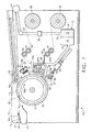
- Figure 1 is a schematic cross-sectional side view of one embodiment of a thermal development apparatus that includes a means for oxidizing vapor generated by heating a photosensitive element.
- The present invention relates to a process and apparatus for treating a photosensitive element. In particular the invention relates to a process and apparatus for thermally treating a photosensitive element containing a composition layer capable of being partially liquefied. The composition layer is heated to a temperature sufficient to melt at least a portion of the layer and generate vapor. Particularly, the present invention is a process and apparatus for oxidizing vapor that is generated during thermal treating of the photosensitive element. In one embodiment, the photosensitive element forms a flexographic printing form after treating.
- Thermal treating heats the photosensitive element to a development temperature that causes uncured portions of the composition layer to liquefy, i.e., melt or soften or flow, and be carried away by contact with an absorbent material. Cured portions of the photosensitive layer have a higher melting temperature than the uncured portions and therefore do not melt, soften, or flow at the thermal development temperatures. Thermal development of photosensitive elements to form flexographic printing plates is described in
U.S. 5,015,556 ;U.S. 5,175,072 ;U.S. 5,215,859 ; andWO 98/13730 - The term "melt" is used to describe the behavior of the unirradiated portions of the composition layer subjected to an elevated temperature that softens and reduces the viscosity to permit absorption by the absorbent material. The material of the meltable portion of the composition layer is usually a viscoelastic material which does not have a sharp transition between a solid and a liquid, so the process functions to absorb the heated composition layer at any temperature above some threshold for absorption in the absorbent material. A wide temperature range may be utilized to "melt" the composition layer for the purposes of this invention. Absorption may be slower at lower temperatures and faster at higher temperatures during successful operation of the process. Similarly, there may be less vaporization of components in the photosensitive layer at lower development temperatures and greater vaporization (which can be characterized by the amount of vapor formed and/or in the number of components that vaporize) at higher development temperatures.
- Apparatuses suitable for thermally developing or treating the photosensitive element are disclosed by
Peterson et al. in US Patent 5,279,697 , and byJohnson et al. in US Patent 6,797,454 . Although these patents depict that the photosensitive element is preferably placed on a drum for thermal treatment, it should be understood that the element could be placed on a planar surface, or on a combination of planar surface/s and roll/s, such as a belt supported system, for treatment. It should also be understood that one of ordinary skill in the art could modify the disclosed apparatus to accommodate mounting of the photosensitive element in the form of a cylinder or a sleeve on the drum, or two or more support rollers, or a suitable support structure. Another apparatus suitable for thermally developing a cylindrically-shaped photosensitive element is described in toU.S. patent application serial number 11/269096 filed November 8, 2005 - Thermal treating, which may also be called thermal development, includes heating of an
exterior surface 17 of the composition layer of thephotosensitive element 16 to a temperature sufficient to cause a portion of the layer to liquefy. The at least one photosensitive layer (and additional layer/s if present) can be heated by conduction, convection, radiation or other heating methods to a temperature sufficient to effect melting of the uncured portions but not so high as to effect distortion of the cured portions of the layer. One or more additional layers disposed above the composition layer may soften or melt or flow and be absorbed as well by an absorbent material. The photosensitive element is heated to a surface temperature above about 40°C, preferably from about 40°C to about 230°C (104-446 °F) in order to effect melting or flowing of the uncured portions of the composition layer. The thermal treating steps of heating thephotosensitive element 16 and contacting an outermost surface of the element with an absorbent material can be done at the same time, or in sequence provided that the uncured portions of the photopolymerizable layer are still soft or in a melt state when contacted with the absorbent material. - Figure 1 shows an embodiment of a
thermal processor 10. Adrum 18 is mounted for rotation on a stationary support frame12 and rotates in a clockwise direction as indicated by arrow 18a. Aphotosensitive element 16 is placed on asurface 13 offeed tray 14 and is urged in a direction indicated by arrow 14a. Thedrum 18 includes aclamp 20 that captures a leading edge of thephotosensitive element 16 to mount theelement 16 onto the drum. Theelement 16 remains substantially in contact with anouter surface 22 of thedrum 18 during processing. - The
drum 18 may be equipped with aheater 24, which is provided to keep thephotosensitive element 16 at a stable starting temperature independent of the surrounding environment. Any means of heating thedrum 18 is acceptable, as long as the power capacity of the heater is sufficient to maintain a fairly constant selected skin temperature on theouter surface 22 of thedrum 18 of about 50-150 °F (10-65.6 °C), preferably 65 to 95 °F (18.3-35 °C). The means for heating the drum is capable of heating thedrum 18 to a temperature capable of heating theexterior surface 17 of the composition layer. Theheater 24 may be an electrical heating blanket, such as a wire wound blanket. If the normal operating environment is carefully controlled to be at a constant temperature, the heater can be turned off or omitted from the apparatus. As is disclosed inUS Patent 6,797,454 , it is also possible that the drum be cooled by cooling means, such as, a blower directing a stream of air at the surface of the photosensitive element and the drum and/or by the circulating of cooling fluid beneath the surface of the drum to cool the support side of the element. - Located adjacent the
drum 18 is a first heating means comprising aheater 30 which, in the embodiment illustrated, is a radiant heater directed at anexterior surface 17 of thephotosensitive element 16 on thedrum 18. Theheater 30 can provide focused or diffused radiant heat. Theheater 30 elevates the temperature of theexterior surface 17 of the composition layer. In one embodiment, theheater 30 elevates the temperature of thesurface 17 of the composition layer to a temperature sufficient to melt the unirradiated portion of the composition layer, causing a portion of the layer to liquefy. Theheater 30 is a type of heater that does not appreciably heat the substrate supporting the composition layer. Theheater 30 applies heat to theexterior surface 17 of the composition layer. In the embodiment illustrated, theheater 30 comprises a plurality of tubular infrared heating bulbs, such asbulbs 31 mounted in end supports, such assupport 32 that also provide electrical connections to thebulbs 31. Adjacent the side of thebulbs 31opposite drum 18 is areflector 33 that acts to direct the infrared radiation toward theexterior surface 17 of thephotosensitive element sheet 16. An alternate embodiment of theheater 30 uses one tubularinfrared heating bulb 31 mounted in the end supports 32 with thereflector 33. - In the embodiment shown, the
processor 10 includes a delivery means for feeding acontinuous web 35 of a development medium, which contacts ahot roller 38. A second means for heating includes thehot roller 38. Thehot roller 38 is positioned adjacent thedrum 18 which carries thephotosensitive element 16. Thehot roller 38 is also adjacent theheater 30, and thehot roller 38 maintains or further elevates the temperature of theexterior surface 17 of the composition layer. Thehot roller 38 applies heat to theexterior surface 17 of thephotosensitive element 16. Theweb 35 of the development medium is unwound from asupply roll 40 and passes betweenrolls web 35 is then guided over thehot roller 38 and overrolls rolls web 35. One or more of therolls web 35 is then wound up on take uproll 45. - The
processor 10 is provided with a means for relative motion between thedrum 18 and thehot roller 38, so that thephotosensitive element 16 and theweb 35 of absorbent material can be brought into contact with the other. Means for providing relative movement can be accomplished, for example, by mounting the hot roller 38 (and/or drum 18) ontoarms 47 attached to abeam 48 that moves thehot roller 38 under the urging of one ormore actuators 49. Temperature sensors may be mounted throughout the processor to monitor the temperature for the purpose of controlling the heating elements in thedrum 18,hot roller 38, andradiant heater 30. - The
radiant heater 30 acting as a first heating means, thehot roller 38 acting as a second heating means, and thedrum heater 24 acting as a third heating means, independently or in any combination, are capable of heating theexterior surface 17 of thephotosensitive element 16 to a temperature sufficient to cause a portion, i.e., an unirradiated portion, of the composition layer to liquefy. The first heating means, the second heating means, and the third heating means independently or in any combination constitute aheating station 50. Apreferred heating station 50 includes the first heating means and the second heating means. - Heating the composition layer to a temperature sufficient to cause a portion of the layer to liquefy can also cause one or more components in the layer to form a vapor. The vapor formed by heating of the photosensitive element is composed primarily of organic compounds, such as monomer or monomers, in the composition layer. The vapor can also be formed from volatilization of other low molecular weight organic compounds that are present in the composition layer. In addition, it is possible that one or more components from additional layers on the composition layer may volatilize upon heating that are included in the vapor. The temperature of the vapor is at least the temperature at which thermal development occurs, that is between 40-230°C.
- Oxidizing of the vapor can be by a thermal or a catalytic process. Both oxidation processes convert the organic compounds in the vapor into innocuous components such as carbon dioxide and water vapor. Oxidation processes avoid forming a liquid waste stream that would require handling for disposal. Thermal oxidizing processes typically involve directing the vapor to burn with an open flame supplied by a fuel. Catalytic oxidation processes typically involve heating the vapor and passing the heated vapor across a catalyst to oxidize the organic compounds. The catalyst material is capable of oxidizing a number of organic substances to carbon dioxide and water at catalyst surface temperatures of at least 150°C. Heating to an elevated temperature also vaporizes any liquid droplets that are contained in the exhaust. It is expected that at least 90%, preferably at least 95%, of the organic compounds are converted to innocuous components. Trace amounts of organic compounds may be present in the air (vapor) resulting from the catalytic oxidation process. Oxidation can remove the organic compounds in the vapor to such an extent that handling of the air downstream of the processor (i.e., oxidation treatment) is not impacted by any remaining trace amounts of organic compounds. Catalytic oxidation is a preferred oxidation process for safety, economics, ease of use, and reduced concern for generating unwanted byproducts (such as for example, nitrogen oxides).
- One embodiment for oxidizing the vapor is with catalytic oxidation. The vapor can be heated to any temperature suitable for the catalytic oxidation reaction to occur. The temperature of the vapor can be at the temperature at which thermal development occurs, that is between 40-230°C, prior to entering an oxidation unit. In one embodiment, the temperature of the vapor entering the oxidation unit can be such that the vapor does not need to be additionally heated for catalytic oxidation to occur. Depending at least on the residence time in the processor and/or in a collection member prior to entering the oxidation unit, and the distance of the unit from the processor, the temperature of the vapor may be the same or substantially the same as the development temperature, or more likely has cooled below the development temperature. In one embodiment, the vapor is heated for catalytic oxidation to at least the temperature at which the organic compound or compounds volatize. In another embodiment, the vapor is heated for catalytic oxidation to a temperature above the temperature at which the organic compounds volatize. In another embodiment, the vapor is heated for catalytic oxidation to a temperature substantially above the temperature at which the organic compound or compounds volatize.
- The vapor is heated to a temperature at which the catalyst material is capable of oxidizing the organic compounds contained in the vapor. In one embodiment, the vapor may be heated to at least 150°C for catalytic oxidation. In one embodiment, the vapor may be heated to greater than 200°C for catalytic oxidation. In another embodiment, the vapor may be heated to at least 300°C for catalytic oxidation. In one embodiment, the vapor is heated to about 315 to 340°C. In one embodiment, the vapor may be heated to 650°C for catalytic oxidation. Although catalytic oxidation can occur at low temperatures, for example at temperatures less than 300°C, these low temperature oxidation systems generally are cost prohibitive and may not provide the desired efficiency to remove the organic compounds. Oftentimes the catalyst material is effective within a temperature range, and elevating the temperature of the vapor to the high end of the temperature range may be necessary for effective removal of various organic compound or compounds. However in order to conserve energy and operational costs, it is preferable to operate near (but above) the minimum temperature necessary for effective catalytic oxidation of the one or more organic compounds.
- In one embodiment, oxidization of the vapor occurs in a
container 70 provided with a means for heating the vapor and catalytic oxidation material. As shown in Figure 1, the container may be located inside thethermal development apparatus 10. Alternatively the container may be located external to the apparatus. Thecontainer 70 includes at least onechamber 71 having at least oneentry port 72 for the vapor and containing the means for heating the vapor (not shown), followed by anotherchamber 74 containing thecatalyst material 75 and having anexit port 76 for air that has been purified (which hereinafter may be referred to as purified air). It should be understood that the purified air contains carbon dioxide and water vapor, and may contain trace amounts of one or more organic compounds. The means for heating the vapor in the catalytic oxidizer container is not limited and can include electric heating coil, injection of heated gases, a flame, or other exothermic chemical reactions, or by transfer with a heat exchange fluid, or combinations thereof. The vapor is pulled into thecontainer 70 by a means for transporting the vapor, such as a blower or fan. The means for transporting may be included at theexit port 76 of thecontainer 70. Alternatively the means for transporting, such as avacuum fan 78 shown in Figure 1, may be outside thecontainer 70 interspersed in aconduit 62 from theexit port 76 to anexhaust port 54 for the purified air. The means for transporting the vapor may also be considered a means for collecting the vapor from the processor. Theoxidation container 70, the means for heating the vapor, and the means for transporting the vapor across the catalyst material and through at least the container constitute an oxidation system assembly. -
Suitable catalyst material 75 may be a noble metal oxidation catalyst selected from the group consisting of gold, silver, platinum, palladium, iridium, rhodium, mercury, ruthenium and/or osmium. Catalysts that contain gold, silver, platinum and/or palladium are preferred. The catalyst material may be supported on a metal substrate, or ceramic substrate, or an inert, porous support, such as potassium aluminum silicate. Typically catalyst material is in fine granular form and supported on a substrate to maximize the surface area available for reaction with components in the gas phase. Johnson Matthey (Wayne, PA) and Engelhard (Iselin, NJ) are suppliers of suitable oxidation catalyst materials. - Depending upon the type of catalyst used in a catalytic oxidation system, there are materials that can deactivate the catalyst either temporarily or permanently. Care should be taken to avoid the use of these materials in the photosensitive element composition and/or the creation of these materials by thermal treatment of the photosensitive element. Fortunately, the components typically used in photosensitive elements for flexographic printing are not usually the materials of concern. For example, the use of a noble metal catalyst is discouraged if the vapor may contain components such as sulfur, chlorine, or silicon. The catalyst supplier should provide guidance for a catalyst suitable for a particular composition of the photosensitive element.
- The purified air leaving the catalyst surface can exit the
container 70 and be exhausted fromprocessor 10 or from the operation area. Oxidization of the vapor results in purified air containing at least carbon dioxide and water vapor in amounts greater than that found in the ambient air. The purified air can be dispersed to a room or workspace where theprocessor 10 is located, usually with suitable thermal treatment to avoid overheating the workspace. The purified air can also be returned to theprocessor 10. Optionally, in one embodiment the purified air can be cooled with a simple heat exchanger (not shown) with outside ambient air circulation. Optionally in another embodiment, a heat exchanger can be used to cool the purified air and to heat the vapor prior to the entry of the vapor in theoxidation container 70. In this embodiment, the heat exchanger thus can act as a means for preheating the vapor prior to oxidation. This embodiment also has the advantage of reducing the accumulation of heat in the apparatus and/or the operating environment. - In one embodiment, all or a substantial portion of the vapor formed is treated to oxidize all the organic compounds and purify the resulting air stream. Air from within the
apparatus 10 may also be captured with the vapor that enters theoxidation container 70. Inclusion of the air with the vapor does not interfere with oxidation of the organic compounds in the vapor. However, the additional volume of air could need to be heated prior to oxidation of the vapor, which would increase the operational cost of the oxidation system. It may be desirable to minimize the volume of non-contaminated air that is captured and handled by the oxidation system assembly, so as to mitigate the additional cost. - The apparatus may include a means for collecting the vapor at or adjacent where the vapor is generated, before the vapor is diluted by the air that does not having any organic contaminants. Additionally or alternatively, the apparatus may include a means to isolate the vapor from the air in the surrounding environment of the apparatus to reduce the volume of air necessary to collect all or substantially all the vapor. The means for transporting (e.g., vacuum fan) the vapor also would need to be sized accordingly to transport the additional volume of air through the container. In one embodiment (not shown), the entry port of the oxidation container may be connected to an exhaust port of the apparatus. In another embodiment (not shown) where the oxidation container is located within the apparatus, the entry port of the container may be located in proximity to the heating station. The location of the oxidation system and its proximity to heating station do not necessarily influence the effectiveness of the oxidation system at removing the organic materials from the vapor, but can aid in the collection and/or isolation of the vapor and reduce the capture of additional non-vapor laden air (i.e., clean air). For example, in an embodiment that does not include the means for collecting vapor or the means for isolating the vapor, the closer the entry port of the container is to the heating station where the vapor is created, the more effectively the vapor will be directed to or captured by the oxidation system at a given exhaust flow rate or effective collection can be achieved with a lower total exhaust flow. In another embodiment, a means for isolating the vapor from the clean air in the processor is to entrain the vapor in a moving air stream directed toward a collection system or the oxidation system. Thus, if the collection system is not physically close to the heating station where the vapors are generated, the entrained air flow can function to extend the collection system to induce collection and hence capture the vapor entrained in the moving air.
- In one optional embodiment the vapor formed at the
heating station 50 during thermal development is collected at or near the location where the vapor is generated, that is, at the heating station, in order minimize the impact of vapor on other surfaces within the apparatus. By collecting the vapor at theheating station 50, the constituents of the vapor or any condensate do not disturb the relief surfaces of the photosensitive element currently being developed as well as the photosensitive elements that subsequently enter the process. Collecting and containing the vapor formed during thermal development will also improve the cleanliness and operation of the thermal processor. In addition, the collection of the vapor at the heating station reduces the volume of non-contaminated air captured by the oxidation system. - The vapor can be collected at or adjacent to where the
photosensitive element 16 is being heated at theheating station 50. The means for collecting the vapor collects the vapor as the vapor emits from the composition layer of thephotosensitive element 16. The means for collecting the vapor can include at least onecollection member 55, such as a manifold. Thecollection member 55 is positioned at theheating station 50 to collect as much of the vapor as it forms, and as such can be positioned anyplace in a region in and surrounding theheating station 50. Since vapor is most likely to form when the composition layer is reaching or reaches the temperature to liquefy, the at least onecollection member 55 is placed at or adjacent to a nip 60 where theexterior surface 17 of thephotosensitive element 16 contacts thedevelopment medium 35. The at least onecollection member 55 is adjacent to thehot roller 38 and thedrum 18. The at least onecollection member 55 is supported in theprocessor 10 by mounting brackets secured to theframe 12 or a side wall or an interior wall of theprocessor 10. The at least onecollection member 55 can be stationary or can move with thehot roller 38 when theroller 38 is urged toward thedrum 18. - There may be one or
more collection members 55 at theheating station 50 that are spaced about thehot roller 38 and even theheater 30. At least onecollection member 55 may be located on each side of thenip 60. The at least onecollection member 55 is the same or substantially the same axial length as thehot roller 38. The at least onecollection member 55 is a tube having a plurality ofopenings 55a or one or more axial slots for taking in the air containing the vapor. The vapor can be drawn into the at least one collectingmember 55 by thevacuum fan 78 that is ultimately connected to the means for oxidizing the vapor, or by another vacuum fan associated with the means for collecting. Thevacuum fan 78 can be turned on when the processor begins operation, and would remain on through the development, i.e., for the total number of cycles of heating and contacting, of thephotosensitive element 16. The fan may also run, preferably at low speed, during idle periods to capture any vapor from heating or maintaining the standby temperature inside the processor. - The means for isolating the vapor can include one or more shrouds, baffles, brushes or other structures or devices that can be appropriately positioned about the heating station to isolate and/or contain the vapor and reduce the amount of additional air (i.e., non-vapor laden air) collected with the vapor for oxidation. The means for isolating creates an enclosure of sorts about the heating station that minimizes the transfer of vapor to and air from the surrounding environment, while providing gaps necessary for the photosensitive element and the development medium move through the heating station.
- Optionally, the
apparatus 10 can include at least oneshroud 56 that isolates or substantially isolates the air with the vapor at theheating station 50 region from the remainder of the interior environment of theprocessor 10. Theshroud 56 is located on a backside of thehot roller 38 opposite thedrum 18 to substantially enclose the at least onecollection member 55 at theheating station 50. Theshroud 56 helps to keep the air with the vapor in theheating station 50 region, so that the at least onecollection members 55 can collect the vapor before the vapor escapes to other environs of theprocessor 10. In the embodiment shown, anend 58 of theshroud 56 is extended along the path of theweb 35 after the web has contacted thehot roller 38. Thus theshroud 56 covers theweb 35 while the web is still hot and helps to isolate vapor as vapor can continue to emit from the uncured portions of the composition layer that are carried away in the web. In an alternate embodiment,multiple shrouds 56 could be placed around the at least onecollection members 55. In another alternate embodiment, a box-like shroud could be located around the collecting member ormembers 55, with openings to allow theabsorbent web 35 to enter and leave, and at the nip between thehot roller 38 and thedrum 18. - The means for isolating the vapor can also include a supply of air, which may also be called an air knife or an air curtain, that can serve to isolate the vapor from the processor environment. Optionally, the supply of air may be included at the
heating station 50, near or adjacent to the at least onecollection members 55. The supply of air can serve to contain and direct the vapor toward the at least onecollection members 55. As shown in Figure 1, the air curtain can be supplied using one or moretubular members 57 each of which parallels or substantially parallels theadjacent collection member 55. Thetubular members 57 each have a plurality of openings that supply the air to theheating station 50. Preferably, the air curtain supplies air via thetubular member 57 at each of thecollection members 55 located prior to and after thenip 60. The air supplied by the air curtain is typically less than 10% of the total air removed by the at least onecollection member 55, preferably less than 5%. Air can be supplied from any convenient source of pressurized air, such as, for example, a compressed air line, a dedicated blower, or a side stream from a larger blower. It is also contemplated that the supply of air can be provided by directing all or a small stream of the air purified by the oxidation process. In the embodiment where the vapor is entrained in a moving air stream to collect the vapor, the additional air flow can also create a flow field that confines the vapor to act as a means for isolating the vapor, and can lend to more effective capture of vapor. - In one embodiment, the alternate means for collecting the vapor captures all or a majority of the vapor as it is generated. It is possible that only some of the vapor may be collected in this embodiment and the remainder of the vapor removed with the
exhaust 54. Depending on the fraction of the vapor exiting with the exhaust, it may desirable to locate the oxidation system assembly downstream of all vapor collection points so that the maximum amount of vapor is treated. The optional means for isolating the vapor including the at least one shroud and the air curtain, the means for transporting the vapor, and the alternate means for collecting the vapor, can be used alone or in combinations of one or more to confine and/or capture the vapor and direct the vapor to the oxidation system.. The means for isolating the vapor, the means for transporting the vapor, and the alternate means for collecting the vapor, can alone or in combination constitute a means for collecting the vapor. - In the embodiment shown in Figure 1, a
first end 65 of all of thecollection members 55 each connect to one ormore conduits 66 and that direct the vapor from the collection member/s 55 to the means for oxidizing the vapor. The collected vapor is contained and directed through theconduits 66 to the means for oxidizing of the vapor. Thefirst end 65 of thecollection member 55 is connected to afirst conduit 67a which in turn is connected to asecond conduit 67b. In one embodiment, theconduit 67b connects to theentry port 72 of thecontainer 70. In an alternate embodiment, a second end of the collection member 55 (coming out of the plane of the processor cross-section) can similarly connect to a series ofinterconnected conduits 66 that direct the vapor from the collection member to theoxidation container 70. - After collection, while in the collection member/s 55 or in the
conduits 66, the vapor may cool or be cooled such that one or more of the components in the vapor condenses to a liquid or liquid-like form. If the vapor cools while in the collection member/s 55 and forms condensate, moving air carries the condensate to the means for oxidizing the vapor. In the embodiment shown, thefirst conduits 67a are connect to thesecond conduit 67b which is oriented vertically or substantially vertically so that, if the vapor condenses, the condensate flows under gravity toward the means for managing the removal of vapor. Cooling may occur naturally as the air with vapor is transported away from theheating station 50 through thecollection member 55 and theconduits 66. Usually condensed material will revaporize upon heating prior to the oxidation system assembly or in the first chamber of thecontainer 70. One of ordinary skill in the art would take suitable precautions to design the method for heating the feed stream for the oxidation assembly if liquid is likely to be present in the stream. - Alternatively, the vapor may be heated with for example, an electrical wire wrapped about one or more of the first and
second conduits conduits 66 directly to theexhaust 54, for treatment to oxidize the organic compounds in the container of the oxidation system assembly that is located external to theprocessor 10. In this embodiment it may be necessary to heat or insulate ductwork or an external conduit between the exhaust of the apparatus and the oxidation container in order to maintain the organic components in their vapor state for entry into the container. Alternatively, the vapor can be allowed to cool to the extent that the organic components condense prior to entry in the oxidation system assembly located external to the apparatus. However, in this case care should be taken that the ductwork or external conduit between the exhaust of the apparatus and the container is designed to transport (and drain) the accumulated liquid condensate to the oxidation system assembly. - The
processor 10 may also include a heat management system for controlling the heat generated by thermal development.Outlets 52 are positioned above theheat station 50 to direct heated air out of the interior of the processor but are sufficiently far removed to minimize the chance of capturing vapor into the heat management system. The heated air exits theprocessor 10 through theexhaust 54. - In another embodiment, the vapor may be pretreated to remove some or part of the organic compounds from the vapor, and then the pretreated vapor would undergo oxidation in order to remove or substantially remove the one or more organic compounds from the air prior to disbursement into ambient air. The vapor may be pretreated with a means for controlling the vapor, which can include one or a combination of a means for collecting the vapor, a means for containing the vapor, and a means for managing the removal of the vapor as disclosed by
Hackler et al. in US Publication 2005/0084791 A1 , published Apr. 21, 2005. Advantageously, the method and apparatus of the present invention provides a means for oxidizing the vapor containing one or more organic compounds that are generated in thermal development of a photosensitive element. The vapor and condensate generated by thermal development is heated and undergoes an oxidation process, preferably a catalytic oxidation process. The oxidation process converts the one or more organic compounds into carbon dioxide and water vapor that can then be safely exhausted by conventional means from the processor and the customer's shop, or even returned to the interior environment of the apparatus. - The present invention is not limited to the type of element that is thermally processed, provided that the element generates a vapor upon heating. In one embodiment, the element is a photosensitive element that includes a flexible substrate and a composition layer mounted on the substrate. The composition layer is at least one layer on the substrate capable of being partially liquefied. Preferably, the photosensitive element is an elastomeric printing element suitable for use as a flexographic printing form. The at least one layer on the substrate is preferably a photosensitive layer, and most preferably a photopolymerizable layer of an elastomeric composition wherein the photosensitive layer can be selectively cured by actinic radiation. As used herein, the term "photopolymerizable" encompasses systems which are photopolymerizable, photocrosslinkable, or both. In cases where the composition layer comprises more than one photosensitive layer on the flexible substrate, the composition of each of the photosensitive layers can be the same or different from any of the other photosensitive layers.
- The layer of the photosensitive composition is capable of partially liquefying upon thermal development. That is, during thermal development the uncured composition must soften or melt at a reasonable processing or developing temperature. Heating the exterior surface of the composition layer to a temperature sufficient to cause a portion of the layer to liquefy also can cause one or more components in the layer to form a vapor.
- The photosensitive layer includes at least one monomer and a photoinitiator, and optionally a binder. The at least one monomer is an addition-polymerizable ethylenically unsaturated compound with at least one terminal ethylenic group. Monomers that can be used in the photosensitive layer are well known in the art and include monofunctional acrylates and methacrylates, multifunctional acrylates and methacrylates, and polyacryloyl oligomers.
- The photoinitiator is a compound that generates free radicals upon exposure to actinic radiation. Any of the known classes of photoinitiators, particularly free radical photoinitiators such as quinones, benzophenones, benzoin ethers, aryl ketones, peroxides, biimidazoles, diaryliodoniums, triarylsulfoniums, and phosphoniums, and diazoniums, may be used. Alternatively, the photoinitiator may be a mixture of compounds, one of which provides the free radicals when caused to do so by a sensitizer activated by radiation.
- The optional binder is a preformed polymer that serves as a matrix for the monomer and photoinitiator prior to exposure and is a contributor to the physical properties of the photopolymer both before and after exposure. In one embodiment the optional binder is elastomeric. A nonlimiting example of an elastomeric binder is an A-B-A type block copolymer, where A represents a nonelastomeric block, preferably a vinyl polymer and most preferably polystyrene, and B represents an elastomeric block, preferably polybutadiene or polyisoprene. Other suitable photosensitive elastomers that may be used include polyurethane elastomers, such as those described in
U.S. Patent Nos. 5,015,556 and5,175, 072 . The monomer or mixture of monomers must be compatible with the binder to the extent that a clear, non-cloudy photosensitive layer is produced. - Additional additives to the photosensitive layer include colorants, processing aids, antioxidants, and antiozonants. Processing aids may be such things as low molecular weight polymers compatible with the elastomeric block copolymer. Antiozonants include hydrocarbon waxes, norbornenes, and vegetable oils. Suitable antioxidants include alkylated phenols, alkylated bisphenols, polymerized trimethyldihydroquinone, and dilauryl thiopropinoate.
- The photosensitive element may include one or more additional layers on the side of the photosensitive layer opposite the substrate, as is well known to those skilled in the art. Examples of additional layers include, but are not limited to, a release layer, a capping layer, an elastomeric layer, a laser radiation-sensitive layer (typically an infrared laser radiation sensitive layer), a barrier layer, and combinations thereof. The one or more additional layers preferably are removable, in whole or in part, by contact with an absorbent material in the range of acceptable developing temperatures for the photosensitive element used. The one or more additional layers may contain components that can vaporize under the conditions of thermal development. One or more of the additional other layers can cover or only partially cover the photosensitive composition layer. The materials suitable for use as the additional layers are conventional and are well known to those of ordinary skill in the art.
- The photosensitive element of the present invention may further include a temporary coversheet on top of the uppermost layer of the photosensitive element to protect the uppermost layer of the photosensitive element during storage and handling. Depending upon end use, the coversheet may or may not be removed prior to imaging, but is removed prior to development.
- The substrate is selected to be tear resistant and must have a fairly high melt point, for example, above the melt temperature of the composition layer formed on the substrate. The material for the substrate is not limited and can be selected from polymeric films, foams, fabrics, and metals. The substrate can be almost any polymeric material that forms films that are non-reactive and remain stable throughout the processing conditions.
- The substrate of the photosensitive element has a thickness of between about 0.01 mm and about 0.38 mm. The photopolymerizable composition layer is between about 0.35 mm and about 7.6 mm thick, with a preferred thickness of about 0.5 mm to 3.9 mm (20 to 155 mils).
- The photosensitive element is prepared for thermal development by imagewise exposing the element to actinic radiation. After imagewise exposure, the photosensitive element contains cured portions in the exposed areas of the radiation curable composition layer and uncured portions in the unexposed areas of the radiation curable composition layer. Imagewise exposure is carried out by exposing the photosensitive element through an image-bearing mask. The image-bearing mask may be a black and white transparency or negative containing the subject matter to be printed, or an in-situ mask formed with the laser radiation sensitive layer on the composition layer, or other means known in the art. On exposure, the transparent areas of the mask allow addition polymerization or crosslinking to take place, while the actinic radiation opaque areas remain uncrosslinked. Exposure is of sufficient duration to polymerize or crosslink the exposed areas down to the support or to a back exposed layer (floor). Imagewise exposure time is typically much longer than backflash time, and ranges from a few to tens of minutes.
- For direct-to-plate image formation as disclosed in
U.S. Patent 5,262,275 ;U.S. Patent 5,719,009 ; U. S.5,607,814 ;U.S. Patent No. 5,506,086 ;U.S. Patent 5,766,819 ;U.S. Patent 5,840,463 andEP 0 741 330 A1 the image-bearing mask is formed in-situ with the laser radiation sensitive layer using an infrared laser exposure engine. The imagewise laser exposure can be carried out using various types of infrared lasers, which emit in the range 750 to 20,000 nm, preferably in the range 780 to 2,000 nm. - Actinic radiation sources encompass the ultraviolet, visible and infrared wavelength regions. The suitability of a particular actinic radiation source is governed by the photosensitivity of the initiator and the at least one monomer used in preparing the flexographic printing plates from the photosensitive element. The preferred photosensitivity of most common flexographic printing plates are in the UV and deep visible area of the spectrum, as they afford better room-light stability. The portions of the composition layer that are exposed to radiation chemically cross-link and cure. The portions of the composition layer that are unirradiated (unexposed) are not cured and have a lower melting temperature than the cured irradiated portions. The imagewise exposed photosensitive element is then ready for heat development with the absorbent material to form a relief pattern.
- An overall back exposure, a so-called backflash exposure, may be conducted before or after the imagewise exposure to polymerize a predetermined thickness of the photopolymer layer adjacent the support. This polymerized portion of the photopolymer layer is designated a floor. The floor thickness varies with the time of exposure, exposure source, etc. This exposure may be done diffuse or directed. All radiation sources suitable for imagewise exposure may be used. The exposure is generally for 10 seconds to 30 minutes.
- Following overall exposure to UV radiation through the mask, the photosensitive printing element is thermally developed to remove unpolymerized areas in the photopolymerizable layer and thereby form a relief image. The thermal development step removes at least the photopolymerizable layer in the areas which were not exposed to actinic radiation, i.e., the unexposed areas or uncured areas, of the photopolymerizable layer. Except for the elastomeric capping layer, typically the additional layers that may be present on the photopolymerizable layer are removed or substantially removed from the polymerized areas of the photopolymerizable layer.
- The operation of one embodiment of the
apparatus 10 for the process of thermally developing the photosensitive element is described in reference to Figure 1. Theplate processor 10 is in a home position with thedrum 18 stationary with theclamp 20 positioned near the top of the drum adjacent thefeed tray 14. The operator places thephotosensitive element 16 onfeed tray 14. An operator then opensclamp 20 and engages the leadingedge 24 of theelement 16 inclamp 20. Thedrum heater 24 or theIR heater 30 may be used to preheat thedrum 18. The cartridge heater (not shown) for thehot roll 38 is used to preheat the hot roll. Thedrum 18 starts turning and carries theelement 16 with it. Theheater 30 may preheat thebulbs 31 before theelement 16 reaches theheater 30, and then switch to an operating setting to achieve the desired temperature for melting the composition layer onelement 16. As the leadingedge 24 of theelement 16 reaches the position where thehot roll 38 will contact thedrum 18, thehot roll actuators 49 move thehot roll 38 carrying theweb 35 of the development medium against theelement 16. The photosensitive element composition layer is heated to between 40 and 230°C. (104-392°F.) while in contact with the development medium. The development medium contacts theexterior surface 17 of the composition layer of the heated photosensitive element, and removes the liquefied portions of the elastomeric polymer from the unirradiated portions of the composition layer, forming a flexographic printing form in which portions are removed as shown to form a relief pattern or surface. By maintaining more or less intimate contact of the development medium with the composition layer that is molten in the uncured regions, a transfer of the uncured photosensitive material from the photopolymerizable layer to the development medium takes place. While still in the heated condition, the development medium is separated from the cured photosensitive element 16a to reveal the relief structure. At the same time as heating the photosensitive element, vapor is generated that contains one or more organic compounds from the composition layer (and/or other additional layers) or reaction or decomposition products thereof. Vapor is collected in the at least onecollection member 55 and transported byvacuum fan 78 throughconduits 66 to theentry port 72 of theoxidation container 70. The vapor is heated in thefirst chamber 71 of theoxidation container 70 to a temperature suitable for the oxidation catalyst to convert the one or more organic compounds in the vapor to carbon dioxide and water vapor. The heated vapor passes through asecond chamber 74 containing thecatalyst material 75 and exits theoxidation chamber 70 throughport 76 as purified air. Optionally the purified air can be sent through a heat exchanger, prior to exiting the processor through the exhaust. - As the trailing edge of the
element 16 passes the hot roll/drum contact point, i.e., nip, theheater 30 may cool down or turn off, theactuator 49 will retract thehot roll 38, and theweb 35 can be stopped. Thedrum 18 may return the leading edge of theelement 16 to the home position to begin another cycle of heating and contacting. A cycle of the steps of heating the photopolymerizable layer and contacting the molten (portions) layer with the development medium can be repeated as many times as necessary to adequately remove the uncured material and create sufficient relief depth. However, it is desirable to minimize the number of cycles for suitable system performance, and typically the photopolymerizable element is thermally treated for 5 to 15 cycles. Intimate contact of the development medium to the photopolymerizable layer (while in the uncured portions are melt) may be maintained by the pressing the layer and the development medium together. - The development medium is selected having a melt temperature exceeding the melt temperature of the unirradiated or uncured portions of the radiation curable composition and having good tear resistance at the same operating temperatures. Preferably, the selected medium withstands temperatures required to process the photosensitive element during heating. The development medium may also be referred to as an absorbent material. The development medium is selected from non-woven materials, paper stocks, fibrous woven material, open-celled foam materials, porous materials that contain more or less a substantial fraction of their included volume as void volume. The development medium can be in web or sheet form. The development medium should also possess a high absorbency for the molten elastomeric composition by milligrams of elastomeric composition that can be absorbed per square centimeter of the development medium. It is also desirable that fibers are bonded in an absorbent material so that the fibers are not deposited into the plate during development. Non-woven webs of nylon or polyester are preferred.
- After thermal development, the flexographic printing form may be post exposed and/or chemically or physically after-treated in any sequence to detackify the surface of the flexographic printing form.
Claims (65)
- A method for forming a relief pattern from a photosensitive element containing a composition layer capable of being partially liquefied, comprising:heating the composition layer to a temperature sufficient to cause a portion of the layer to liquefy and cause one or more organic compounds in the layer to form a vapor; andoxidizing the vapor.
- The method of Claim 1 wherein oxidizing comprises converting the one or more organic compounds to carbon dioxide and water vapor.
- The method of Claim 1 wherein the oxidizing is by catalytic oxidation.
- The method of Claim 1 wherein the oxidizing is by thermal oxidation.
- The method of Claim 1 further comprising collecting the vapor.
- The method of Claim 5 wherein the collecting the vapor is at a heating station at or adjacent to the heating of the composition layer.
- The method of Claim 1 further comprising contacting the photosensitive element with a development medium to remove at least a portion of the liquefied material by the development medium.
- The method of Claim 7 wherein the contacting is pressing the photosensitive element and the development medium into contact at a pressure sufficient for at least a portion of the liquefied material to be removed by the development medium.
- The method of Claim 7 further comprising separating the photosensitive element from the development medium.
- The method of Claim 7 further comprising collecting the vapor at a heating station at or adjacent to the contacting with the development medium.
- The method of Claim 1 further comprising
supplying a development medium to an exterior surface of the composition layer; and
supporting the photosensitive element. - The method of Claim 1 wherein the composition layer has an exterior surface, and the heating is selected from the group consisting of
a first heating to apply heat to the exterior surface of the composition layer adjacent where a development medium contacts the layer;
a seco nd heating to heat a first member supplying the development medium to a temperature capable of heating the exterior surface of the composition layer while the development medium is contacting the exterior surface of the layer;
a third heating to heat a second member supporting the photosensitive element to a temperature capable of heating the exterior surface of the composition layer;
a combination of the first heating and the second heating;
a combination of the first heating and the third heating;
a combination of the second heating and the third heating; and
a combination of the first heating, the second heating and the third heating. - The method of Claim 1 further comprising heating the vapor to a temperature of at least 150°C prior to oxidizing.
- The method of Claim 1 further comprising heating the vapor to a temperature between 200 and 650 °C prior to oxidizing.
- The method of Claim 1 further comprising heating the vapor to a temperature of at least 300°C prior to oxidizing.
- The method of Claim 1 further comprising heating the vapor to a temperature of about 315 to 340°C prior to oxidizing.
- The method of Claim 1 wherein oxidizing the vapor results in purified air comprising at least carbon dioxide and water vapor.
- The method of Claim 17 further comprising cooling the purified air.
- The method of Claim 17 further comprising preheating the vapor and cooling the purified air by transporting vapor and purified air through a heat exchanger.
- The method of Claim 17 further comprising supplying all or a portion of the purified air to a heating station.
- The method of Claim 1 further comprising preheating the vapor.
- The method of Claim 1 further comprising maintaining the vapor at a temperature sufficient to keep the vapor in its vaporized state for oxidation.
- The method of Claim 1 further comprising isolating the vapor at a heating station.
- The method of Claim 23 wherein the isolating the vapor is by positioning at least one structure selected from the group consisting of shroud, baffle and brush about the heating station
- The method of Claim 23 wherein the isolating the vapor is by supplying a curtain of air at the heating station.
- The method of Claim 1 further comprising means for transporting the vapor to the oxidizing step.
- The method of Claim 1 wherein the oxidizing is by catalytic oxidation using a catalyst material selected from the group consisting of gold, silver, platinum, palladium, iridium, rhodium, mercury, ruthenium, osmium, and combinations thereof.
- The method of Claim 1 further comprising
imagewise exposing the photosensitive element to actinic radiation prior to heating; and
contacting the photosensitive element with a development medium to allow at least a portion of the liquefied material of the composition layer to be removed by the development medium to form the relief pattern. - A flexographic printing form prepared according to the method of Claim 28.
- An apparatus for forming a relief pattern from a photosensitive element containing a composition layer capable of being partially liquefied, comprising:means for heating the composition layer to a temperature sufficient to cause a portion of the layer to liquefy and cause one or more compounds in the layer to form a vapor; andmeans for oxidizing the vapor.
- The apparatus of Claim 30 wherein the means for oxidizing comprises means for passing the vapor across a catalyst material to convert the at least one organic compound into carbon dioxide and water.
- The apparatus of Claim 30 wherein the means for oxidizing comprises means for passing the vapor across a catalyst material selected from the group consisting of gold, silver, platinum, palladium, iridium, rhodium, mercury, ruthenium, osmium, and combinations thereof.
- The apparatus of Claim 30 further comprising means for collecting the vapor.
- The apparatus of Claim 33 wherein the means for collecting the vapor is at a heating station at or adjacent to the means for heating.
- The apparatus of Claim 33 wherein the means for collecting the vapor comprises at least one manifold.
- The apparatus of Claim 33 wherein the means for collecting the vapor is a blower or a fan.
- The apparatus of Claim 30 further comprising means for contacting the photosensitive element with a development medium to remove at least a portion of the liquefied material by the development medium.
- The apparatus of Claim 37 further comprising means for pressing the photosensitive element and the development medium into contact at a pressure sufficient for at least a portion of the liquefied material to be removed.
- The apparatus of Claim 37 further comprising means for separating the photosensitive element from the development medium.
- The apparatus of Claim 37 further comprising means for collecting the vapor at a heating station at or adjacent to the means for contacting with the development medium.
- The apparatus of Claim 30 further comprising:means for supplying the development medium to an exterior surface of the composition layer;means for supporting the photosensitive element, wherein at least one of the means for supplying and the means for supporting are movable relative to the other.
- The apparatus of Claim 41 wherein the composition layer has an exterior surface, and the means for heating is selected from the group consisting of
a first heating means for applying heat to the exterior surface of the composition layer adjacent where a development medium contacts the layer;
a second heating means for heating the supplying means to a temperature capable of heating the exterior surface of the composition layer while the development medium is contacting the exterior surface of the layer;
a third heating means for heating the supporting means to a temperature capable of heating the exterior surface of the composition layer;
a combination of the first heating means and the second heating means;
a combination of the first heating means and the third heating means;
a combination of the second heating means and third heating means; and
a combination of the first heating means, the second heating means, and the third heating means. - The apparatus of Claim 41 wherein the means for supplying the development medium comprises a roller mounted for rotation in a first frame portion.
- The apparatus of Claim 41 the means for supporting comprises a drum mounted for rotation in a second frame portion, the drum having an outer circumferential surface adapted to support the photosensitive element.
- The apparatus of Claim 30 wherein the means for oxidizing comprises:an oxidation system assembly comprising a container, a means for heating the vapor in a first chamber of the container, and a means for transporting the vapor across a catalyst material in a second chamber of the container.
- The apparatus of Claim 45 wherein the means for heating the vapor is an electric coil.
- The apparatus of Claim 45 wherein the means for heating the vapor heats the vapor to a temperature between 150 and 650°C.
- The apparatus of Claim 45 wherein the means for heating the vapor heats the vapor to a temperature of at least 300°C.
- The apparatus of Claim 45 wherein the means for heating the vapor heats the vapor to a temperature of about 315 to 340°C prior to oxidizing.
- The apparatus of Claim 45 wherein the means for transporting the vapor is a vacuum fan.
- The apparatus of Claim 30 wherein the means for oxidizing comprises: an oxidation container comprising a first chamber having an electric coil for heating the vapor, and a second chamber containing a catalyst material.
- The apparatus of Claim 30 wherein the means for oxidizing provides purified air comprising at least carbon dioxide and water vapor.
- The apparatus of Claim 52 further comprising means for cooling the purified air.
- The apparatus of Claim 52 further comprising a heat exchanger for preheating the vapor and cooling the purified air.
- The apparatus of Claim 52 further comprising means for supplying all or a portion of the purified air to or adjacent to a heating station..
- The apparatus of Claim 30 further comprising means for preheating the vapor.
- The apparatus of Claim 30 further comprising means for maintaining the vapor at a temperature sufficient to keep the vapor in its vaporized state for oxidation.
- The apparatus of Claim 30 further comprising means for isolating the vapor at or adjacent to the means for heating the composition.
- The apparatus of Claim 58 wherein the means for isolating the vapor comprises one or more shrouds placed about a heating station.
- The apparatus of Claim 30 further comprising means for supplying air at or adjacent to a heating station.
- The apparatus of Claim 30 further comprising means for transporting the vapor to the means for oxidizing.
- The apparatus of Claim 30 further comprising means for transporting the vapor to the means for oxidizing, means for collecting the vapor, and means for isolating the vapor at a heating station.
- The apparatus of Claim 30 wherein the means for oxidizing is located internal to the apparatus.
- The apparatus of Claim 30 wherein the means for oxidizing is located external to the apparatus.
- The apparatus of Claim 64 further comprising means for maintaining the vapor in its vaporized state for entry to the means for oxidizing.
Applications Claiming Priority (1)
| Application Number | Priority Date | Filing Date | Title |
|---|---|---|---|
| US11/409,609 US7491003B2 (en) | 2006-04-24 | 2006-04-24 | Method and apparatus for thermal development with vapor treatment |
Publications (3)
| Publication Number | Publication Date |
|---|---|
| EP1850183A2 true EP1850183A2 (en) | 2007-10-31 |
| EP1850183A3 EP1850183A3 (en) | 2011-03-16 |
| EP1850183B1 EP1850183B1 (en) | 2015-12-30 |
Family
ID=38069377
Family Applications (1)
| Application Number | Title | Priority Date | Filing Date |
|---|---|---|---|
| EP07007694.8A Active EP1850183B1 (en) | 2006-04-24 | 2007-04-16 | Method and apparatus for thermal development with vapor treatment |
Country Status (3)
| Country | Link |
|---|---|
| US (1) | US7491003B2 (en) |
| EP (1) | EP1850183B1 (en) |
| JP (2) | JP2007316621A (en) |
Cited By (1)
| Publication number | Priority date | Publication date | Assignee | Title |
|---|---|---|---|---|
| EP2128705A3 (en) * | 2008-05-27 | 2010-06-30 | E. I. du Pont de Nemours and Company | Apparatus and method for treating a cylindrically-shaped element using a clamp assembly |
Families Citing this family (4)
| Publication number | Priority date | Publication date | Assignee | Title |
|---|---|---|---|---|
| US7398812B2 (en) * | 2003-12-31 | 2008-07-15 | E.I. Du Pont De Nemours And Company | Apparatus for thermal development having a removable support member |
| GB0803670D0 (en) * | 2008-02-28 | 2008-04-09 | Johnson Matthey Plc | Improvements in emission control |
| US8359975B2 (en) * | 2008-05-23 | 2013-01-29 | E.I. Du Pont De Nemours And Company | Process and apparatus having an adjustable heater |
| US9032877B2 (en) * | 2011-11-02 | 2015-05-19 | E I Du Pont De Nemours And Company | Method and an apparatus having a compressible collar for thermally treating a photosensitive precursor |
Citations (4)
| Publication number | Priority date | Publication date | Assignee | Title |
|---|---|---|---|---|
| EP1526410A1 (en) * | 2003-10-16 | 2005-04-27 | E.I. Du Pont De Nemours And Company | Method and apparatus for thermal development |
| WO2005061231A1 (en) * | 2003-11-27 | 2005-07-07 | Xsys Print Solutions Deutschland Gmbh | Method for producing flexographic printing plates by means of laser engraving |
| US20050238381A1 (en) * | 2004-04-27 | 2005-10-27 | Samsung Electronics Co., Ltd. | Oxidation catalyst unit, a controlling method thereof, and a wet-type electrophotographic image forming apparatus comprising the oxidation catalyst unit |
| US20050241509A1 (en) * | 2004-04-30 | 2005-11-03 | Timothy Gotsick | System for thermal development of flexographic printing plates |
Family Cites Families (14)
| Publication number | Priority date | Publication date | Assignee | Title |
|---|---|---|---|---|
| NL287134A (en) * | 1959-08-05 | |||
| US3264103A (en) * | 1962-06-27 | 1966-08-02 | Du Pont | Photopolymerizable relief printing plates developed by dry thermal transfer |
| JPS5037282A (en) * | 1973-08-03 | 1975-04-07 | ||
| JPS567527U (en) * | 1979-06-27 | 1981-01-22 | ||
| JPS578557A (en) * | 1980-06-19 | 1982-01-16 | Ricoh Co Ltd | Treatment of waste gas from electrophotographic copying machine |
| US5175072A (en) * | 1990-07-26 | 1992-12-29 | Minnesota Mining And Manufacturing Company | Flexographic printing plate process |
| US5215859A (en) * | 1990-07-26 | 1993-06-01 | Minnesota Mining And Manufacturing Company | Backside ionizing irradiation in a flexographic printing plate process |
| US5015556A (en) * | 1990-07-26 | 1991-05-14 | Minnesota Mining And Manufacturing Company | Flexographic printing plate process |
| EP0469735B1 (en) | 1990-07-31 | 1998-06-10 | Minnesota Mining And Manufacturing Company | Device for forming flexographic printing plate |
| WO1998013730A1 (en) | 1996-09-27 | 1998-04-02 | Minnesota Mining And Manufacturing Company | Multilayer flexographic printing plate |
| US6797454B1 (en) * | 1999-09-07 | 2004-09-28 | E. I. Du Pont De Nemours And Company | Method and apparatus for thermal processing a photosensitive element |
| WO2001018604A2 (en) | 1999-09-07 | 2001-03-15 | E. I. Du Pont De Nemours And Company | Method and apparatus for thermal processing a photosensitive element |
| KR100476955B1 (en) * | 2002-12-03 | 2005-03-17 | 삼성전자주식회사 | gas discharging apparatus of an wet type electrophotography printer |
| US6998218B2 (en) * | 2004-03-29 | 2006-02-14 | Markhart Gary T | Apparatus and method for thermally developing flexographic printing sleeves |
-
2006
- 2006-04-24 US US11/409,609 patent/US7491003B2/en active Active
-
2007
- 2007-04-16 EP EP07007694.8A patent/EP1850183B1/en active Active
- 2007-04-23 JP JP2007113418A patent/JP2007316621A/en active Pending
-
2012
- 2012-07-03 JP JP2012149691A patent/JP2012194580A/en active Pending
Patent Citations (4)
| Publication number | Priority date | Publication date | Assignee | Title |
|---|---|---|---|---|
| EP1526410A1 (en) * | 2003-10-16 | 2005-04-27 | E.I. Du Pont De Nemours And Company | Method and apparatus for thermal development |
| WO2005061231A1 (en) * | 2003-11-27 | 2005-07-07 | Xsys Print Solutions Deutschland Gmbh | Method for producing flexographic printing plates by means of laser engraving |
| US20050238381A1 (en) * | 2004-04-27 | 2005-10-27 | Samsung Electronics Co., Ltd. | Oxidation catalyst unit, a controlling method thereof, and a wet-type electrophotographic image forming apparatus comprising the oxidation catalyst unit |
| US20050241509A1 (en) * | 2004-04-30 | 2005-11-03 | Timothy Gotsick | System for thermal development of flexographic printing plates |
Non-Patent Citations (1)
| Title |
|---|
| HAFERKAMP H ET AL: "ABLUEFTE AUS DER LASERBEARBEITUNG VON KUNSTSTOFFEN RICHTIG FILTRIEREN", LASER MAGAZIN, MAGAZIN VERLAG, BAD NENNDORF, DE, vol. 6, 1 January 1998 (1998-01-01), pages 6-11, XP009044300, ISSN: 0945-8875 * |
Cited By (1)
| Publication number | Priority date | Publication date | Assignee | Title |
|---|---|---|---|---|
| EP2128705A3 (en) * | 2008-05-27 | 2010-06-30 | E. I. du Pont de Nemours and Company | Apparatus and method for treating a cylindrically-shaped element using a clamp assembly |
Also Published As
| Publication number | Publication date |
|---|---|
| JP2012194580A (en) | 2012-10-11 |
| US7491003B2 (en) | 2009-02-17 |
| JP2007316621A (en) | 2007-12-06 |
| US20070248912A1 (en) | 2007-10-25 |
| EP1850183A3 (en) | 2011-03-16 |
| EP1850183B1 (en) | 2015-12-30 |
Similar Documents
| Publication | Publication Date | Title |
|---|---|---|
| US20090098491A1 (en) | Method and apparatus for thermal development | |
| EP1216436B1 (en) | Method and apparatus for thermal processing of a photosensitive element | |
| EP1850183B1 (en) | Method and apparatus for thermal development with vapor treatment | |
| EP1624344B1 (en) | Method and apparatus for thermal development with a non-rotating supporting surface for a development medium | |
| US7503258B2 (en) | Method and apparatus for thermal development with development medium remover | |
| EP2987033B1 (en) | An exposure apparatus and a method for controlling radiation from a lamp for exposing a photosensitive element | |
| US20070041741A1 (en) | Apparatus for the rapid development of photosensitive printing elements | |
| EP1553456B1 (en) | Method and apparatus for thermal development having a removable support member | |
| US11325369B2 (en) | System for thermal development of flexographic printing plates | |
| US11624983B2 (en) | Method and system for thermal processing of flexo printing elements | |
| WO2013067442A1 (en) | Method and apparatus for thermal treatment of printing surface in relief printing |
Legal Events
| Date | Code | Title | Description |
|---|---|---|---|
| PUAI | Public reference made under article 153(3) epc to a published international application that has entered the european phase |
Free format text: ORIGINAL CODE: 0009012 |
|
| AK | Designated contracting states |
Kind code of ref document: A2 Designated state(s): AT BE BG CH CY CZ DE DK EE ES FI FR GB GR HU IE IS IT LI LT LU LV MC MT NL PL PT RO SE SI SK TR |
|
| AX | Request for extension of the european patent |
Extension state: AL BA HR MK YU |
|
| PUAL | Search report despatched |
Free format text: ORIGINAL CODE: 0009013 |
|
| AK | Designated contracting states |
Kind code of ref document: A3 Designated state(s): AT BE BG CH CY CZ DE DK EE ES FI FR GB GR HU IE IS IT LI LT LU LV MC MT NL PL PT RO SE SI SK TR |
|
| AX | Request for extension of the european patent |
Extension state: AL BA HR MK RS |
|
| RIC1 | Information provided on ipc code assigned before grant |
Ipc: B01D 53/86 20060101ALI20110210BHEP Ipc: G03F 7/36 20060101AFI20070612BHEP |
|
| 17P | Request for examination filed |
Effective date: 20110914 |
|
| AKX | Designation fees paid |
Designated state(s): DE FR GB |
|
| 17Q | First examination report despatched |
Effective date: 20150107 |
|
| GRAP | Despatch of communication of intention to grant a patent |
Free format text: ORIGINAL CODE: EPIDOSNIGR1 |
|
| INTG | Intention to grant announced |
Effective date: 20150728 |
|
| GRAS | Grant fee paid |
Free format text: ORIGINAL CODE: EPIDOSNIGR3 |
|
| GRAA | (expected) grant |
Free format text: ORIGINAL CODE: 0009210 |
|
| AK | Designated contracting states |
Kind code of ref document: B1 Designated state(s): DE FR GB |
|
| REG | Reference to a national code |
Ref country code: GB Ref legal event code: FG4D |
|
| RAP2 | Party data changed (patent owner data changed or rights of a patent transferred) |
Owner name: E. I. DU PONT DE NEMOURS AND COMPANY |
|
| REG | Reference to a national code |
Ref country code: DE Ref legal event code: R096 Ref document number: 602007044348 Country of ref document: DE |
|
| REG | Reference to a national code |
Ref country code: FR Ref legal event code: PLFP Year of fee payment: 10 |
|
| REG | Reference to a national code |
Ref country code: DE Ref legal event code: R097 Ref document number: 602007044348 Country of ref document: DE |
|
| PLBE | No opposition filed within time limit |
Free format text: ORIGINAL CODE: 0009261 |
|
| STAA | Information on the status of an ep patent application or granted ep patent |
Free format text: STATUS: NO OPPOSITION FILED WITHIN TIME LIMIT |
|
| 26N | No opposition filed |
Effective date: 20161003 |
|
| REG | Reference to a national code |
Ref country code: FR Ref legal event code: PLFP Year of fee payment: 11 |
|
| REG | Reference to a national code |
Ref country code: FR Ref legal event code: PLFP Year of fee payment: 12 |
|
| REG | Reference to a national code |
Ref country code: DE Ref legal event code: R081 Ref document number: 602007044348 Country of ref document: DE Owner name: DUPONT ELECTRONICS, INC., WILMINGTON, US Free format text: FORMER OWNER: E.I. DU PONT DE NEMOURS AND CO., WILMINGTON, DEL., US |
|
| REG | Reference to a national code |
Ref country code: GB Ref legal event code: 732E Free format text: REGISTERED BETWEEN 20221020 AND 20221026 |
|
| PGFP | Annual fee paid to national office [announced via postgrant information from national office to epo] |
Ref country code: FR Payment date: 20230309 Year of fee payment: 17 |
|
| P01 | Opt-out of the competence of the unified patent court (upc) registered |
Effective date: 20230528 |
|
| PGFP | Annual fee paid to national office [announced via postgrant information from national office to epo] |
Ref country code: DE Payment date: 20230307 Year of fee payment: 17 |
|
| PGFP | Annual fee paid to national office [announced via postgrant information from national office to epo] |
Ref country code: GB Payment date: 20240229 Year of fee payment: 18 |