EP1849921A2 - Locking device for hydraulic attachment interface - Google Patents
Locking device for hydraulic attachment interface Download PDFInfo
- Publication number
- EP1849921A2 EP1849921A2 EP07251659A EP07251659A EP1849921A2 EP 1849921 A2 EP1849921 A2 EP 1849921A2 EP 07251659 A EP07251659 A EP 07251659A EP 07251659 A EP07251659 A EP 07251659A EP 1849921 A2 EP1849921 A2 EP 1849921A2
- Authority
- EP
- European Patent Office
- Prior art keywords
- hydraulic
- attachment
- mounting bracket
- interface
- engagement member
- Prior art date
- Legal status (The legal status is an assumption and is not a legal conclusion. Google has not performed a legal analysis and makes no representation as to the accuracy of the status listed.)
- Granted
Links
Images





Classifications
-
- E—FIXED CONSTRUCTIONS
- E02—HYDRAULIC ENGINEERING; FOUNDATIONS; SOIL SHIFTING
- E02F—DREDGING; SOIL-SHIFTING
- E02F3/00—Dredgers; Soil-shifting machines
- E02F3/04—Dredgers; Soil-shifting machines mechanically-driven
- E02F3/28—Dredgers; Soil-shifting machines mechanically-driven with digging tools mounted on a dipper- or bucket-arm, i.e. there is either one arm or a pair of arms, e.g. dippers, buckets
- E02F3/36—Component parts
- E02F3/3604—Devices to connect tools to arms, booms or the like
- E02F3/3609—Devices to connect tools to arms, booms or the like of the quick acting type, e.g. controlled from the operator seat
- E02F3/3631—Devices to connect tools to arms, booms or the like of the quick acting type, e.g. controlled from the operator seat with a hook and a transversal locking element
-
- E—FIXED CONSTRUCTIONS
- E02—HYDRAULIC ENGINEERING; FOUNDATIONS; SOIL SHIFTING
- E02F—DREDGING; SOIL-SHIFTING
- E02F3/00—Dredgers; Soil-shifting machines
- E02F3/04—Dredgers; Soil-shifting machines mechanically-driven
- E02F3/28—Dredgers; Soil-shifting machines mechanically-driven with digging tools mounted on a dipper- or bucket-arm, i.e. there is either one arm or a pair of arms, e.g. dippers, buckets
- E02F3/36—Component parts
- E02F3/3604—Devices to connect tools to arms, booms or the like
- E02F3/3609—Devices to connect tools to arms, booms or the like of the quick acting type, e.g. controlled from the operator seat
- E02F3/3636—Devices to connect tools to arms, booms or the like of the quick acting type, e.g. controlled from the operator seat using two or four movable transversal pins
-
- E—FIXED CONSTRUCTIONS
- E02—HYDRAULIC ENGINEERING; FOUNDATIONS; SOIL SHIFTING
- E02F—DREDGING; SOIL-SHIFTING
- E02F3/00—Dredgers; Soil-shifting machines
- E02F3/04—Dredgers; Soil-shifting machines mechanically-driven
- E02F3/28—Dredgers; Soil-shifting machines mechanically-driven with digging tools mounted on a dipper- or bucket-arm, i.e. there is either one arm or a pair of arms, e.g. dippers, buckets
- E02F3/36—Component parts
- E02F3/3604—Devices to connect tools to arms, booms or the like
- E02F3/3609—Devices to connect tools to arms, booms or the like of the quick acting type, e.g. controlled from the operator seat
- E02F3/3663—Devices to connect tools to arms, booms or the like of the quick acting type, e.g. controlled from the operator seat hydraulically-operated
Definitions
- the disclosed embodiments relate to interchangeable tool attachments such as buckets, grapples, hydraulic hammers, tampers, augers and the like used with a power operated arm of an implement such as an excavator or backhoe. More particularly, the embodiments relate to an attachment device that allows attachments to be quickly attached to the power operated arm.
- a pin 34 extends through both the cross link 32 and the excavator arm 18 to provide a pivotal attachment.
- a pin 30 at cylinder link pivot joint 28 pivotally attaches the cylinder rod 16 with both the cross link 32 and the cylinder link 26.
- Cylinder link 26 is pivotally attached to the quick attachment mount 22 at pivot 25, with a pin 27 extending through both the cylinder link 26 and the quick attachment mount 22.
- a fragmentary portion of an attachment 40 is partially engaged with the quick attachment mount 22 at pin 38.
- Attachment 40 includes an engagement region 44 which is adapted to engage with support region 46 of quick attachment mount 22 when the quick attachment mount is rotated about pin 38 in the direction of arrow 48. The attachment 40 is then secured to the quick attachment mount 22 at support region 46.
- Attachments of the type used with excavators or back hoes can have a pivotal rotation of approximately 270 degrees.
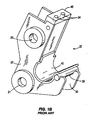
- FIG. 1B illustrates in more detail the prior art quick attachment mount 22.
- Quick attachment mount 22 includes a first side plate 50 and a second side plate 52.
- First side 50 and second side 52 each have a pair of apertures 21 and 23 formed through them in position such that when quick attachment mount 22 is positioned with respect to excavator arm is the aperture 21 in FIG. 1B aligns with the boom arm to create the boom arm pivot joint 20.
- the aperture 23 in FIG. 1B is aligned to engage cylinder link 26 to create pivot 25.
- First aide 50 and second aide 52 are also connected via a support region 46, a multi-surfaced crossmember that extends along an end of the each of the first and second sides
- attachment 40 engages pin 38 and is capable of rotating on pin 38 in either direction.
- the quick attachment mount 22 is rotated in position such that engagement region 44 is in connection with or is positioned adjacent support region 46, a portion of the attachment 40 is positioned adjacent to retainer or cradle 42.
- the cradle 42 serves to assist in holding the attachment in place with respect to the quick attachment mount 22.
- Support region 46 is positioned to engage and support the engagement region 44 of attachment 40 when the quick attachment mount 22 is rotated into position.
- the engagement region 44 has a pair of bores (not shown) that match up with a pair of bores 54 that extend through the engagement surface 46.
- a fastener arrangement such as a nut and bolt or a pin of some sort is extended through the aligned bores to fixedly attach the attachment to the attachment mount 22.
- an attachment mount that provides a quicker and easier method of attaching the attachment to the attachment mount.
- One embodiment is directed toward an hydraulic interface between a power machine having an hydraulic power system and an attachment mounting bracket having an hydraulically actuated engagement member.
- the hydraulic interface includes a first portion capable of being coupled to the hydraulic power system and a second portion fixedly attached to the attachment mounting bracket.
- the first portion is pivotally coupled to the second portion so that the attachment bracket is capable of pivoting with respect to the first portion of the hydraulic interface.
- the second portion includes an outlet capable of providing oil from the outlet of the first portion to the attachment mounting bracket.
- the hydraulic interface can include a third portion that is also pivotally coupled to the second portion and is fixedly attached to the first portion.
- the third portion can include an inlet capable of being coupled to the hydraulic power system and an outlet.
- the second portion can further include an outlet capable of providing oil from the outlet of the third portion to the attachment mounting bracket.
- the attachment mounting bracket is pivotable with respect to the power machine and the hydraulically actuated engagement member can be actuated to secure or release an attachment with respect to the attachment mounting bracket.
- One embodiment is directed toward an attachment interface system configured to couple an attachment to a power machine.
- the power machine haa an hydraulic power system and at least one arm with an attachment mounting bracket pivotally attached to the at least one arm.
- the attachment bracket includes a housing with an engagement member located therein capable of moving from a first position to a second position to engage and secure the attachment to the mounting bracket.
- the system further includes an hydraulic interface member fixedly attached to the mounting bracket and capable of providing hydraulic oil to the housing to move the engagement member from a first to a second position. At least a portion of the hydraulic interface member is capable of pivoting with respect to the mounting bracket.
- One embodiment is directed toward a method of providing an attachment interface between a power machine and an attachment.
- the method includes pivotally attaching a mounting bracket to the power machine having at least one attachment engagement member, capable of moving between a first position and a second position under hydraulic power.
- a hydraulic interface is provided between the power machine and the mounting bracket.
- the hydraulic interface is fixedly attached to the mounting bracket and includes an internal path for receiving hydraulic oil from the hydraulic power source and providing oil to the mounting bracket to manipulate the attachment engagement member.
- the hydraulic interface includes a first portion, which is pivotable with respect to a second portion, which is fixedly attached to the mounting bracket.
- the hydraulic interface is connected to the hydraulic power source and oil is provided in response to an operator input to the mounting bracket to move the engagement member between the first and second position.
- FIG. 2 illustrates a quick attachment assembly 100 having hydraulically actuated extendable engagement members or pins 122.
- the assembly being of the type adapted to be connected to the end of an arm such as excavator arm 18 according to one embodiment.
- Quick attachment assembly 100 includes quick attachment mounting bracket 102 and cylinder link assembly 130, which is pivotally attached to the quick attachment mounting bracket at pivot joint 133.
- an hydraulic interface 150 is coupled to the quick attachment assembly at pivot 133. Hydraulic interface 150, which will be discussed in more detail below, is configured to be attached to an hydraulic power supply (not shown).
- hydraulic interface 150 is fixedly coupled to quick attachment mounting bracket 102 to provide hydraulic control engagement pins 122.
- Quick attachment mounting bracket 102 includes a first side 108 and a second side 110 coupled together on either side of a cross member 112.
- the first and second sides 108 and 110 are substantially similarly shaped and extend generally linearly from a proximal end 104 of the quick attachment mounting bracket to a distal end 106.
- the first and second sides 108 and 110 curve downwardly and toward the proximal end 104 of the quick attachment mounting bracket.
- the curved shape of the first and second sides 108 and 110 together with the cross member 112, which follows the shape of the first and second sides, provide an attachment cradle or retainer 118 capable of supporting a portion of an attachment such as the attachment 40 shown in a fragmentary view in FIG. 1A.
- a pin 120 extends from the second side 110 in the region of the attachment cradle 118.
- a second pin similarly extends from the first side 108 of the quick attachment mounting bracket 112 in a similar position.
- the pins 120 are configured to accept and support a portion of the attachment similar to pin 3B shown in FIGS. 1A and 1B.
- the quick attachment assembly 100 includes the engagement members or pins 122 (one of which is shown in a retracted position on second side 110) capable of extending from each of the first and second sides 108 and 110 of the quick attachment mounting bracket 102 near the proximal end 104 of the quick attachment mounting bracket.
- the quick attachment mounting bracket 102 includes a housing 124 located between the first and second sides 108 and 110, which will be discussed in greater detail below.
- Cylinder link assembly 130 is shown coupled to the quick attachment mounting bracket 102 at pivot joint 133.
- Cylinder link assembly 130 has a first link 136 and second link 138 each coupled to a cross member 140 that extends between a portion of the first and second links.
- Each of the first and second links 136 and 138 have a bore 142 formed into a proximal end 132 and a distal end 134 of the cylinder link assembly 130.
- the bores 142 are positioned to accept a pin (not shown) extending through the bore to attach the cylinder link to the quick attachment mounting bracket 102 on the proximal end 132 and a cylinder or other links or brackets (not shown) on the distal end 134 of the cylinder link.
- a bushing 144 is inserted into each of the bores 142 to provide an engagement surface for the pins where they are inserted into the bores.
- a pin extends through the first and second sides 108 and 110 of the quick attachment mounting bracket 102 and the first and second links 136 and 138 of the cylinder link assembly 130 to pivotally connect the cylinder link assembly to the quick attachment mounting bracket 102.
- a hydraulic interface 150 is positioned between the first and second links 136 and 138 of the cylinder link assembly 130.
- the hydraulic interface 150 is adapted to accept a pin (not shown) through its center portion to secure the hydraulic interface between the first and second links 136 and 138 of the cylinder link assembly.
- the hydraulic interface 150 includes a center portion 152, which, in one embodiment, is surrounded by a first end portion 154 and second end portion 156.
- the center portion 152 of the hydraulic interface is fixedly attached to the quick attachment mounting bracket 102.
- the center portion 152 of the hydraulic interface 150 includes a bracket 158 positioned to extend along a portion of the cross member 112 of the quick attachment mounting bracket 102.
- the bracket 158 is attached to the cross member 112 with two fasteners 160 (only one shown), although any suitable fastening structure may be used, such as, for example, a weld, a clip, or a clamp.
- cylinder link assembly 130 is pivotally connected to quick attachment mounting bracket 102 to allow the quick attachment mounting bracket to pivot with respect to the cylinder link assembly as the cylinder rod (not shown), which is attached to the cylinder link assembly, extends or retracts. Because the center portion 152 of the hydraulic interface 150 is fixedly attached to the cross member 112, the center portion will pivot with the quick attachment mounting bracket 102. As will be discussed below, the first end portion 154 and the second end portion 156 are not fixedly attached to the hydraulic interface 150. Thus, the first end portion 154 and the second end portion 156 do pivot with respect to the center portion 152 of the hydraulic interface 150 when the quick attachment mounting bracket 102 pivots with respect to cylinder link assembly 130.
- FIG. 3 illustrates an exploded view of the quick attachment mounting bracket 102 of assembly 100 with an exploded view of the components located within the housing 124.
- Housing 124 includes a cavity 128 that extends therethrough the first side 10B to the second side 110.
- Housing 124 houses a pair of the engaging pins 122, which are capable of extending out of cavity 12B on each of the first and second sides 108 and 110 of the quick attachment mounting bracket 102.
- the pins 122 are hydraulically actuated to extend and retract in response to an operator input. Hydraulic oil ported into and out of the housing 124 will cause the pins to extend or retract, the details of which will be discussed below.
- Engaging pins 122 when retracted, are positioned within the cavity 128.
- Engaging pins 122 include a base 162 and a rod 164 attached to and extending from the base.
- An internal bore 166 is formed through the base 162 and into the rod 164.
- a cross bore 168 is formed through the rod 164 of engaging pin 122 near an end opposing the base 162.
- a spring 146 is positioned within the cavity 128 and is sized and positioned to extend into the internal bore 166 of each of the engaging pins 122. Spring 146 will be discussed in detail below.
- Bushing 148 is adapted to fit snugly over the rod 164 of pin 122 and within the cavity 128.
- a retaining pin 170 which in one embodiment is a lynch pin, is adapted to fit into the cross bore 16B of each of the engaging pins 122 when the pins 122 are extended.
- FIGS. 4A and 4B illustrate a crose sectional view of the housing 124 of quick attachment mounting bracket 102 taken along line 4 as shown in FIG. 2.
- a portion of an attachment 114 positioned adjacent the quick attachment mounting bracket 102 is shown.
- FIG. 4A shows the engaging pins 122 in retracted position.
- FIG. 4B shows the engaging pins 122 in an extended position.
- the base 162 of each of the engaging pine 122 is abutted against a reduced diameter portion 176 of cavity 128.
- the base 162 of the pins 122 include a groove 172 that extends circumferentially about the base of the pin.
- a seal such as an O-ring can be disposed within the groove 172 to prevent hydraulic oil from moving within the cavity 128 from one side of the groove 172 to the other aide.
- Spring 146 (not shown in FIGS. 4A and 4B) is positioned within the internal bores 166.
- hydraulic oil is ported into the cavity 128 through a base orifice 178, which is shown in greater detail in FIG. 4C.
- the pressurized hydraulic oil enters the reduced diameter portion 176 of the cavity 128, the hydraulic oil pushes against the internal bores. 166 and the base 162 to cause the rods 164 to extend out of the cavity 12B.
- pressurized hydraulic oil (not shown) is positioned on the rod side 164 of the engaging pine 122.
- the hydraulic oil is ported into the cavity 128 through a pair of rod orifices (not shown), the rod orifices located such that one is on each side of the cavity, to overcome the spring 146 which is disposed within the cavities 166 of the engaging pins 122.
- Bushings 148 are held in position within the cavity 128 by a ring or clip 174 circumferentially located on an outer portion of the bushing.
- Each of the bushings 148 have one or more seals 149 such as o-rings on its outside diameter 147 to prevent hydraulic oil from leaking out of the cavity 128. Further, each of the bushings 146 have seals 145 such as o-rings between its inside diameter 143 and rod 164 of the engaging pins 122, thereby sealing the end of the cavity, while allowing the engaging pins 122 to extend through out of the housing 124 when it is desirable.
- the pins 122 When the oil is ported into the reduced diameter portion 176 through orifice 178, the pins 122 are urged apart to extend out of the cavity 128 of the housing 124. As the pins extend, any hydraulic oil located on the rod side 164 of the engaging pins 122 is ported out of the cavity 124 through the rod orifices (not shown) on each side of the cavity 124. The hydraulic oil located within the cavity 124 between the base portions 162 of the pine will hold the pins extended. In addition, spring 146 applies a force against each of the engaging pins 122 to hold the pine in an extended position even if there is a loss of hydraulic pressure between the bases 162 of the pins within the cavity 128.
- the engaging pins 122 extend out of the cavity 128 of the housing 124 and through bores located on each side of that portion of the attachment 114 positioned outside of the housing 124. After the engaging pins 122 have been fully extended, retaining pin 170 is inserted into the cross bore 168 on each of the pins 122 to provide additional retention for holding the attachment 114 onto the engaging pins 122.
- hydraulic oil is used to extend the pins 122.
- retaining pins 170 must be removed. Once the retaining pins 170 are removed, hydraulic oil is ported through the rod orifices (not shown) and into the cavity 128 on the rod 164 side of the engaging pins 122 to urge the engaging pins back toward the reduced diameter portion 176. At this time, the hydraulic oil located in the cavity between the pins 122 is urged out of the base orifice 178. A detailed description of how oil is ported into and out of the cavity 128 of the housing 124 will be discussed below.
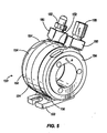
- FIG. 5 is a perspective view of the hydraulic interface 150 adapted to be positioned between the first link 136 and the second link 138 of the cylinder link assembly 130 at pivot 133.
- first end portion 154 includes a port block 180 adapted to accept a first hydraulic fitting 182.
- a hydraulic fitting 182 is adapted to be connected to a first hydraulic line (not shown) from the excavator or backhoe, which allows hydraulic oil to be provided from a hydraulic source on the excavator or backhoe to the port block 180
- second end portion 156 includes a port block 180 adapted to accept a second hydraulic fitting 186. Fitting 186 is adapted to be fitted to a second hydraulic line (not shown) that is in communication with the hydraulic source on the power machine.
- First end portion 154 has a cavity (not shown) extending from the first hydraulic fitting 182 that allows oil to move through the first end portion.
- second end portion 156 has a cavity extending from second hydraulic fitting 186 through the second end portion to allow oil to move through the second end portion.
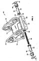
- hydraulic interface 150 is shown in an exploded view.
- Center portion 152 of hydraulic interface 150 includes a bore 208.
- a first orifice or pathway 198 and a second orifice or pathway 200 are included within the bore 208.
- the first and second orifices 19B and 200 each extend through to separate outlets (not shown) on a bottom surface of center portion 152.
- the first and second orifices 198 and 200 allow oil to pass through them when aligned with the first and second end portions 154 and 156.
- First end portion 154 includes a cylindrically-shaped shoulder 188 sized to fit within bore 208 of center portion 152.
- Shoulder 188 includes an outer seal 190 and an inner seal 192
- a bore 194 extends through the first end portion 154.
- the first end portion 154 has a cavity extending from the first hydraulic fitting 182 that allows oil to pass from hydraulic lines attached to fitting 182. The internal cavity extends within the body of first end portion 154 to an orifice (not shown) positioned between the outer seal 190 and the inner seal 192.
- first end portion 154 when first end portion 154 is positioned within the center portion 152, hydraulic oil that enters first hydraulic fitting 182 travels through the cavity within the first end portion, out the orifice, and into a volume that extends around the circumference of the shoulder 188 between the inner seal 192 and the outer seal 190. This oil is then capable of moving through the first orifice 196 and out of the hydraulic interface 150. Because the oil exits from the first end portion 154 into a volume that extends around the entire circumference of the shoulder 188, the first end portion 154 can pivot at any angle with respect to the center portion 152 without interrupting the flow of oil through the hydraulic interface 150.
- second end portion 156 has a pair of inner and outer seals (not shown) and an orifice (not shown) disposed between the inner and outer seals and in communication with internal cavity of the second end portion.
- Second end portion 156 also similarly includes a bore 195 extending through the second end portion.
- orifice 200 is positioned within or between the inner and outer seals of the second end portion 156.
- oil that enters second hydraulic fitting 186 is capable of moving through the internal cavity and exiting the hydraulic interface through orifice 200. While the hydraulic oil is described as moving into one of the first and second hydraulic fittings 182 and 186 and out of the orifices 198 and 200, it is to be understood that hydraulic oil can move in the opposite direction as well.
- Second end portion 156 includes a plurality of bores 206 that extend from an outer surface of the second end portion through the shoulder.
- the bores 206 are sized to accept fasteners 202.
- First end portion 154 has similarly positioned bores 196 such that when first and second end portions 154 and 156 are positioned within center portion 152, fasteners 202 extend through the second end portion and into the first end portion.
- Fastener couplers 204 are sized to fit within the orifices 196 of the first end portion 154.
- the fasteners 202 are engaged with the fastener couplers 204 to secure the first end portion to the second end portion.
- the fastener couplers 204 are slotted nuts.
- any other acceptable fastener coupler may be used including, without limitation, a thread cut into bore 196, a nut disposed within bore 196 or any other device.
- seals 184 are disposed between the end portions and the center portion on either side of the center portion.
- seals 184 are positioned on the outer surfaces of the first and second end portions 154 and 156.
- bores 194 and 195 are aligned together to accept a pin (not shown) that couples the hydraulic interface 150 to cylinder link assembly 130 and quick attachment mounting bracket 102.
- the bores 194 and 195 have a diameter that is larger than the pin (not shown), so the hydraulic interface 150 has some freedom of movement with respect to the pin.
- the port blocks 180 are not rigidly connected to the cylinder link assembly 130.
- the load transmitted by cylinder link assembly 130 is transmitted to the pin and the hydraulic interface 150 is a non-load bearing device.
- a mating surface 210 on cross member 112 is adapted to accept the center portion 152 of the hydraulic interface 150.
- the mating surface 210 includes a first orifice positioned to align with first orifice 198 of the center portion 152 of hydraulic interface 150, and a second orifice positioned to align with the second orifice 200 of the center portion (neither orifice is shown in FIG. 3).
- the first orifice on mating surface 210 is in communication with base orifice 178.
- oil that is ported into first hydraulic coupling 182 is capable of moving through orifice 17B and between the engaging pins 122.
- the second orifice is similarly in communication with the second hydraulic coupling 186 so that oil can be ported from the second hydraulic fitting to rod orifices located on each side of cavity 12B each of which is positioned on the rod side 164 of engaging pin 122.
- quick attachment mounting bracket 102 can have up to 270 degrees of rotational travel with respect to the cylinder link assembly 130. Because the interfaces between the first and second end portions 154 and 156 and the center portion 152 are accomplished as described above, the quick attachment mounting bracket 102 can move without requiring hydraulic hoses to travel the up to 270 degrees of rotation.
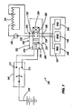
- FIG. 7 is a simplified schematic 220 that illustrates the flow of hydraulic oil associated with extending and retracting the engaging pins 122 of quick attachment mounting bracket 102.
- Schematic 220 illustrates housing 124 which is hydraulically connected to a valve 222, which, in one embodiment, is located on the excavator or backhoe.
- Valve 222 has a pair of interfaces 232 and 234 on a first side 230 and a pair interfaces 238 and 240 on a second side 236.
- Interface 238 provides a connection between the valve 222 and first hydraulic fitting 182 and eventually to base orifice 178.
- Interface 240 is connected to second hydraulic fitting 186 and eventually to the pair of rod orifices 244.
- the rod orifices are designated as rod orifices 244 on FIG. 7 and are described above, but are otherwise not shown in any of the figures.
- Interface 232 on a first side 230 of valve 222 is coupled with the output aide of pump 226. Interface 232 then, has pressurized oil available. Interface 234 is in communication with tank 224. Thus, interface at 234 is under no or minimal hydraulic pressure.
- the operator input 242 is a switch having two output poles 272 and 274.
- Input switch 242 is a three-position switch having a neutral or unactuated position wherein power from battery 276 is applied to neither output pole 272 nor output pole 274.
- input switch 242 has a first actuated position that provides battery power to output pole 272 and a second actuated position that provides battery power to output pole 274.
- Valve 222 includes three positions, a neutral position 252, a first energized position 254, and a second energized position 256.
- Valve 222 in one embodiment, is actuated by one or more electronic actuators 270, which are coupled to the output poles 272 and 274 of the operator input 242.
- the electronic actuators 270 in one embodiment, are solenoids, which respond to a signal from output pole 272 by causing valve 222 to move to the first energized position 254 and to a signal from output pole 274 to cause valve 222 to move to the second energized position 256. If there is no signal present from either pole 272 or 274, electronic actuator causes or allows value 222 to move to a neutral position 252.
- electronic actuator 270 can include a pair of solenoids and the actuation of one or the other can cause the valve 222 to move into different positions .
- any other type of actuator can be used, including, as an example, a linear actuator coupled to a valve spool to shift the spool into different positions.
- individual solenoid valves can be used to independently control the flow of oil from two interfaces 232 and 234 on the first side 230 of the valve 222 to the two interfaces 238 and 240 on the second side 236 of the valve.
- actuator 270 can act indirectly on valve 222 by, for example, porting oil to shift a valve spool within valve 222.
- operator input 242 is described above as a switch directly coupled to electronic actuator, the operator input can take a number of different forms, including a switch coupled to an electronic controller that, in turn, supplies signals to the valve 222.
- valve 222 When the valve 222 is in the neutral position 252, interfaces 238 and 240 are blocked so that no oil can travel in or out of the base orifice 178 or the rod orifices 244. Thus, the pins 122 remain in their current position, whether retracted or extended.
- valve 222 can have hydraulic components such as check valves or pilot operated check valves.
- Schematic 230 is a simplified schematic to show the functional results that occur when the valve 222 is in a particular position. Any number of implementations of valve 222 can be incorporated without departing from the scope of the embodiments described herein.
- the interface 238 When the valve 222 is in the first energized position 254, the interface 238 is in communication with tank 224 to allow oil from the base orifice 178 to flow to tank. Further, interface 240 is in communication with interface 232, which supplies pressurized hydraulic oil to rod orifices 244. Thus, in the first energized position 254, the oil ported into the rod orifices 244, urge the engaging pins 122 to be retracted.
- the interface 238 When the valve 222 is in the second energized position 256, the interface 238 is in communication with interface 232, which supplies pressurized hydraulic oil to the base orifice 178. Further, the interface 240 is in communication with tank 224 to allow oil from the rod orifices 244 to flow to the tank. Thus, in the second energized position 256, the oil ported into the base orifice 178 urge the engaging pins 122 to be extended.
- the disclosed embodiments provides a number of advantages By providing an arrangement of the type described above, an improved method of mounting attachments to equipment has been provided, Further, the addition of a hydraulic interface that allows oil to be ported through it even as the attachment is pivoting throughout its entire range of motion, the need for hydraulic supply lines that can withstand repeated cycles of rotation has been eliminated. Int addition, the incorporation of retaining pins into' the extended engagement members provides additional retention of any attachment that has been connected to the quick attachment mounting bracket.
Landscapes
- Engineering & Computer Science (AREA)
- Mechanical Engineering (AREA)
- Mining & Mineral Resources (AREA)
- Civil Engineering (AREA)
- General Engineering & Computer Science (AREA)
- Structural Engineering (AREA)
- Operation Control Of Excavators (AREA)
- Fluid-Pressure Circuits (AREA)
Abstract
Description
- The disclosed embodiments relate to interchangeable tool attachments such as buckets, grapples, hydraulic hammers, tampers, augers and the like used with a power operated arm of an implement such as an excavator or backhoe. More particularly, the embodiments relate to an attachment device that allows attachments to be quickly attached to the power operated arm.
- FIG. 1A illustrates a prior art
attachment mounting bracket 22 pivotally attached to an end portion of an excavator arm 18 (shown in fragmentary view) at boomarm pivot joint 20.Excavator arm 18 is attached to an excavator or backhoe represented byblock 10.Quick attachment mount 22 is also pivotally attached tohydraulic cylinder 14 through acylinder link 26.Hydraulic cylinder 14 is attached to a portion of the excavator or backhoe and is in communication with hydraulic controls represented byblock 12 located on the excavator or backhoe. Across link 32 is pivotally attached to both the end ofcylinder rod 16, which extends fromhydraulic cylinder body 14 and excavator arm 19. Thecross link 32 is attached to theexcavator arm 18 at crosslink pivot joint 36. Apin 34 extends through both thecross link 32 and theexcavator arm 18 to provide a pivotal attachment. Likewise, apin 30 at cylinderlink pivot joint 28 pivotally attaches thecylinder rod 16 with both thecross link 32 and thecylinder link 26.Cylinder link 26 is pivotally attached to thequick attachment mount 22 atpivot 25, with apin 27 extending through both thecylinder link 26 and thequick attachment mount 22. - A fragmentary portion of an
attachment 40 is partially engaged with thequick attachment mount 22 atpin 38.Attachment 40 includes anengagement region 44 which is adapted to engage withsupport region 46 ofquick attachment mount 22 when the quick attachment mount is rotated aboutpin 38 in the direction ofarrow 48. Theattachment 40 is then secured to thequick attachment mount 22 atsupport region 46. - When the
attachment 40 is fixedly attached to theattachment mount 22, actuation of thehydraulic cylinder 14 to extend or retract thecylinder rod 16 will cause theattachment 40 to pivot about boomarm pivot joint 20. Attachments of the type used with excavators or back hoes can have a pivotal rotation of approximately 270 degrees. - FIG. 1B illustrates in more detail the prior art
quick attachment mount 22.Quick attachment mount 22 includes afirst side plate 50 and asecond side plate 52.First side 50 andsecond side 52 each have a pair ofapertures quick attachment mount 22 is positioned with respect to excavator arm is theaperture 21 in FIG. 1B aligns with the boom arm to create the boomarm pivot joint 20. Similarly, theaperture 23 in FIG. 1B is aligned to engagecylinder link 26 to createpivot 25. -
Side plates cradle 42.Retainer 42 and first andsecond sides pin 38.Pin 38 is positioned to extend outside the width ofretainer 42 to provide an engagement surface for an attachment.First aide 50 andsecond aide 52 are also connected via asupport region 46, a multi-surfaced crossmember that extends along an end of the each of the first and second sides - As shown in FIG. 1A,
attachment 40 engagespin 38 and is capable of rotating onpin 38 in either direction. When thequick attachment mount 22 is rotated in position such thatengagement region 44 is in connection with or is positionedadjacent support region 46, a portion of theattachment 40 is positioned adjacent to retainer orcradle 42. Thus thecradle 42 serves to assist in holding the attachment in place with respect to thequick attachment mount 22. -
Support region 46 is positioned to engage and support theengagement region 44 ofattachment 40 when thequick attachment mount 22 is rotated into position. In addition, theengagement region 44 has a pair of bores (not shown) that match up with a pair ofbores 54 that extend through theengagement surface 46. Thus, when theattachment 40 is rotated into position, the attachment can be fixedly secured to thequick attachment mount 22. Typically, a fastener arrangement such as a nut and bolt or a pin of some sort is extended through the aligned bores to fixedly attach the attachment to theattachment mount 22. - However, requiring the use of fasteners such as nuts and bolts to secure the attachment to the attachment mount is time consuming. Often times, an operator wants to quickly disengage one attachment and engage a second attachment to do different types of work at a work site. Thus, what is needed is an attachment mount that provides a quicker and easier method of attaching the attachment to the attachment mount.
- One embodiment is directed toward an hydraulic interface between a power machine having an hydraulic power system and an attachment mounting bracket having an hydraulically actuated engagement member. The hydraulic interface includes a first portion capable of being coupled to the hydraulic power system and a second portion fixedly attached to the attachment mounting bracket. The first portion is pivotally coupled to the second portion so that the attachment bracket is capable of pivoting with respect to the first portion of the hydraulic interface. The second portion includes an outlet capable of providing oil from the outlet of the first portion to the attachment mounting bracket. The hydraulic interface can include a third portion that is also pivotally coupled to the second portion and is fixedly attached to the first portion. The third portion can include an inlet capable of being coupled to the hydraulic power system and an outlet. The second portion can further include an outlet capable of providing oil from the outlet of the third portion to the attachment mounting bracket. The attachment mounting bracket is pivotable with respect to the power machine and the hydraulically actuated engagement member can be actuated to secure or release an attachment with respect to the attachment mounting bracket.
- One embodiment is directed toward an attachment interface system configured to couple an attachment to a power machine. The power machine haa an hydraulic power system and at least one arm with an attachment mounting bracket pivotally attached to the at least one arm. The attachment bracket includes a housing with an engagement member located therein capable of moving from a first position to a second position to engage and secure the attachment to the mounting bracket. The system further includes an hydraulic interface member fixedly attached to the mounting bracket and capable of providing hydraulic oil to the housing to move the engagement member from a first to a second position. At least a portion of the hydraulic interface member is capable of pivoting with respect to the mounting bracket.
- One embodiment is directed toward a method of providing an attachment interface between a power machine and an attachment. The method includes pivotally attaching a mounting bracket to the power machine having at least one attachment engagement member, capable of moving between a first position and a second position under hydraulic power. A hydraulic interface is provided between the power machine and the mounting bracket. The hydraulic interface is fixedly attached to the mounting bracket and includes an internal path for receiving hydraulic oil from the hydraulic power source and providing oil to the mounting bracket to manipulate the attachment engagement member. The hydraulic interface includes a first portion, which is pivotable with respect to a second portion, which is fixedly attached to the mounting bracket. The hydraulic interface is connected to the hydraulic power source and oil is provided in response to an operator input to the mounting bracket to move the engagement member between the first and second position.
- The concepts presented herein will be further explained with reference to the attached figures, wherein like structure or system elements can be referred to by like reference numerals throughout the several views.
- FIG. 1A is schematic side elevational view of a typical excavator arm end portion having an attachment mounting bracket according to the prior art.
- FIG. 1B is a perspective schematic view of the attachment mounting bracket shown in FIG. 1A.
- FIG. 2 is a perspective view of a hydraulic quick attachment mounting bracket having hydraulically actuated attachment engagement members and coupled to both a link capable of being attached to an actuator and a pivotable hydraulic interface according to one embodiment.
- FIG. 3 is an exploded view of a portion of the hydraulic quick attachment mount of FIG. 2, illustrating the components located within a housing, including the hydraulically actuated attachment retaining members.
- FIG. 4A is a cross-sectional view of the housing taken along line 4-4 in FIG. 2 according to one embodiment, illustrating the engagement members in a retracted position.
- FIG. 4B is a cross-sectional view of the housing taken along line 4-4 in FIG. 2, illustrating the engagement members in an extended position.
- FIG. 4C is a detailed view of a portion of the cross-section of FIG. 4A, illustrating an orifice capable of permitting hydraulic oil to flow into and out of the housing.
- FIG. 5 is a perspective view of the pivotable hydraulic assembly of FIG. 2, illustrating hydraulic fittings attached to the assembly according to one embodiment.
- FIG. 6 is an exploded view of the pivotable hydraulic assembly of FIG. 5.
- FIG. 7 is a schematic diagram illustrating a system for providing hydraulic oil to control the engagement members.
- While the above-identified figures set forth one or more embodiments, other embodiments are also contemplated, as noted herein. In all cases, concepts presented herein describe the embodiments by way of representation and not by limitation. It should be understood that numerous other modifications and embodiments can be devised by those skilled in the art which fall within the scope and spirit of the principles of these embodiments.
- FIG. 2 illustrates a
quick attachment assembly 100 having hydraulically actuated extendable engagement members or pins 122. the assembly being of the type adapted to be connected to the end of an arm such asexcavator arm 18 according to one embodiment.Quick attachment assembly 100 includes quickattachment mounting bracket 102 andcylinder link assembly 130, which is pivotally attached to the quick attachment mounting bracket at pivot joint 133. In addition, anhydraulic interface 150 is coupled to the quick attachment assembly atpivot 133.Hydraulic interface 150, which will be discussed in more detail below, is configured to be attached to an hydraulic power supply (not shown). In addition,hydraulic interface 150 is fixedly coupled to quickattachment mounting bracket 102 to provide hydraulic control engagement pins 122. - Quick
attachment mounting bracket 102 includes afirst side 108 and asecond side 110 coupled together on either side of across member 112. The first andsecond sides proximal end 104 of the quick attachment mounting bracket to adistal end 106. At thedistal end 106 of the quickattachment mounting bracket 102, the first andsecond sides proximal end 104 of the quick attachment mounting bracket. The curved shape of the first andsecond sides cross member 112, which follows the shape of the first and second sides, provide an attachment cradle or retainer 118 capable of supporting a portion of an attachment such as theattachment 40 shown in a fragmentary view in FIG. 1A. Apin 120 extends from thesecond side 110 in the region of the attachment cradle 118. A second pin (not shown) similarly extends from thefirst side 108 of the quickattachment mounting bracket 112 in a similar position. - The
pins 120 are configured to accept and support a portion of the attachment similar to pin 3B shown in FIGS. 1A and 1B. In addition, thequick attachment assembly 100 includes the engagement members or pins 122 (one of which is shown in a retracted position on second side 110) capable of extending from each of the first andsecond sides attachment mounting bracket 102 near theproximal end 104 of the quick attachment mounting bracket. The quickattachment mounting bracket 102 includes ahousing 124 located between the first andsecond sides -
Cylinder link assembly 130 is shown coupled to the quickattachment mounting bracket 102 at pivot joint 133.Cylinder link assembly 130 has afirst link 136 andsecond link 138 each coupled to across member 140 that extends between a portion of the first and second links. Each of the first andsecond links bore 142 formed into aproximal end 132 and adistal end 134 of thecylinder link assembly 130. Thebores 142 are positioned to accept a pin (not shown) extending through the bore to attach the cylinder link to the quickattachment mounting bracket 102 on theproximal end 132 and a cylinder or other links or brackets (not shown) on thedistal end 134 of the cylinder link. Abushing 144 is inserted into each of thebores 142 to provide an engagement surface for the pins where they are inserted into the bores. - Returning again to the pivot joint 133, a pin (not shown) extends through the first and
second sides attachment mounting bracket 102 and the first andsecond links cylinder link assembly 130 to pivotally connect the cylinder link assembly to the quickattachment mounting bracket 102. In addition, ahydraulic interface 150 is positioned between the first andsecond links cylinder link assembly 130. Thehydraulic interface 150 is adapted to accept a pin (not shown) through its center portion to secure the hydraulic interface between the first andsecond links hydraulic interface 150 includes acenter portion 152, which, in one embodiment, is surrounded by afirst end portion 154 andsecond end portion 156. Thecenter portion 152 of the hydraulic interface is fixedly attached to the quickattachment mounting bracket 102. As is shown in FIG. 2, thecenter portion 152 of thehydraulic interface 150 includes abracket 158 positioned to extend along a portion of thecross member 112 of the quickattachment mounting bracket 102. Thebracket 158 is attached to thecross member 112 with two fasteners 160 (only one shown), although any suitable fastening structure may be used, such as, for example, a weld, a clip, or a clamp. - As has been discussed above,
cylinder link assembly 130 is pivotally connected to quickattachment mounting bracket 102 to allow the quick attachment mounting bracket to pivot with respect to the cylinder link assembly as the cylinder rod (not shown), which is attached to the cylinder link assembly, extends or retracts. Because thecenter portion 152 of thehydraulic interface 150 is fixedly attached to thecross member 112, the center portion will pivot with the quickattachment mounting bracket 102. As will be discussed below, thefirst end portion 154 and thesecond end portion 156 are not fixedly attached to thehydraulic interface 150. Thus, thefirst end portion 154 and thesecond end portion 156 do pivot with respect to thecenter portion 152 of thehydraulic interface 150 when the quickattachment mounting bracket 102 pivots with respect tocylinder link assembly 130. - FIG. 3 illustrates an exploded view of the quick
attachment mounting bracket 102 ofassembly 100 with an exploded view of the components located within thehousing 124.Housing 124 includes acavity 128 that extends therethrough the first side 10B to thesecond side 110.Housing 124 houses a pair of the engagingpins 122, which are capable of extending out of cavity 12B on each of the first andsecond sides attachment mounting bracket 102. In one embodiment, thepins 122 are hydraulically actuated to extend and retract in response to an operator input. Hydraulic oil ported into and out of thehousing 124 will cause the pins to extend or retract, the details of which will be discussed below. Engagingpins 122, when retracted, are positioned within thecavity 128. - Engaging
pins 122 include abase 162 and arod 164 attached to and extending from the base. Aninternal bore 166 is formed through thebase 162 and into therod 164. Across bore 168 is formed through therod 164 of engagingpin 122 near an end opposing thebase 162. Aspring 146 is positioned within thecavity 128 and is sized and positioned to extend into theinternal bore 166 of each of the engaging pins 122.Spring 146 will be discussed in detail below.Bushing 148 is adapted to fit snugly over therod 164 ofpin 122 and within thecavity 128. A retainingpin 170, which in one embodiment is a lynch pin, is adapted to fit into the cross bore 16B of each of the engagingpins 122 when thepins 122 are extended. - FIGS. 4A and 4B illustrate a crose sectional view of the
housing 124 of quickattachment mounting bracket 102 taken along line 4 as shown in FIG. 2. In addition, a portion of anattachment 114 positioned adjacent the quickattachment mounting bracket 102 is shown. FIG. 4A shows the engagingpins 122 in retracted position. FIG. 4B shows the engagingpins 122 in an extended position. When the pins are in a retracted position, thebase 162 of each of the engagingpine 122 is abutted against a reduceddiameter portion 176 ofcavity 128. Thebase 162 of thepins 122 include agroove 172 that extends circumferentially about the base of the pin. A seal (not shown) such as an O-ring can be disposed within thegroove 172 to prevent hydraulic oil from moving within thecavity 128 from one side of thegroove 172 to the other aide. Spring 146 (not shown in FIGS. 4A and 4B) is positioned within theinternal bores 166. When it is desired to extend the engagingpins 122, hydraulic oil is ported into thecavity 128 through abase orifice 178, which is shown in greater detail in FIG. 4C. As the pressurized hydraulic oil enters the reduceddiameter portion 176 of thecavity 128, the hydraulic oil pushes against the internal bores. 166 and the base 162 to cause therods 164 to extend out of the cavity 12B. - When the engaging
pine 122 are positioned in a retracted state as shown in FIG. 4A, pressurized hydraulic oil (not shown) is positioned on therod side 164 of the engagingpine 122. The hydraulic oil is ported into thecavity 128 through a pair of rod orifices (not shown), the rod orifices located such that one is on each side of the cavity, to overcome thespring 146 which is disposed within thecavities 166 of the engaging pins 122.Bushings 148 are held in position within thecavity 128 by a ring orclip 174 circumferentially located on an outer portion of the bushing. Each of thebushings 148 have one ormore seals 149 such as o-rings on itsoutside diameter 147 to prevent hydraulic oil from leaking out of thecavity 128. Further, each of thebushings 146 haveseals 145 such as o-rings between itsinside diameter 143 androd 164 of the engagingpins 122, thereby sealing the end of the cavity, while allowing the engagingpins 122 to extend through out of thehousing 124 when it is desirable. - When the oil is ported into the reduced
diameter portion 176 throughorifice 178, thepins 122 are urged apart to extend out of thecavity 128 of thehousing 124. As the pins extend, any hydraulic oil located on therod side 164 of the engagingpins 122 is ported out of thecavity 124 through the rod orifices (not shown) on each side of thecavity 124. The hydraulic oil located within thecavity 124 between thebase portions 162 of the pine will hold the pins extended. In addition,spring 146 applies a force against each of the engagingpins 122 to hold the pine in an extended position even if there is a loss of hydraulic pressure between thebases 162 of the pins within thecavity 128. - As shown in FIG. 4B, the engaging
pins 122 extend out of thecavity 128 of thehousing 124 and through bores located on each side of that portion of theattachment 114 positioned outside of thehousing 124. After the engagingpins 122 have been fully extended, retainingpin 170 is inserted into thecross bore 168 on each of thepins 122 to provide additional retention for holding theattachment 114 onto the engaging pins 122. - As described above, hydraulic oil is used to extend the
pins 122. To retract thepins 122, retainingpins 170 must be removed. Once the retaining pins 170 are removed, hydraulic oil is ported through the rod orifices (not shown) and into thecavity 128 on therod 164 side of the engagingpins 122 to urge the engaging pins back toward the reduceddiameter portion 176. At this time, the hydraulic oil located in the cavity between thepins 122 is urged out of thebase orifice 178. A detailed description of how oil is ported into and out of thecavity 128 of thehousing 124 will be discussed below. - FIG. 5 is a perspective view of the
hydraulic interface 150 adapted to be positioned between thefirst link 136 and thesecond link 138 of thecylinder link assembly 130 atpivot 133. As shown in FIG. 5,first end portion 154 includes aport block 180 adapted to accept a firsthydraulic fitting 182. Ahydraulic fitting 182 is adapted to be connected to a first hydraulic line (not shown) from the excavator or backhoe, which allows hydraulic oil to be provided from a hydraulic source on the excavator or backhoe to theport block 180 Likewise,second end portion 156 includes aport block 180 adapted to accept a secondhydraulic fitting 186. Fitting 186 is adapted to be fitted to a second hydraulic line (not shown) that is in communication with the hydraulic source on the power machine.First end portion 154 has a cavity (not shown) extending from the firsthydraulic fitting 182 that allows oil to move through the first end portion. Likewise,second end portion 156 has a cavity extending from secondhydraulic fitting 186 through the second end portion to allow oil to move through the second end portion. - Referring to FIG. 6,
hydraulic interface 150 is shown in an exploded view.Center portion 152 ofhydraulic interface 150 includes abore 208. Within thebore 208 are included a first orifice orpathway 198 and a second orifice orpathway 200. The first andsecond orifices 19B and 200 each extend through to separate outlets (not shown) on a bottom surface ofcenter portion 152. The first andsecond orifices second end portions -
First end portion 154 includes a cylindrically-shapedshoulder 188 sized to fit withinbore 208 ofcenter portion 152.Shoulder 188 includes anouter seal 190 and an inner seal 192 A bore 194 extends through thefirst end portion 154. Whenfirst end portion 154 is positioned withincenter portion 152 theorifice 198 is located between theinner seal 192 and theouter seal 190. Thefirst end portion 154, as described above, has a cavity extending from the firsthydraulic fitting 182 that allows oil to pass from hydraulic lines attached to fitting 182. The internal cavity extends within the body offirst end portion 154 to an orifice (not shown) positioned between theouter seal 190 and theinner seal 192. Thus, whenfirst end portion 154 is positioned within thecenter portion 152, hydraulic oil that enters firsthydraulic fitting 182 travels through the cavity within the first end portion, out the orifice, and into a volume that extends around the circumference of theshoulder 188 between theinner seal 192 and theouter seal 190. This oil is then capable of moving through thefirst orifice 196 and out of thehydraulic interface 150. Because the oil exits from thefirst end portion 154 into a volume that extends around the entire circumference of theshoulder 188, thefirst end portion 154 can pivot at any angle with respect to thecenter portion 152 without interrupting the flow of oil through thehydraulic interface 150. - Similarly,
second end portion 156 has a pair of inner and outer seals (not shown) and an orifice (not shown) disposed between the inner and outer seals and in communication with internal cavity of the second end portion.Second end portion 156 also similarly includes abore 195 extending through the second end portion. When thesecond end portion 156 is positioned within thecenter portion 152 of thehydraulic interface 150,orifice 200 is positioned within or between the inner and outer seals of thesecond end portion 156. Thus, oil that enters secondhydraulic fitting 186 is capable of moving through the internal cavity and exiting the hydraulic interface throughorifice 200. While the hydraulic oil is described as moving into one of the first and secondhydraulic fittings orifices -
Second end portion 156 includes a plurality ofbores 206 that extend from an outer surface of the second end portion through the shoulder. Thebores 206 are sized to acceptfasteners 202.First end portion 154 has similarly positioned bores 196 such that when first andsecond end portions center portion 152,fasteners 202 extend through the second end portion and into the first end portion.Fastener couplers 204 are sized to fit within theorifices 196 of thefirst end portion 154. Thefasteners 202 are engaged with thefastener couplers 204 to secure the first end portion to the second end portion. In one embodiment as shown in FIG. 6, thefastener couplers 204 are slotted nuts. Any other acceptable fastener coupler may be used including, without limitation, a thread cut intobore 196, a nut disposed withinbore 196 or any other device. When the first and second end portions are positioned withincenter portion 152,seals 184 are disposed between the end portions and the center portion on either side of the center portion. Similarly seals 184 are positioned on the outer surfaces of the first andsecond end portions hydraulic interface 150 tocylinder link assembly 130 and quickattachment mounting bracket 102. Thebores hydraulic interface 150 has some freedom of movement with respect to the pin. Further the port blocks 180 are not rigidly connected to thecylinder link assembly 130. Thus, the load transmitted bycylinder link assembly 130 is transmitted to the pin and thehydraulic interface 150 is a non-load bearing device. - Returning briefly to FIG. 3, a
mating surface 210 oncross member 112 is adapted to accept thecenter portion 152 of thehydraulic interface 150. Themating surface 210 includes a first orifice positioned to align withfirst orifice 198 of thecenter portion 152 ofhydraulic interface 150, and a second orifice positioned to align with thesecond orifice 200 of the center portion (neither orifice is shown in FIG. 3). The first orifice onmating surface 210 is in communication withbase orifice 178. Thus, oil that is ported into firsthydraulic coupling 182 is capable of moving through orifice 17B and between the engaging pins 122. The second orifice is similarly in communication with the secondhydraulic coupling 186 so that oil can be ported from the second hydraulic fitting to rod orifices located on each side of cavity 12B each of which is positioned on therod side 164 of engagingpin 122. - When the
hydraulic interface 150 is assembled, as described above,center portion 152 is fixedly attached to thecross member 112 of quickattachment mounting bracket 102. Thus thecenter portion 152 rotates with the quickattachment mounting bracket 102 when it rotates with respect to thecylinder link assembly 130. However,first end portion 154 andsecond end portion 156 are not attached to thecross member 112, and do not rotate with the quickattachment mounting bracket 102. In other words, thefirst end portion 154 and thesecond end portion 156 remain aligned with thecylinder link assembly 130 and not with the quickattachment mounting bracket 102. In one embodiment, quickattachment mounting bracket 102 can have up to 270 degrees of rotational travel with respect to thecylinder link assembly 130. Because the interfaces between the first andsecond end portions center portion 152 are accomplished as described above, the quickattachment mounting bracket 102 can move without requiring hydraulic hoses to travel the up to 270 degrees of rotation. - FIG. 7 is a simplified schematic 220 that illustrates the flow of hydraulic oil associated with extending and retracting the engaging
pins 122 of quickattachment mounting bracket 102.Schematic 220 illustrateshousing 124 which is hydraulically connected to avalve 222, which, in one embodiment, is located on the excavator or backhoe.Valve 222 has a pair ofinterfaces first side 230 and a pair interfaces 238 and 240 on asecond side 236.Interface 238 provides a connection between thevalve 222 and firsthydraulic fitting 182 and eventually tobase orifice 178.Interface 240 is connected to secondhydraulic fitting 186 and eventually to the pair ofrod orifices 244. The rod orifices are designated asrod orifices 244 on FIG. 7 and are described above, but are otherwise not shown in any of the figures.Interface 232 on afirst side 230 ofvalve 222 is coupled with the output aide ofpump 226.Interface 232 then, has pressurized oil available.Interface 234 is in communication withtank 224. Thus, interface at 234 is under no or minimal hydraulic pressure. - In one embodiment, the
operator input 242 is a switch having twooutput poles Input switch 242 is a three-position switch having a neutral or unactuated position wherein power frombattery 276 is applied to neitheroutput pole 272 noroutput pole 274. In addition,input switch 242 has a first actuated position that provides battery power tooutput pole 272 and a second actuated position that provides battery power tooutput pole 274. -
Valve 222 includes three positions, aneutral position 252, a firstenergized position 254, and a secondenergized position 256.Valve 222, in one embodiment, is actuated by one or moreelectronic actuators 270, which are coupled to theoutput poles operator input 242. Theelectronic actuators 270, in one embodiment, are solenoids, which respond to a signal fromoutput pole 272 by causingvalve 222 to move to the firstenergized position 254 and to a signal fromoutput pole 274 to causevalve 222 to move to the secondenergized position 256. If there is no signal present from eitherpole value 222 to move to aneutral position 252. - It is to be understood that the interface between the
operator input 242 and thevalve 222 can have many different implementations without departing from the scope of the embodiments disclosed herein. For example,electronic actuator 270 can include a pair of solenoids and the actuation of one or the other can cause thevalve 222 to move into different positions . In addition, any other type of actuator can be used, including, as an example, a linear actuator coupled to a valve spool to shift the spool into different positions. As another example, individual solenoid valves can be used to independently control the flow of oil from twointerfaces first side 230 of thevalve 222 to the twointerfaces second side 236 of the valve. Further,actuator 270 can act indirectly onvalve 222 by, for example, porting oil to shift a valve spool withinvalve 222. In addition, althoughoperator input 242 is described above as a switch directly coupled to electronic actuator, the operator input can take a number of different forms, including a switch coupled to an electronic controller that, in turn, supplies signals to thevalve 222. - When the
valve 222 is in theneutral position 252,interfaces base orifice 178 or therod orifices 244. Thus, thepins 122 remain in their current position, whether retracted or extended. It should be understood thatvalve 222 can have hydraulic components such as check valves or pilot operated check valves.Schematic 230 is a simplified schematic to show the functional results that occur when thevalve 222 is in a particular position. Any number of implementations ofvalve 222 can be incorporated without departing from the scope of the embodiments described herein. - When the
valve 222 is in the firstenergized position 254, theinterface 238 is in communication withtank 224 to allow oil from thebase orifice 178 to flow to tank. Further,interface 240 is in communication withinterface 232, which supplies pressurized hydraulic oil torod orifices 244. Thus, in the firstenergized position 254, the oil ported into therod orifices 244, urge the engagingpins 122 to be retracted. - When the
valve 222 is in the secondenergized position 256, theinterface 238 is in communication withinterface 232, which supplies pressurized hydraulic oil to thebase orifice 178. Further, theinterface 240 is in communication withtank 224 to allow oil from therod orifices 244 to flow to the tank. Thus, in the secondenergized position 256, the oil ported into thebase orifice 178 urge the engagingpins 122 to be extended. - The disclosed embodiments provides a number of advantages By providing an arrangement of the type described above, an improved method of mounting attachments to equipment has been provided, Further, the addition of a hydraulic interface that allows oil to be ported through it even as the attachment is pivoting throughout its entire range of motion, the need for hydraulic supply lines that can withstand repeated cycles of rotation has been eliminated. Int addition, the incorporation of retaining pins into' the extended engagement members provides additional retention of any attachment that has been connected to the quick attachment mounting bracket.
- Although several alternative embodiments have been described herein, workers skilled in the art will recognize that changes may be made in form and detail without departing from the spirit and the scope of the embodiments.
Claims (22)
- A hydraulic interface between a power machine having an hydraulic power system and an attachment mounting bracket having an hydraulically actuated engagement member, comprising:a first portion having a path for accepting hydraulic oil including an inlet capable of being coupled to the hydraulic power system and an outlet; anda second portion fixedly attached to the attachment mounting bracket, wherein the first portion is pivotally coupled to the second portion and the second portion includes a first pathway capable of providing oil from the outlet of the first portion to the attachment mounting bracket.
- The interface of claim 1, wherein the second portion is fixedly coupled to the attachment mounting bracket so that the first pathway of the second portion is in communication with a first orifice that extends into the attachment mounting bracket to allow hydraulic oil to move from the hydraulic interface to the mounting bracket.
- The interface of claim 1, wherein the first portion includes a cylindrically-shaped member that includes the outlet of the first portion, wherein the second portion includes a bore having a surface and is configured to accept the cylindrically-shaped member therein, and wherein the outlet of the first portion is positioned within the bore of second portion when the first portion is pivotally coupled to the second portion.
- The interface of claim 3, wherein the cylindrically-shaped member of the first portion includes a first seal and a second seal extending about the circumference of the cylindrically-shaped member, wherein the first and second seals engage the surface of the bore of the second portion to define a volume between the first and second seals, and wherein the outlet of the first portion is positioned between the first and second seals.
- The interface of claim 4, wherein the first pathway of the second portion is in communication with the volume between the first and second seals.
- The interface of claim 1, further comprising a third portion fixedly attached to the first portion and pivotally coupled to the second portion, wherein the third portion includes a path for accepting hydraulic oil including an inlet capable of being coupled to the hydraulic power system and an outlet and wherein the second portion includes a second pathway capable of providing oil from the outlet of the third portion to the attachment mounting bracket.
- The interface of claim 1, wherein the attachment mounting bracket is pivotally coupled to the power machine and wherein a hydraulically actuated engagement member is capable of being actuated to secure or release an attachment with respect to the power machine.
- An attachment interface system configured to couple an attachment to a power machine having a hydraulic power system and at least one arm, the system comprising:an attachment mounting bracket pivotally attached to the at least one arm and capable of pivoting about the arm under power, the attachment mounting bracket including:a first engagement member for engaging and securing the attachment, the first engagement member having an extendable portion configured to move between a first position and a second position under hydraulic power, wherein the extendable portion of the first engagement member is capable of engaging the attachment in the second position to fixedly couple the attachment to the power machine;a housing having a cavity therein configured to accept the first engagement member, wherein the housing has a first orifice extending from an exterior surface of the housing into the cavity; anda hydraulic interface member fixedly attached to the attachment mounting bracket and having a first internal path extending therethrough capable of accepting hydraulic fluid, the first internal path having an inlet configured to be capable of communication with the hydraulic power system and an outlet positioned to be in communication with the first orifice located on the exterior surface of the housing, wherein a portion of the hydraulic interface member configured to be capable of communication with the hydraulic power system is capable of rotating with respect to a portion of the hydraulic interface member having the outlet.
- The system of claim 8 further comprising a spring positioned within the housing to retain the first engagement member in the second position if the system experiences a loss of hydraulic power when the first engagement member is in the second position.
- The system of claim 8, wherein the power machine further includes a hydraulic cylinder and a link having first and second ends, wherein the link is attached to the hydraulic cylinder at the first end and attached to both the attachment mounting bracket and the hydraulic interface at a pivotable coupling at the second end.
- The system of claim 10, wherein the link transfers a load to the pivotable coupling and hydraulic interface is free from bearing the load.
- The system of claim 8, wherein the housing includes a second orifice extending from the exterior surface of the housing into the cavity, and wherein the hydraulic interface member further includes a second internal path, extending from an inlet configured to be capable of communication with the hydraulic power system to an outlet positioned to be in communication with the second orifice.
- The system of claim 8, wherein the attachment mounting bracket further comprises a second engagement member configured to move between a first position and a second position under hydraulic power for engaging and securing the attachment when in the second position.
- The system of claim 13, wherein the cavity within the housing is configured to accept the second engagement member.
- The system of claim 8, wherein the hydraulic power system is configured to provide hydraulic oil to the inlet of the first internal path of the hydraulic member in response to, a remote signal and wherein an amount of the hydraulic oil is capable of being introduced into the cavity of the housing.
- The system of claim 15, wherein the first engagement member is configured to move from the first position to the second position in response to the introduction of the amount of hydraulic oil into the cavity.
- The system of claim 13, wherein the hydraulic power system is configured to provide hydraulic oil to the inlet of the second internal path of the hydraulic interface member in response to a remote signal, and wherein an amount of the hydraulic oil is capable of being introduced into the cavity of the housing.
- The system of claim 17, wherein the first engagement member is configured to move from the second position to the first position in response to the introduction of the amount of hydraulic oil into the cavity.
- A method of providing an attachment interface between an attachment and a power machine having an arm and a hydraulic power source, comprising:pivotally attaching a mounting bracket configured to accept the attachment to the arm, the mounting bracket having at least one attachment engagement member, capable of moving between a first position and a second position under hydraulic power;providing a hydraulic interface having, an internal path for receiving hydraulic oil, the hydraulic interface including a first portion that is rotatable with respect to a second portion that is fixedly attached to the mounting bracket, wherein the internal path has an inlet for receiving hydraulic oil and the second portion has an outlet to provide oil to the mounting bracket and wherein the internal path extends through a pivot between the first portion and the second portion;connecting the hydraulic interface to the hydraulic power source; andproviding hydraulic oil from the hydraulic power source to move the at least one attachment engagement member between a first position and a second position in response to an operator input.
- The method of claim 19, further comprising the step of positioning the attachment adjacent the mounting bracket, wherein the step of providing hydraulic oil from the hydraulic power source includes providing oil to move the at least one engagement member from the first position to the second position to secure the attachment to the mounting bracket.
- The method of claim 19, further comprising the step of attaching a retaining pin to the at least one attachment engagement member.
- The method of claim 19, further comprising the step of providing hydraulic oil from the hydraulic power source to move the at least one attachment engagement member from the second position to the first position to release the attachment from the mounting bracket.
Applications Claiming Priority (1)
| Application Number | Priority Date | Filing Date | Title |
|---|---|---|---|
| US11/411,162 US7690880B2 (en) | 2006-04-25 | 2006-04-25 | Locking device for hydraulic attachment interface |
Publications (3)
| Publication Number | Publication Date |
|---|---|
| EP1849921A2 true EP1849921A2 (en) | 2007-10-31 |
| EP1849921A3 EP1849921A3 (en) | 2009-03-11 |
| EP1849921B1 EP1849921B1 (en) | 2011-10-19 |
Family
ID=38436800
Family Applications (1)
| Application Number | Title | Priority Date | Filing Date |
|---|---|---|---|
| EP07251659A Active EP1849921B1 (en) | 2006-04-25 | 2007-04-20 | Locking device for hydraulic attachment interface |
Country Status (4)
| Country | Link |
|---|---|
| US (1) | US7690880B2 (en) |
| EP (1) | EP1849921B1 (en) |
| CN (1) | CN101109399B (en) |
| CA (1) | CA2585935C (en) |
Families Citing this family (19)
| Publication number | Priority date | Publication date | Assignee | Title |
|---|---|---|---|---|
| JP4867371B2 (en) * | 2006-02-01 | 2012-02-01 | コベルコ建機株式会社 | Pin coupling device |
| US9863117B2 (en) * | 2008-03-07 | 2018-01-09 | Cascade Corporation | Coupler for earth moving or materials handling machine |
| FI20080652A0 (en) * | 2008-12-11 | 2008-12-11 | Yrjoe Raunisto | Quick Coupling Arrangements |
| CA2651295A1 (en) * | 2009-01-27 | 2010-07-27 | Nye Manufacturing Ltd. | Coupler device to connect bucket or tool to boom arm |
| US8292015B2 (en) * | 2010-07-21 | 2012-10-23 | Caterpillar Global Mining America Llc | Battery-powered mining vehicle |
| USD643051S1 (en) * | 2010-11-17 | 2011-08-09 | Baird, Inc. | Coupler |
| CN103415665B (en) * | 2011-03-10 | 2016-01-13 | 克拉克设备公司 | Equipment coupling systems for power machines |
| USD686640S1 (en) | 2011-06-10 | 2013-07-23 | Charles Reams | Mounting bracket |
| EP2677087B1 (en) | 2012-06-21 | 2014-12-31 | Caterpillar Work Tools B. V. | Cross-link assembly for a dangling worktool |
| CN102852962A (en) * | 2012-09-21 | 2013-01-02 | 凯盛重工有限公司 | Pin shaft connection frame |
| EP2960376B1 (en) * | 2014-06-27 | 2024-11-20 | Caterpillar Work Tools B. V. | Method of decoupling a cylinder from a jaw in a demolition tool and link assembly thereof |
| GB2544746A (en) * | 2015-11-24 | 2017-05-31 | Caterpillar Work Tools Bv | Apparatus and method for assembling work tool to a machine |
| GB2548401B (en) * | 2016-03-18 | 2018-06-06 | Caterpillar Work Tools Bv | Coupler for an implement assembly |
| CN106436792B (en) * | 2016-12-06 | 2019-03-15 | 北京迈弛科技发展有限公司 | A kind of compound milling digging shovel |
| US10791682B2 (en) * | 2017-02-08 | 2020-10-06 | Douglas Bruce Kitchen | Vegetation cutting and clearing system and method |
| US10906383B2 (en) * | 2018-02-28 | 2021-02-02 | Artisan Vehicle Systems, Inc. | Alignment and locking mechanism for removeable battery assembly |
| US11254224B2 (en) | 2019-06-07 | 2022-02-22 | Artisan Vehicle Systems, Inc. | Battery load mechanism for electric LHD mining machine |
| US11952738B2 (en) | 2020-09-18 | 2024-04-09 | Great Plains Manufacturing, Inc. | Attachment coupler |
| IT202200003770A1 (en) * | 2022-04-28 | 2023-10-28 | Tm Benne S R L | QUICK CONNECTION GROUP FOR EXCAVATOR ARM |
Citations (2)
| Publication number | Priority date | Publication date | Assignee | Title |
|---|---|---|---|---|
| US5802753A (en) | 1994-02-09 | 1998-09-08 | Raunisto; Yrjoe | Quick coupling assembly |
| EP1258567A1 (en) | 2001-05-18 | 2002-11-20 | Korea Institute Of Machinery & Materials | Quick coupler for excavator |
Family Cites Families (17)
| Publication number | Priority date | Publication date | Assignee | Title |
|---|---|---|---|---|
| US3873133A (en) | 1972-08-25 | 1975-03-25 | Caterpillar Tractor Co | Clamshell bucket assembly for hydraulic excavator |
| US4203684A (en) | 1979-03-15 | 1980-05-20 | Deere & Company | Articulated joint including Belleville spring seals maintained in preselected compressed state |
| US4311428A (en) | 1979-05-16 | 1982-01-19 | Wain-Roy, Inc. | Connectors |
| DE4010224C2 (en) | 1990-03-30 | 1994-05-19 | Porsche Ag | Quick change device |
| US5546683A (en) | 1993-09-29 | 1996-08-20 | Clark; George J. | Bucket attachment device with remote controlled retractable pins |
| US5791863A (en) * | 1994-01-31 | 1998-08-11 | Droegemueller; David | Coupling system |
| JPH0941418A (en) | 1995-08-02 | 1997-02-10 | Komatsu Ltd | Attachment removal device |
| KR100202087B1 (en) | 1995-12-30 | 1999-06-15 | 토니헬샴 | Attachment detachment device of heavy equipment |
| SE9701887D0 (en) | 1997-05-21 | 1997-05-21 | Accima Ab | Device for detachable connection of a working tool and an excavator's control arm |
| US6425730B1 (en) | 1999-02-11 | 2002-07-30 | Clark Equipment Company | Load bearing pivot assembly providing a fluid path |
| KR200271162Y1 (en) | 1999-05-11 | 2002-04-10 | 이원해 | coupler for excavator |
| DE29909329U1 (en) | 1999-05-28 | 1999-08-12 | Liebherr-Hydraulikbagger GmbH, 88457 Kirchdorf | Quick coupling for excavator tools |
| US6241455B1 (en) | 1999-08-31 | 2001-06-05 | Case Corporation | Earth-moving machine bucket coupler |
| JP3541351B2 (en) | 2000-03-13 | 2004-07-07 | 新キャタピラー三菱株式会社 | Work machine piping structure |
| JP2001329562A (en) | 2000-05-19 | 2001-11-30 | Shin Caterpillar Mitsubishi Ltd | Connecting pin structure for work machine |
| SE520498E8 (en) * | 2001-11-26 | 2015-10-20 | Komatsu Forest Ab | Device for hanging a rotary working tool |
| JP4136360B2 (en) | 2001-11-27 | 2008-08-20 | 日立建機株式会社 | Work tool attachment / detachment device |
-
2006
- 2006-04-25 US US11/411,162 patent/US7690880B2/en active Active
-
2007
- 2007-04-20 EP EP07251659A patent/EP1849921B1/en active Active
- 2007-04-24 CA CA2585935A patent/CA2585935C/en active Active
- 2007-04-25 CN CN200710138889XA patent/CN101109399B/en active Active
Patent Citations (2)
| Publication number | Priority date | Publication date | Assignee | Title |
|---|---|---|---|---|
| US5802753A (en) | 1994-02-09 | 1998-09-08 | Raunisto; Yrjoe | Quick coupling assembly |
| EP1258567A1 (en) | 2001-05-18 | 2002-11-20 | Korea Institute Of Machinery & Materials | Quick coupler for excavator |
Also Published As
| Publication number | Publication date |
|---|---|
| EP1849921B1 (en) | 2011-10-19 |
| CA2585935C (en) | 2014-08-05 |
| US20070248445A1 (en) | 2007-10-25 |
| CN101109399A (en) | 2008-01-23 |
| CA2585935A1 (en) | 2007-10-25 |
| US7690880B2 (en) | 2010-04-06 |
| EP1849921A3 (en) | 2009-03-11 |
| CN101109399B (en) | 2012-07-04 |
Similar Documents
| Publication | Publication Date | Title |
|---|---|---|
| EP1849921B1 (en) | Locking device for hydraulic attachment interface | |
| EP3680393B1 (en) | Coupler with power connection system | |
| US5546683A (en) | Bucket attachment device with remote controlled retractable pins | |
| CN110453742B (en) | Full-automatic quick change device of hydraulic excavator | |
| US12291837B2 (en) | Coupling assembly and method of hydraulically coupling to a tool | |
| US6241455B1 (en) | Earth-moving machine bucket coupler | |
| US20130008153A1 (en) | Tool coupler assembly | |
| US10156055B2 (en) | Integrated excavator pin grabber quick coupler | |
| CN105229239A (en) | For the quick connector hydraulic control system of the facility of work machine | |
| CN101492923B (en) | Fixture attachment fast connector and machine employing the same | |
| EP3757296B1 (en) | Quick coupler with hydraulic coupling manifold | |
| EP4522811B1 (en) | Universal hydraulic auxiliary depressurization circuit and method of depressurizing a work tool auxiliary circuit of a work machine | |
| WO2020123095A1 (en) | Tool coupling arrangement having zero offset | |
| WO2007133569A2 (en) | Pressure shuttle | |
| US7275475B2 (en) | Apparatus driven by a pressurized medium | |
| KR102616192B1 (en) | Quick coupler for excavator with multi safety apparatus | |
| JP7801172B2 (en) | Attachment detachment device for construction machine and construction machine equipped with same | |
| JP2687825B2 (en) | Bucket attachment / detachment device control circuit | |
| KR20240003322A (en) | Apparatus for attaching and detaching attachment of construction machine and construction machine equipped with the same | |
| CA2530079C (en) | Apparatus driven by a pressurized medium |
Legal Events
| Date | Code | Title | Description |
|---|---|---|---|
| PUAI | Public reference made under article 153(3) epc to a published international application that has entered the european phase |
Free format text: ORIGINAL CODE: 0009012 |
|
| AK | Designated contracting states |
Kind code of ref document: A2 Designated state(s): AT BE BG CH CY CZ DE DK EE ES FI FR GB GR HU IE IS IT LI LT LU LV MC MT NL PL PT RO SE SI SK TR |
|
| AX | Request for extension of the european patent |
Extension state: AL BA HR MK YU |
|
| PUAL | Search report despatched |
Free format text: ORIGINAL CODE: 0009013 |
|
| AK | Designated contracting states |
Kind code of ref document: A3 Designated state(s): AT BE BG CH CY CZ DE DK EE ES FI FR GB GR HU IE IS IT LI LT LU LV MC MT NL PL PT RO SE SI SK TR |
|
| AX | Request for extension of the european patent |
Extension state: AL BA HR MK RS |
|
| 17P | Request for examination filed |
Effective date: 20090729 |
|
| 17Q | First examination report despatched |
Effective date: 20091014 |
|
| AKX | Designation fees paid |
Designated state(s): DE ES FR GB IT |
|
| GRAP | Despatch of communication of intention to grant a patent |
Free format text: ORIGINAL CODE: EPIDOSNIGR1 |
|
| GRAS | Grant fee paid |
Free format text: ORIGINAL CODE: EPIDOSNIGR3 |
|
| GRAA | (expected) grant |
Free format text: ORIGINAL CODE: 0009210 |
|
| AK | Designated contracting states |
Kind code of ref document: B1 Designated state(s): DE ES FR GB IT |
|
| REG | Reference to a national code |
Ref country code: GB Ref legal event code: FG4D |
|
| RIN1 | Information on inventor provided before grant (corrected) |
Inventor name: KACZMARSKI, WALLY L. Inventor name: DUPPONG, GERALD J. Inventor name: HONEYMAN, RUSSELL A. Inventor name: GRAF, DAVID W. Inventor name: MAROTTE, DAVID E. |
|
| REG | Reference to a national code |
Ref country code: DE Ref legal event code: R096 Ref document number: 602007017999 Country of ref document: DE Effective date: 20111222 |
|
| PLBE | No opposition filed within time limit |
Free format text: ORIGINAL CODE: 0009261 |
|
| STAA | Information on the status of an ep patent application or granted ep patent |
Free format text: STATUS: NO OPPOSITION FILED WITHIN TIME LIMIT |
|
| PG25 | Lapsed in a contracting state [announced via postgrant information from national office to epo] |
Ref country code: IT Free format text: LAPSE BECAUSE OF FAILURE TO SUBMIT A TRANSLATION OF THE DESCRIPTION OR TO PAY THE FEE WITHIN THE PRESCRIBED TIME-LIMIT Effective date: 20111019 |
|
| 26N | No opposition filed |
Effective date: 20120720 |
|
| REG | Reference to a national code |
Ref country code: DE Ref legal event code: R097 Ref document number: 602007017999 Country of ref document: DE Effective date: 20120720 |
|
| PG25 | Lapsed in a contracting state [announced via postgrant information from national office to epo] |
Ref country code: ES Free format text: LAPSE BECAUSE OF FAILURE TO SUBMIT A TRANSLATION OF THE DESCRIPTION OR TO PAY THE FEE WITHIN THE PRESCRIBED TIME-LIMIT Effective date: 20120130 |
|
| REG | Reference to a national code |
Ref country code: FR Ref legal event code: PLFP Year of fee payment: 9 |
|
| REG | Reference to a national code |
Ref country code: FR Ref legal event code: PLFP Year of fee payment: 10 |
|
| REG | Reference to a national code |
Ref country code: FR Ref legal event code: PLFP Year of fee payment: 11 |
|
| REG | Reference to a national code |
Ref country code: FR Ref legal event code: PLFP Year of fee payment: 12 |
|
| REG | Reference to a national code |
Ref country code: DE Ref legal event code: R082 Ref document number: 602007017999 Country of ref document: DE Representative=s name: VOSSIUS & PARTNER PATENTANWAELTE RECHTSANWAELT, DE Ref country code: DE Ref legal event code: R081 Ref document number: 602007017999 Country of ref document: DE Owner name: DOOSAN BOBCAT NORTH AMERICA, INC. (N.D.GES.D.S, US Free format text: FORMER OWNER: CLARK EQUIPMENT COMPANY, MONTVALE, N.J., US |
|
| PGFP | Annual fee paid to national office [announced via postgrant information from national office to epo] |
Ref country code: DE Payment date: 20250429 Year of fee payment: 19 |
|
| PGFP | Annual fee paid to national office [announced via postgrant information from national office to epo] |
Ref country code: GB Payment date: 20250428 Year of fee payment: 19 |
|
| PGFP | Annual fee paid to national office [announced via postgrant information from national office to epo] |
Ref country code: FR Payment date: 20250425 Year of fee payment: 19 |