EP1849692A1 - Bicycle lighting system - Google Patents
Bicycle lighting system Download PDFInfo
- Publication number
- EP1849692A1 EP1849692A1 EP07250825A EP07250825A EP1849692A1 EP 1849692 A1 EP1849692 A1 EP 1849692A1 EP 07250825 A EP07250825 A EP 07250825A EP 07250825 A EP07250825 A EP 07250825A EP 1849692 A1 EP1849692 A1 EP 1849692A1
- Authority
- EP
- European Patent Office
- Prior art keywords
- light emitting
- emitting diode
- bicycle
- circuit
- voltage
- Prior art date
- Legal status (The legal status is an assumption and is not a legal conclusion. Google has not performed a legal analysis and makes no representation as to the accuracy of the status listed.)
- Granted
Links
- 230000005611 electricity Effects 0.000 claims abstract description 27
- 230000005540 biological transmission Effects 0.000 claims description 25
- 239000003990 capacitor Substances 0.000 description 3
- 238000010586 diagram Methods 0.000 description 3
- 230000004048 modification Effects 0.000 description 1
- 238000012986 modification Methods 0.000 description 1
- 239000004065 semiconductor Substances 0.000 description 1
Images


Classifications
-
- B—PERFORMING OPERATIONS; TRANSPORTING
- B62—LAND VEHICLES FOR TRAVELLING OTHERWISE THAN ON RAILS
- B62J—CYCLE SADDLES OR SEATS; AUXILIARY DEVICES OR ACCESSORIES SPECIALLY ADAPTED TO CYCLES AND NOT OTHERWISE PROVIDED FOR, e.g. ARTICLE CARRIERS OR CYCLE PROTECTORS
- B62J6/00—Arrangement of optical signalling or lighting devices on cycles; Mounting or supporting thereof; Circuits therefor
- B62J6/01—Electric circuits
Definitions
- the present invention relates to a lighting system, particularly a bicycle lighting system that uses electricity generated by a bicycle dynamo.
- Bicycles have electrical devices such as a front lamp or tail lamp attached as lighting apparatuses.
- most front lamps are lit by electricity from a dynamo.
- the output voltage from a dynamo increases in proportion to the bicycle's speed (wheel rotation), in some cases, at high speed, output voltage between the dynamo terminals exceeds 100 V with the lighting apparatus switched off. Consequently, an electrical device with specifications to withstand such a high voltage is necessary to turn on the lighting apparatus with output voltage from the dynamo.
- parts that withstand high voltage are lacking in general versatility and are expensive.
- each electrical device in the case of an electric transmission system, for example, most electricity is used at the moment of a change in speed, so electricity generated by the dynamo at that moment is consequently insufficient, and thus, operation of the electric transmission system sometimes becomes unstable. Therefore, to stabilize operation, some electrical devices are provided with a storage element as an electrical device for storing electricity from the dynamo for future use.
- a storage element as an electrical device for storing electricity from a dynamo, for example such as disclosed in Japanese Unexamined Patent Application Publication H2003-11879 .
- each electrical device requires an apparatus for controlling voltage such as a protection circuit to clamp output voltage from the dynamo to a certain range or a voltage-adjusting circuit to adjust voltage to a certain value.
- a protection circuit to clamp output voltage from the dynamo to a certain range or a voltage-adjusting circuit to adjust voltage to a certain value.
- a storage element it is necessary to control the voltage applied to the storage element so as to protect the storage element.
- the problem for the present invention to be solved is to simplify an apparatus for controlling voltage in a bicycle lighting system that uses a plurality of electrical devices.
- a bicycle lighting system comprises a rectifying circuit, a lighting circuit and an operating section.
- the rectifying circuit is arranged to rectify electricity generated by a bicycle dynamo.
- the lighting circuit comprises a primary lighting circuit that is connected to said rectifying circuit and has at least one first light emitting diode that is arranged to always receive electricity outputted from said rectifying circuit.
- the operating section which is connected in parallel with the lighting circuit for the bicycle dynamo, is operated by electricity from the dynamo.
- the electricity is rectified in a rectifying circuit and supplied to the first light emitting diode in the lighting circuit, which functions as a front lamp, for example. Since the first light emitting diode does not turn on until voltage increases to the forward voltage, when voltage increases to the forward voltage, the first light emitting diode turns on to be lit.
- the operating section comprises a supplementary lighting circuit comprising a second light emitting diode for which the forward voltage is lower than that of the first light emitting diode.
- a supplementary lighting circuit comprising a second light emitting diode for which the forward voltage is lower than that of the first light emitting diode.
- the operating section controls the electric transmission apparatus in the bicycle.
- the operating section comprises an electric transmission controlling system.
- the electric transmission controlling system comprises a storage element such as a capacitor or condenser. Since the output voltage from the dynamo is maintained within the clamp voltage, a voltage-controlling circuit does not need to be provided in this electric transmission controlling system.
- the electric transmission controlling system comprises a storage element for storing rectified electricity. In this case, voltage applied to the storage element can be maintained within a certain range by a simple configuration.
- the operating section comprises a tail lamp attached to the rear section of the bicycle, the tail lamp comprising a third light emitting diode for which the forward voltage is lower than that of the first light emitting diode.
- the third light emitting diode for which the forward voltage is lower than that of the first light emitting diode.
- the apparatus for controlling voltage can be simplified.
- a bicycle lighting system 10 in which one embodiment of the present invention is adopted comprises a bicycle dynamo in the form of a hub dynamo 40 provided on the bicycle hub shaft, for example, a lighting circuit 41 that functions as a front lamp, an electric transmission system 42 that works as an operating section to be connected in parallel to the lighting circuit 41 for the hub dynamo 40, and a tail lamp 43 that works as the operating section.
- the hub dynamo 40 outputs AC based on bicycle travel, supplying electricity to the lighting circuit 41, electric transmission system 42, and tail lamp 43 on the bicycle.
- the lighting circuit 41 comprises a lamp case 41a that can be secured to a lamp stay provided at on the front fork of the bicycle, for example.
- the lamp case 41a contains, as illustrated in FIG. 1 and 2, a rectifying circuit 50 wherein AC output from the hub dynamo 40 undergoes full-wave rectification and the primary lighting circuit 51, which is to be a front lamp, using at least one first light emitting diode LED1 that is arranged to always receive electricity outputted from the rectifying circuit 50.
- the lamp case 41 a contains a position lamp (one example of a supplementary lighting circuit) 52, which is the operating section.
- the operating section comprises the supplementary lighting circuit 52, the electric transmission system 42 and the tail lamp 43.
- the rectifying circuit 50 comprises four diodes D1-D4 that are bridge-connected, having positive and negative terminals.
- the primary lighting circuit 51 comprises resistance R1 for adjusting voltage and the current connected to the positive terminal in the rectifying circuit 50 and the first light emitting diode LED1 wherein the resistance R1 is connected to the anode.
- the cathode in the first light emitting diode LED1 is connected to the positive terminal in the rectifying circuit 50.
- the first light emitting diode LED1 is a power LED for radiating white light output at approximately 3 W, for example, and the forward voltage thereof is 3.5 V, for example.
- the first light emitting diode LED1 and rectifying circuit 50 enable output voltage from the hub dynamo 40 to be clamped to a clamp voltage Vc in the lighting system 10.
- the clamp voltage Vc 2 ⁇ Vd + Ved
- each diode D1-D4 is 0.6V, for example, the clamp voltage Vc will be 4.7V.
- the position lamp 52 is connected in parallel to the primary lighting circuit 51.
- the position lamp 52 comprises resistance R2 for adjusting voltage and the current connected to the positive terminal in the rectifying circuit 50 and the second light emitting diode LED2 wherein the resistance R2 is connected to the anode.
- the cathode in the second light emitting diode LED2 is connected to the positive terminal in the rectifying circuit 50.
- the forward voltage of the second light emitting diode LED2 is lower than the forward voltage of the first light emitting diode LED1 (3.5 V, for example), approximately 2 V, for example.
- the second light emitting diode LED2 is a power LED for radiating white light output at approximately 0.01-1.0 W, for example.
- Resistance R2 is a larger resistance value than resistance R1, so clamp voltage is not lowered by the second semiconductor diode LED2 by arranging the forward voltage to be approximately 2 V.
- the electric transmission system 42 comprises a storage element 60 consisting of a large-capacity capacitor (condenser) such as an electric bi-layer capacitor, for example, to control voltage fluctuation when stopped, a motor driver 61 operated by electricity from the storage element 60, a transmission controlling section 62 to control the motor driver 61, and a transmission motor 63 operated by the motor driver 61.
- the transmission controlling section 62 outputs a motor drive signal to the motor driver 61 with a transmission signal from the transmission switch provided in the handlebars of the bicycle, for example.
- a voltage-controlling circuit such as a regulator is provided to maintain voltage on the input side of the apparatus.
- the first light emitting diode LED1 which is arranged to always receive electricity outputted from the rectifying circuit 50, or the rectifying circuit 50 clamps output voltage from the hub dynamo 40, thereby controlling it within the clamp voltage, and consequently, such a voltage-controlling circuit is not needed in the electric transmission system 42.
- the tail lamp 43 comprises a tail lamp case 43a that can be secured to the rear section of the bicycle. Furthermore, the tail lamp 43 comprises a resistance R3 for adjusting voltage and a current connected to the positive terminal in the rectifying circuit 50 contained in the tail lamp case 43a as well as a third light emitting diode LED3 wherein resistance R3 is connected to the anode.
- the third light emitting diode LED3 is a power LED for radiating red light output at approximately 0.01-1.0 W, for example.
- the forward voltage of the third light emitting diode LED3 is also approximately 2 V and lower than the first light emitting diode LED1.
- a current with an electric potential flows in excess of the forward voltage (2 V, for example) of the second and third light emitting diodes LED2, LED3 from the rectifying circuit 50, the position lamp 52 and tail lamp 43 will light up. However, the current does not flow into the first light emitting diode LED1 in the lighting circuit 41, so the first light emitting diode LED1 does not light up. Moreover, if a current with an electric potential flows in excess of the forward voltage of the first light emitting diode LED1 from the rectifying circuit 50, the first light emitting diode LED1 lights up as a headlamp in the primary lighting circuit 51 of lighting circuit 41.
- the current flows into the first light emitting diode LED1
- the current flows in lighting circuit 41, so output voltage from the hub dynamo 40 is clamped to the clamp voltage Vc while the first light emitting diode LED1 is on, because the first light emitting diode LED1 always receives electricity outputted from the rectifying circuit 50. Consequently, the output voltage from the hub dynamo 40 does not increase beyond the clamp voltage Vc at high speeds, so excessive voltage is not applied to the position lamp 52, electric transmission system 42, or tail lamp 43.
Landscapes
- Engineering & Computer Science (AREA)
- Mechanical Engineering (AREA)
- Lighting Device Outwards From Vehicle And Optical Signal (AREA)
Abstract
Description
- The present invention relates to a lighting system, particularly a bicycle lighting system that uses electricity generated by a bicycle dynamo.
- Bicycles have electrical devices such as a front lamp or tail lamp attached as lighting apparatuses. Conventionally, most front lamps are lit by electricity from a dynamo. Generally, the output voltage from a dynamo increases in proportion to the bicycle's speed (wheel rotation), in some cases, at high speed, output voltage between the dynamo terminals exceeds 100 V with the lighting apparatus switched off. Consequently, an electrical device with specifications to withstand such a high voltage is necessary to turn on the lighting apparatus with output voltage from the dynamo. However, parts that withstand high voltage are lacking in general versatility and are expensive.
- Recently, electrical devices such as electric transmission systems have been attached to bicycles, and some are known to use electricity from a dynamo as an electric source for the electrical device. To use electricity from a dynamo, an electrical device such as this must also withstand high voltage.
- Furthermore, to operate each electrical device, in the case of an electric transmission system, for example, most electricity is used at the moment of a change in speed, so electricity generated by the dynamo at that moment is consequently insufficient, and thus, operation of the electric transmission system sometimes becomes unstable. Therefore, to stabilize operation, some electrical devices are provided with a storage element as an electrical device for storing electricity from the dynamo for future use.
- To be able to use each electrical device while the bicycle is stopped, some are provided with a storage element as an electrical device for storing electricity from a dynamo, for example such as disclosed in
Japanese Unexamined Patent Application Publication H2003-11879 - According to the said conventional configurations, to be able to use a general-purpose electrical device, each electrical device requires an apparatus for controlling voltage such as a protection circuit to clamp output voltage from the dynamo to a certain range or a voltage-adjusting circuit to adjust voltage to a certain value. In particular, to use a storage element, it is necessary to control the voltage applied to the storage element so as to protect the storage element.
- The problem for the present invention to be solved is to simplify an apparatus for controlling voltage in a bicycle lighting system that uses a plurality of electrical devices.
- A bicycle lighting system according to a first aspect of the invention comprises a rectifying circuit, a lighting circuit and an operating section. The rectifying circuit is arranged to rectify electricity generated by a bicycle dynamo. The lighting circuit comprises a primary lighting circuit that is connected to said rectifying circuit and has at least one first light emitting diode that is arranged to always receive electricity outputted from said rectifying circuit. The operating section, which is connected in parallel with the lighting circuit for the bicycle dynamo, is operated by electricity from the dynamo.
- According to this lighting system, when the bicycle moves so that the dynamo generates electricity, the electricity is rectified in a rectifying circuit and supplied to the first light emitting diode in the lighting circuit, which functions as a front lamp, for example. Since the first light emitting diode does not turn on until voltage increases to the forward voltage, when voltage increases to the forward voltage, the first light emitting diode turns on to be lit. When the first light emitting diode is turned on, even if output voltage begins to increase beyond the clamp voltage determined by the forward voltage in the number of diodes through which the current flows within the rectifying circuit and forward voltage in the first light emitting diode, the excessive current flows over via the first light emitting diode, and the output voltage that is clamped to the clamp voltage does not increase over the clamp voltage. Here, because voltage in the overall system is clamped to the first light emitting diode for lighting, it is not necessary to provide a voltage-controlling circuit for each operation. Consequently, in a bicycle lighting system, the apparatus for controlling voltage can be simplified.
- Optionally, the operating section comprises a supplementary lighting circuit comprising a second light emitting diode for which the forward voltage is lower than that of the first light emitting diode. In this case, if voltage that flows into the second light emitting diode is lowered by resistance, etc., in advance, it is possible to turn on the second light emitting diode that can be used in a supplementary lighting circuit for which light intensity is lower than that of the front lamp, such as for a position light, for example, by clamp voltage through the first light emitting diode.
- Optionally, the operating section controls the electric transmission apparatus in the bicycle. Optionally, the operating section comprises an electric transmission controlling system. Optionally, the electric transmission controlling system comprises a storage element such as a capacitor or condenser. Since the output voltage from the dynamo is maintained within the clamp voltage, a voltage-controlling circuit does not need to be provided in this electric transmission controlling system. Optionally, the electric transmission controlling system comprises a storage element for storing rectified electricity. In this case, voltage applied to the storage element can be maintained within a certain range by a simple configuration.
- Optionally, the operating section comprises a tail lamp attached to the rear section of the bicycle, the tail lamp comprising a third light emitting diode for which the forward voltage is lower than that of the first light emitting diode. In this case, if voltage flowing into the third light emitting diode is lowered by resistance or the like, in advance, it is possible to turn on the third light emitting diode, which can be used for the tail light for which light intensity is lower than that of the front lamp, for example, by clamp voltage through the first light emitting diode.
- According to the present invention, because the overall voltage is clamped to the first light emitting diode for lighting, it is not necessary to provide a voltage-controlling circuit for each operation. Consequently, in a bicycle lighting system, the apparatus for controlling voltage can be simplified.
-
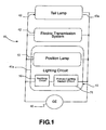
- FIG. 1 shows a block diagram for illustrating the configuration of the bicycle lighting system in which one embodiment of the present invention is adopted;
- FIG. 2 shows a circuit diagram for illustrating the configuration of the lighting circuit thereof; and
- FIG. 3 shows a block diagram for illustrating the configuration of the electric transmission system.
- In FIG. 1, a
bicycle lighting system 10 in which one embodiment of the present invention is adopted comprises a bicycle dynamo in the form of ahub dynamo 40 provided on the bicycle hub shaft, for example, alighting circuit 41 that functions as a front lamp, anelectric transmission system 42 that works as an operating section to be connected in parallel to thelighting circuit 41 for thehub dynamo 40, and atail lamp 43 that works as the operating section. The hub dynamo 40 outputs AC based on bicycle travel, supplying electricity to thelighting circuit 41,electric transmission system 42, andtail lamp 43 on the bicycle. - The
lighting circuit 41 comprises alamp case 41a that can be secured to a lamp stay provided at on the front fork of the bicycle, for example. Thelamp case 41a contains, as illustrated in FIG. 1 and 2, a rectifyingcircuit 50 wherein AC output from thehub dynamo 40 undergoes full-wave rectification and theprimary lighting circuit 51, which is to be a front lamp, using at least one first light emitting diode LED1 that is arranged to always receive electricity outputted from the rectifyingcircuit 50. Furthermore, thelamp case 41 a contains a position lamp (one example of a supplementary lighting circuit) 52, which is the operating section. - Hence, in this embodiment, the operating section comprises the
supplementary lighting circuit 52, theelectric transmission system 42 and thetail lamp 43. - The rectifying
circuit 50 comprises four diodes D1-D4 that are bridge-connected, having positive and negative terminals. - The
primary lighting circuit 51 comprises resistance R1 for adjusting voltage and the current connected to the positive terminal in the rectifyingcircuit 50 and the first light emitting diode LED1 wherein the resistance R1 is connected to the anode. The cathode in the first light emitting diode LED1 is connected to the positive terminal in the rectifyingcircuit 50. The first light emitting diode LED1 is a power LED for radiating white light output at approximately 3 W, for example, and the forward voltage thereof is 3.5 V, for example. The first light emitting diode LED1 and rectifyingcircuit 50 enable output voltage from thehub dynamo 40 to be clamped to a clamp voltage Vc in thelighting system 10. In the clamp voltage Vc at this time, wherein the forward voltage of each diode D1-D4 is Vd, and the forward voltage of the first light emitting diode LED1 is Ved, the clamp voltage Vc is represented as follows:
- Here, if the forward voltage of each diode D1-D4 is 0.6V, for example, the clamp voltage Vc will be 4.7V.
- Consequently, in this
lighting system 10, output voltage from thehub dynamo 40 is always within 4.7 V, which never increases beyond the clamp voltage Vc. - The
position lamp 52 is connected in parallel to theprimary lighting circuit 51. Theposition lamp 52 comprises resistance R2 for adjusting voltage and the current connected to the positive terminal in the rectifyingcircuit 50 and the second light emitting diode LED2 wherein the resistance R2 is connected to the anode. The cathode in the second light emitting diode LED2 is connected to the positive terminal in the rectifyingcircuit 50. The forward voltage of the second light emitting diode LED2 is lower than the forward voltage of the first light emitting diode LED1 (3.5 V, for example), approximately 2 V, for example. The second light emitting diode LED2 is a power LED for radiating white light output at approximately 0.01-1.0 W, for example. Resistance R2 is a larger resistance value than resistance R1, so clamp voltage is not lowered by the second semiconductor diode LED2 by arranging the forward voltage to be approximately 2 V. - The
electric transmission system 42, as illustrated in FIG. 3, comprises astorage element 60 consisting of a large-capacity capacitor (condenser) such as an electric bi-layer capacitor, for example, to control voltage fluctuation when stopped, amotor driver 61 operated by electricity from thestorage element 60, atransmission controlling section 62 to control themotor driver 61, and atransmission motor 63 operated by themotor driver 61. Thetransmission controlling section 62 outputs a motor drive signal to themotor driver 61 with a transmission signal from the transmission switch provided in the handlebars of the bicycle, for example. In such an electric transmission system, conventionally, a voltage-controlling circuit such as a regulator is provided to maintain voltage on the input side of the apparatus. However, with the present embodiment, the first light emitting diode LED1, which is arranged to always receive electricity outputted from the rectifyingcircuit 50, or the rectifyingcircuit 50 clamps output voltage from thehub dynamo 40, thereby controlling it within the clamp voltage, and consequently, such a voltage-controlling circuit is not needed in theelectric transmission system 42. - As illustrated in FIG. 2 and 3, the
tail lamp 43 comprises atail lamp case 43a that can be secured to the rear section of the bicycle. Furthermore, thetail lamp 43 comprises a resistance R3 for adjusting voltage and a current connected to the positive terminal in the rectifyingcircuit 50 contained in thetail lamp case 43a as well as a third light emitting diode LED3 wherein resistance R3 is connected to the anode. The third light emitting diode LED3 is a power LED for radiating red light output at approximately 0.01-1.0 W, for example. The forward voltage of the third light emitting diode LED3 is also approximately 2 V and lower than the first light emitting diode LED1. - In a
lighting system 10 configured in this manner, if a current with an electric potential flows in excess of the forward voltage (2 V, for example) of the second and third light emitting diodes LED2, LED3 from the rectifyingcircuit 50, theposition lamp 52 andtail lamp 43 will light up. However, the current does not flow into the first light emitting diode LED1 in thelighting circuit 41, so the first light emitting diode LED1 does not light up. Moreover, if a current with an electric potential flows in excess of the forward voltage of the first light emitting diode LED1 from the rectifyingcircuit 50, the first light emitting diode LED1 lights up as a headlamp in theprimary lighting circuit 51 oflighting circuit 41. If the current flows into the first light emitting diode LED1, the current flows inlighting circuit 41, so output voltage from thehub dynamo 40 is clamped to the clamp voltage Vc while the first light emitting diode LED1 is on, because the first light emitting diode LED1 always receives electricity outputted from the rectifyingcircuit 50. Consequently, the output voltage from thehub dynamo 40 does not increase beyond the clamp voltage Vc at high speeds, so excessive voltage is not applied to theposition lamp 52,electric transmission system 42, ortail lamp 43. - Here, because voltage in the
overall lighting system 10 is clamped to the first light emitting diode LED1 for lighting, it is not necessary to provide a voltage-controlling circuit for each operating section. Consequently, in thebicycle lighting system 10, the apparatus for controlling voltage can be simplified. - Modifications and improvements can be incorporated without departing from the scope of the invention. For example:
- (a) In the previous embodiment, the light emitting diode is used for the
position lamp 52 ortail lamp 43 as the operating section, but an ordinary light bulb can be used; and - (b) In the previous embodiment, the
position lamp 52,electric transmission system 42, andtail lamp 43 are illustrated as the operating section, but the operating section includes all electrical devices operated with electricity from the dynamo.
Claims (5)
- A bicycle lighting system (10) comprising:a rectifying circuit (50) for rectifying electricity generated by a bicycle dynamo (40);a lighting circuit (41) comprising a primary lighting circuit (51) connected to said rectifying circuit (50), said primary lighting circuit (51) having at least one first light emitting diode (LED1) arranged to always receive electricity outputted from said rectifying circuit (50); andan operating section connected in parallel with said lighting circuit (41) for said bicycle dynamo (40) to be operated by electricity from the dynamo (40).
- A bicycle lighting system (10) according to Claim 1, wherein said operating section comprises a supplementary lighting circuit (52) comprising a second light emitting diode (LED2), wherein the forward voltage of the second light emitting diode (LED2) is lower than that of said first light emitting diode (LED1).
- A bicycle lighting system (10) according to Claims 1 or 2, wherein said operating section comprises an electric transmission controlling system (42) for controlling the bicycle electric transmission apparatus.
- A bicycle lighting system (10) according to Claim 3, wherein said electric transmission system (42) comprises a storage element (60) for storing rectified electricity.
- A bicycle lighting system (10) according to any one of Claims 1 to 4, wherein said operating section comprises a tail lamp (43) connected to the rear section of the bicycle, the tail lamp (43) comprising a third light emitting diode (LED3), the forward voltage of the third light emitting diode (LED3) being lower than that of said first light emitting diode (LED1).
Applications Claiming Priority (1)
| Application Number | Priority Date | Filing Date | Title |
|---|---|---|---|
| JP2006126227A JP4168061B2 (en) | 2006-04-28 | 2006-04-28 | Bicycle lighting system |
Publications (2)
| Publication Number | Publication Date |
|---|---|
| EP1849692A1 true EP1849692A1 (en) | 2007-10-31 |
| EP1849692B1 EP1849692B1 (en) | 2010-04-07 |
Family
ID=38210388
Family Applications (1)
| Application Number | Title | Priority Date | Filing Date |
|---|---|---|---|
| EP07250825A Ceased EP1849692B1 (en) | 2006-04-28 | 2007-02-28 | Bicycle lighting system |
Country Status (5)
| Country | Link |
|---|---|
| US (1) | US7459857B2 (en) |
| EP (1) | EP1849692B1 (en) |
| JP (1) | JP4168061B2 (en) |
| CN (1) | CN100567071C (en) |
| DE (1) | DE602007005713D1 (en) |
Cited By (1)
| Publication number | Priority date | Publication date | Assignee | Title |
|---|---|---|---|---|
| US9296440B2 (en) | 2011-08-16 | 2016-03-29 | Trek Bicycle Corporation | Lighted bicycle wheel hub assembly |
Citations (2)
| Publication number | Priority date | Publication date | Assignee | Title |
|---|---|---|---|---|
| WO2002036420A1 (en) * | 2000-10-18 | 2002-05-10 | Ajg Industrie-Batterien Gmbh Geschäftsführer Jürgen Gräfke | Switched led headlight reflector |
| US20050243545A1 (en) * | 2002-06-11 | 2005-11-03 | Akidenki Kabushikigaisya | Head lamp of a bicycle and head lamp electric circuit |
Family Cites Families (8)
| Publication number | Priority date | Publication date | Assignee | Title |
|---|---|---|---|---|
| EP0460585B1 (en) * | 1990-06-07 | 1993-12-22 | BISY Bike Systems Industrielle Fertigung von Fahrradteilen GmbH | Bicycle lighting equipment with dynamo |
| DE4324779A1 (en) * | 1993-07-23 | 1994-03-03 | Personen Und Werkschutz Gmbh I | Signal display indicating malfunction of bicycle's lamps - has green LED electrically in series with rear lamp and mounted on headlamp casing |
| DE9313820U1 (en) * | 1993-09-13 | 1994-01-20 | Gebensleben, Enno, 22547 Hamburg | Bicycle lights |
| JP3573723B2 (en) | 2001-06-29 | 2004-10-06 | 株式会社シマノ | Gear change control device for bicycle |
| JP3654876B2 (en) * | 2002-07-15 | 2005-06-02 | 株式会社シマノ | Bicycle lighting device drive |
| JP3727292B2 (en) * | 2002-08-20 | 2005-12-14 | 株式会社シマノ | Bicycle electrical equipment drive device |
| JP3845092B2 (en) * | 2004-01-16 | 2006-11-15 | 株式会社シマノ | Bicycle lighting device |
| JP2006325372A (en) * | 2005-05-20 | 2006-11-30 | Shimano Inc | Dc power supply unit for human-powered vehicle |
-
2006
- 2006-04-28 JP JP2006126227A patent/JP4168061B2/en not_active Expired - Fee Related
- 2006-12-18 CN CNB2006101717040A patent/CN100567071C/en not_active Expired - Fee Related
- 2006-12-28 US US11/646,454 patent/US7459857B2/en not_active Expired - Fee Related
-
2007
- 2007-02-28 EP EP07250825A patent/EP1849692B1/en not_active Ceased
- 2007-02-28 DE DE602007005713T patent/DE602007005713D1/en active Active
Patent Citations (2)
| Publication number | Priority date | Publication date | Assignee | Title |
|---|---|---|---|---|
| WO2002036420A1 (en) * | 2000-10-18 | 2002-05-10 | Ajg Industrie-Batterien Gmbh Geschäftsführer Jürgen Gräfke | Switched led headlight reflector |
| US20050243545A1 (en) * | 2002-06-11 | 2005-11-03 | Akidenki Kabushikigaisya | Head lamp of a bicycle and head lamp electric circuit |
Cited By (1)
| Publication number | Priority date | Publication date | Assignee | Title |
|---|---|---|---|---|
| US9296440B2 (en) | 2011-08-16 | 2016-03-29 | Trek Bicycle Corporation | Lighted bicycle wheel hub assembly |
Also Published As
| Publication number | Publication date |
|---|---|
| CN100567071C (en) | 2009-12-09 |
| DE602007005713D1 (en) | 2010-05-20 |
| US7459857B2 (en) | 2008-12-02 |
| CN101062698A (en) | 2007-10-31 |
| EP1849692B1 (en) | 2010-04-07 |
| JP4168061B2 (en) | 2008-10-22 |
| JP2007296960A (en) | 2007-11-15 |
| US20070252537A1 (en) | 2007-11-01 |
Similar Documents
| Publication | Publication Date | Title |
|---|---|---|
| JP5089193B2 (en) | Light emitting device | |
| US7883248B2 (en) | Bicycle illumination apparatus | |
| US8841862B2 (en) | LED driving system and method for variable voltage input | |
| JP5006165B2 (en) | Vehicle lighting | |
| EP2885575B1 (en) | Method and apparatus to control light intensity as voltage fluctuates | |
| US8049436B2 (en) | Dimmer and lighting apparatus | |
| US8836239B2 (en) | LED lighting device and illumination apparatus including same | |
| EP1555195B1 (en) | Bicycle lighting device | |
| EP1849692B1 (en) | Bicycle lighting system | |
| JP4995777B2 (en) | LED lighting device, LED lamp, and LED lighting method | |
| US20030006717A1 (en) | Multiregulator circuit and lamp | |
| US6768273B2 (en) | Dynamo control circuit for a bicycle | |
| US8134296B2 (en) | Regulating circuitry for automobile light systems | |
| JP2017033892A (en) | Lighting circuit, lighting fixture for vehicle | |
| EP3281270B1 (en) | Load powered via supply or re-chargeable source | |
| KR101545153B1 (en) | Driving apparatus for LED warning lamp and LED working lamp by using the same | |
| EP2775795B1 (en) | Dimmable LED reading light unit, arrangement of power supply and dimmable LED reading light unit and method of replacing a dimmable light unit by a dimmable LED reading light unit | |
| JP5940015B2 (en) | Power supply device, LED lighting device, and in-vehicle headlamp system | |
| EP1849693B1 (en) | Bicycle overvoltage protection device | |
| US7728560B2 (en) | Power system for producing low power DC voltage at a level above a peak value of an AC input to the system | |
| US20180070418A1 (en) | Voltage-dependent operation of individual light sources | |
| JP5386421B2 (en) | Lighting apparatus and light emitting module used therefor | |
| JP4506593B2 (en) | Lighting device | |
| JP2023094061A (en) | electrical equipment | |
| JP2005285531A (en) | LED signal lamp |
Legal Events
| Date | Code | Title | Description |
|---|---|---|---|
| PUAI | Public reference made under article 153(3) epc to a published international application that has entered the european phase |
Free format text: ORIGINAL CODE: 0009012 |
|
| AK | Designated contracting states |
Kind code of ref document: A1 Designated state(s): AT BE BG CH CY CZ DE DK EE ES FI FR GB GR HU IE IS IT LI LT LU LV MC NL PL PT RO SE SI SK TR |
|
| AX | Request for extension of the european patent |
Extension state: AL BA HR MK YU |
|
| 17P | Request for examination filed |
Effective date: 20071108 |
|
| 17Q | First examination report despatched |
Effective date: 20071214 |
|
| AKX | Designation fees paid |
Designated state(s): DE IT NL |
|
| GRAP | Despatch of communication of intention to grant a patent |
Free format text: ORIGINAL CODE: EPIDOSNIGR1 |
|
| GRAS | Grant fee paid |
Free format text: ORIGINAL CODE: EPIDOSNIGR3 |
|
| GRAA | (expected) grant |
Free format text: ORIGINAL CODE: 0009210 |
|
| AK | Designated contracting states |
Kind code of ref document: B1 Designated state(s): DE IT NL |
|
| REF | Corresponds to: |
Ref document number: 602007005713 Country of ref document: DE Date of ref document: 20100520 Kind code of ref document: P |
|
| REG | Reference to a national code |
Ref country code: NL Ref legal event code: T3 |
|
| PLBE | No opposition filed within time limit |
Free format text: ORIGINAL CODE: 0009261 |
|
| STAA | Information on the status of an ep patent application or granted ep patent |
Free format text: STATUS: NO OPPOSITION FILED WITHIN TIME LIMIT |
|
| 26N | No opposition filed |
Effective date: 20110110 |
|
| PGFP | Annual fee paid to national office [announced via postgrant information from national office to epo] |
Ref country code: IT Payment date: 20120217 Year of fee payment: 6 |
|
| PGFP | Annual fee paid to national office [announced via postgrant information from national office to epo] |
Ref country code: NL Payment date: 20160111 Year of fee payment: 10 |
|
| PG25 | Lapsed in a contracting state [announced via postgrant information from national office to epo] |
Ref country code: IT Free format text: LAPSE BECAUSE OF NON-PAYMENT OF DUE FEES Effective date: 20140228 |
|
| REG | Reference to a national code |
Ref country code: NL Ref legal event code: MM Effective date: 20170301 |
|
| PG25 | Lapsed in a contracting state [announced via postgrant information from national office to epo] |
Ref country code: NL Free format text: LAPSE BECAUSE OF NON-PAYMENT OF DUE FEES Effective date: 20170301 |
|
| PGFP | Annual fee paid to national office [announced via postgrant information from national office to epo] |
Ref country code: DE Payment date: 20190212 Year of fee payment: 13 |
|
| PGFP | Annual fee paid to national office [announced via postgrant information from national office to epo] |
Ref country code: DE Payment date: 20190212 Year of fee payment: 13 |
|
| REG | Reference to a national code |
Ref country code: DE Ref legal event code: R119 Ref document number: 602007005713 Country of ref document: DE |
|
| PG25 | Lapsed in a contracting state [announced via postgrant information from national office to epo] |
Ref country code: DE Free format text: LAPSE BECAUSE OF NON-PAYMENT OF DUE FEES Effective date: 20200901 |