EP1849312B1 - Reception en diversite iterative - Google Patents
Reception en diversite iterative Download PDFInfo
- Publication number
- EP1849312B1 EP1849312B1 EP06735096.7A EP06735096A EP1849312B1 EP 1849312 B1 EP1849312 B1 EP 1849312B1 EP 06735096 A EP06735096 A EP 06735096A EP 1849312 B1 EP1849312 B1 EP 1849312B1
- Authority
- EP
- European Patent Office
- Prior art keywords
- symbols
- symbol
- type
- data sequence
- soft values
- Prior art date
- Legal status (The legal status is an assumption and is not a legal conclusion. Google has not performed a legal analysis and makes no representation as to the accuracy of the status listed.)
- Active
Links
- 239000002131 composite material Substances 0.000 claims description 37
- 238000000034 method Methods 0.000 claims description 37
- 238000012937 correction Methods 0.000 claims description 18
- 238000004364 calculation method Methods 0.000 claims description 11
- 238000005070 sampling Methods 0.000 claims description 3
- 238000012545 processing Methods 0.000 description 47
- 239000013598 vector Substances 0.000 description 38
- 230000001934 delay Effects 0.000 description 15
- 238000010586 diagram Methods 0.000 description 15
- 230000008569 process Effects 0.000 description 8
- 230000008901 benefit Effects 0.000 description 7
- 238000004891 communication Methods 0.000 description 5
- 230000002452 interceptive effect Effects 0.000 description 4
- 238000013507 mapping Methods 0.000 description 4
- 230000003321 amplification Effects 0.000 description 3
- 238000013459 approach Methods 0.000 description 3
- 238000006243 chemical reaction Methods 0.000 description 3
- 230000000694 effects Effects 0.000 description 3
- 238000003199 nucleic acid amplification method Methods 0.000 description 3
- 230000010363 phase shift Effects 0.000 description 3
- 238000001228 spectrum Methods 0.000 description 3
- 238000001914 filtration Methods 0.000 description 2
- 230000006872 improvement Effects 0.000 description 2
- 230000001360 synchronised effect Effects 0.000 description 2
- 101100458289 Drosophila melanogaster msps gene Proteins 0.000 description 1
- 238000007476 Maximum Likelihood Methods 0.000 description 1
- 102000005717 Myeloma Proteins Human genes 0.000 description 1
- 108010045503 Myeloma Proteins Proteins 0.000 description 1
- 238000007792 addition Methods 0.000 description 1
- 239000000654 additive Substances 0.000 description 1
- 230000000996 additive effect Effects 0.000 description 1
- OXNGKCPRVRBHPO-XLMUYGLTSA-N alpha-L-Fucp-(1->2)-beta-D-Galp-(1->3)-[alpha-L-Fucp-(1->4)]-beta-D-GlcpNAc Chemical compound O[C@H]1[C@H](O)[C@H](O)[C@H](C)O[C@H]1O[C@H]1[C@H](O[C@H]2[C@@H]([C@@H](CO)O[C@@H](O)[C@@H]2NC(C)=O)O[C@H]2[C@H]([C@H](O)[C@H](O)[C@H](C)O2)O)O[C@H](CO)[C@H](O)[C@@H]1O OXNGKCPRVRBHPO-XLMUYGLTSA-N 0.000 description 1
- 230000005540 biological transmission Effects 0.000 description 1
- 230000008859 change Effects 0.000 description 1
- 238000010276 construction Methods 0.000 description 1
- 238000007796 conventional method Methods 0.000 description 1
- 230000003111 delayed effect Effects 0.000 description 1
- 230000001066 destructive effect Effects 0.000 description 1
- 238000001514 detection method Methods 0.000 description 1
- 238000005516 engineering process Methods 0.000 description 1
- 238000013178 mathematical model Methods 0.000 description 1
- 238000012986 modification Methods 0.000 description 1
- 230000004048 modification Effects 0.000 description 1
- 230000000644 propagated effect Effects 0.000 description 1
- 238000007493 shaping process Methods 0.000 description 1
- 238000006467 substitution reaction Methods 0.000 description 1
- 230000036962 time dependent Effects 0.000 description 1
- 238000013519 translation Methods 0.000 description 1
Images


Classifications
-
- H—ELECTRICITY
- H04—ELECTRIC COMMUNICATION TECHNIQUE
- H04B—TRANSMISSION
- H04B7/00—Radio transmission systems, i.e. using radiation field
- H04B7/14—Relay systems
- H04B7/15—Active relay systems
- H04B7/185—Space-based or airborne stations; Stations for satellite systems
- H04B7/1853—Satellite systems for providing telephony service to a mobile station, i.e. mobile satellite service
- H04B7/18532—Arrangements for managing transmission, i.e. for transporting data or a signalling message
- H04B7/18534—Arrangements for managing transmission, i.e. for transporting data or a signalling message for enhancing link reliablility, e.g. satellites diversity
-
- H—ELECTRICITY
- H04—ELECTRIC COMMUNICATION TECHNIQUE
- H04B—TRANSMISSION
- H04B7/00—Radio transmission systems, i.e. using radiation field
- H04B7/02—Diversity systems; Multi-antenna system, i.e. transmission or reception using multiple antennas
- H04B7/04—Diversity systems; Multi-antenna system, i.e. transmission or reception using multiple antennas using two or more spaced independent antennas
-
- H—ELECTRICITY
- H04—ELECTRIC COMMUNICATION TECHNIQUE
- H04L—TRANSMISSION OF DIGITAL INFORMATION, e.g. TELEGRAPHIC COMMUNICATION
- H04L1/00—Arrangements for detecting or preventing errors in the information received
- H04L1/004—Arrangements for detecting or preventing errors in the information received by using forward error control
- H04L1/0045—Arrangements at the receiver end
- H04L1/0047—Decoding adapted to other signal detection operation
- H04L1/0048—Decoding adapted to other signal detection operation in conjunction with detection of multiuser or interfering signals, e.g. iteration between CDMA or MIMO detector and FEC decoder
-
- H—ELECTRICITY
- H04—ELECTRIC COMMUNICATION TECHNIQUE
- H04L—TRANSMISSION OF DIGITAL INFORMATION, e.g. TELEGRAPHIC COMMUNICATION
- H04L1/00—Arrangements for detecting or preventing errors in the information received
- H04L1/004—Arrangements for detecting or preventing errors in the information received by using forward error control
- H04L1/0045—Arrangements at the receiver end
- H04L1/0047—Decoding adapted to other signal detection operation
- H04L1/005—Iterative decoding, including iteration between signal detection and decoding operation
-
- H—ELECTRICITY
- H04—ELECTRIC COMMUNICATION TECHNIQUE
- H04L—TRANSMISSION OF DIGITAL INFORMATION, e.g. TELEGRAPHIC COMMUNICATION
- H04L1/00—Arrangements for detecting or preventing errors in the information received
- H04L1/004—Arrangements for detecting or preventing errors in the information received by using forward error control
- H04L1/0056—Systems characterized by the type of code used
- H04L1/0064—Concatenated codes
-
- H—ELECTRICITY
- H04—ELECTRIC COMMUNICATION TECHNIQUE
- H04L—TRANSMISSION OF DIGITAL INFORMATION, e.g. TELEGRAPHIC COMMUNICATION
- H04L1/00—Arrangements for detecting or preventing errors in the information received
- H04L1/004—Arrangements for detecting or preventing errors in the information received by using forward error control
- H04L1/0056—Systems characterized by the type of code used
- H04L1/0071—Use of interleaving
-
- H—ELECTRICITY
- H04—ELECTRIC COMMUNICATION TECHNIQUE
- H04L—TRANSMISSION OF DIGITAL INFORMATION, e.g. TELEGRAPHIC COMMUNICATION
- H04L1/00—Arrangements for detecting or preventing errors in the information received
- H04L1/02—Arrangements for detecting or preventing errors in the information received by diversity reception
- H04L1/06—Arrangements for detecting or preventing errors in the information received by diversity reception using space diversity
- H04L1/0618—Space-time coding
- H04L1/0631—Receiver arrangements
Definitions
- Traditional path diversity schemes take advantage of diversity associated with signals transmitted over multiple paths, to improve the performance of a communication system.
- Information originating from a single data source can be intentionally or unintentionally propagated over multiple paths before arriving at a destination receiver.
- the propagation of a signal over the multiple paths causes different "versions" of the signal to arrive at the receiver at different time offsets, and at approximately the same frequency.
- the multiple paths may occur due to signal reflections, may occur due to delays attributable to one or more signal processing devices, such as repeaters, interposed between the transmitter and receiver, or due to some combination of physical paths and delays through signal processing devices.
- the difference in time of arrival associated with the different signal paths increases as the physical distances traversed by multiple signal paths increase.
- the receiver may be able to benefit from the existence of such multiple paths, or path diversity, if the receiver is able to properly process each of the delayed versions of the transmitted signal.
- the optimum demodulator of a multipath signal is the well known Maximum Likelihood Sequence Estimation, which is commonly implemented using the Viterbi Algorithm.
- This approach is practical when the difference in the path delays between the paths is a relatively small number of symbols, e.g., ⁇ 10, but is unpractical for scenarios such as that depicted in Figure 1 where the differential path delay can be thousands of symbols in duration.
- Another approach is the classic RAKE receiver, which is also well known to those of ordinary skill in the art.
- the RAKE receiver provides a good approximation to the optimal receiver when the signal to noise ratio (SNR) is very low, e.g., ⁇ -6 dB. For this reason, the RAKE receiver is commonly used with spread spectrum signals, such as code division multiple access (CDMA) signals. But for higher SNR environments that are common in non-spread spectrum applications, the RAKE receiver is ineffective. Thus, traditional path diversity schemes have been limited in their application.
- SNR signal to noise ratio
- CDMA code division multiple access
- US 2003/0193966 describes a multi-user turbo decoder combining multi-user detection and forward error correction decoding that utilizes iterative decoding of received, interfering signals, and the construction of a decoding tree of the decoder is changed for each iteration of the decoding based on the previous conditional probability estimates of the value of the data bits of each signal making up the received, interfering signals.
- a probability estimate is calculated that the value of the bit in a signal has a certain value for all of the data bits.
- Using the probability estimate a new decoding tree is constructed before each iteration of decoding such that the signal bit having the most reliable estimate is assigned to the lowest or root level of the tree.
- the signal bit having the next most reliable estimate is assigned to the second level of the tree, and so forth, with the signal bit having the least reliable estimate being assigned to the highest level of the tree adjacent the terminating nodes or leaves of the tree.
- Described herein are methods and apparatuses for deriving data from a composite signal involving (a) receiving a composite signal comprising contributions from a plurality of individual signals transmitted over different paths, the plurality of individual signals being used to represent a common data sequence such that each of the individual signals corresponds to a data sequence that is a version of the common data sequence, (b) for each individual signal, calculating soft values of a first type over a block of symbols by taking into account the received composite signal and soft values of a second type, wherein for each symbol, a soft value of the first type is calculated for each possible symbol value of the symbol, (c) generating symbol outputs by taking into account the soft values of the first type from the different individual signals, (d) for each individual signal, calculating soft values of the second type over the block of symbols by taking into account the symbol outputs, wherein for each symbol, a soft value of the second type is calculated for each possible symbol value of the symbol, (e) feeding back the soft values of the second
- the individual signals are transmitted via satellites.
- the individual signals may be sent from different transmitters and received at a common receiver as the composite signal.
- the individual signals are sent from a common transmitter, received initially at different receivers, subsequently combined, then received as the composite signal.
- the individual signals may be combined in the manner to cancel interference signals.
- the soft values of the second type may be set to a constant value, such as zero.
- the corresponding data sequence may be related to the common data sequence by a known relationship.
- the known relationship may comprise a time-shifting function.
- the known relationship may comprise a re-ordering function.
- Generating the symbol outputs may involve, for each individual signal having a corresponding data sequence related to the common data sequence by a known relationship, aligning the soft values of the first type with the common data sequence by applying an inverse of the known relationship, to generate aligned soft values of the first kind, and combining aligned soft values of the first kind from different individual signals to generate the symbol outputs.
- Calculating soft values of the second type may involve, for each individual signal having a corresponding data sequence related to the common data sequence by a known relationship, re-aligning the symbol outputs by applying the known relationship, to generate the soft values of the second kind.
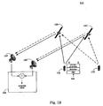
- Fig 1A is a diagram of an illustrative system 100 which includes an Earth station 102 simultaneously transmitting two signals representing a common data sequence using two antennas 104 and 106, via two separate satellites 108 and 110, the signals being received as a composite signal at a user terminal (UT) 112, in accordance with an embodiment of the present invention.
- System 100 thus presents an example of a composite signal comprising contributions from a plurality of individual signals transmitted over different paths, wherein the individual signals are sent from different transmitters and received at a common receiver as a composite signal.
- Earth station 102 is viewed here as the single data source.
- the data is encoded by a forward error correction (FEC) code.
- FEC forward error correction
- the encoded data is used as the common data sequence from which individual signals are generated.
- the common data sequence is optionally re-ordered according to a re-ordering function (described in more detail in subsequent sections) and modulated according to a suitable modulation scheme.
- MPSK Phase Shift Keying
- each individual signal is a modulated signal that represents the common data sequence originating from Earth station 102.
- the two resulting modulated signals are separately upconverted to a suitable radio frequency (RF) and amplified using high power amplifiers (HPA).
- the two upconverted, amplified signals are then separately transmitted using antennas 104 and 106, to satellites 108 and 110, respectively.
- the encoding, modulation, upconversion, and amplification of the two individual signals can be implemented using known techniques familiar to those of ordinary skill in the art.
- the two satellites 108 and 110 are non-processing "bent pipe" satellites in low, medium or geo-synchronous orbits, each satellite being in a distinct orbit slot. Satellites 108 and 110 relay the individual signals from antennas 104 and 106 using the same nominal downlink frequency so the signals arrive at user terminal 112 at the same frequency, exclusive of any Doppler shift or satellite frequency translation error which is not common between all paths. These separate signals thus generally tend to interfere with each other. However, if the signals at the receiver can be properly processed, the diversity paths can be used to increase the signal to noise ratio and improve the link performance.
- User terminal 112 may be implemented as one of a variety of different type of devices, such as a handheld device, a vehicle mounted terminal, or a fixed Earth station.
- user terminal 112 employs a single receive antenna with sufficient beamwidth to be pointed at all signal paths simultaneously, including the signal path from satellite 108 and the signal path from satellite 110.
- User terminal 112 processes the composite signal which comprises contributions from individual signals transmitted over the different paths to take advantage of path diversity and thereby improve link performance.
- L satellites there may be L paths in the multipath channel, L being a positive integer that may be greater than two.
- the present invention is not necessarily limited to satellite communication applications, even though satellite systems are used here to illustrate various embodiments of the invention.
- Fig 1B is a diagram of an illustrative system 150 which includes a user terminal (UT) 152 transmitting a signal on different paths via two separate satellites 160 and 162, resulting in two signals being received at two separate antennas 164 and 166, wherein the signals are combined at an Earth station 168 to form a composite signal, in accordance with an embodiment of the present invention.
- System 150 thus presents an example of a composite signal comprising contributions from a plurality of individual signals transmitted over different paths, wherein the individual signals are sent from a common transmitter and received initially at different receivers, subsequently combined, and then received as a composite signal.
- System 150 presents a technique that can be used for canceling out undesired interference signals by adding received signals together.
- the desired signals (shown in solid lines) are transmitted from user terminal 152, over multiple paths via satellites 160 and 162, to antennas 164 and 166.
- Undesired interference signals (shown in dotted lines) are transmitted from an interfering user terminal 170, over multiple paths via satellites 160 and 162, to antennas 164 and 166.
- the undesired interference uses the same transmission frequency as the desired signal.
- the desired signals and interference signals arrive at antennas 164 and 166 of Earth station 168 at the same frequency.
- the signal received at antenna 164 from satellite 160 has both a desired component and an interferer component.
- the signal received at antenna 166 from satellite 162 has both a desired component and an interferer component.
- Earth station 168 processes these two received signals from antennas 164 and 166 and combines them such that their interferer components cancel each other out. Specifically, Earth station 168 adjusts the relative phase, relative timing, relative amplitude, and possibly other attributes of the two received signals from antennas 164 and 166 such that their respective interferer components are 180 degrees out of phase and equal in magnitude. Thus, when the two received signals are combined, their respective interferer components cancel each other out (by destructive interference). What remains is a composite signal that is substantially free of the interference from user terminal 170. This composite signal is thus comprised of contributions from a plurality of individual signals transmitted over different paths, wherein the individual signals are sent from a common, desired transmitter, which is user terminal 152. The composite signal can then be processed using the innovative path diversity approaches described in various embodiments of the present invention.
- the equipment associated with Earth station 168 comprises low noise amplifiers (LNA) 180 and 182, down converters (DC) 184 and 186, parameter adjustment (Phase Amp Time Adjust) blocks 188 and 190, and signal combiner 192.
- LNA 180 amplifies the signal received from antenna 164.
- DC 184 down converts this amplified signal.
- Phase Amp Time Adjust block 188 performs proper phase, amplitude, and time adjustments to the down-converted signal.
- the resulting signal is presented to one input of signal combiner 192.
- Similar processing is performed on the signal received from antenna 166, using LNA 182, DC 186, Phase Amp Time Adjust block 190, to generate a resulting signal that is presented to the other input of signal combiner 192. Processing described above adjusts the two resulting signals such that their interferer components are of equal magnitude and 180 degrees out of phase.
- Combiner 192 then adds the two signals together so that their interferer components cancel each other out.
- the two satellites 160 and 162 of system 150 are non-processing "bent pipe" satellites in low, medium or geo-synchronous orbits, each satellite being in a distinct orbit slot. Satellites 160 and 162 relay the signal from user terminal 152, along with the undesired signals from interferer user terminal 170, using the same nominal downlink frequency so the signals arrive antennas 164 and 166 at the same frequency, exclusive of any Doppler shift which is not common between all paths. According the present embodiment of the invention, the undesired signals from interferer user terminal 170 are canceled out with one another at Earth station 168. Further, the desired signals from user terminal 152 are processed at Earth station 168 to take advantage of path diversity and thereby improve link performance.
- L satellites there may be L paths in the multipath channel, L being a positive integer that may be greater than two.
- the difference in the path delays between various paths can be many milliseconds, even more than 10 milliseconds.
- the time arrival difference between paths can be thousands of symbols in duration. The techniques described herein allows path diversity to be exploited even when delay spread between the diversity paths is large relative to the symbol period.
- Fig. 2 is a basic block diagram of an example transmitter structure 200 suitable for generating a plurality of individual signals that can be transmitted over different paths, according to one embodiment of the present invention.
- the plurality of individual signals represent a common data sequence such that each individual signal corresponds to a version of the common data sequence. While Fig. 2 illustrates an example where three individual signals are generated, the number of individual signals can be a number other than three. That is, transmit structure 200 can be implemented to generate L individual signals, where L is any positive integer.
- transmitter structure 200 may be configured in Earth station 102 to generate two individual signals, which are transmitted by antennas 104 and 106.
- transmitter structure 200 comprises a forward error correction encoder (FEC) 204, a set of re-order blocks (RE-ORDER) 206B-C, a set of modulators (MOD) 208A-C, a set of upconverter and high power amplifiers (UC and HPA) 210A-C, and a set of outputs 212A-C.
- FEC forward error correction encoder
- RE-ORDER set of re-order blocks
- MOD modulators
- UC and HPA upconverter and high power amplifiers
- outputs 212A-C Operations of the various components of transmitter structure 200 is described in further detail below.
- An input 202 accepts a data sequence to be processed by transmitter structure 200.
- Input 202 may be implemented in different ways.
- input 202 may comprise a digital interface to a data source, such as a buffer (not shown).
- FEC encoder 204 encodes the data sequence to produce an encoded data sequence.
- the encoded data sequence is used as a common data sequence to generate individual data sequences, each of which is a "version" of the common data sequence.
- One method of generating these individual data sequence is by using optional re-order blocks 206B-C. If implemented, each of the re-order blocks 206B-C re-orders the encoded sequence according to a known re-ordering function, to generate a differently re-ordered sequence. Alternatively, no re-ordering is performed, in which case the individual signals remain ordered in the same way. Even if no re-ordering is applied, the individual signals can later become offset in time from one another as they are transmitted over different paths and experience different path delays.
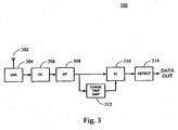
- Fig. 3 is a basic block diagram of an example receiver structure 300 suitable for processing a composite signal comprising contributions from individual signals transmitted over multiple paths, according to one embodiment of the present invention.
- receiver structure 300 may be implemented in user terminal 112 to process the composite signal received from satellites 108 and 110.
- portions of receiver structure 300 may be implemented in Earth station 168 to process the composite signal generated from the combining of signals received from satellites 160 and 162.
- receiver structure 300 comprises a low noise amplifier (LNA) 304, a down converter (DC) 306, a match filter (MF) 308, an iterative combiner (IC) 310, a processing block (PHASE TIME AMP) 312, and a data detector (DETECT) 314.
- LNA low noise amplifier
- DC down converter
- MF match filter
- IC processing block
- DETECT data detector
- An input 302 accepts a composite signal to be processed by receiver structure 300.
- Input 302 may be implemented in different ways.
- input 302 is shown as an antenna receiving the composite signal. In other implementations, input 302 may simply be a port through which the composite signal is delivered from another device.
- Low noise amplifier 304 amplifies the composite signal.
- Down convert 306 brings the signal down to baseband.
- the signal, now complex is filtered by an appropriate match filter 308 and sampled at the rate of once per symbol.
- the result is a sampled complex output z(n), which is presented to iter
- L L different paths
- Facilities such as low noise amplifier 304 and down converter 306 of receiver structure 300 may perform appropriate low noise amplification and down conversion on the composite signal.
- p(t) is the pulse shaping which can be a Square Root Raised Cosine (SRRC) pulse shape
- ⁇ l is the additional time delay of the l th path with respect to path number 0.
- Path number zero is defined to be the path with
- coefficients w l and ⁇ l can be separately determined via conventional methods well known to one of ordinary skill in the art.
- coefficients w l and ⁇ l may be determined by PHASE TIME AMP processing block 312 of receiver structure 300.
- a re-ordering of the sequence a 0 (n) to result in the sequence a l (n) can be used.
- such re-ordering may be applied on the transmit side during generation of the individual signals, by using re-order blocks 206B-C shown in Fig. 2 . This allows one to use re-ordered symbol sequences for the subsequent diversity paths.
- the received signal levels were the same and small random frequency error was introduced to simulate the small differences in received frequency of the two paths.
- the performance with iterative combining is nearly 3 dB better than the no diversity case, and unlike the RAKE receiver, it performs very well at large SNRs.
- the APP Soft Outputs for the last k ⁇ symbols in the a l (n) stream will have a lower reliability to them than the other symbols.
- this information will be combined with the information on the same symbols from the a 0 (n) stream, which does not have a low reliability, to yield a significant improvement on the reliability of combined Soft Outputs for the symbols a(B-k l )...a(B-k1).
- Still the reliability of these symbols will be less than the reliability of combined Soft Outputs for symbols a(0)...a(B-k l -1).
- B which is much larger than k ⁇ .
- the processing block starts k ⁇ symbols before the arrival a o (0) symbol.
- This allows the iterative combiner to generate combined Soft Outputs for the last k ⁇ symbols in the previous block as well as the B symbols in the current block.
- a total of B + k ⁇ combined Soft Outputs are generated for each processing block.
- Consecutive processing blocks will have an overlap of k ⁇ symbols in the combined Soft Outputs.
- the combined Soft Outputs for last k ⁇ symbols of the previous block which have a reduced reliability as compared to the first B-k ⁇ symbols in the previous block, can be replaced with the combined Soft Outputs for the first k ⁇ symbols of the current block.
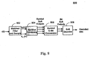
- the matched filter and sample block 802 takes the received baseband complex signal, r(t), and generates the sample stream into iterative combiner 804 as defined in (12). Iterative combiner 804 performs all iterations of the combining as described previously and then provides four soft outputs per symbol, one for each of the four possible symbol values (QPSK modulation is assumed here).
- the symbol-to-bit converter 806 takes the soft outputs for each of the 4 possible symbol values and generates soft decisions for each of the 2 bits in the QPSK signal. In other words, symbol-to-bit converter 806 converts symbol soft outputs to bit soft outputs. The bit soft outputs are then used as inputs to the FEC decoder. There is no feedback from the FEC decoder to the iterative combiner.
- LLR log likelihood ratio
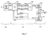
- Fig. 9 is a block diagram depicting the operations of match filter 308, iterative combiner 310, and data detector 314, as modified to implement integrated iterative combining and FEC decoding, in accordance with an embodiment of the present invention.
- match filter 308 comprises match filter and sampler 902.
- Iterative combiner 310 comprises APP block 904, summation block 906, and various permutation and inverse permutation functions.
- Data detector 314 comprises symbol-to-bit converter 908, soft FEC decoder 910, and symbol-to-bit converter 912.
- the structure shown in Fig. 9 is configured to integrate iterative combining functions with FEC decoding functions.
- matched filter and sample block 902 takes the received baseband complex signal, r(t), and generates the sample stream sent to iterative combiner 310 as defined in (12). Iterative combiner 310 uses these input samples and performs one iteration of the combining with all components of the soft inputs vectors SI (a 0 )... SI (a L-1 ) initialized to 0 or some other constant.
- the output of iterative combiner 310 are the vectors SO'(a) (generated by summation block 906), one for each symbol in the block, whose components contain soft information related to the probability that the symbol, a, takes on the value j,j ⁇ [0..M-1]. These values are symbol soft outputs.
- Bit-to-symbol converter 912 takes the extrinsic information on the bits, L e (b) and converts it to soft information on each of the symbols. In other words, decoded bit soft outputs are converted to decoded symbol soft outputs. These decoded symbol soft outputs are the vectors SO "(a), one for each symbol in the block, whose components contain soft information related to the probability that the symbol a takes on the value j,j ⁇ [0..M-1].
Claims (29)
- Procédé permettant de dériver des données à partir d'un signal composite
comportant des contributions en provenance d'une pluralité de signaux individuels transmis sur différents chemins, la pluralité de signaux individuels servant à représenter une séquence de données commune de telle sorte que chacun des signaux individuels correspond à une séquence de données qui est une version de la séquence de données commune, le procédé comportant :a) pour chaque signal individuel, l'étape consistant à calculer des valeurs logicielles d'un premier type (SO) sur un bloc de symboles en tenant compte du signal composite reçu et des valeurs logicielles d'un second type (SI), dans lequel pour chaque symbole, une valeur logicielle du premier type (SO) est calculée pour chaque éventuelle valeur de symbole du symbole ;b) l'étape consistant à générer des sorties de symboles (SO') en tenant compte des valeurs logicielles du premier type (SO) en provenance des différents signaux individuels ;c) pour chaque signal individuel, l'étape consistant à calculer des valeurs logicielles du second type (SI) sur le bloc de symboles en tenant compte des sorties de symboles (SO'), dans lequel, pour chaque symbole, une valeur logicielle du second type (SI) est calculée pour chaque éventuelle valeur de symbole du symbole ;d) l'étape consistant à réintroduire les valeurs logicielles du second type (SI) pour des calculs ultérieurs des valeurs logicielles du premier type (SO) ;e) l'étape consistant à effectuer une mise à jour itérative des valeurs logicielles du premier type (SO), des sorties de symboles (SO'), et des valeurs logicielles du second type (SI) par la répétition des étapes a), b), c) et d) ; etf) l'étape consistant à dériver des données en utilisant les sorties de symboles (SO') mises à jour. - Procédé selon la revendication 1, dans lequel les signaux individuels sont transmis par le biais de satellites (108 ; 110).
- Procédé selon la revendication 1, dans lequel, pour une itération initiale de l'étape a), les valeurs logicielles du second type (SI) sont réglées sur une valeur constante.
- Procédé selon la revendication 1, dans lequel, pour au moins certains des signaux individuels, la séquence de données correspondante est associée à la séquence de données commune au moyen d'une relation connue.
- Procédé selon la revendication 4, dans lequel l'étape consistant à générer des sorties de symboles (SO') comporte :pour chaque signal individuel ayant une séquence de données correspondante associée à la séquence de données commune au moyen d'une relation connue, l'étape consistant à aligner les valeurs logicielles du premier type (SO) sur la séquence de données commune en appliquant une fonction inverse de la relation connue, pour générer des valeurs logicielles du premier type (SO) alignées ; etl'étape consistant à combiner des valeurs logicielles du premier type (SO) alignées en provenance de différents signaux individuels pour générer les sorties de symboles (SO').
- Procédé selon la revendication 5, dans lequel l'étape consistant à calculer des valeurs logicielles du second type (SI) comporte :pour chaque signal individuel ayant une séquence de données correspondante associée à la séquence de données commune au moyen d'une relation connue, l'étape consistant à réaligner les sorties de symboles (SO') en appliquant la relation connue, pour générer les valeurs logicielles du second type (SI).
- Procédé selon la revendication 1, comportant par ailleurs une étape consistant à échantillonner le signal composite reçu pour traiter, pour chaque signal individuel, un délai non entier associé au rythme de symbole du signal individuel, pour obtenir une séquence de données reçue pour chaque signal individuel.
- Procédé selon la revendication 1, dans lequel l'étape consistant à calculer des valeurs logicielles du premier type (SO) est effectuée en tenant compte des séquences de données reçues au niveau d'un symbole en cours, au niveau d'un ou de plusieurs symboles avant le symbole en cours, et au niveau d'un ou de plusieurs symboles après le symbole en cours.
- Procédé selon la revendication 1, dans lequel de multiples blocs de symboles sont ainsi traités, et dans lequel des blocs adjacents de symboles se chevauchent partiellement les uns les autres.
- Procédé selon la revendication 9,
dans lequel chaque bloc de symboles contient des symboles B + k, B et k étant des entiers positifs ; et dans lequel des blocs adjacents de symboles sont chevauchés par des symboles k. - Procédé selon la revendication 9,
dans lequel chaque bloc de symboles contient des symboles B + 2k, B et k étant des entiers positifs ; et dans lequel des blocs adjacents de symboles sont chevauchés par des symboles 2k. - Procédé selon la revendication 11, dans lequel, pour chaque signal individuel, des valeurs logicielles du premier type (SO) sont calculées pour les symboles B + k dans chaque bloc de symboles.
- Procédé selon la revendication 1,
dans lequel la séquence de données commune est une séquence de données codée qui a été codée en utilisant un code de correction d'erreurs, et
dans lequel le procédé comporte par ailleurs une étape séparée consistant à effectuer un décodage de correction d'erreurs en tenant compte des sorties de symboles (SO') mises à jour, pour générer des sorties décodées de correction d'erreurs. - Procédé selon la revendication 1,
dans lequel la séquence de données commune est une séquence de données codée qui a été codée en utilisant un code de correction d'erreurs,
dans lequel le procédé comporte par ailleurs une étape intégrée consistant à effectuer un décodage de correction d'erreurs en tenant compte des sorties de symboles (SO') mises à jour, pour générer des sorties décodées de correction d'erreurs, de telle sorte que le calcul des valeurs logicielles du second type (SI) sur le bloc de symboles tient compte des sorties décodées de correction d'erreurs. - Appareil permettant de dériver des données à partir d'un signal composite comportant :a) un moyen permettant de recevoir un signal composite avec des contributions en provenance d'une pluralité de signaux individuels transmis sur différents chemins, la pluralité de signaux individuels servant à représenter une séquence de données commune de telle sorte que chacun des signaux individuels correspond à une séquence de données qui est une version de la séquence de données commune, l'appareil comportant :b) un moyen (310) permettant, pour chaque signal individuel, de calculer des valeurs logicielles d'un premier type (SO) sur un bloc de symboles en tenant compte du signal composite reçu et des valeurs logicielles d'un second type (SI), dans lequel, pour chaque symbole, une valeur logicielle du premier type (SO) est calculée pour chaque éventuelle valeur de symbole du symbole ;c) un moyen (310) permettant de générer des sorties de symboles (SO') en tenant compte des valeurs logicielles du premier type (SO) en provenance des différents signaux individuels ;d) un moyen (310) permettant, pour chaque signal individuel, de calculer des valeurs logicielles du second type (SI) sur le bloc de symboles en tenant compte des sorties de symboles (SO'), dans lequel, pour chaque symbole, une valeur logicielle du second type (SI) est calculée pour chaque éventuelle valeur de symbole du symbole ;e) un moyen (310) permettant de réintroduire les valeurs logicielles du second type (SI) pour des calculs ultérieurs des valeurs logicielles du premier type (SO) ;f) un moyen (310) permettant d'effectuer une mise à jour itérative des valeurs logicielles du premier type (SO), des sorties de symboles (SO'), et des valeurs logicielles du second type (SI) par la répétition des étapes b), c), d) et e) ; etg) un moyen permettant de dériver des données en utilisant les sorties de symboles (SO') mises à jour.
- Appareil selon la revendication 15, dans lequel les moyens selon la revendication 15 sont mis en oeuvre par une structure de réception (310) couplée à une entrée (112) configurée à des fins de réception du signal composite.
- Appareil selon la revendication 16, dans lequel les signaux individuels sont transmis par le biais de satellites (108 ; 110).
- Appareil selon la revendication 16, dans lequel, pour une itération initiale de l'étape a), les valeurs logicielles du second type (SI) sont réglées sur une valeur constante.
- Appareil selon la revendication 16, dans lequel, pour au moins certains des signaux individuels, la séquence de données correspondante est associée à la séquence de données commune au moyen d'une relation connue.
- Appareil selon la revendication 19, dans lequel l'étape consistant à générer des sorties de symboles (SO') comporte :pour chaque signal individuel ayant une séquence de données correspondante associée à la séquence de données commune au moyen d'une relation connue, l'étape consistant à aligner les valeurs logicielles du premier type (SO) sur la séquence de données commune en appliquant une fonction inverse de la relation connue, pour générer des valeurs logicielles du premier type (SO) alignées ; etl'étape consistant à combiner des valeurs logicielles du premier type (SO) alignées en provenance de différents signaux individuels pour générer les sorties de symboles (SO').
- Appareil selon la revendication 20, dans lequel l'étape consistant à calculer des valeurs logicielles du second type (SI) comporte :pour chaque signal individuel ayant une séquence de données correspondante associée à la séquence de données commune au moyen d'une relation connue, l'étape consistant à réaligner les sorties de symboles (SO') en appliquant la relation connue, pour générer les valeurs logicielles du second type (SI).
- Appareil selon la revendication 16, dans lequel le signal composite reçu est échantillonné pour traiter, pour chaque signal individuel, un délai non entier associé au rythme de symbole du signal individuel, pour obtenir une séquence de données reçue pour chaque signal individuel.
- Appareil selon la revendication 16, dans lequel l'étape consistant à calculer des valeurs logicielles du premier type (SO) est effectuée en tenant compte des séquences de données reçues au niveau d'un symbole en cours, au niveau d'un ou de plusieurs symboles avant le symbole en cours, et au niveau d'un ou de plusieurs symboles après le symbole en cours.
- Appareil selon la revendication 16, dans lequel de multiples blocs de symboles sont ainsi traités, et dans lequel des blocs adjacents de symboles se chevauchent partiellement les uns les autres.
- Appareil selon la revendication 24, dans lequel chaque bloc de symboles contient des symboles B + k, B et k étant des entiers positifs ; et
dans lequel des blocs adjacents de symboles sont chevauchés par des symboles k. - Appareil selon la revendication 24,
dans lequel chaque bloc de symboles contient des symboles B + 2k, B et k étant des entiers positifs ; et dans lequel des blocs adjacents de symboles sont chevauchés par des symboles 2k. - Appareil selon la revendication 26, dans lequel, pour chaque signal individuel, des valeurs logicielles du premier type (SO) sont calculées pour les symboles B + k dans chaque bloc de symboles.
- Appareil selon la revendication 16, dans lequel la séquence de données commune est une séquence de données codée qui a été codée en utilisant un code de correction d'erreurs, et
dans lequel la structure de réception est en mesure d'effectuer un décodage séparé de correction d'erreurs en tenant compte des sorties de symboles (SO') mises à jour, pour générer des sorties décodées de correction d'erreurs. - Appareil selon la revendication 16, dans lequel la séquence de données commune est une séquence de données codée qui a été codée en utilisant un code de correction d'erreurs,
dans lequel la structure de réception est en mesure d'effectuer un décodage intégré de correction d'erreurs en tenant compte des sorties de symboles (SO') mises à jour, pour générer des sorties décodées de correction d'erreurs, de telle sorte que le calcul des valeurs logicielles du second type (SI) sur le bloc de symboles tient compte des sorties décodées de correction d'erreurs.
Applications Claiming Priority (2)
| Application Number | Priority Date | Filing Date | Title |
|---|---|---|---|
| US65307105P | 2005-02-14 | 2005-02-14 | |
| PCT/US2006/005275 WO2006088926A1 (fr) | 2005-02-14 | 2006-02-14 | Reception en diversite iterative |
Publications (3)
| Publication Number | Publication Date |
|---|---|
| EP1849312A1 EP1849312A1 (fr) | 2007-10-31 |
| EP1849312A4 EP1849312A4 (fr) | 2012-03-21 |
| EP1849312B1 true EP1849312B1 (fr) | 2015-01-21 |
Family
ID=36916793
Family Applications (1)
| Application Number | Title | Priority Date | Filing Date |
|---|---|---|---|
| EP06735096.7A Active EP1849312B1 (fr) | 2005-02-14 | 2006-02-14 | Reception en diversite iterative |
Country Status (5)
| Country | Link |
|---|---|
| US (4) | US7206364B2 (fr) |
| EP (1) | EP1849312B1 (fr) |
| CA (1) | CA2597588C (fr) |
| IL (1) | IL185065A0 (fr) |
| WO (1) | WO2006088926A1 (fr) |
Families Citing this family (28)
| Publication number | Priority date | Publication date | Assignee | Title |
|---|---|---|---|---|
| JP4387282B2 (ja) * | 2004-10-20 | 2009-12-16 | 株式会社エヌ・ティ・ティ・ドコモ | 信号分離装置及び信号分離方法 |
| US7428275B2 (en) * | 2005-02-14 | 2008-09-23 | Viasat, Inc. | Integrated FEC decoding and iterative diversity reception |
| US7206364B2 (en) * | 2005-02-14 | 2007-04-17 | Viasat, Inc. | Iterative diversity reception |
| US7958424B2 (en) * | 2005-06-22 | 2011-06-07 | Trident Microsystems (Far East) Ltd. | Multi-channel LDPC decoder architecture |
| US7770090B1 (en) | 2005-09-14 | 2010-08-03 | Trident Microsystems (Far East) Ltd. | Efficient decoders for LDPC codes |
| JP2007215089A (ja) * | 2006-02-13 | 2007-08-23 | Fujitsu Ltd | 復号装置及び復号方法 |
| WO2008054917A2 (fr) * | 2006-08-22 | 2008-05-08 | Viasat, Inc. | Systèmes de communication à plusieurs satellites |
| US8341506B2 (en) * | 2007-03-30 | 2012-12-25 | HGST Netherlands B.V. | Techniques for correcting errors using iterative decoding |
| US7551106B1 (en) * | 2007-12-18 | 2009-06-23 | Telefonaktiebolaget Lm Ericsson (Publ) | Adjusting soft values to reduce bias |
| US8369459B2 (en) * | 2009-03-31 | 2013-02-05 | Telefonaktiebolaget L M Ericsson (Publ) | Diversity receivers and methods for relatively-delayed signals |
| US8218692B2 (en) * | 2009-12-10 | 2012-07-10 | The Aerospace Corporation | Signal separator |
| US8724715B2 (en) * | 2011-02-17 | 2014-05-13 | Massachusetts Institute Of Technology | Rateless and rated coding using spinal codes |
| US9160399B2 (en) | 2012-05-24 | 2015-10-13 | Massachusetts Institute Of Technology | System and apparatus for decoding tree-based messages |
| US8681889B2 (en) * | 2012-06-20 | 2014-03-25 | MagnaCom Ltd. | Multi-mode orthogonal frequency division multiplexing receiver for highly-spectrally-efficient communications |
| US9219631B2 (en) * | 2012-09-21 | 2015-12-22 | Kratos Integral Holdings, Llc | System and method for increasing spot beam satellite bandwidth |
| CN104813595A (zh) * | 2012-11-15 | 2015-07-29 | 诺韦尔萨特有限公司 | 通信收发器中的回波消除 |
| US9270412B2 (en) | 2013-06-26 | 2016-02-23 | Massachusetts Institute Of Technology | Permute codes, iterative ensembles, graphical hash codes, and puncturing optimization |
| TWI556589B (zh) * | 2015-01-16 | 2016-11-01 | 國立中興大學 | 使用非整數位移的分碼多工傳輸方法與系統 |
| KR102287623B1 (ko) * | 2015-02-16 | 2021-08-10 | 한국전자통신연구원 | 길이가 64800이며, 부호율이 4/15인 ldpc 부호어 및 1024-심볼 맵핑을 위한 비트 인터리버 및 이를 이용한 비트 인터리빙 방법 |
| US9967021B2 (en) | 2016-07-14 | 2018-05-08 | Suntrust Bank | Systems and methods for signal cancellation in satellite communication |
| WO2018216999A1 (fr) * | 2017-05-24 | 2018-11-29 | 한국전자통신연구원 | Procédé de signalisation de passerelle pour opération miso et appareil associé |
| KR102465266B1 (ko) * | 2017-05-24 | 2022-11-11 | 한국전자통신연구원 | Miso 동작을 위한 게이트웨이 시그널링 방법 및 이를 위한 장치 |
| WO2018226028A1 (fr) * | 2017-06-07 | 2018-12-13 | 한국전자통신연구원 | Procédé de signalisation de passerelle pour décalage de fréquence/temps, et dispositif associé |
| KR20180133804A (ko) * | 2017-06-07 | 2018-12-17 | 한국전자통신연구원 | 주파수/타이밍 옵셋을 위한 게이트웨이 시그널링 방법 및 이를 위한 장치 |
| US10200071B1 (en) * | 2017-08-07 | 2019-02-05 | Kratos Integral Holdings, Llc | System and method for interference reduction in radio communications |
| GB201806730D0 (en) * | 2018-04-25 | 2018-06-06 | Nordic Semiconductor Asa | Matched filter bank |
| US11307569B2 (en) * | 2019-02-21 | 2022-04-19 | Oracle International Corporation | Adaptive sequential probability ratio test to facilitate a robust remaining useful life estimation for critical assets |
| DE102019209801A1 (de) * | 2019-07-03 | 2021-01-07 | Innovationszentrum für Telekommunikationstechnik GmbH IZT | Empfänger zum Empfangen eines Kombinationssignals mit Berücksichtigung einer Inter-Symbol-Interferenz und niedriger Komplexität, Verfahren zum Empfangen eines Kombinationssignals und Computerprogramm |
Family Cites Families (18)
| Publication number | Priority date | Publication date | Assignee | Title |
|---|---|---|---|---|
| US5978365A (en) | 1998-07-07 | 1999-11-02 | Orbital Sciences Corporation | Communications system handoff operation combining turbo coding and soft handoff techniques |
| EP0982870B1 (fr) * | 1998-08-21 | 2008-06-18 | Lucent Technologies Inc. | Système à AMDC multi-code utilisant une décodage itérative |
| US7110434B2 (en) * | 1999-08-31 | 2006-09-19 | Broadcom Corporation | Cancellation of interference in a communication system with application to S-CDMA |
| FI113721B (fi) | 1999-12-15 | 2004-05-31 | Nokia Corp | Menetelmä ja vastaanotin kanavaestimaatin iteratiiviseksi parantamiseksi |
| WO2001084720A1 (fr) * | 2000-05-03 | 2001-11-08 | University Of Southern California | Module siso possedant une latence limitee |
| US7120213B2 (en) * | 2000-10-27 | 2006-10-10 | Texas Instruments Incorporated | Using SISO decoder feedback to produce symbol probabilities for use in wireless communications that utilize single encoder turbo coding and transmit diversity |
| US6947506B2 (en) | 2002-04-11 | 2005-09-20 | Bae Systems Information And Electronic Systems Integration Inc. | Method and apparatus for improved turbo multiuser detector |
| EP1376896A1 (fr) * | 2002-06-20 | 2004-01-02 | Evolium S.A.S. | Estimation itérative de canal pour la réception de signaux de radiodiffusion utilisant d'antennes multiples |
| US20050180364A1 (en) * | 2002-09-20 | 2005-08-18 | Vijay Nagarajan | Construction of projection operators for interference cancellation |
| CA2465332C (fr) * | 2003-05-05 | 2012-12-04 | Ron Kerr | Decodage de donnees d'entree temporaires pour codes lineaires |
| US7236546B2 (en) * | 2003-09-10 | 2007-06-26 | Bae Systems Information And Electronic Systems Integration Inc. | Pipelined turbo multiuser detection |
| US7593490B2 (en) * | 2003-09-12 | 2009-09-22 | Advantech Advanced Microwave Technologies, Inc. | Joint synchronizer and decoder |
| US7168030B2 (en) * | 2003-10-17 | 2007-01-23 | Telefonaktiebolaget Lm Ericsson (Publ) | Turbo code decoder with parity information update |
| KR101161457B1 (ko) | 2004-01-20 | 2012-07-02 | 오를리콘 트레이딩 아크티엔게젤샤프트, 트뤼프바흐 | 컬러휠 세그먼트의 제조 방법 |
| US7343530B2 (en) * | 2004-02-10 | 2008-03-11 | Samsung Electronics Co., Ltd. | Turbo decoder and turbo interleaver |
| US20060159187A1 (en) * | 2005-01-14 | 2006-07-20 | Haifeng Wang | System and method for utilizing different known guard intervals in single/multiple carrier communication systems |
| US7206364B2 (en) * | 2005-02-14 | 2007-04-17 | Viasat, Inc. | Iterative diversity reception |
| US7428275B2 (en) * | 2005-02-14 | 2008-09-23 | Viasat, Inc. | Integrated FEC decoding and iterative diversity reception |
-
2006
- 2006-02-14 US US11/354,571 patent/US7206364B2/en active Active
- 2006-02-14 US US11/355,255 patent/US7269235B2/en active Active
- 2006-02-14 US US11/354,595 patent/US7466771B2/en not_active Expired - Fee Related
- 2006-02-14 CA CA2597588A patent/CA2597588C/fr active Active
- 2006-02-14 US US11/355,250 patent/US7366261B2/en active Active
- 2006-02-14 WO PCT/US2006/005275 patent/WO2006088926A1/fr active Application Filing
- 2006-02-14 EP EP06735096.7A patent/EP1849312B1/fr active Active
-
2007
- 2007-08-06 IL IL185065A patent/IL185065A0/en active IP Right Grant
Also Published As
| Publication number | Publication date |
|---|---|
| CA2597588C (fr) | 2011-05-24 |
| US20060182195A1 (en) | 2006-08-17 |
| US20060182210A1 (en) | 2006-08-17 |
| EP1849312A1 (fr) | 2007-10-31 |
| US20060182203A1 (en) | 2006-08-17 |
| IL185065A0 (en) | 2007-12-03 |
| CA2597588A1 (fr) | 2006-08-24 |
| EP1849312A4 (fr) | 2012-03-21 |
| US7466771B2 (en) | 2008-12-16 |
| US7206364B2 (en) | 2007-04-17 |
| WO2006088926A1 (fr) | 2006-08-24 |
| US7269235B2 (en) | 2007-09-11 |
| US20060182202A1 (en) | 2006-08-17 |
| US7366261B2 (en) | 2008-04-29 |
Similar Documents
| Publication | Publication Date | Title |
|---|---|---|
| EP1849312B1 (fr) | Reception en diversite iterative | |
| US6671338B1 (en) | Combined interference cancellation with FEC decoding for high spectral efficiency satellite communications | |
| KR100785552B1 (ko) | 결합된 연판정 기반의 간섭 상쇄 및 디코딩을 위한 방법및 장치 | |
| US8526523B1 (en) | Highly-spectrally-efficient receiver | |
| US20020110206A1 (en) | Combined interference cancellation with FEC decoding for high spectral efficiency satellite communications | |
| US6625236B1 (en) | Methods and systems for decoding symbols by combining matched-filtered samples with hard symbol decisions | |
| US5265122A (en) | Method and apparatus for estimating signal weighting parameters in a diversity receiver | |
| US20020003846A1 (en) | Methods and systems for extracting a joint probability from a map decision device and processing a signal using the joint probability information | |
| US10374853B2 (en) | Method and apparatus for low complexity transmission and reception of constant or quasi-constant envelope continuous phase modulation waveforms | |
| US20040196935A1 (en) | Method and apparatus for iteratively improving the performance of coded and interleaved communication systems | |
| Avram et al. | Quantize and forward cooperative communication: Channel parameter estimation | |
| JP2006527929A (ja) | マルチユーザ検出のための通信方法、及び装置 | |
| EP1849252B1 (fr) | Decodage a correction aval des erreurs integre et reception en diversite iterative | |
| US7120213B2 (en) | Using SISO decoder feedback to produce symbol probabilities for use in wireless communications that utilize single encoder turbo coding and transmit diversity | |
| Qian et al. | A near BER-optimal decoding algorithm for convolutionally coded relay channels with the decode-and-forward protocol | |
| US20220094580A1 (en) | Method for receiving a soqpsk-tg signal with pam decomposition | |
| US11038539B1 (en) | Near-capacity iterative detection of co-channel interference for a high-efficiency multibeam satellite system | |
| Ting et al. | Soft symbol estimation and forward scheme for cooperative relaying | |
| Gallinaro et al. | Increasing Throughput of Wideband Satellite Systems Reverse-Link through Adjacent Channel Interference Mitigation | |
| US20030133523A1 (en) | Ordered decoding in wireless communications that utilize turbo coding and transmit diversity | |
| Dizdar | Blind channel estimation based on the Lloyd-Max algorithm innarrowband fading channels and jamming |
Legal Events
| Date | Code | Title | Description |
|---|---|---|---|
| PUAI | Public reference made under article 153(3) epc to a published international application that has entered the european phase |
Free format text: ORIGINAL CODE: 0009012 |
|
| 17P | Request for examination filed |
Effective date: 20070816 |
|
| AK | Designated contracting states |
Kind code of ref document: A1 Designated state(s): AT BE BG CH CY CZ DE DK EE ES FI FR GB GR HU IE IS IT LI LT LU LV MC NL PL PT RO SE SI SK TR |
|
| AX | Request for extension of the european patent |
Extension state: AL BA HR MK YU |
|
| REG | Reference to a national code |
Ref country code: DE Ref legal event code: R079 Ref document number: 602006044369 Country of ref document: DE Free format text: PREVIOUS MAIN CLASS: H04Q0007000000 Ipc: H04L0001000000 |
|
| A4 | Supplementary search report drawn up and despatched |
Effective date: 20120220 |
|
| RIC1 | Information provided on ipc code assigned before grant |
Ipc: H04L 1/00 20060101AFI20120214BHEP Ipc: H04B 7/185 20060101ALI20120214BHEP Ipc: H04B 7/04 20060101ALI20120214BHEP |
|
| 17Q | First examination report despatched |
Effective date: 20130415 |
|
| GRAP | Despatch of communication of intention to grant a patent |
Free format text: ORIGINAL CODE: EPIDOSNIGR1 |
|
| INTG | Intention to grant announced |
Effective date: 20140331 |
|
| RIN1 | Information on inventor provided before grant (corrected) |
Inventor name: MILLER, MARK |
|
| GRAS | Grant fee paid |
Free format text: ORIGINAL CODE: EPIDOSNIGR3 |
|
| GRAP | Despatch of communication of intention to grant a patent |
Free format text: ORIGINAL CODE: EPIDOSNIGR1 |
|
| INTG | Intention to grant announced |
Effective date: 20140820 |
|
| GRAP | Despatch of communication of intention to grant a patent |
Free format text: ORIGINAL CODE: EPIDOSNIGR1 |
|
| INTG | Intention to grant announced |
Effective date: 20140926 |
|
| GRAA | (expected) grant |
Free format text: ORIGINAL CODE: 0009210 |
|
| AK | Designated contracting states |
Kind code of ref document: B1 Designated state(s): AT BE BG CH CY CZ DE DK EE ES FI FR GB GR HU IE IS IT LI LT LU LV MC NL PL PT RO SE SI SK TR |
|
| AX | Request for extension of the european patent |
Extension state: AL BA HR MK YU |
|
| REG | Reference to a national code |
Ref country code: GB Ref legal event code: FG4D |
|
| REG | Reference to a national code |
Ref country code: CH Ref legal event code: EP |
|
| REG | Reference to a national code |
Ref country code: IE Ref legal event code: FG4D |
|
| REG | Reference to a national code |
Ref country code: AT Ref legal event code: REF Ref document number: 707784 Country of ref document: AT Kind code of ref document: T Effective date: 20150215 |
|
| REG | Reference to a national code |
Ref country code: DE Ref legal event code: R096 Ref document number: 602006044369 Country of ref document: DE Effective date: 20150312 |
|
| REG | Reference to a national code |
Ref country code: NL Ref legal event code: VDEP Effective date: 20150121 |
|
| REG | Reference to a national code |
Ref country code: AT Ref legal event code: MK05 Ref document number: 707784 Country of ref document: AT Kind code of ref document: T Effective date: 20150121 |
|
| REG | Reference to a national code |
Ref country code: LT Ref legal event code: MG4D |
|
| PG25 | Lapsed in a contracting state [announced via postgrant information from national office to epo] |
Ref country code: BE Free format text: LAPSE BECAUSE OF NON-PAYMENT OF DUE FEES Effective date: 20150228 |
|
| PG25 | Lapsed in a contracting state [announced via postgrant information from national office to epo] |
Ref country code: BG Free format text: LAPSE BECAUSE OF FAILURE TO SUBMIT A TRANSLATION OF THE DESCRIPTION OR TO PAY THE FEE WITHIN THE PRESCRIBED TIME-LIMIT Effective date: 20150421 Ref country code: FI Free format text: LAPSE BECAUSE OF FAILURE TO SUBMIT A TRANSLATION OF THE DESCRIPTION OR TO PAY THE FEE WITHIN THE PRESCRIBED TIME-LIMIT Effective date: 20150121 Ref country code: ES Free format text: LAPSE BECAUSE OF FAILURE TO SUBMIT A TRANSLATION OF THE DESCRIPTION OR TO PAY THE FEE WITHIN THE PRESCRIBED TIME-LIMIT Effective date: 20150121 Ref country code: SE Free format text: LAPSE BECAUSE OF FAILURE TO SUBMIT A TRANSLATION OF THE DESCRIPTION OR TO PAY THE FEE WITHIN THE PRESCRIBED TIME-LIMIT Effective date: 20150121 Ref country code: LT Free format text: LAPSE BECAUSE OF FAILURE TO SUBMIT A TRANSLATION OF THE DESCRIPTION OR TO PAY THE FEE WITHIN THE PRESCRIBED TIME-LIMIT Effective date: 20150121 |
|
| PG25 | Lapsed in a contracting state [announced via postgrant information from national office to epo] |
Ref country code: PL Free format text: LAPSE BECAUSE OF FAILURE TO SUBMIT A TRANSLATION OF THE DESCRIPTION OR TO PAY THE FEE WITHIN THE PRESCRIBED TIME-LIMIT Effective date: 20150121 Ref country code: IS Free format text: LAPSE BECAUSE OF FAILURE TO SUBMIT A TRANSLATION OF THE DESCRIPTION OR TO PAY THE FEE WITHIN THE PRESCRIBED TIME-LIMIT Effective date: 20150521 Ref country code: NL Free format text: LAPSE BECAUSE OF FAILURE TO SUBMIT A TRANSLATION OF THE DESCRIPTION OR TO PAY THE FEE WITHIN THE PRESCRIBED TIME-LIMIT Effective date: 20150121 Ref country code: GR Free format text: LAPSE BECAUSE OF FAILURE TO SUBMIT A TRANSLATION OF THE DESCRIPTION OR TO PAY THE FEE WITHIN THE PRESCRIBED TIME-LIMIT Effective date: 20150422 Ref country code: LV Free format text: LAPSE BECAUSE OF FAILURE TO SUBMIT A TRANSLATION OF THE DESCRIPTION OR TO PAY THE FEE WITHIN THE PRESCRIBED TIME-LIMIT Effective date: 20150121 Ref country code: AT Free format text: LAPSE BECAUSE OF FAILURE TO SUBMIT A TRANSLATION OF THE DESCRIPTION OR TO PAY THE FEE WITHIN THE PRESCRIBED TIME-LIMIT Effective date: 20150121 |
|
| REG | Reference to a national code |
Ref country code: CH Ref legal event code: PL |
|
| REG | Reference to a national code |
Ref country code: DE Ref legal event code: R097 Ref document number: 602006044369 Country of ref document: DE |
|
| PG25 | Lapsed in a contracting state [announced via postgrant information from national office to epo] |
Ref country code: CZ Free format text: LAPSE BECAUSE OF FAILURE TO SUBMIT A TRANSLATION OF THE DESCRIPTION OR TO PAY THE FEE WITHIN THE PRESCRIBED TIME-LIMIT Effective date: 20150121 Ref country code: CH Free format text: LAPSE BECAUSE OF NON-PAYMENT OF DUE FEES Effective date: 20150228 Ref country code: EE Free format text: LAPSE BECAUSE OF FAILURE TO SUBMIT A TRANSLATION OF THE DESCRIPTION OR TO PAY THE FEE WITHIN THE PRESCRIBED TIME-LIMIT Effective date: 20150121 Ref country code: DK Free format text: LAPSE BECAUSE OF FAILURE TO SUBMIT A TRANSLATION OF THE DESCRIPTION OR TO PAY THE FEE WITHIN THE PRESCRIBED TIME-LIMIT Effective date: 20150121 Ref country code: LI Free format text: LAPSE BECAUSE OF NON-PAYMENT OF DUE FEES Effective date: 20150228 Ref country code: RO Free format text: LAPSE BECAUSE OF FAILURE TO SUBMIT A TRANSLATION OF THE DESCRIPTION OR TO PAY THE FEE WITHIN THE PRESCRIBED TIME-LIMIT Effective date: 20150121 Ref country code: MC Free format text: LAPSE BECAUSE OF FAILURE TO SUBMIT A TRANSLATION OF THE DESCRIPTION OR TO PAY THE FEE WITHIN THE PRESCRIBED TIME-LIMIT Effective date: 20150121 Ref country code: SK Free format text: LAPSE BECAUSE OF FAILURE TO SUBMIT A TRANSLATION OF THE DESCRIPTION OR TO PAY THE FEE WITHIN THE PRESCRIBED TIME-LIMIT Effective date: 20150121 |
|
| REG | Reference to a national code |
Ref country code: IE Ref legal event code: MM4A |
|
| PLBE | No opposition filed within time limit |
Free format text: ORIGINAL CODE: 0009261 |
|
| STAA | Information on the status of an ep patent application or granted ep patent |
Free format text: STATUS: NO OPPOSITION FILED WITHIN TIME LIMIT |
|
| 26N | No opposition filed |
Effective date: 20151022 |
|
| PG25 | Lapsed in a contracting state [announced via postgrant information from national office to epo] |
Ref country code: IT Free format text: LAPSE BECAUSE OF FAILURE TO SUBMIT A TRANSLATION OF THE DESCRIPTION OR TO PAY THE FEE WITHIN THE PRESCRIBED TIME-LIMIT Effective date: 20150121 |
|
| PG25 | Lapsed in a contracting state [announced via postgrant information from national office to epo] |
Ref country code: IE Free format text: LAPSE BECAUSE OF NON-PAYMENT OF DUE FEES Effective date: 20150214 |
|
| REG | Reference to a national code |
Ref country code: FR Ref legal event code: PLFP Year of fee payment: 11 |
|
| PG25 | Lapsed in a contracting state [announced via postgrant information from national office to epo] |
Ref country code: SI Free format text: LAPSE BECAUSE OF FAILURE TO SUBMIT A TRANSLATION OF THE DESCRIPTION OR TO PAY THE FEE WITHIN THE PRESCRIBED TIME-LIMIT Effective date: 20150121 |
|
| PG25 | Lapsed in a contracting state [announced via postgrant information from national office to epo] |
Ref country code: BE Free format text: LAPSE BECAUSE OF FAILURE TO SUBMIT A TRANSLATION OF THE DESCRIPTION OR TO PAY THE FEE WITHIN THE PRESCRIBED TIME-LIMIT Effective date: 20150121 |
|
| REG | Reference to a national code |
Ref country code: FR Ref legal event code: PLFP Year of fee payment: 12 |
|
| PG25 | Lapsed in a contracting state [announced via postgrant information from national office to epo] |
Ref country code: HU Free format text: LAPSE BECAUSE OF FAILURE TO SUBMIT A TRANSLATION OF THE DESCRIPTION OR TO PAY THE FEE WITHIN THE PRESCRIBED TIME-LIMIT; INVALID AB INITIO Effective date: 20060214 |
|
| PG25 | Lapsed in a contracting state [announced via postgrant information from national office to epo] |
Ref country code: CY Free format text: LAPSE BECAUSE OF FAILURE TO SUBMIT A TRANSLATION OF THE DESCRIPTION OR TO PAY THE FEE WITHIN THE PRESCRIBED TIME-LIMIT Effective date: 20150121 |
|
| PG25 | Lapsed in a contracting state [announced via postgrant information from national office to epo] |
Ref country code: PT Free format text: LAPSE BECAUSE OF FAILURE TO SUBMIT A TRANSLATION OF THE DESCRIPTION OR TO PAY THE FEE WITHIN THE PRESCRIBED TIME-LIMIT Effective date: 20150521 |
|
| PG25 | Lapsed in a contracting state [announced via postgrant information from national office to epo] |
Ref country code: TR Free format text: LAPSE BECAUSE OF FAILURE TO SUBMIT A TRANSLATION OF THE DESCRIPTION OR TO PAY THE FEE WITHIN THE PRESCRIBED TIME-LIMIT Effective date: 20150121 |
|
| PG25 | Lapsed in a contracting state [announced via postgrant information from national office to epo] |
Ref country code: LU Free format text: LAPSE BECAUSE OF NON-PAYMENT OF DUE FEES Effective date: 20150214 |
|
| REG | Reference to a national code |
Ref country code: FR Ref legal event code: PLFP Year of fee payment: 13 |
|
| REG | Reference to a national code |
Ref country code: DE Ref legal event code: R082 Ref document number: 602006044369 Country of ref document: DE Representative=s name: KILBURN & STRODE LLP, NL |
|
| PGFP | Annual fee paid to national office [announced via postgrant information from national office to epo] |
Ref country code: FR Payment date: 20230223 Year of fee payment: 18 |
|
| PGFP | Annual fee paid to national office [announced via postgrant information from national office to epo] |
Ref country code: DE Payment date: 20240228 Year of fee payment: 19 Ref country code: GB Payment date: 20240227 Year of fee payment: 19 |