EP1848221A2 - Method for reconstructing system time clock (STC) without carrying PCR - Google Patents
Method for reconstructing system time clock (STC) without carrying PCR Download PDFInfo
- Publication number
- EP1848221A2 EP1848221A2 EP20060024397 EP06024397A EP1848221A2 EP 1848221 A2 EP1848221 A2 EP 1848221A2 EP 20060024397 EP20060024397 EP 20060024397 EP 06024397 A EP06024397 A EP 06024397A EP 1848221 A2 EP1848221 A2 EP 1848221A2
- Authority
- EP
- European Patent Office
- Prior art keywords
- clock
- packet
- information
- transport rate
- packets
- Prior art date
- Legal status (The legal status is an assumption and is not a legal conclusion. Google has not performed a legal analysis and makes no representation as to the accuracy of the status listed.)
- Granted
Links
Images



Classifications
-
- H—ELECTRICITY
- H04—ELECTRIC COMMUNICATION TECHNIQUE
- H04N—PICTORIAL COMMUNICATION, e.g. TELEVISION
- H04N21/00—Selective content distribution, e.g. interactive television or video on demand [VOD]
- H04N21/40—Client devices specifically adapted for the reception of or interaction with content, e.g. set-top-box [STB]; Operations thereof
- H04N21/43—Processing of content or additional data, e.g. demultiplexing additional data from a digital video stream; Elementary client operations, e.g. monitoring of home network or synchronising decoder's clock; Client middleware
- H04N21/434—Disassembling of a multiplex stream, e.g. demultiplexing audio and video streams, extraction of additional data from a video stream; Remultiplexing of multiplex streams; Extraction or processing of SI; Disassembling of packetised elementary stream
- H04N21/4348—Demultiplexing of additional data and video streams
-
- H—ELECTRICITY
- H04—ELECTRIC COMMUNICATION TECHNIQUE
- H04L—TRANSMISSION OF DIGITAL INFORMATION, e.g. TELEGRAPHIC COMMUNICATION
- H04L25/00—Baseband systems
- H04L25/38—Synchronous or start-stop systems, e.g. for Baudot code
- H04L25/40—Transmitting circuits; Receiving circuits
- H04L25/49—Transmitting circuits; Receiving circuits using code conversion at the transmitter; using predistortion; using insertion of idle bits for obtaining a desired frequency spectrum; using three or more amplitude levels ; Baseband coding techniques specific to data transmission systems
-
- H—ELECTRICITY
- H04—ELECTRIC COMMUNICATION TECHNIQUE
- H04L—TRANSMISSION OF DIGITAL INFORMATION, e.g. TELEGRAPHIC COMMUNICATION
- H04L7/00—Arrangements for synchronising receiver with transmitter
- H04L7/02—Speed or phase control by the received code signals, the signals containing no special synchronisation information
- H04L7/033—Speed or phase control by the received code signals, the signals containing no special synchronisation information using the transitions of the received signal to control the phase of the synchronising-signal-generating means, e.g. using a phase-locked loop
-
- H—ELECTRICITY
- H04—ELECTRIC COMMUNICATION TECHNIQUE
- H04N—PICTORIAL COMMUNICATION, e.g. TELEVISION
- H04N21/00—Selective content distribution, e.g. interactive television or video on demand [VOD]
- H04N21/20—Servers specifically adapted for the distribution of content, e.g. VOD servers; Operations thereof
- H04N21/23—Processing of content or additional data; Elementary server operations; Server middleware
- H04N21/234—Processing of video elementary streams, e.g. splicing of video streams or manipulating encoded video stream scene graphs
- H04N21/2343—Processing of video elementary streams, e.g. splicing of video streams or manipulating encoded video stream scene graphs involving reformatting operations of video signals for distribution or compliance with end-user requests or end-user device requirements
- H04N21/234318—Processing of video elementary streams, e.g. splicing of video streams or manipulating encoded video stream scene graphs involving reformatting operations of video signals for distribution or compliance with end-user requests or end-user device requirements by decomposing into objects, e.g. MPEG-4 objects
-
- H—ELECTRICITY
- H04—ELECTRIC COMMUNICATION TECHNIQUE
- H04N—PICTORIAL COMMUNICATION, e.g. TELEVISION
- H04N21/00—Selective content distribution, e.g. interactive television or video on demand [VOD]
- H04N21/20—Servers specifically adapted for the distribution of content, e.g. VOD servers; Operations thereof
- H04N21/23—Processing of content or additional data; Elementary server operations; Server middleware
- H04N21/235—Processing of additional data, e.g. scrambling of additional data or processing content descriptors
-
- H—ELECTRICITY
- H04—ELECTRIC COMMUNICATION TECHNIQUE
- H04N—PICTORIAL COMMUNICATION, e.g. TELEVISION
- H04N21/00—Selective content distribution, e.g. interactive television or video on demand [VOD]
- H04N21/40—Client devices specifically adapted for the reception of or interaction with content, e.g. set-top-box [STB]; Operations thereof
- H04N21/43—Processing of content or additional data, e.g. demultiplexing additional data from a digital video stream; Elementary client operations, e.g. monitoring of home network or synchronising decoder's clock; Client middleware
- H04N21/4302—Content synchronisation processes, e.g. decoder synchronisation
- H04N21/4305—Synchronising client clock from received content stream, e.g. locking decoder clock with encoder clock, extraction of the PCR packets
-
- H—ELECTRICITY
- H04—ELECTRIC COMMUNICATION TECHNIQUE
- H04N—PICTORIAL COMMUNICATION, e.g. TELEVISION
- H04N21/00—Selective content distribution, e.g. interactive television or video on demand [VOD]
- H04N21/40—Client devices specifically adapted for the reception of or interaction with content, e.g. set-top-box [STB]; Operations thereof
- H04N21/43—Processing of content or additional data, e.g. demultiplexing additional data from a digital video stream; Elementary client operations, e.g. monitoring of home network or synchronising decoder's clock; Client middleware
- H04N21/4302—Content synchronisation processes, e.g. decoder synchronisation
- H04N21/4307—Synchronising the rendering of multiple content streams or additional data on devices, e.g. synchronisation of audio on a mobile phone with the video output on the TV screen
- H04N21/43072—Synchronising the rendering of multiple content streams or additional data on devices, e.g. synchronisation of audio on a mobile phone with the video output on the TV screen of multiple content streams on the same device
-
- H—ELECTRICITY
- H04—ELECTRIC COMMUNICATION TECHNIQUE
- H04N—PICTORIAL COMMUNICATION, e.g. TELEVISION
- H04N21/00—Selective content distribution, e.g. interactive television or video on demand [VOD]
- H04N21/40—Client devices specifically adapted for the reception of or interaction with content, e.g. set-top-box [STB]; Operations thereof
- H04N21/43—Processing of content or additional data, e.g. demultiplexing additional data from a digital video stream; Elementary client operations, e.g. monitoring of home network or synchronising decoder's clock; Client middleware
- H04N21/435—Processing of additional data, e.g. decrypting of additional data, reconstructing software from modules extracted from the transport stream
Definitions
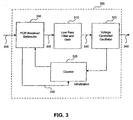
- FIG. 3 illustrates the conventional approach to encoder clock recovery.
- a circuit 300 comprises a PCR receiver/subtractor 310, a low-pass filter and gain unit 315, a voltage controlled oscillator 320, and a counter 325.
- the PCR receiver/subtractor 310 Upon receipt of a transport stream 305, the PCR receiver/subtractor 310 detects the PCR values embedded in the transport stream 305, compares the local time stamps from the counter 325 with those timestamps detected in the incoming transport stream 305. Based on this comparison, an error signal 335 is generated which is coupled to the low pass filter and gain unit 315.
- the output of the low pass filter and gain unit 315 is a correction signal 340 and is coupled to the voltage controlled oscillator 320.
- packet n In order to calculate the transport rate R( m ) at the encoder (during transmission), packet n must be selected, for which there are at least two approaches for making this selection.
- the first approach is to use the preceding packet that contains embedded transport rate information. In this case, the transport rate is computed by dividing the number of bits transmitted since the last packet containing transport rate information by the amount of time taken to send those bits.
- the second approach is to use the next packet containing transport rate information, in which case the transport rate is computed by dividing the number of bits transmitted until the next packet containing the transport rate information divided by the amount of time taken to send those bits. Either approach may be used provided both the encoders and decoders use the same approach.
- PES packets are not required. Under these circumstances, PTS and DTS values are not created.
- the relationship between the display time of the initial access unit (either audio, video or data) is always fixed with respect to all succeeding access units once the information coding structure is known at the elementary stream level.
- the only values needed in order to properly display and synchronize the digitized information sources are the initial display_time and one initial value for the system time clock (STC). Once these initial values are known, the display time for all subsequent access units can be derived. Therefore, in an embodiment of the current invention, in the scenario where PES packets are not used, the display_time and time_offset of the initial STC will be transferred.
Landscapes
- Engineering & Computer Science (AREA)
- Signal Processing (AREA)
- Multimedia (AREA)
- Computer Networks & Wireless Communication (AREA)
- Physics & Mathematics (AREA)
- Spectroscopy & Molecular Physics (AREA)
- Compression Or Coding Systems Of Tv Signals (AREA)
- Synchronisation In Digital Transmission Systems (AREA)
- Time-Division Multiplex Systems (AREA)
Abstract
Description
- The present application claims the benefit of
U.S. Provisional Patent Application No. 60/792,337, filed on Apr. 17, 2006 - The present invention relates to a clock recovery system, and more specifically to a clock recovery system for receiving MPEG-2 signals.
- The ISO Moving Picture Experts Group (MPEG) established a standard by which digital bit representations of audio, video and data sources can be encoded, transmitted, received, and reliably decoded. This standard has been published as document ITU-T H.222.0, entitled "Information Technology - Generic Coding of Moving Pictures and Associated Audio Information: Systems". The MPEG-2 standard enables the transmission of digitized audio and video data in packetized form for insertion into a transport stream. Multiple sources of data may be multiplexed so that many users may share the same communications path.
- In order to ensure reliable delivery of the audio, video and data to the end-user, the decoder clock must be synchronized with the encoder clock. Absence of synchronization will result in frame skips or frame holds in the case of video information, or its equivalent in the case of audio information. In order to achieve synchronization between the encoding clock and the decoding clock, the encoder inserts a time stamp into the transport stream, such a time stamp is known as a Program Clock Reference (PCR). The decoder uses these time stamps to ensure that the decoder time clock is synchronized to the encoder time clock and that the resulting transmission of audio, video and data is properly received and decoded.
- In the traditional system infrastructure, if there are no PCR values carried within the stream, the decoder cannot evaluate the transport rate, it cannot lock on to the information stream, and the decoder clock will not be synchronized with the encoder clock.
- What is needed is a more flexible approach to ensure the reliable decoding of single and multiplexed audio, video and data streams without the need to use PCR values. Further, it is desirable that the new approach require changes to firmware only and thereby be able to use existing PCR-based hardware.
- The present invention is directed to a clock recovery system without the need to embed PCR values into the information byte-stream. Instead, by occasionally transferring the transport rate and the packet count, synchronization of the decoder clock to the encoder clock can be achieved. This new approach requires changes to firmware only and therefore existing PCR-based hardware can be used.
- In an embodiment of this invention involving re-multiplexing, the values of the incoming transport rate and packet count are re-evaluated and updated for insertion into the output stream. According to an aspect of the invention, in a communications system, a clock recovery apparatus to recover an encoder clock for received packets is provided, comprising:
- a packet receiver configured to detect packet count information and transport rate information that is representative of the encoder clock for the received packets;
- a voltage controlled oscillator for generating a local system time clock, the voltage controlled oscillator having an input that allows the frequency of the system time clock to be adjusted in proportion to a control signal received on the input;
- a feedback loop adapted to output an error signal that represents the difference between the frequency of the local system time clock and the frequency of the representative encoder clock; and
- a low-pass filter circuit adapted to filter the error signal for input to the voltage controlled oscillator.
- Advantageously, the packet receiver includes a packet timing extractor for outputting timestamp data that is representative of the encoder clock based on the packet count information and the transport rate information; and
wherein the feedback loop further comprises a counter to output local timestamp data whose value increments with the system time clock cycles, the counter having an input that initializes its output value, and a jitter calculator to output the error signal equal to the difference between the timestamp data from the counter and the timestamp data from the receiver. - Advantageously, the packets received are MPEG-2 type packets.
- Advantageously, the frequency of the system time clock is in the range of 26.999199 MHz to 27.000810 MHz.
- Advantageously, the counter is a digital counter.
- Advantageously, the packet receiver retrieves the packet count information and the transport rate information from a header portion of one or more of said received packets.
- Advantageously, the received packets are MPEG packets, and the packet count information and transport data rate are located in an adaptation field of a header portion of the MPEG header.
- According to an aspect of the invention, a method for reconstructing a system clock is provided, comprising:
- receiving digitized packets containing packet count information and transport rate information from a sending clock;
- determining timestamps from the packet count information and the transport rate information;
- generating a local system clock based on a control signal, and generating local timestamps based on the local system clock;
- generating an error signal based on the difference between the local timestamps and the timestamps determined from the received packet count information and transport rate information; and
- filtering the error signal to produce the control signal.
- Advantageously, the digitized packets are MPEG-2 packets.
- Advantageously, the step of determining timestamps from the packet count information and the transport rate information includes the steps of retrieving the packet count information and the transport rate information from a header of the MPEG-2 packet.
- Advantageously, the step of retrieving includes the step of retrieving the packet count information and the transport rate information from the adaptation field of the header of the MPEG-2 packet.
- According to an aspect of the invention, a method is provided for encoding a plurality of data packets with timestamp information for transmission over a communications system, comprising:
- receiving a plurality of data packets;
- determining packet count information and transport rate information for the plurality of data packets; and
- loading the packet count information and transport rate information in header portions of one or more of the plurality of data packets.
- Advantageously, the data packets are MPEG-2 data packets, and wherein the step of loading includes the step of inserting packet count information and transport rate information in an adaptation field of the header portions of the data packets.
- Advantageously, the packet count information and the transport rate information represent the timestamp information.
- Further embodiments, features, and advantages of the present invention, as well as the structure and operation of the various embodiments of the present invention are described in detail below with reference to accompanying drawings.
- The present invention is described with reference to the accompanying drawings. In the drawings, like reference numbers indicate identical or functionally similar elements. The drawing in which an element first appears is indicated by the left-most digit in the corresponding reference number.
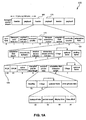
- FIG. 1A is a diagram of the structure of a MPEG-2 packet.
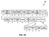
- FIG. 1B is a diagram of the structure of a Program Map Table (PMT).
- FIG. 2 is a diagram of the structure of a PES packet.
- FIG. 3 is a block diagram of a conventional circuit for system clock recovery using PCR values.
- FIG. 4 is a block diagram of a system clock recovery circuit without using PCR values, according to an embodiment of the invention.
- FIG. 5 is a block diagram of a conventional system for re-multiplexing using PCR values.
- FIG. 6 is a block diagram of a re-multiplexing system without using PCR values, according to an embodiment of the invention.
- FIG. 7 is a flowchart diagram that illustrates a method of generating data packets having packet count and rate information without directly sending PCR timestamps, according to embodiment of the present invention.
- FIG. 8 is a flowchart diagram that illustrates a method for recovering a system clock, according to an embodiment of the invention.
- FIG. 9 is a flowchart diagram that illustrates a method for re-multiplexing a plurality of transport streams, according to an embodiment of the invention.
- While the present invention is described herein with reference to illustrative embodiments for particular applications, it should be understood that the invention is not limited thereto. Those skilled in the art with access to the teachings provided herein will recognize additional modifications, applications, and embodiments within the scope thereof and additional fields in which the present invention would be of significant utility.
- MPEG-2 provides for the packetized transport of digitized video, audio, and data sources. Such packets are of a fixed 188-byte size, and include a
header 105 and apayload 110. FIG. 1A indicates the structure of an MPEG-2packet 100. Theheader 105 includes a 13-bit program ID (PID)field 115, which serves to identify the information in the packet as belonging to a particular stream of information. The MPEG-2 packet also includes anadaptation field 120, which includes of a series of flags, together with optional fields whose presence is indicated by the value of the preceding flags. Private user data can be defined and carried within theadaptation field 120. Inconventional MPEG 115, PCR values 125 are embedded within a MPEG-2 transport stream and provide the traditional method for recovery of an encoder clock in the decoder system. - FIG. 1B is a diagram of the structure of a Program Map Table (PMT) 130. A
PMT 130 serves to identify the video, audio, and data content of a particular transport stream. In a typical example, aPMT 130 would identify thePID 135 for the audio component of a particular program, as well as theseparate PIDs 135 for any video or data component of the particular program. - Prior to being packetized into the fixed-length MPEG-2 packets, video, audio, and data sources are initially packetized into Packetized Elementary Streams (PES). FIG. 2 indicates the structure of a
PES packet 200. The following fields are optionally embedded within a PES packet: (a) decoding time stamp (DTS) 205, which indicates the time at which a packet is to be decoded by the decoder; and (b) presentation time stamp (PTS) 210 that signals the decoder system as to the timing of presentation of the individual units of video and audio information. In order to ensure synchronization, the PTS values 205 and the DTS values 210 are derived from the same clock that provides the PCR values. - FIG. 3 illustrates the conventional approach to encoder clock recovery. Such a
circuit 300 comprises a PCR receiver/subtractor 310, a low-pass filter and gainunit 315, a voltage controlledoscillator 320, and acounter 325. Upon receipt of atransport stream 305, the PCR receiver/subtractor 310 detects the PCR values embedded in thetransport stream 305, compares the local time stamps from thecounter 325 with those timestamps detected in theincoming transport stream 305. Based on this comparison, anerror signal 335 is generated which is coupled to the low pass filter and gainunit 315. The output of the low pass filter and gainunit 315 is acorrection signal 340 and is coupled to the voltage controlledoscillator 320. The output of the voltage controlledoscillator 320 is coupled to thecounter 325 as part of the feedback loop. If the PCR value detected by the PCR receiver/subtractor 310 is an initial value, the PCR receiver/subtractor 310 generates aninitialization signal 330, which initializes thecounter 325. As noted above, in order for theconventional circuit 300 to function correctly, PCR values must be embedded into thetransport stream 305. - Using the conventional approach of FIG. 3, the transport rate is derived at the decoder side by using the PCR values, as follows:

- i
- is the index of any byte in the transport stream for i"<i <i'.
- i'
- is the index of the byte containing the last bit of the immediately following program_clock reference_base field applicable to the program being decoded.
- i"
- is the index of the byte containing the last bit of the most recent program_clock_reference_base field applicable to the program being decoded.
- PCR(i")
- is the time encoded in the program clock reference base and extension fields in units of the system clock.
- If the transport rate is assumed to be constant, any deviation in the sequence of PCR values can be interpreted as PCR jitter. To lock onto the
incoming transport stream 305, the conventional decoder has to evaluate each PCR value and adjust its local phase-locked loop (PLL) to absorb the resulting jitter. - As an alternative to embedding PCR values into the
transport stream 305 and the associated requirement of evaluating each PCR value, the current invention occasionally transfers the transport rate explicitly such that the decoder can use this explicit transport rate as a locking reference with which to adjust its clock. The transport rate value is embedded as user private data in theadaptation field 120 of the MPEG-2 packet. For each occasional MPEG-2 packet m carrying such user private data, the transport rate R(m) at the encoder is calculated as follows:

- R(m)
- : transport rate carried in packet m
- b
- : total number of bits transferred between packet number m and packet number n
- m
- : packet number carrying R(m)
- n
- : packet number carrying R(n)
- packet_length
- : length in bytes of each transport packet
- SC
- : system clock measured in Hz. 27,000,000 - 801 ≤ SC ≤ 27,000,000 + 810
- Δt(m,n)
- : encoder sampling time difference between packet m and packet n, in units of one tick of a 27 MHz clock.
- In order to calculate the transport rate R(m) at the encoder (during transmission), packet n must be selected, for which there are at least two approaches for making this selection. The first approach is to use the preceding packet that contains embedded transport rate information. In this case, the transport rate is computed by dividing the number of bits transmitted since the last packet containing transport rate information by the amount of time taken to send those bits. The second approach is to use the next packet containing transport rate information, in which case the transport rate is computed by dividing the number of bits transmitted until the next packet containing the transport rate information divided by the amount of time taken to send those bits. Either approach may be used provided both the encoders and decoders use the same approach.
- At the decoder side, the local system time counter is used to estimate the transport rate R'(m). The difference between the actual encoder transport rate, R(m), and the transport rate R'(m) estimated by the decoder, together with the total number of intervening bits b, creates an error signal by which the decoder can lock or synchronize its time clock to that of the encoder. As noted below, one possible decoder design objective in a particular embodiment of the invention would be to keep the decoder clock synchronized with the encoder system time clock to better than one-half a microsecond. Different embodiments of the design for different applications may choose different synchronization design objectives.

- R'(m)
- : Calculated transport rate based on local time
- Δt'(m, n)
- : Sampling time difference based on decoder's local counter
- As the equation above indicates, the accuracy of the estimated transport rate R'(m) depends on the packet numbers n and m. If during the transmission, packets are either dropped or added, as would be the case during re-multiplexing, the sampling time distance will change with the result that the encoder and the decoder can no longer synchronize. To address this issue, packet numbers n and m are explicitly embedded in the transport stream, as well as the transport rate information. For example, the encoder explicitly sends packet number m in the same packet that carries the transport rate R(m).
- The table below illustrates the relationship between the PCR_jitter of the conventional PCR_based approach of system clock recovery and the embedded transport rate information R(m) approach of this invention. Consider a transport stream with theoretical transport rate of 12.5 Mbps. The PCR values are carried as follows:
Packet PCR_value PCR_jitter (ns) R'(m) (bps) 113 14695 430 1044514 -4.421 12499998.54 747 2074333 -4.421 12499998.54 1064 3104152 -4.421 12499998.54 1381 4133971 -4.421 12499998.54 1698 5163790 -4.421 12499998.54 2015 6193608 32.616 12500010.68 2332 7223427 -4.421 12499998.54 - FIG. 4 illustrates the block diagram of a decoder
clock recovery circuit 400, according to an embodiment of the invention. This circuit includes: apacket receiver 406 having atransport buffer 407 and atiming information extractor 410; ajitter calculator 415, a low-pass filter 420, a voltage controlledoscillator 425, and acounter 430.Incoming packet streams 405 are received by thetransport buffer 407, which is coupled to thetiming information extractor 410. Thetiming information extractor 410 is coupled to thejitter calculator 415 and the initialization port of thecounter 430. The output of thejitter calculator 415 is coupled to the low-pass filter 420. The output of the low-pass filter 420 is coupled to the voltage controlledoscillator 425. The output of the voltage controlledoscillator 425 provides the decodersystem clock output 455. The output of the voltage controlledoscillator 425 is also coupled to thecounter 430. Thecounter 430 is coupled to thejitter calculator 415. As noted earlier, this new approach requires changes to firmware only and therefore existing PCR-based hardware can be used. - The
packet receiver 406 receivesMPEG packets 405 and extracts timestampinformation 440 based on embedded transport rate information and packet count information. Specifically, thetransport buffer 407 captures the packets in the transport stream and distributes the relevant bytes to thetiming information extractor 410. Thetiming information extractor 410 detects the embedded transport rate information as well as the packet count information, and determines theencoder timestamp information 440 associated with the packets received. As discussed above, the packet transfer rate value can be embedded as user private data in theadaptation field 120 of the MPEG-2 packet. The packet count can also be embedded as user private data of theadaptation field 120 of the MPEG-2 packet. - The
encoder timestamp information 440 is forwarded to thejitter calculator 415 which generates anerror signal 445 based on the difference between theencoder timestamp 440 and the local timestamp obtained from thecounter 430. For thecounter 430 to have an accurate reading, thetiming information extractor 410 initiates thecounter 430 upon receipt of an initialization data string within the receiveddata stream 405. Theerror signal 445 generated by thejitter calculator 415 is passed through a low pass filter to create acorrection signal 450. Thecorrection signal 450 is input to the voltage controlledoscillator 425 such that the frequency of the voltage controlledoscillator 425 is adjusted until it is synchronized to the encoder clock frequency. A sample of this output of the voltage controlledoscillator 425 is fed into thecounter 430. Thecounter 430 andjitter calculator 415 can be referred to as afeedback loop 414 because timestamps based on theVCO output 455 are compared to theencoder timestamp information 440 that is extracted from the received packets so as to create theerror signal 445. Theerror signal 445 is used to adjust the frequency of theVCO 425. - As noted above, the display_time, time_offset, transport_rate and packet_count are extracted by the
timing information extractor 410. During the initialization stage, display_time and time_offset are sent to thelocal counter 430. Transport_rate and packet_count are sent to the jitter calculator and are buffered together with the current system clock value. The jitter orerror signal 445 is calculated based on the following items: previous_packet_count, previous_system_clock_value, current_packet_count, current_system_clock_value, and current_transport_rate. The resulting jitter orerror signal 445 is low-pass filtered and used as control to the VCO to recover the system clock. An example formula to calculate theerror signal 445, shown as e below, is provided as follows: -

- All data that are necessary to recover the system time clock in this invention are carried in the adaptation field as user private data. In circumstances where one MPEG-2 program contains both audio and video information, an embodiment of the current invention offers an efficiency in terms of clock recovery effort. Rather than having each individual audio and video information stream of a particular program carry its own clock recovery data, this redundancy can be avoided by placing a Time Recovery Descriptor into the first descriptor loop of the particular program's map table (PMT). The syntax and semantic definition of such a Time Recovery Descriptor is shown below:
Syntax Semantic Definition Descriptor_tag 8-bit field set to 0xFF. Descriptor_ length 8-bit field specifying the number of descriptor bytes immediately following the descriptor length. Identifier 32-bit field that identifies the Time Recovery Descriptor. This value should be 0x4252434D. Reserved 3-bit reserved field that should be '111'. Time_Recovery_PID 13-bit field specifying which PID is used to recover the system time clock. - As noted above, all data necessary to recover the system time clock in this invention is carried in adaptation field's user private data. The syntax and semantic definition of the Program Time Recovery Private Field is shown below. It should be noted that when the random_access_indicator is set to 1, the user_private_data_flag must also be set to 1.
Syntax Semantic Definition if (transport_private_data_flag=='1') { transport_private_data_length 8-bit field specifying the number of private data bytes immediately following the transport_private_data_length. Identifier 32-bit field that identifies the time recovery private field. The value should be set to 0x4252434D. Reserved 4-bit reserved field that should be'1111'. transport_rate_flag 1-bit flag. When it equals '1', transport_rate is carried in the following syntax. Packet_count_flag 1-bit flag. When it equals to '1', packet_count is carried in the following syntax. Display_time_flag 1-bit flag. When it equals to '1', display_time is carried in the following syntax. time_offset_flag 1-bit flag. When it equals to '1', time_offset is carried in the following syntax. if (transport_rate_flag) transport_rate 32-bit field carrying the transport rate as determined by the encoder. The unit of transport_rate is bits per second. if (packet_count_flag) Packet_count 32-bit field carrying the total output transport stream packet number modulo 2^32. if (display_time_flag) display_time 32-bit field carrying the display_time of the first access unit after the current adaptation_field. The unit of display_time is one tick per 90 kHz clock. If (time_offset_flag) time_offset 24-bit field carrying STC initialization offset relative to display_time carried in the same Time Recovery Private Field. } - Normally, the time delay between each random access unit is dependent upon the infrastructure, and can be as large as one to five seconds. However, to successfully guarantee the system clock update process, transport_rate and packet_count information have to be sent at least every 100 milliseconds. Accordingly, even in the absence of a random access unit, a time_recovery_private field must be carried to guarantee the integrity of the system clock update process. Therefore, a time_recovery_private field may be present even when the random_access_indicator flag is set to zero.
- In certain infrastructures, PES packets are not required. Under these circumstances, PTS and DTS values are not created. However, the relationship between the display time of the initial access unit (either audio, video or data) is always fixed with respect to all succeeding access units once the information coding structure is known at the elementary stream level. Thus, the only values needed in order to properly display and synchronize the digitized information sources are the initial display_time and one initial value for the system time clock (STC). Once these initial values are known, the display time for all subsequent access units can be derived. Therefore, in an embodiment of the current invention, in the scenario where PES packets are not used, the display_time and time_offset of the initial STC will be transferred.
- If the infrastructure does not use packetized elementary stream (PES) packet wrapping, all PIDs shall carry the time_recovery_private field containing display_time in order to synchronize to each other. However, only one PID is required to carry the transport_rate, packet_count and time_offset to initialize the system time clock (STC).
- Through multiplexing, MPEG-2 permits multiple types of multimedia information to be combined into one single byte stream. A common circumstance is where a service provider will accept multiple transport streams from various sources and thereby create its own transport stream by selecting different programs from different sources. This combination requires the use of a re-multiplexer. FIG. 5 shows a conventional transport stream
re-multiplexing engine 500. Two transport stream inputs,input_stream_1 505 andinput_stream_2 510, each carrying embedded PCR values, are sent to the re-multiplexing engine. The re-multiplexing engine in turn generates a single combinedoutput_stream 515. Within the re-multiplexing engine, the output packet is selected either frominput_stream_1 505 or frominput_stream_2 510. The packet routing and dropping selection is based on the output transport rate and the scheduling algorithm of the re-multiplexing engine. If the scheduling algorithm guarantees performance, there is no need to adjust PCR values in the output transport stream. Therefore, the PCR values can remain the same as they were ininput_stream_1 505 andinput_stream_2 510. - In the present invention, PCR values are not carried within the input transport streams. On the other hand, transport rate information and packet count information are carried occasionally. Thus at the re-multiplexing stage, the values of transport rate and packet count need to be re-evaluated and updated in the output stream.
- FIG. 6 shows a re-multiplexing engine, according to an embodiment of the invention. Two transport stream inputs, input_stream _1 605 and
input_stream_2 610, each occasionally carrying embedded transport rate information and embedded packet count information, are sent to the re-multiplexing engine. The re-multiplexing engine in turn generates a single combinedoutput_stream 615. Within the re-multiplexing engine, the output packet is selected either frominput_stream_1 605 or frominput_stream_2 610. During the re-multiplexing, the transport rate information and the packet count information are re-evaluated, updated and re-inserted into theoutput transport stream 615. - Error handling in an embodiment of this invention is handled as follows. For the situation of a marked time_base discontinuity, the following approach is taken: If the discontinuity indicator is set, LSCS1 = display_time - time_offset is calculated and loaded into STC base immediately. For the situation of an unmarked time_base discontinuity, the following approach is taken: |LSTC - (display_time - time_offset)|> THR, where THR is a settable threshold. In this case, LSCS1 = display_time - time_offset is calculated and loaded into STC base immediately.
- FIG. 7 illustrates a
flowchart 700 that further describes encoding digital communication packets for transmission over a communications system. The digital communications packets are encoded with packet count information and packet transport rate information. Based on the invention described herein, it is no longer required to send PCR information in the data stream. The stream may contain no PCR information, although it is still allowed. Instead, the transport rate is used to represent the jitter. Transport rate represents a period and PCR is an instantaneous value. Using transport rate and packet count (which is sent is case of packet loss), a timing duration is derived between two packets containing the timing information. To calculate the timestamp, the previous system clock value is added to this timing duration. For example, the equation in paragraph 0037 provides the details for this calculation. - In
step 702, a plurality of data packets are received, such as MPEG-2 data packets. - In
step 704, packet count information and transport rate information for the data packets is determined. - In
step 706, the packet count information and the transport rate information is loaded into data packets prior to transmission. For instance, the packet count information and data transport information could be loaded into the header of the data packets during data packet encoding at the transmitter. More specifically, for MPEG-2, the packet count information and data transport information can be loaded into theadaptation field 120 of the MPEG-2header 105 that is illustrated in FIG. 1A. - In
step 708, the data packets are transmitted over a communications network for receipt and processing. - FIG. 8 illustrates a
flowchart 800 for reconstructing a system clock based on data packets carrying packet count and transport rate information. The invention described herein is not limited by the order of the steps in theflowchart 800. In other words, some of the steps can be performed simultaneously, or in a different order, without deviating from the scope and spirit of the invention. - In
step 802, packets containing packet count information and transport rate information from an encoding clock are received. - In
step 804, the packet count information and transport rate information is retrieved from the received data packets. For example, thetiming information extractor 410 can extract the packet count information and the transport rate information from MPEG packets. In one embodiment, theadaptation field 120 in an MPEG stream of packets carries the packet count information and the transport data rate information. - At
step 806, timestamps are determined from the packet count information, the transport rate information, and previous local system clock value. - At a
step 808, a local system clock is generated based on a control signal. For example, theVCO 425 generates a local system clock based on acontrol signal 450. Step 808 also includes the steps of generating local time stamps from the local system clock. - At a
step 810, an error signal is generated that is based on the difference between the timestamps computed from the received packet count information and received transport rate information, and timestamps determined from the local system time clock. For example, thejitter calculator 415 generates an error control signal. - At a
step 812, the error signal is filtered to produce the control signal. For example, thelow pass filter 420 generates a filtered output of theerror signal 445, so as to generate thecontrol signal 450. - FIG. 9 illustrates 900 that describes the operational steps for a re-multiplexing system, such as
re-multiplexing system 500. At astep 905, a plurality of transport streams of information packets containing packet count information and transport rate information are received. At astep 910, the packet count information and the transport rate information are updated. At astep 915, the updated packet count information and transport rate information is inserted into the combined output transport stream of transmitted information packets. - Finally, it should be noted that the invention described herein is not limited to MPEG-2 clock recovery applications. For example, the nominal frequency of the system time clock can be any frequency; the MPEG-2 frequency of 27 MHz is merely an example. Similarly, the use of embedded transport rate information and packet count information for clock recovery purposes is not limited to MPEG-2 packet structures, but is equally applicable to any transport streams for which clock recovery is required at the destination. More specifically, the invention is applicable to other packet based communications system, other than MPEG.
- While various embodiments of the present invention have been described above, it should be understood that they have been presented by way of example, and not limitation. It will be apparent to persons skilled in the relevant art that various changes in form and detail can be made therein without departing from the spirit and scope of the invention.

Claims (10)
- In a communications system, a clock recovery apparatus to recover an encoder clock for received packets, comprising:a packet receiver configured to detect packet count information and transport rate information that is representative of the encoder clock for the received packets;a voltage controlled oscillator for generating a local system time clock, the voltage controlled oscillator having an input that allows the frequency of the system time clock to be adjusted in proportion to a control signal received on the input;a feedback loop adapted to output an error signal that represents the difference between the frequency of the local system time clock and the frequency of the representative encoder clock; anda low-pass filter circuit adapted to filter the error signal for input to the voltage controlled oscillator.
- The clock recovery apparatus of claim 1,
wherein the packet receiver includes a packet timing extractor for outputting timestamp data that is representative of the encoder clock based on the packet count information and the transport rate information; and
wherein the feedback loop further comprises a counter to output local timestamp data whose value increments with the system time clock cycles, the counter having an input that initializes its output value, and a jitter calculator to output the error signal equal to the difference between the timestamp data from the counter and the timestamp data from the receiver. - The clock recovery apparatus of claim 1, wherein the packets received are MPEG-2 type packets.
- The clock recovery apparatus of claim 1, wherein the frequency of the system time clock is in the range of 26.999199 MHz to 27.000810 MHz.
- The clock recovery apparatus of claim 1, wherein the packet receiver retrieves the packet count information and the transport rate information from a header portion of one or more of said received packets.
- A method for reconstructing a system clock, comprising:receiving digitized packets containing packet count information and transport rate information from a sending clock;determining timestamps from the packet count information and the transport rate information;generating a local system clock based on a control signal, and generating local timestamps based on the local system clock;generating an error signal based on the difference between the local timestamps and the timestamps determined from the received packet count information and transport rate information; andfiltering the error signal to produce the control signal.
- The method of claim 6, wherein the digitized packets are MPEG-2 packets.
- The method of claim 7, wherein the step of determining timestamps from the packet count information and the transport rate information includes the steps of retrieving the packet count information and the transport rate information from a header of the MPEG-2 packet.
- A method for encoding a plurality of data packets with timestamp information for transmission over a communications system, comprising:receiving a plurality of data packets;determining packet count information and transport rate information for the plurality of data packets; andloading the packet count information and transport rate information in header portions of one or more of the plurality of data packets.
- The method of claim 9, wherein the data packets are MPEG-2 data packets, and wherein the step of loading includes the step of inserting packet count information and transport rate information in an adaptation field of the header portions of the data packets.
Applications Claiming Priority (2)
| Application Number | Priority Date | Filing Date | Title |
|---|---|---|---|
| US79233706P | 2006-04-17 | 2006-04-17 | |
| US11/529,607 US9544638B2 (en) | 2006-04-17 | 2006-09-29 | Method for reconstructing system time clock (STC) without carrying PCR |
Publications (3)
| Publication Number | Publication Date |
|---|---|
| EP1848221A2 true EP1848221A2 (en) | 2007-10-24 |
| EP1848221A3 EP1848221A3 (en) | 2008-04-16 |
| EP1848221B1 EP1848221B1 (en) | 2015-09-09 |
Family
ID=38370950
Family Applications (1)
| Application Number | Title | Priority Date | Filing Date |
|---|---|---|---|
| EP06024397.9A Ceased EP1848221B1 (en) | 2006-04-17 | 2006-11-24 | Method for reconstructing system time clock (STC) without carrying PCR |
Country Status (4)
| Country | Link |
|---|---|
| US (1) | US9544638B2 (en) |
| EP (1) | EP1848221B1 (en) |
| CN (1) | CN101102496B (en) |
| TW (1) | TWI455573B (en) |
Cited By (1)
| Publication number | Priority date | Publication date | Assignee | Title |
|---|---|---|---|---|
| EP3089471A4 (en) * | 2013-12-25 | 2016-12-14 | Le Holdings Beijing Co Ltd | METHOD AND DEVICE FOR VIDEO LAUNDRY |
Families Citing this family (12)
| Publication number | Priority date | Publication date | Assignee | Title |
|---|---|---|---|---|
| AU2002220286A1 (en) * | 2000-12-19 | 2002-07-01 | Azoteq (Pty) Ltd. | Method of and apparatus for transferring data |
| JP4762052B2 (en) * | 2006-05-31 | 2011-08-31 | パナソニック株式会社 | Stream data processing apparatus and stream data processing method |
| US8363764B2 (en) * | 2007-08-06 | 2013-01-29 | Lantiq Deutschland Gmbh | Method and device for reconstructing a data clock from asynchronously transmitted data packets |
| US20110096845A1 (en) * | 2009-10-22 | 2011-04-28 | Rajesh Mamidwar | Method and system for providing decoupled streams for clock recovery and decoding |
| CN101867803B (en) * | 2010-05-21 | 2012-11-28 | 杭州华三通信技术有限公司 | Data transmission method, equipment and system |
| DE102012206910A1 (en) * | 2011-12-06 | 2013-06-06 | Rohde & Schwarz Gmbh & Co. Kg | Method and device for signaling a transmission time and / or a system clock |
| US8832338B2 (en) | 2013-01-08 | 2014-09-09 | Silicon Image, Inc. | Mechanism for facilitating dynamic timestamp-less clock generation for transmitting media streams over shared channels |
| JP6232870B2 (en) * | 2013-09-11 | 2017-11-22 | 株式会社リコー | Wireless communication system, wireless communication method, program, and recording medium |
| US10547884B2 (en) * | 2014-06-24 | 2020-01-28 | Samsung Electronics Co., Ltd. | Technique for transmitting and receiving system time information in broadcasting system |
| CN111095887B (en) * | 2017-09-29 | 2025-06-20 | 英特尔公司 | Phase-locked loop switching in communication systems |
| CN111522703B (en) * | 2019-02-01 | 2023-08-11 | 伊姆西Ip控股有限责任公司 | Method, apparatus and computer program product for monitoring access requests |
| CN112448715B (en) * | 2019-08-28 | 2023-12-08 | 珠海格力电器股份有限公司 | Method and system for calibrating HIRC by using PES (PES) signal |
Citations (1)
| Publication number | Priority date | Publication date | Assignee | Title |
|---|---|---|---|---|
| CA2184517A1 (en) | 1996-08-30 | 1998-03-01 | Randy A. Law | Clock recovery for video communication over atm network |
Family Cites Families (20)
| Publication number | Priority date | Publication date | Assignee | Title |
|---|---|---|---|---|
| US5612981A (en) | 1994-02-15 | 1997-03-18 | Philips Electronics North America Corporation | Apparatus and methods for improving timing recovery of a system clock |
| US6233256B1 (en) | 1996-03-13 | 2001-05-15 | Sarnoff Corporation | Method and apparatus for analyzing and monitoring packet streams |
| US6496543B1 (en) * | 1996-10-29 | 2002-12-17 | Qualcomm Incorporated | Method and apparatus for providing high speed data communications in a cellular environment |
| US6157659A (en) * | 1997-12-19 | 2000-12-05 | Nortel Networks Corporation | Method of and apparatus for multiplexing and demultiplexing digital signal streams |
| AU5763698A (en) * | 1997-12-23 | 1999-07-19 | Nokia Telecommunications Oy | Clock generating method and apparatus for an asynchronous transmission |
| FI105974B (en) * | 1998-06-22 | 2000-10-31 | Nokia Mobile Phones Ltd | Method for encoding a signal in a data transmission system and data transmission system |
| US6195392B1 (en) * | 1998-06-30 | 2001-02-27 | U.S. Philips Corporation | Method and arrangement for generating program clock reference values (PCRS) in MPEG bitstreams |
| JP4193297B2 (en) * | 1999-08-04 | 2008-12-10 | ソニー株式会社 | COMMUNICATION DEVICE AND METHOD, COMMUNICATION SYSTEM, AND RECORDING MEDIUM |
| US6721328B1 (en) * | 1999-11-19 | 2004-04-13 | Adc Telecommunications, Inc. | Adaptive clock recovery for circuit emulation service |
| US7106758B2 (en) * | 2001-08-03 | 2006-09-12 | Adc Telecommunications, Inc. | Circuit and method for service clock recovery |
| CN1314269C (en) * | 2002-04-02 | 2007-05-02 | 中兴通讯股份有限公司 | Method and device for regulating program reference clock of motion image expert group 2 |
| JP4649210B2 (en) * | 2002-12-16 | 2011-03-09 | コーニンクレッカ フィリップス エレクトロニクス エヌ ヴィ | System for correcting the time axis of video signals |
| US7103072B1 (en) * | 2002-12-19 | 2006-09-05 | Occam Networks | System and method for synchronization of devices across a packet network |
| US7539209B2 (en) * | 2003-03-05 | 2009-05-26 | Ciena Corporation | Method and device for preserving pacing information across a transport medium |
| US7397825B2 (en) * | 2004-03-10 | 2008-07-08 | Scientific-Atlanta, Inc. | Transport stream dejitterer |
| JP4096915B2 (en) * | 2004-06-01 | 2008-06-04 | 株式会社日立製作所 | Digital information reproducing apparatus and method |
| CN1722776A (en) * | 2004-07-16 | 2006-01-18 | 上海乐金广电电子有限公司 | Clock restoring arrangement in digital broadcasting receiver |
| US7176928B1 (en) * | 2004-12-13 | 2007-02-13 | Network Equipment Technologies, Inc. | Recovery of a serial bitstream clock at a receiver in serial-over-packet transport |
| US7693244B2 (en) * | 2006-03-31 | 2010-04-06 | Intel Corporation | Encoding, clock recovery, and data bit sampling system, apparatus, and method |
| US7924885B2 (en) * | 2006-11-20 | 2011-04-12 | Siverge Networks Ltd | Methods and apparatuses for circuit emulation multi-channel clock recovery |
-
2006
- 2006-09-29 US US11/529,607 patent/US9544638B2/en not_active Expired - Fee Related
- 2006-11-24 EP EP06024397.9A patent/EP1848221B1/en not_active Ceased
-
2007
- 2007-04-11 TW TW096112672A patent/TWI455573B/en not_active IP Right Cessation
- 2007-04-12 CN CN2007100971903A patent/CN101102496B/en not_active Expired - Fee Related
Patent Citations (1)
| Publication number | Priority date | Publication date | Assignee | Title |
|---|---|---|---|---|
| CA2184517A1 (en) | 1996-08-30 | 1998-03-01 | Randy A. Law | Clock recovery for video communication over atm network |
Cited By (1)
| Publication number | Priority date | Publication date | Assignee | Title |
|---|---|---|---|---|
| EP3089471A4 (en) * | 2013-12-25 | 2016-12-14 | Le Holdings Beijing Co Ltd | METHOD AND DEVICE FOR VIDEO LAUNDRY |
Also Published As
| Publication number | Publication date |
|---|---|
| US20070242678A1 (en) | 2007-10-18 |
| EP1848221B1 (en) | 2015-09-09 |
| TW200820793A (en) | 2008-05-01 |
| US9544638B2 (en) | 2017-01-10 |
| EP1848221A3 (en) | 2008-04-16 |
| CN101102496B (en) | 2010-11-10 |
| CN101102496A (en) | 2008-01-09 |
| TWI455573B (en) | 2014-10-01 |
Similar Documents
| Publication | Publication Date | Title |
|---|---|---|
| TWI455573B (en) | Method for reconstructing system time clock (stc) without carrying pcr | |
| US8351514B2 (en) | Method, protocol, and apparatus for transporting advanced video coding content | |
| JP4979039B2 (en) | How to send compressed video data | |
| EP3131301B1 (en) | Transmission apparatus, transmission method, reception apparatus and reception method | |
| JP2001358685A (en) | Synchronizing device and synchronizing method | |
| JP2012513139A (en) | Method for synchronizing transport streams in a multiplexer with an external coprocessor | |
| EP0933949B1 (en) | Transmitting system, transmitting apparatus, recording and reproducing apparatus | |
| WO2008151989A2 (en) | System and method for transport of a constant bit rate stream | |
| CN102204249B (en) | Constant bit rate padding of mpeg transport streams | |
| US6266384B1 (en) | Method and apparatus for time base recovery and processing | |
| KR100390138B1 (en) | A method for transmitting isochronous data, a method and apparatus for restoring isochronous data, a decoder for restoring information data | |
| EP1836786B1 (en) | Method of transmitting mpeg streams over ip and corresponding device, receiving method and receiver | |
| KR100211999B1 (en) | Pcr corrector of mpeg-2 transport stream remultiplexer | |
| JP3090129B2 (en) | Multiplexer | |
| JP2000134259A (en) | Transmission method and transmission device | |
| KR0138123B1 (en) | An apparatus for coding time-stamp in mpeg-2 system |
Legal Events
| Date | Code | Title | Description |
|---|---|---|---|
| PUAI | Public reference made under article 153(3) epc to a published international application that has entered the european phase |
Free format text: ORIGINAL CODE: 0009012 |
|
| AK | Designated contracting states |
Kind code of ref document: A2 Designated state(s): AT BE BG CH CY CZ DE DK EE ES FI FR GB GR HU IE IS IT LI LT LU LV MC NL PL PT RO SE SI SK TR |
|
| AX | Request for extension of the european patent |
Extension state: AL BA HR MK YU |
|
| PUAL | Search report despatched |
Free format text: ORIGINAL CODE: 0009013 |
|
| AK | Designated contracting states |
Kind code of ref document: A3 Designated state(s): AT BE BG CH CY CZ DE DK EE ES FI FR GB GR HU IE IS IT LI LT LU LV MC NL PL PT RO SE SI SK TR |
|
| AX | Request for extension of the european patent |
Extension state: AL BA HR MK RS |
|
| 17P | Request for examination filed |
Effective date: 20081016 |
|
| 17Q | First examination report despatched |
Effective date: 20081117 |
|
| AKX | Designation fees paid |
Designated state(s): DE FR GB |
|
| REG | Reference to a national code |
Ref country code: DE Ref legal event code: R079 Ref document number: 602006046556 Country of ref document: DE Free format text: PREVIOUS MAIN CLASS: H04N0007620000 Ipc: H04N0021235000 |
|
| RIC1 | Information provided on ipc code assigned before grant |
Ipc: H04N 21/235 20110101AFI20150216BHEP |
|
| GRAP | Despatch of communication of intention to grant a patent |
Free format text: ORIGINAL CODE: EPIDOSNIGR1 |
|
| INTG | Intention to grant announced |
Effective date: 20150402 |
|
| GRAS | Grant fee paid |
Free format text: ORIGINAL CODE: EPIDOSNIGR3 |
|
| GRAA | (expected) grant |
Free format text: ORIGINAL CODE: 0009210 |
|
| AK | Designated contracting states |
Kind code of ref document: B1 Designated state(s): DE FR GB |
|
| REG | Reference to a national code |
Ref country code: GB Ref legal event code: FG4D |
|
| REG | Reference to a national code |
Ref country code: DE Ref legal event code: R096 Ref document number: 602006046556 Country of ref document: DE |
|
| REG | Reference to a national code |
Ref country code: FR Ref legal event code: PLFP Year of fee payment: 10 |
|
| REG | Reference to a national code |
Ref country code: DE Ref legal event code: R097 Ref document number: 602006046556 Country of ref document: DE |
|
| PLBE | No opposition filed within time limit |
Free format text: ORIGINAL CODE: 0009261 |
|
| STAA | Information on the status of an ep patent application or granted ep patent |
Free format text: STATUS: NO OPPOSITION FILED WITHIN TIME LIMIT |
|
| 26N | No opposition filed |
Effective date: 20160610 |
|
| REG | Reference to a national code |
Ref country code: FR Ref legal event code: PLFP Year of fee payment: 11 |
|
| REG | Reference to a national code |
Ref country code: DE Ref legal event code: R082 Ref document number: 602006046556 Country of ref document: DE Representative=s name: BOSCH JEHLE PATENTANWALTSGESELLSCHAFT MBH, DE Ref country code: DE Ref legal event code: R081 Ref document number: 602006046556 Country of ref document: DE Owner name: AVAGO TECHNOLOGIES INTERNATIONAL SALES PTE. LT, SG Free format text: FORMER OWNER: BROADCOM CORP., IRVINE, CALIF., US Ref country code: DE Ref legal event code: R081 Ref document number: 602006046556 Country of ref document: DE Owner name: AVAGO TECHNOLOGIES GENERAL IP (SINGAPORE) PTE., SG Free format text: FORMER OWNER: BROADCOM CORP., IRVINE, CALIF., US |
|
| REG | Reference to a national code |
Ref country code: GB Ref legal event code: 732E Free format text: REGISTERED BETWEEN 20171005 AND 20171011 |
|
| REG | Reference to a national code |
Ref country code: FR Ref legal event code: PLFP Year of fee payment: 12 |
|
| REG | Reference to a national code |
Ref country code: FR Ref legal event code: TP Owner name: AVAGO TECHNOLOGIES GENERAL IP PTE. LTD., SG Effective date: 20180228 |
|
| REG | Reference to a national code |
Ref country code: DE Ref legal event code: R082 Ref document number: 602006046556 Country of ref document: DE Representative=s name: BOSCH JEHLE PATENTANWALTSGESELLSCHAFT MBH, DE Ref country code: DE Ref legal event code: R081 Ref document number: 602006046556 Country of ref document: DE Owner name: AVAGO TECHNOLOGIES INTERNATIONAL SALES PTE. LT, SG Free format text: FORMER OWNER: AVAGO TECHNOLOGIES GENERAL IP (SINGAPORE) PTE. LTD., SINGAPORE, SG |
|
| PGFP | Annual fee paid to national office [announced via postgrant information from national office to epo] |
Ref country code: FR Payment date: 20181127 Year of fee payment: 13 Ref country code: GB Payment date: 20181127 Year of fee payment: 13 |
|
| REG | Reference to a national code |
Ref country code: GB Ref legal event code: 732E Free format text: REGISTERED BETWEEN 20190222 AND 20190227 |
|
| GBPC | Gb: european patent ceased through non-payment of renewal fee |
Effective date: 20191124 |
|
| PG25 | Lapsed in a contracting state [announced via postgrant information from national office to epo] |
Ref country code: GB Free format text: LAPSE BECAUSE OF NON-PAYMENT OF DUE FEES Effective date: 20191124 Ref country code: FR Free format text: LAPSE BECAUSE OF NON-PAYMENT OF DUE FEES Effective date: 20191130 |
|
| PGFP | Annual fee paid to national office [announced via postgrant information from national office to epo] |
Ref country code: DE Payment date: 20231110 Year of fee payment: 18 |
|
| REG | Reference to a national code |
Ref country code: DE Ref legal event code: R119 Ref document number: 602006046556 Country of ref document: DE |
|
| PG25 | Lapsed in a contracting state [announced via postgrant information from national office to epo] |
Ref country code: DE Free format text: LAPSE BECAUSE OF NON-PAYMENT OF DUE FEES Effective date: 20250603 |