EP1848009A1 - An elongated member and use thereof - Google Patents
An elongated member and use thereof Download PDFInfo
- Publication number
- EP1848009A1 EP1848009A1 EP06112828A EP06112828A EP1848009A1 EP 1848009 A1 EP1848009 A1 EP 1848009A1 EP 06112828 A EP06112828 A EP 06112828A EP 06112828 A EP06112828 A EP 06112828A EP 1848009 A1 EP1848009 A1 EP 1848009A1
- Authority
- EP
- European Patent Office
- Prior art keywords
- member according
- conductor
- bushing
- shell
- high voltage
- Prior art date
- Legal status (The legal status is an assumption and is not a legal conclusion. Google has not performed a legal analysis and makes no representation as to the accuracy of the status listed.)
- Granted
Links
Images

Classifications
-
- H—ELECTRICITY
- H01—ELECTRIC ELEMENTS
- H01B—CABLES; CONDUCTORS; INSULATORS; SELECTION OF MATERIALS FOR THEIR CONDUCTIVE, INSULATING OR DIELECTRIC PROPERTIES
- H01B17/00—Insulators or insulating bodies characterised by their form
- H01B17/32—Single insulators consisting of two or more dissimilar insulating bodies
-
- H—ELECTRICITY
- H02—GENERATION; CONVERSION OR DISTRIBUTION OF ELECTRIC POWER
- H02G—INSTALLATION OF ELECTRIC CABLES OR LINES, OR OF COMBINED OPTICAL AND ELECTRIC CABLES OR LINES
- H02G15/00—Cable fittings
- H02G15/02—Cable terminations
- H02G15/06—Cable terminating boxes, frames or other structures
-
- H—ELECTRICITY
- H01—ELECTRIC ELEMENTS
- H01B—CABLES; CONDUCTORS; INSULATORS; SELECTION OF MATERIALS FOR THEIR CONDUCTIVE, INSULATING OR DIELECTRIC PROPERTIES
- H01B17/00—Insulators or insulating bodies characterised by their form
- H01B17/34—Insulators containing liquid, e.g. oil
-
- H—ELECTRICITY
- H01—ELECTRIC ELEMENTS
- H01B—CABLES; CONDUCTORS; INSULATORS; SELECTION OF MATERIALS FOR THEIR CONDUCTIVE, INSULATING OR DIELECTRIC PROPERTIES
- H01B17/00—Insulators or insulating bodies characterised by their form
- H01B17/36—Insulators having evacuated or gas-filled spaces
Definitions
- the present invention relates to an elongated member having an outer sleeve-like rigid insulator shell surrounding a high voltage conductor extending in the longitudinal direction of the shell and a gap inside the shell next to the internal wall of the shell at least partially surrounding said conductor and filled with a medium of a material with electrically insulating properties.
- Cable terminations and High voltage apparatuses are other examples of such members.
- a member of this type has to withstand large temperature changes over time. These temperature changes may be due to the fact that it is totally or at least partially located outdoors, where the temperature depending upon the time of the year may change between -40°C and +40°C. Furthermore, the load of said high voltage conductor may vary, i.e. the current flowing therethrough may vary so much that the temperature of this conductor and by that of the parts of said elongated member inside said shell may vary considerably. In fact, the temperature of the shell will be mainly determined by the temperature of the environment of said member, whereas the temperature of the internal parts thereof, such as of said medium, will also depend on the intensity of the current flowing through the conductor.
- the first is to construct the member with the outer insulator shell so that it is able to withstand the pressure built up, which is difficult and costly to obtain.
- the other solution is to construct the member so that the pressure built-up is taken care of, for instance by connecting said gap filled with a fluid to an expansion vessel, which is both complicated and expensive. Furthermore, this involves a risk of leakage of said medium, which may constitute a fire risk.
- the object of the present invention is to provide a member of the type defined in the introduction advising a different solution to the problem with temperature changes of said member and the parts thereof.
- This object is according to the invention obtained by providing such a member in which said medium is formed by an electrically insulating material containing hollow spaces at least partially filled with gas, in which said material is adapted to expand upon a temperature rise thereof by reversibly compressing said hollow spaces and reducing the volume thereof.
- said hollow spaces are formed by deformable spheres adapted to after deformation resume their shape when external compressive forces from said material are reduced as a consequence of a temperature decrease.
- said material is a cross-linked gel with microspheres embedded therein.
- the combination of such a gel with microspheres provides the possibility to conveniently select a relation of a total volume of said hollow spaces with respect to the total volume of said gap suitable for the intended use of said member.
- said microspheres have a diameter of 10 ⁇ m - 100 ⁇ m when not deformed. It has turned out that these are suitable dimensions of such hollow spaces for ensuring the maintenance of excellent electrically insulating properties of said medium aimed at.
- microspheres are expanded microspheres.
- said microspheres are filled with a mixture of liquid and gas, in which the gas content is adapted to increase with the temperature of said material and thereby of the microspheres. Thanks to the increase of gas content with a temperature increase the volume reduction of said microspheres is facilitated with increasing temperatures. According to another embodiment of the invention said microspheres are filled with only gas.
- the total volume of said hollow spaces is at room temperature 10-50%, preferably 20-40%, of the total volume of said medium and accordingly of said gap. This means an ability of said material to expand considerably while reducing the volume of said hollow spaces without substantially increasing the pressure upon parts of the member defining said gap.
- said medium is filled into said gap to have an overpressure therein, i.e. influencing the internal walls of said shell, with a pressure P of 0 ⁇ P ⁇ 2 bar at room temperature.
- an overpressure at room temperature has turned out to be sufficient for ensuring that the entire gap is totally filled with said medium also at lower temperatures of said member.
- said conductor is a conductor tube extending through substantially the entire shell.
- said gap separates the internal walls of the shell from an active core of the member comprising said conductor.
- said gap has not to fill the entire volume between said conductor and the outer shell, and according to an embodiment of the invention said member is a bushing designed for leading a high voltage conductor through a wall and said active core then comprises electrical field distributing capacitor surrounding said conductor, so that the electrical field will be nearly constant from said conductor and outwards towards the insulator shell.
- "Wall” is here to be given a wide meaning and may just as well be a wall of a casing, such as a transformer casing, as a wall of a building.
- said shell is a ceramic sleeve, preferably with outer flanges.
- This ceramic sleeve may at the ends thereof be secured to metal flanges, for instance of aluminium.
- the member is designed to have said conductor on a system voltage of at least 12 kV, such as 12 kV-800 kV, especially 50 kV-800 kV. These are conceivable ranges for the voltage of the conductor in a member to which the present invention is directed.
- said member is designed to have a current of at least 1A, such as 1 A-100 kA, especially 500 A-25 kA, to flow through the conductor thereof.
- a current of at least 1A such as 1 A-100 kA, especially 500 A-25 kA
- Such current intensities may typically occur in applications where a member of this type is useful, and changes of these currents may cause considerable temperature changes of said medium in said gap.
- the member is a bushing to be arranged at a high voltage converter station for leading a high voltage conductor through a wall of a current valve hall and outdoors or from one such hall to another such hall.
- the member may also be a bushing adapted to be connected to the outer casing of any high voltage apparatus, such as a bushing adapted to be connected to a high voltage disconnector, where there is a need to insulate a conductor with respect to an earthed plane it has to pass.
- the member may be a transformer bushing or a generator bushing, or it may be a wall bushing.
- said member is designed to be arranged on the circumference of a bushing for leading a high voltage conductor through a wall for tapping a voltage from this bushing. Temperature changes of the said electrically insulating medium of such a member may also constitute a severe problem with respect to pressure built-up wouldn't said material be able to expand by reducing the volume of said hollow spaces.
- said member is designed as a cable termination adapted to have a high voltage cable connected to one end thereof.
- Such cable terminations may be used for connecting an electrical cable, such as a PEX-cable to a power line of a high voltage network, a transformer or a gas-insulated switchgear in which said member may be arranged to stand on the ground at the cable end thereof.
- the invention also relates to a use of a member according to the invention as a wall bushing, a transformer or a generator bushing or as a cable termination or as a high voltage apparatus.
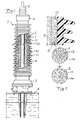
- Fig 1 illustrates an elongated member according to an embodiment of the invention in the form of a transformer bushing having an outer sleeve-like rigid ceramic or polymer insulator shell 1 with outer flanges 2, which shell may have a length in the order of 1 dm - 10 m and is secured at the ends to metal flanges 3, 4, which may be of aluminium.
- the conductor 5 is surrounded by electrical field distributing capacitors in the form of a number of layers 9 of for instance alternatingly paper and metal wound therearound. These number of layers and accordingly the number of capacitors are reduced at the end 7 distant to the connection of the bushing to the transformer casing 8 as well as at the end thereof immerged into an oil bath 25 inside the transformer casing. This means that the electric field will be substantially constant gradually from the conductor 5 and outwards towards the shell 1. Furthermore, the cone-like shape of the capacitor layer 9 results in a smooth electrical field in the axial direction inside the bushing.
- a gap 10 is formed inside the shell 1 next to the internal wall of the shell, and this gap is filled with a medium 11 of a material with electrically insulating properties.
- This material contains expanded hollow microspheres, filled with gas or a liquid/gas-mixture mixed into a silicon gel, or another type of gel. After this mixing the silicon gel cross-links, which results in a compressible gel, the function of which will be explained below with reference to fig 2.
- the total volume of the hollow spaces of the microspheres is at room temperature 10-50% of the total volume of said medium and accordingly of said gap.
- the silicon gel with the microspheres contained therein is filled into the gap to have an overpressure therein, i.e. influencing the internal walls 12 of said shell, with a pressure P of 0 ⁇ P ⁇ 2 bar at room temperature.
- the function of the medium 11 in said gap 10 will be as follows.
- the temperature of this medium may change as a consequence of changes of the outdoor temperature when said shell is located outdoors and as a consequence of changes of the intensity of a current flowing through the conductor 5. It is shown in fig 2 what happens when the temperature of said medium increases resulting in a change of the condition of said medium from A to B. Accordingly, the gel 13 will expand while compressing the microspheres 14 and by that reducing the volume thereof keeping any pressure built up inside the shell at an acceptable low level. The microspheres are in this way reversibly compressed, which means that they will expand and increase in volume when the temperature of said medium sinks again.
- Fig 3 illustrates a member 15 according to another embodiment of the invention which is also present in fig 1, designed to be arranged on the circumference of the bushing for tapping a voltage from this bushing.
- a wire 16 extending into the layer 9 of capacitors and connecting to a capacitor on a potential differing considerably from earth, which will be the potential of the outermost capacitor layer bearing against the metallic flange 17.
- this wire 16 has to be electrically insulated with respect to the flange 17, and a gap 10 surrounding this wire 16 is filled with a medium 11 of the type described above.
- this medium 11 will act according to above when the temperature thereof is changing protecting an insulator body 18 surrounding the wire against damage as a consequence of pressure built up inside the gap 10 filled with said medium.
- Fig 4 illustrates a member according to a third embodiment of the invention in the form of a cable termination. Parts thereof corresponding to part of the bushing in fig 1 have been provided with the same reference numerals.
- This cable termination has a cable clamp 20 at one end thereof, to which a high voltage cable 21, such as a PEX-cable, is connected.
- This clamp 20 is connected to a conductor tube 5, extending inside the ceramic shell 1 to the other end thereof for connection to an overhead line 22 of a high voltage network.
- the bottom end of the cable termination is preferably secured to a ground plate 23 by an aluminium flange 24.
- the gap 10 between the conductor 5 and the shell 1 is filled with a medium 11 of the type described above in connection with fig 1 and 2 resulting in the same behaviour and advantages as mentioned above.
- Said hollow spaces may have other shapes than as a sphere, and they may be closed cells formed and delimited by the material forming the rest of said medium.
Landscapes
- Insulators (AREA)
- Housings And Mounting Of Transformers (AREA)
- Gas-Insulated Switchgears (AREA)
- Installation Of Bus-Bars (AREA)
Abstract
Description
- The present invention relates to an elongated member having an outer sleeve-like rigid insulator shell surrounding a high voltage conductor extending in the longitudinal direction of the shell and a gap inside the shell next to the internal wall of the shell at least partially surrounding said conductor and filled with a medium of a material with electrically insulating properties.
- The invention is directed to any such member where a high voltage is to be shielded with respect to the environment for preventing flash-overs from occurring to equipment, casings or other objects normally being connected to earth.
- An example of such a member is a bushing connecting a transformer to a high voltage network, in which it is essential to shield the high voltage of the conductor to be connected to the high voltage network to a location at a considerable distance, such as for example 4 meters, from the transformer.
- Cable terminations and High voltage apparatuses are other examples of such members.
- A member of this type has to withstand large temperature changes over time. These temperature changes may be due to the fact that it is totally or at least partially located outdoors, where the temperature depending upon the time of the year may change between -40°C and +40°C. Furthermore, the load of said high voltage conductor may vary, i.e. the current flowing therethrough may vary so much that the temperature of this conductor and by that of the parts of said elongated member inside said shell may vary considerably. In fact, the temperature of the shell will be mainly determined by the temperature of the environment of said member, whereas the temperature of the internal parts thereof, such as of said medium, will also depend on the intensity of the current flowing through the conductor. The medium of a material with certain electrically insulating properties, which has to fill said gap, will tend to change in volume with the temperature, which means that a pressure will be built up inside the shell upon a temperature rise if the medium is totally enclosed in said shell. This pressure may cause the outer insulator shell to be damaged.
- There are two known solutions to this problem. The first is to construct the member with the outer insulator shell so that it is able to withstand the pressure built up, which is difficult and costly to obtain. The other solution is to construct the member so that the pressure built-up is taken care of, for instance by connecting said gap filled with a fluid to an expansion vessel, which is both complicated and expensive. Furthermore, this involves a risk of leakage of said medium, which may constitute a fire risk.
- The object of the present invention is to provide a member of the type defined in the introduction advising a different solution to the problem with temperature changes of said member and the parts thereof.
- This object is according to the invention obtained by providing such a member in which said medium is formed by an electrically insulating material containing hollow spaces at least partially filled with gas, in which said material is adapted to expand upon a temperature rise thereof by reversibly compressing said hollow spaces and reducing the volume thereof.
- This means that instead of a high pressure built up upon a temperature rise of said medium the material is allowed to expand in itself by compressing said hollow spaces, so that the pressure may be reduced. Thus, the insulator shell may be protected against damage without overdimensioning it, and no complicated and costly arrangements for taking care of a pressure built-up have to be accomplished.
- According to an embodiment of the invention said hollow spaces are formed by deformable spheres adapted to after deformation resume their shape when external compressive forces from said material are reduced as a consequence of a temperature decrease. This constitutes an advantageous way of obtaining said hollow spaces providing a flexible nature of said medium with respect to temperature changes. It is even possible that said hollow spaces expand and increase in volume with respect to a state thereof at room temperature when the temperature falls below room temperature.
- According to another embodiment of the invention said material is a cross-linked gel with microspheres embedded therein. The combination of such a gel with microspheres provides the possibility to conveniently select a relation of a total volume of said hollow spaces with respect to the total volume of said gap suitable for the intended use of said member.
- According to another embodiment of the invention said microspheres have a diameter of 10 µm - 100 µm when not deformed. It has turned out that these are suitable dimensions of such hollow spaces for ensuring the maintenance of excellent electrically insulating properties of said medium aimed at.
- According to another embodiment of the invention said microspheres are expanded microspheres.
- According to another embodiment of the invention said microspheres are filled with a mixture of liquid and gas, in which the gas content is adapted to increase with the temperature of said material and thereby of the microspheres. Thanks to the increase of gas content with a temperature increase the volume reduction of said microspheres is facilitated with increasing temperatures. According to another embodiment of the invention said microspheres are filled with only gas.
- According to another embodiment of the invention the total volume of said hollow spaces is at room temperature 10-50%, preferably 20-40%, of the total volume of said medium and accordingly of said gap. This means an ability of said material to expand considerably while reducing the volume of said hollow spaces without substantially increasing the pressure upon parts of the member defining said gap.
- According to another embodiment of the invention said medium is filled into said gap to have an overpressure therein, i.e. influencing the internal walls of said shell, with a pressure P of 0<P<2 bar at room temperature. Such an overpressure at room temperature has turned out to be sufficient for ensuring that the entire gap is totally filled with said medium also at lower temperatures of said member.
- According to another embodiment of the invention said conductor is a conductor tube extending through substantially the entire shell.
- According to a further embodiment of the invention said gap separates the internal walls of the shell from an active core of the member comprising said conductor. Thus, said gap has not to fill the entire volume between said conductor and the outer shell, and according to an embodiment of the invention said member is a bushing designed for leading a high voltage conductor through a wall and said active core then comprises electrical field distributing capacitor surrounding said conductor, so that the electrical field will be nearly constant from said conductor and outwards towards the insulator shell. "Wall" is here to be given a wide meaning and may just as well be a wall of a casing, such as a transformer casing, as a wall of a building.
- According to another embodiment of the invention said shell is a ceramic sleeve, preferably with outer flanges. This ceramic sleeve may at the ends thereof be secured to metal flanges, for instance of aluminium.
- According to another embodiment of the invention the member is designed to have said conductor on a system voltage of at least 12 kV, such as 12 kV-800 kV, especially 50 kV-800 kV. These are conceivable ranges for the voltage of the conductor in a member to which the present invention is directed.
- According to another embodiment of the invention said member is designed to have a current of at least 1A, such as 1 A-100 kA, especially 500 A-25 kA, to flow through the conductor thereof. Such current intensities may typically occur in applications where a member of this type is useful, and changes of these currents may cause considerable temperature changes of said medium in said gap.
- According to another embodiment of the invention the member is a bushing to be arranged at a high voltage converter station for leading a high voltage conductor through a wall of a current valve hall and outdoors or from one such hall to another such hall. The member may also be a bushing adapted to be connected to the outer casing of any high voltage apparatus, such as a bushing adapted to be connected to a high voltage disconnector, where there is a need to insulate a conductor with respect to an earthed plane it has to pass.
- According to another embodiment of the invention the member may be a transformer bushing or a generator bushing, or it may be a wall bushing.
- According to another embodiment of the invention said member is designed to be arranged on the circumference of a bushing for leading a high voltage conductor through a wall for tapping a voltage from this bushing. Temperature changes of the said electrically insulating medium of such a member may also constitute a severe problem with respect to pressure built-up wouldn't said material be able to expand by reducing the volume of said hollow spaces.
- According to another embodiment of the invention said member is designed as a cable termination adapted to have a high voltage cable connected to one end thereof. Such cable terminations may be used for connecting an electrical cable, such as a PEX-cable to a power line of a high voltage network, a transformer or a gas-insulated switchgear in which said member may be arranged to stand on the ground at the cable end thereof.
- The invention also relates to a use of a member according to the invention as a wall bushing, a transformer or a generator bushing or as a cable termination or as a high voltage apparatus.
- Further advantages as well as advantageous features of the invention will appear from the following description of embodiments thereof.
- With reference to the appended drawings, below follows a specific description of embodiments of the invention cited as examples.
- In the drawings:
- Fig 1
- shows a transformer bushing according to a first embodiment of the invention in a partially longitudinally sectioned view,
- Fig 2
- is an enlarged view of a part of the shell and portions inside thereof of the bushing according to fig 1 as well as two enlargements showing the structure of a medium of an electrically insulating material in said bushing at two different temperatures of said medium,
- Fig 3
- is a partially section view illustrating a member according to a second embodiment of the invention arranged on the circumference of a bushing for leading a high voltage conductor through a wall for tapping a voltage from this bushing, and
- Fig 4
- is a partially section view of a member according to a third embodiment of the invention in the form of a cable termination.
- Fig 1 illustrates an elongated member according to an embodiment of the invention in the form of a transformer bushing having an outer sleeve-like rigid ceramic or
polymer insulator shell 1 with outer flanges 2, which shell may have a length in the order of 1 dm - 10 m and is secured at the ends tometal flanges high voltage conductor 5 in the form of a tube, such as an aluminium or copper tube, extend throughout theentire shell 1 for connecting to the transformer at one end and to a high voltage conductor of a high voltage network at the other end (see contact pin 6). Theconductor 5 is surrounded by electrical field distributing capacitors in the form of a number of layers 9 of for instance alternatingly paper and metal wound therearound. These number of layers and accordingly the number of capacitors are reduced at the end 7 distant to the connection of the bushing to the transformer casing 8 as well as at the end thereof immerged into an oil bath 25 inside the transformer casing. This means that the electric field will be substantially constant gradually from theconductor 5 and outwards towards theshell 1. Furthermore, the cone-like shape of the capacitor layer 9 results in a smooth electrical field in the axial direction inside the bushing. In the radial direction the entire field will be taken by the bushing where the capacitor layer 9 is thick, whereas a part thereof will be taken by the bushing and a part by the air at the end 7 remote from earth potential and a part by the capacitor layer and a part by the oil bath at the other end. - Furthermore, a
gap 10 is formed inside theshell 1 next to the internal wall of the shell, and this gap is filled with a medium 11 of a material with electrically insulating properties. This material contains expanded hollow microspheres, filled with gas or a liquid/gas-mixture mixed into a silicon gel, or another type of gel. After this mixing the silicon gel cross-links, which results in a compressible gel, the function of which will be explained below with reference to fig 2. The total volume of the hollow spaces of the microspheres is at room temperature 10-50% of the total volume of said medium and accordingly of said gap. - The silicon gel with the microspheres contained therein is filled into the gap to have an overpressure therein, i.e. influencing the
internal walls 12 of said shell, with a pressure P of 0<P<2 bar at room temperature. This means in the case of a transformer bushing vertically directed as in fig 1 that the overpressure will be lower at the top end 7 than at the lower end owing to the influence of the gravitation. - The function of the medium 11 in said
gap 10 will be as follows. The temperature of this medium may change as a consequence of changes of the outdoor temperature when said shell is located outdoors and as a consequence of changes of the intensity of a current flowing through theconductor 5. It is shown in fig 2 what happens when the temperature of said medium increases resulting in a change of the condition of said medium from A to B. Accordingly, thegel 13 will expand while compressing themicrospheres 14 and by that reducing the volume thereof keeping any pressure built up inside the shell at an acceptable low level. The microspheres are in this way reversibly compressed, which means that they will expand and increase in volume when the temperature of said medium sinks again. - Fig 3 illustrates a
member 15 according to another embodiment of the invention which is also present in fig 1, designed to be arranged on the circumference of the bushing for tapping a voltage from this bushing. This is obtained by awire 16 extending into the layer 9 of capacitors and connecting to a capacitor on a potential differing considerably from earth, which will be the potential of the outermost capacitor layer bearing against themetallic flange 17. Thus, thiswire 16 has to be electrically insulated with respect to theflange 17, and agap 10 surrounding thiswire 16 is filled with a medium 11 of the type described above. Thus, this medium 11 will act according to above when the temperature thereof is changing protecting aninsulator body 18 surrounding the wire against damage as a consequence of pressure built up inside thegap 10 filled with said medium. - Fig 4 illustrates a member according to a third embodiment of the invention in the form of a cable termination. Parts thereof corresponding to part of the bushing in fig 1 have been provided with the same reference numerals. This cable termination has a
cable clamp 20 at one end thereof, to which ahigh voltage cable 21, such as a PEX-cable, is connected. Thisclamp 20 is connected to aconductor tube 5, extending inside theceramic shell 1 to the other end thereof for connection to anoverhead line 22 of a high voltage network. The bottom end of the cable termination is preferably secured to aground plate 23 by analuminium flange 24. Thegap 10 between theconductor 5 and theshell 1 is filled with a medium 11 of the type described above in connection with fig 1 and 2 resulting in the same behaviour and advantages as mentioned above. - The invention is of course not in any way restricted to the embodiments thereof described above, but many possibilities to modifications thereof would be apparent to a person with ordinary skill in the art without departing from the basic idea of the invention as defined in the appended claims.
- Said hollow spaces may have other shapes than as a sphere, and they may be closed cells formed and delimited by the material forming the rest of said medium.
Claims (29)
- An elongated member having an outer sleeve-like rigid insulator shell (1) surrounding a high voltage conductor (5, 16) extending in the longitudinal direction of the shell and a gap (10) inside the shell next to the internal wall of the shell at least partially surrounding said conductor and filled with a medium (11) of a material with electrically insulating properties, characterized in that said medium is formed by an electrically insulating material (13) containing hollow spaces (14) at least partially filled with gas, and that said material is adapted to expand upon a temperature rise thereof by reversibly compressing said hollow spaces and reducing the volume thereof.
- A member according to claim 1, characterized in that said hollow spaces are formed by deformable spheres (14) adapted to after deformation resume their shape when external compressive forces from said material (13) are reduced as a consequence of a temperature decrease.
- A member according to claim 2, characterized in that said material is a cross-linked gel (13) with microspheres (14) embedded therein.
- A member according to claim 3, characterized in that said microspheres (14) have a diameter of 10 µm -100 µm when not deformed.
- A member according to claim 3 or 4, characterized in that said gel (13) is a silicon gel.
- A member according to any of claims 3-5, characterized in that said microspheres (14) are expanded microspheres.
- A member according to any of claims 3-6, characterized in that said microspheres (14) are filled with a mixture of liquid and gas, in which the gas content is adapted to increase with the temperature of said material and thereby of the microspheres.
- A member according to any of claims 3-6, characterized in that said microspheres (14) are filled with only gas.
- A member according to any of the preceding claims, characterized in that the total volume of said hollow spaces (14) is at room temperature 10-50%, preferably 20-40%, of the total volume of said medium (11) and accordingly of said gap (10).
- A member according to any of the preceding claims, characterized in that said medium is filled into said gap to have an overpressure therein, i.e. influencing the internal walls of said shell, with a pressure P of 0<P<2 bar at room temperature.
- A member according to any of the preceding claims, characterized in that said conductor is a conductor tube (5) extending through substantially the entire shell (1).
- A member according to any of the preceding claims, characterized in that said gap (10) separates the internal walls of the shell (1) from an active core of the member comprising said conductor (5).
- A member according to any of the preceding claims, characterized in that said shell (1) is a ceramic or polymer sleeve, preferably with outer flanges (2).
- A member according to claim 13, characterized in that said ceramic or polymer sleeve (1) is at the ends thereof secured to metal flanges (3, 4).
- A member according to any of the preceding claims, characterized in that it is designed to have said conductor on a system voltage of at least 12 kV, such as 12 kV - 800 kV, especially 50 kV - 800 kV.
- A member according to any of the preceding claims, characterized in that it is designed to have a current of at least 1 A, such as 1 A - 100 kA, especially 500 A - 25 kA, to flow through the conductor thereof.
- A member according to any of the preceding claims, characterized in that it is a bushing designed for leading a high voltage conductor through a wall.
- A member according to claims 12 and 17, characterized in that said active core comprises electrical field distributing capacitors (9) surrounding said conductor (5).
- A member according to claim 17, characterized in that it is a bushing to be arranged at a high voltage converter station for leading a high voltage conductor through a wall of a current valve hall and outdoors or from one such hall to another such hall.
- A member according to claim 17, characterized in that it is a bushing adapted to be connected to the outer casing of any high voltage apparatus.
- A member according to claim 20, characterized in that it is a bushing adapted to be connected to a high voltage disconnector.
- A member according to claim 17, characterized in that it is a transformer bushing or a generator bushing.
- A member according to claim 17, characterized in that it is a wall bushing.
- A member according to any of the preceding claims, characterized in that it is designed to be arranged on the circumference of a bushing for leading a high voltage conductor through a wall for tapping a voltage from this bushing.
- A member according to any of claims 1-15, characterized in that it is designed as a cable termination adapted to have a high voltage cable connected to one end thereof.
- Use of a member according to any of claims 1-15 as a wall bushing.
- Use of a member according to any of claims 1-15 as a transformer or generator bushing.
- Use of a member according to any of claims 1-15 as a cable termination.
- Use of a member according to any of claims 1-15 as a high voltage apparatus.
Priority Applications (9)
| Application Number | Priority Date | Filing Date | Title |
|---|---|---|---|
| EP06112828.6A EP1848009B1 (en) | 2006-04-20 | 2006-04-20 | An elongated member and use thereof |
| KR1020087025230A KR101321222B1 (en) | 2006-04-20 | 2007-04-10 | An elongated member and use thereof |
| CA2649223A CA2649223C (en) | 2006-04-20 | 2007-04-10 | An elongated member and use thereof |
| PCT/EP2007/053442 WO2007122099A1 (en) | 2006-04-20 | 2007-04-10 | An elongated member and use thereof |
| JP2009505845A JP2009534787A (en) | 2006-04-20 | 2007-04-10 | Elongated member and use thereof |
| US12/297,765 US7939752B2 (en) | 2006-04-20 | 2007-04-10 | Elongated member and use thereof |
| RU2008144777/07A RU2428760C2 (en) | 2006-04-20 | 2007-04-10 | Extended element and its application |
| CN2007800138611A CN101427325B (en) | 2006-04-20 | 2007-04-10 | Extension parts and their uses |
| BRPI0710518A BRPI0710518B8 (en) | 2006-04-20 | 2007-04-10 | EXTENDED ELEMENT HAVING AN OUTER SLEEVE-TYPE RIGID INSULATING WRAP SURROUNDING A HIGH VOLTAGE CONDUCTOR |
Applications Claiming Priority (1)
| Application Number | Priority Date | Filing Date | Title |
|---|---|---|---|
| EP06112828.6A EP1848009B1 (en) | 2006-04-20 | 2006-04-20 | An elongated member and use thereof |
Publications (2)
| Publication Number | Publication Date |
|---|---|
| EP1848009A1 true EP1848009A1 (en) | 2007-10-24 |
| EP1848009B1 EP1848009B1 (en) | 2014-03-26 |
Family
ID=36950193
Family Applications (1)
| Application Number | Title | Priority Date | Filing Date |
|---|---|---|---|
| EP06112828.6A Expired - Lifetime EP1848009B1 (en) | 2006-04-20 | 2006-04-20 | An elongated member and use thereof |
Country Status (9)
| Country | Link |
|---|---|
| US (1) | US7939752B2 (en) |
| EP (1) | EP1848009B1 (en) |
| JP (1) | JP2009534787A (en) |
| KR (1) | KR101321222B1 (en) |
| CN (1) | CN101427325B (en) |
| BR (1) | BRPI0710518B8 (en) |
| CA (1) | CA2649223C (en) |
| RU (1) | RU2428760C2 (en) |
| WO (1) | WO2007122099A1 (en) |
Cited By (3)
| Publication number | Priority date | Publication date | Assignee | Title |
|---|---|---|---|---|
| CH698970A1 (en) * | 2008-06-04 | 2009-12-15 | Trench Switzerland Ag | High-voltage transducer with flexible insulation. |
| US20100200274A1 (en) * | 2007-09-20 | 2010-08-12 | Erik Jonsson | Electric Insulation Device And An Electric Device Provided Therewith |
| WO2024062207A1 (en) * | 2022-09-22 | 2024-03-28 | Arkema France | Electrical apparatus comprising at least one gelled material |
Families Citing this family (11)
| Publication number | Priority date | Publication date | Assignee | Title |
|---|---|---|---|---|
| CN101136280A (en) * | 2006-08-31 | 2008-03-05 | Abb技术有限公司 | High voltage equipment, high voltage bushing and method for assembling said equipment |
| US8766098B2 (en) | 2009-04-14 | 2014-07-01 | Alstom Grid | Folding high voltage insulating column |
| DE102010015729B4 (en) * | 2010-04-21 | 2015-01-22 | Maschinenfabrik Reinhausen Gmbh | High-voltage insulator |
| US8963015B2 (en) * | 2011-01-18 | 2015-02-24 | Fisher Controls International Llc | Capacitor coupled cable shield feedthrough |
| JP5740687B2 (en) * | 2011-01-18 | 2015-06-24 | 株式会社ダイヘン | Ground-mounted transformer device |
| US9078346B2 (en) * | 2013-03-11 | 2015-07-07 | Varian Semiconductor Equipment Associates, Inc. | Insulator protection |
| EP2924698B1 (en) * | 2014-03-27 | 2018-11-21 | ABB Schweiz AG | Oil-oil feedthrough and oil transformer |
| CN108257741B (en) * | 2018-03-27 | 2021-04-23 | 江苏神马电力股份有限公司 | Post insulator and insulating post |
| DE102019125962A1 (en) | 2019-09-26 | 2021-04-01 | Maschinenfabrik Reinhausen Gmbh | Dry, syntactic foam as an electrically insulating material |
| CN111734950A (en) * | 2020-07-01 | 2020-10-02 | 西安维国电子科技有限公司 | Method and device for filling and recovering electric insulating gas in closed space |
| US20250232892A1 (en) * | 2024-01-11 | 2025-07-17 | Te Connectivity Solutions Gmbh | Dielectric body for an electrical component |
Citations (2)
| Publication number | Priority date | Publication date | Assignee | Title |
|---|---|---|---|---|
| GB1445025A (en) * | 1973-10-26 | 1976-08-04 | Asea Ab | Electrically-insulating bushings for high voltage equipment |
| EP0971372A1 (en) | 1998-07-10 | 2000-01-12 | ABB Research Ltd. | Electric device with silicone insulating filler |
Family Cites Families (11)
| Publication number | Priority date | Publication date | Assignee | Title |
|---|---|---|---|---|
| SE386762B (en) * | 1974-11-19 | 1976-08-16 | Asea Ab | PERFORMANCE FOR ELECTRICAL CONNECTION |
| SU626442A1 (en) * | 1976-02-26 | 1978-09-30 | Предприятие П/Я А-7809 | Through insulator for explosion-proof electric equipment |
| JPS61161830U (en) * | 1985-03-27 | 1986-10-07 | ||
| US5466890A (en) * | 1994-03-22 | 1995-11-14 | Cooper Industries, Inc. | Expansion joint for an electrical conduit which is electrically grounded through the expansion joint |
| US5466891A (en) * | 1994-04-08 | 1995-11-14 | Abb Power T&D Company Inc. | Conical composite SF6 high voltage bushing with floating shield |
| JPH0963381A (en) * | 1995-08-25 | 1997-03-07 | Ngk Insulators Ltd | Suspended insulator |
| US6140573A (en) * | 1998-05-29 | 2000-10-31 | Siemens Aktiengesellschaft | Hollow core composite bushings |
| EP1130605A1 (en) * | 2000-03-01 | 2001-09-05 | Wermelinger AG | Method for manufacturing a high-voltage composite insulator, high-voltage insulator and plastic for use in the method, method for manufacturing a non-cylindrical component |
| CN2453521Y (en) * | 2000-12-07 | 2001-10-10 | 南京供电局 | Sleeve insulator with current mutual inductor used for distribution transformer |
| DE10142856A1 (en) * | 2001-08-28 | 2003-03-20 | Siemens Ag | Disc shaped support insulator for three phase encapsulated high voltage installation has corrugated form |
| DE102006036233B4 (en) * | 2006-08-03 | 2008-03-27 | Nkt Cables Gmbh | Outdoor termination |
-
2006
- 2006-04-20 EP EP06112828.6A patent/EP1848009B1/en not_active Expired - Lifetime
-
2007
- 2007-04-10 KR KR1020087025230A patent/KR101321222B1/en active Active
- 2007-04-10 US US12/297,765 patent/US7939752B2/en active Active
- 2007-04-10 CN CN2007800138611A patent/CN101427325B/en active Active
- 2007-04-10 WO PCT/EP2007/053442 patent/WO2007122099A1/en not_active Ceased
- 2007-04-10 BR BRPI0710518A patent/BRPI0710518B8/en active IP Right Grant
- 2007-04-10 RU RU2008144777/07A patent/RU2428760C2/en active
- 2007-04-10 JP JP2009505845A patent/JP2009534787A/en not_active Withdrawn
- 2007-04-10 CA CA2649223A patent/CA2649223C/en active Active
Patent Citations (2)
| Publication number | Priority date | Publication date | Assignee | Title |
|---|---|---|---|---|
| GB1445025A (en) * | 1973-10-26 | 1976-08-04 | Asea Ab | Electrically-insulating bushings for high voltage equipment |
| EP0971372A1 (en) | 1998-07-10 | 2000-01-12 | ABB Research Ltd. | Electric device with silicone insulating filler |
Cited By (5)
| Publication number | Priority date | Publication date | Assignee | Title |
|---|---|---|---|---|
| US20100200274A1 (en) * | 2007-09-20 | 2010-08-12 | Erik Jonsson | Electric Insulation Device And An Electric Device Provided Therewith |
| US8637773B2 (en) * | 2007-09-20 | 2014-01-28 | Abb Research Ltd. | Electric insulation device and an electric device provided therewith |
| CH698970A1 (en) * | 2008-06-04 | 2009-12-15 | Trench Switzerland Ag | High-voltage transducer with flexible insulation. |
| WO2024062207A1 (en) * | 2022-09-22 | 2024-03-28 | Arkema France | Electrical apparatus comprising at least one gelled material |
| FR3140201A1 (en) * | 2022-09-22 | 2024-03-29 | Arkema France | Electrical apparatus comprising at least one gelled material |
Also Published As
| Publication number | Publication date |
|---|---|
| BRPI0710518A2 (en) | 2011-08-16 |
| CN101427325A (en) | 2009-05-06 |
| US20090173515A1 (en) | 2009-07-09 |
| KR20080110821A (en) | 2008-12-19 |
| RU2428760C2 (en) | 2011-09-10 |
| EP1848009B1 (en) | 2014-03-26 |
| RU2008144777A (en) | 2010-05-27 |
| JP2009534787A (en) | 2009-09-24 |
| CA2649223C (en) | 2014-12-09 |
| BRPI0710518B1 (en) | 2018-03-06 |
| US7939752B2 (en) | 2011-05-10 |
| WO2007122099A1 (en) | 2007-11-01 |
| CA2649223A1 (en) | 2007-11-01 |
| BRPI0710518B8 (en) | 2022-12-13 |
| CN101427325B (en) | 2012-08-22 |
| KR101321222B1 (en) | 2013-10-23 |
Similar Documents
| Publication | Publication Date | Title |
|---|---|---|
| US7939752B2 (en) | Elongated member and use thereof | |
| CA2999203C (en) | A cable fitting for connecting a high-voltage cable to a high-voltage component | |
| US6074229A (en) | Cable termination | |
| BG63442B1 (en) | Dc transformer/converter | |
| CN110994506A (en) | A high-voltage bushing and method for passing voltage and current through a building or wall | |
| CN106469594B (en) | Bushing shell for transformer | |
| EP2117016A1 (en) | Draw rod mounting arrangement for a high voltage bushing, high voltage bushing comprising such arrangement and high voltage device comprising bushing with such arrangement | |
| CN201503735U (en) | HV DC Bushing | |
| JP5114331B2 (en) | Gas-oil direct connection three-phase batch type insulation sorting device for electrical equipment | |
| CN1967955B (en) | Connection structure between gas insulated switchgear and oil-immersed transformer | |
| JP7760583B2 (en) | Coated conductors in high voltage equipment and methods for increasing dielectric strength | |
| JP4253434B2 (en) | Compound insulation type gas insulated switchgear | |
| CN215641633U (en) | Composite insulator performance test platform for metal shielding type sleeve | |
| US10818434B2 (en) | Adaptor for a capacitor | |
| US4097681A (en) | Interface for high voltage oil-filled and gas-filled apparatus | |
| RU2319242C1 (en) | Polymeric support insulator characterized in enhanced reliability | |
| SE512105C2 (en) | switchgear Station | |
| EP4203212A1 (en) | Switchgear device and method of assembling thereof | |
| EP3826034A1 (en) | Electrical bushing having enhanced thermal performance | |
| RU161914U1 (en) | PASS INSULATOR | |
| Pryor et al. | Overvoltage protection in open air terminal and GIS in the 145 kV distribution system | |
| MXPA98009865A (en) | Transformer / reac | |
| JPH03251016A (en) | High-tension electrical-equipment | |
| SE508556C2 (en) | Power transformer and reactor with windings with conductors |
Legal Events
| Date | Code | Title | Description |
|---|---|---|---|
| PUAI | Public reference made under article 153(3) epc to a published international application that has entered the european phase |
Free format text: ORIGINAL CODE: 0009012 |
|
| AK | Designated contracting states |
Kind code of ref document: A1 Designated state(s): AT BE BG CH CY CZ DE DK EE ES FI FR GB GR HU IE IS IT LI LT LU LV MC NL PL PT RO SE SI SK TR |
|
| AX | Request for extension of the european patent |
Extension state: AL BA HR MK YU |
|
| 17P | Request for examination filed |
Effective date: 20080418 |
|
| AKX | Designation fees paid |
Designated state(s): AT BE BG CH CY CZ DE DK EE ES FI FR GB GR HU IE IS IT LI LT LU LV MC NL PL PT RO SE SI SK TR |
|
| 17Q | First examination report despatched |
Effective date: 20080716 |
|
| GRAP | Despatch of communication of intention to grant a patent |
Free format text: ORIGINAL CODE: EPIDOSNIGR1 |
|
| INTG | Intention to grant announced |
Effective date: 20131111 |
|
| GRAS | Grant fee paid |
Free format text: ORIGINAL CODE: EPIDOSNIGR3 |
|
| GRAA | (expected) grant |
Free format text: ORIGINAL CODE: 0009210 |
|
| AK | Designated contracting states |
Kind code of ref document: B1 Designated state(s): AT BE BG CH CY CZ DE DK EE ES FI FR GB GR HU IE IS IT LI LT LU LV MC NL PL PT RO SE SI SK TR |
|
| REG | Reference to a national code |
Ref country code: GB Ref legal event code: FG4D |
|
| REG | Reference to a national code |
Ref country code: CH Ref legal event code: EP |
|
| REG | Reference to a national code |
Ref country code: AT Ref legal event code: REF Ref document number: 659346 Country of ref document: AT Kind code of ref document: T Effective date: 20140415 |
|
| REG | Reference to a national code |
Ref country code: IE Ref legal event code: FG4D |
|
| REG | Reference to a national code |
Ref country code: DE Ref legal event code: R096 Ref document number: 602006040808 Country of ref document: DE Effective date: 20140508 |
|
| PG25 | Lapsed in a contracting state [announced via postgrant information from national office to epo] |
Ref country code: LT Free format text: LAPSE BECAUSE OF FAILURE TO SUBMIT A TRANSLATION OF THE DESCRIPTION OR TO PAY THE FEE WITHIN THE PRESCRIBED TIME-LIMIT Effective date: 20140326 |
|
| REG | Reference to a national code |
Ref country code: AT Ref legal event code: MK05 Ref document number: 659346 Country of ref document: AT Kind code of ref document: T Effective date: 20140326 |
|
| REG | Reference to a national code |
Ref country code: NL Ref legal event code: VDEP Effective date: 20140326 |
|
| REG | Reference to a national code |
Ref country code: LT Ref legal event code: MG4D |
|
| PG25 | Lapsed in a contracting state [announced via postgrant information from national office to epo] |
Ref country code: SE Free format text: LAPSE BECAUSE OF FAILURE TO SUBMIT A TRANSLATION OF THE DESCRIPTION OR TO PAY THE FEE WITHIN THE PRESCRIBED TIME-LIMIT Effective date: 20140326 Ref country code: FI Free format text: LAPSE BECAUSE OF FAILURE TO SUBMIT A TRANSLATION OF THE DESCRIPTION OR TO PAY THE FEE WITHIN THE PRESCRIBED TIME-LIMIT Effective date: 20140326 |
|
| PG25 | Lapsed in a contracting state [announced via postgrant information from national office to epo] |
Ref country code: LV Free format text: LAPSE BECAUSE OF FAILURE TO SUBMIT A TRANSLATION OF THE DESCRIPTION OR TO PAY THE FEE WITHIN THE PRESCRIBED TIME-LIMIT Effective date: 20140326 |
|
| PG25 | Lapsed in a contracting state [announced via postgrant information from national office to epo] |
Ref country code: EE Free format text: LAPSE BECAUSE OF FAILURE TO SUBMIT A TRANSLATION OF THE DESCRIPTION OR TO PAY THE FEE WITHIN THE PRESCRIBED TIME-LIMIT Effective date: 20140326 Ref country code: BG Free format text: LAPSE BECAUSE OF FAILURE TO SUBMIT A TRANSLATION OF THE DESCRIPTION OR TO PAY THE FEE WITHIN THE PRESCRIBED TIME-LIMIT Effective date: 20140626 Ref country code: CZ Free format text: LAPSE BECAUSE OF FAILURE TO SUBMIT A TRANSLATION OF THE DESCRIPTION OR TO PAY THE FEE WITHIN THE PRESCRIBED TIME-LIMIT Effective date: 20140326 Ref country code: NL Free format text: LAPSE BECAUSE OF FAILURE TO SUBMIT A TRANSLATION OF THE DESCRIPTION OR TO PAY THE FEE WITHIN THE PRESCRIBED TIME-LIMIT Effective date: 20140326 Ref country code: IS Free format text: LAPSE BECAUSE OF FAILURE TO SUBMIT A TRANSLATION OF THE DESCRIPTION OR TO PAY THE FEE WITHIN THE PRESCRIBED TIME-LIMIT Effective date: 20140726 Ref country code: BE Free format text: LAPSE BECAUSE OF FAILURE TO SUBMIT A TRANSLATION OF THE DESCRIPTION OR TO PAY THE FEE WITHIN THE PRESCRIBED TIME-LIMIT Effective date: 20140326 Ref country code: RO Free format text: LAPSE BECAUSE OF FAILURE TO SUBMIT A TRANSLATION OF THE DESCRIPTION OR TO PAY THE FEE WITHIN THE PRESCRIBED TIME-LIMIT Effective date: 20140326 Ref country code: CY Free format text: LAPSE BECAUSE OF FAILURE TO SUBMIT A TRANSLATION OF THE DESCRIPTION OR TO PAY THE FEE WITHIN THE PRESCRIBED TIME-LIMIT Effective date: 20140326 |
|
| PG25 | Lapsed in a contracting state [announced via postgrant information from national office to epo] |
Ref country code: AT Free format text: LAPSE BECAUSE OF FAILURE TO SUBMIT A TRANSLATION OF THE DESCRIPTION OR TO PAY THE FEE WITHIN THE PRESCRIBED TIME-LIMIT Effective date: 20140326 Ref country code: MC Free format text: LAPSE BECAUSE OF FAILURE TO SUBMIT A TRANSLATION OF THE DESCRIPTION OR TO PAY THE FEE WITHIN THE PRESCRIBED TIME-LIMIT Effective date: 20140326 Ref country code: SK Free format text: LAPSE BECAUSE OF FAILURE TO SUBMIT A TRANSLATION OF THE DESCRIPTION OR TO PAY THE FEE WITHIN THE PRESCRIBED TIME-LIMIT Effective date: 20140326 Ref country code: ES Free format text: LAPSE BECAUSE OF FAILURE TO SUBMIT A TRANSLATION OF THE DESCRIPTION OR TO PAY THE FEE WITHIN THE PRESCRIBED TIME-LIMIT Effective date: 20140326 Ref country code: PL Free format text: LAPSE BECAUSE OF FAILURE TO SUBMIT A TRANSLATION OF THE DESCRIPTION OR TO PAY THE FEE WITHIN THE PRESCRIBED TIME-LIMIT Effective date: 20140326 |
|
| PG25 | Lapsed in a contracting state [announced via postgrant information from national office to epo] |
Ref country code: PT Free format text: LAPSE BECAUSE OF FAILURE TO SUBMIT A TRANSLATION OF THE DESCRIPTION OR TO PAY THE FEE WITHIN THE PRESCRIBED TIME-LIMIT Effective date: 20140728 |
|
| REG | Reference to a national code |
Ref country code: DE Ref legal event code: R097 Ref document number: 602006040808 Country of ref document: DE |
|
| REG | Reference to a national code |
Ref country code: IE Ref legal event code: MM4A |
|
| PG25 | Lapsed in a contracting state [announced via postgrant information from national office to epo] |
Ref country code: DK Free format text: LAPSE BECAUSE OF FAILURE TO SUBMIT A TRANSLATION OF THE DESCRIPTION OR TO PAY THE FEE WITHIN THE PRESCRIBED TIME-LIMIT Effective date: 20140326 |
|
| PLBE | No opposition filed within time limit |
Free format text: ORIGINAL CODE: 0009261 |
|
| STAA | Information on the status of an ep patent application or granted ep patent |
Free format text: STATUS: NO OPPOSITION FILED WITHIN TIME LIMIT |
|
| 26N | No opposition filed |
Effective date: 20150106 |
|
| REG | Reference to a national code |
Ref country code: DE Ref legal event code: R097 Ref document number: 602006040808 Country of ref document: DE Effective date: 20150106 |
|
| PG25 | Lapsed in a contracting state [announced via postgrant information from national office to epo] |
Ref country code: IE Free format text: LAPSE BECAUSE OF NON-PAYMENT OF DUE FEES Effective date: 20140420 |
|
| PG25 | Lapsed in a contracting state [announced via postgrant information from national office to epo] |
Ref country code: SI Free format text: LAPSE BECAUSE OF FAILURE TO SUBMIT A TRANSLATION OF THE DESCRIPTION OR TO PAY THE FEE WITHIN THE PRESCRIBED TIME-LIMIT Effective date: 20140326 |
|
| REG | Reference to a national code |
Ref country code: FR Ref legal event code: PLFP Year of fee payment: 11 |
|
| PG25 | Lapsed in a contracting state [announced via postgrant information from national office to epo] |
Ref country code: GR Free format text: LAPSE BECAUSE OF FAILURE TO SUBMIT A TRANSLATION OF THE DESCRIPTION OR TO PAY THE FEE WITHIN THE PRESCRIBED TIME-LIMIT Effective date: 20140627 |
|
| PG25 | Lapsed in a contracting state [announced via postgrant information from national office to epo] |
Ref country code: TR Free format text: LAPSE BECAUSE OF FAILURE TO SUBMIT A TRANSLATION OF THE DESCRIPTION OR TO PAY THE FEE WITHIN THE PRESCRIBED TIME-LIMIT Effective date: 20140326 Ref country code: HU Free format text: LAPSE BECAUSE OF FAILURE TO SUBMIT A TRANSLATION OF THE DESCRIPTION OR TO PAY THE FEE WITHIN THE PRESCRIBED TIME-LIMIT; INVALID AB INITIO Effective date: 20060420 Ref country code: LU Free format text: LAPSE BECAUSE OF NON-PAYMENT OF DUE FEES Effective date: 20140420 |
|
| REG | Reference to a national code |
Ref country code: FR Ref legal event code: PLFP Year of fee payment: 12 |
|
| REG | Reference to a national code |
Ref country code: DE Ref legal event code: R081 Ref document number: 602006040808 Country of ref document: DE Owner name: HITACHI ENERGY SWITZERLAND AG, CH Free format text: FORMER OWNER: ABB TECHNOLOGY LTD., ZUERICH, CH Ref country code: DE Ref legal event code: R081 Ref document number: 602006040808 Country of ref document: DE Owner name: ABB SCHWEIZ AG, CH Free format text: FORMER OWNER: ABB TECHNOLOGY LTD., ZUERICH, CH Ref country code: DE Ref legal event code: R081 Ref document number: 602006040808 Country of ref document: DE Owner name: ABB POWER GRIDS SWITZERLAND AG, CH Free format text: FORMER OWNER: ABB TECHNOLOGY LTD., ZUERICH, CH |
|
| REG | Reference to a national code |
Ref country code: CH Ref legal event code: PFUS Owner name: ABB SCHWEIZ AG, CH Free format text: FORMER OWNER: ABB TECHNOLOGY LTD, CH |
|
| REG | Reference to a national code |
Ref country code: FR Ref legal event code: PLFP Year of fee payment: 13 |
|
| REG | Reference to a national code |
Ref country code: GB Ref legal event code: 732E Free format text: REGISTERED BETWEEN 20180426 AND 20180502 |
|
| REG | Reference to a national code |
Ref country code: FR Ref legal event code: TP Owner name: ABB SCHWEIZ AG, CH Effective date: 20180912 |
|
| REG | Reference to a national code |
Ref country code: CH Ref legal event code: PUE Owner name: ABB POWER GRIDS SWITZERLAND AG, CH Free format text: FORMER OWNER: ABB SCHWEIZ AG, CH |
|
| REG | Reference to a national code |
Ref country code: DE Ref legal event code: R081 Ref document number: 602006040808 Country of ref document: DE Owner name: HITACHI ENERGY SWITZERLAND AG, CH Free format text: FORMER OWNER: ABB SCHWEIZ AG, BADEN, CH Ref country code: DE Ref legal event code: R081 Ref document number: 602006040808 Country of ref document: DE Owner name: HITACHI ENERGY LTD, CH Free format text: FORMER OWNER: ABB SCHWEIZ AG, BADEN, CH Ref country code: DE Ref legal event code: R081 Ref document number: 602006040808 Country of ref document: DE Owner name: ABB POWER GRIDS SWITZERLAND AG, CH Free format text: FORMER OWNER: ABB SCHWEIZ AG, BADEN, CH |
|
| REG | Reference to a national code |
Ref country code: GB Ref legal event code: 732E Free format text: REGISTERED BETWEEN 20210909 AND 20210915 |
|
| REG | Reference to a national code |
Ref country code: DE Ref legal event code: R081 Ref document number: 602006040808 Country of ref document: DE Owner name: HITACHI ENERGY SWITZERLAND AG, CH Free format text: FORMER OWNER: ABB POWER GRIDS SWITZERLAND AG, BADEN, CH Ref country code: DE Ref legal event code: R081 Ref document number: 602006040808 Country of ref document: DE Owner name: HITACHI ENERGY LTD, CH Free format text: FORMER OWNER: ABB POWER GRIDS SWITZERLAND AG, BADEN, CH |
|
| P01 | Opt-out of the competence of the unified patent court (upc) registered |
Effective date: 20230527 |
|
| REG | Reference to a national code |
Ref country code: DE Ref legal event code: R082 Ref document number: 602006040808 Country of ref document: DE Representative=s name: DENNEMEYER & ASSOCIATES RECHTSANWALTSGESELLSCH, DE Ref country code: DE Ref legal event code: R082 Ref document number: 602006040808 Country of ref document: DE Representative=s name: DENNEMEYER & ASSOCIATES S.A., DE Ref country code: DE Ref legal event code: R081 Ref document number: 602006040808 Country of ref document: DE Owner name: HITACHI ENERGY LTD, CH Free format text: FORMER OWNER: HITACHI ENERGY SWITZERLAND AG, BADEN, CH |
|
| REG | Reference to a national code |
Ref country code: GB Ref legal event code: 732E Free format text: REGISTERED BETWEEN 20240718 AND 20240724 |
|
| REG | Reference to a national code |
Ref country code: DE Ref legal event code: R082 Ref document number: 602006040808 Country of ref document: DE Representative=s name: DENNEMEYER & ASSOCIATES RECHTSANWALTSGESELLSCH, DE |
|
| PGFP | Annual fee paid to national office [announced via postgrant information from national office to epo] |
Ref country code: DE Payment date: 20250422 Year of fee payment: 20 |
|
| PGFP | Annual fee paid to national office [announced via postgrant information from national office to epo] |
Ref country code: GB Payment date: 20250418 Year of fee payment: 20 |
|
| PGFP | Annual fee paid to national office [announced via postgrant information from national office to epo] |
Ref country code: IT Payment date: 20250424 Year of fee payment: 20 |
|
| PGFP | Annual fee paid to national office [announced via postgrant information from national office to epo] |
Ref country code: FR Payment date: 20250423 Year of fee payment: 20 |
|
| PGFP | Annual fee paid to national office [announced via postgrant information from national office to epo] |
Ref country code: CH Payment date: 20250501 Year of fee payment: 20 |
|
| REG | Reference to a national code |
Ref country code: CH Ref legal event code: H14 Free format text: ST27 STATUS EVENT CODE: U-0-0-H10-H14 (AS PROVIDED BY THE NATIONAL OFFICE) Effective date: 20260420 Ref country code: DE Ref legal event code: R071 Ref document number: 602006040808 Country of ref document: DE |