EP1847742A2 - Solenoid-operated valve with coil for sensing plunger position - Google Patents
Solenoid-operated valve with coil for sensing plunger position Download PDFInfo
- Publication number
- EP1847742A2 EP1847742A2 EP20070075249 EP07075249A EP1847742A2 EP 1847742 A2 EP1847742 A2 EP 1847742A2 EP 20070075249 EP20070075249 EP 20070075249 EP 07075249 A EP07075249 A EP 07075249A EP 1847742 A2 EP1847742 A2 EP 1847742A2
- Authority
- EP
- European Patent Office
- Prior art keywords
- plunger
- valve
- segment
- position sensing
- rod
- Prior art date
- Legal status (The legal status is an assumption and is not a legal conclusion. Google has not performed a legal analysis and makes no representation as to the accuracy of the status listed.)
- Withdrawn
Links
Images


Classifications
-
- F—MECHANICAL ENGINEERING; LIGHTING; HEATING; WEAPONS; BLASTING
- F16—ENGINEERING ELEMENTS AND UNITS; GENERAL MEASURES FOR PRODUCING AND MAINTAINING EFFECTIVE FUNCTIONING OF MACHINES OR INSTALLATIONS; THERMAL INSULATION IN GENERAL
- F16K—VALVES; TAPS; COCKS; ACTUATING-FLOATS; DEVICES FOR VENTING OR AERATING
- F16K31/00—Actuating devices; Operating means; Releasing devices
- F16K31/02—Actuating devices; Operating means; Releasing devices electric; magnetic
- F16K31/06—Actuating devices; Operating means; Releasing devices electric; magnetic using a magnet, e.g. diaphragm valves, cutting off by means of a liquid
-
- F—MECHANICAL ENGINEERING; LIGHTING; HEATING; WEAPONS; BLASTING
- F16—ENGINEERING ELEMENTS AND UNITS; GENERAL MEASURES FOR PRODUCING AND MAINTAINING EFFECTIVE FUNCTIONING OF MACHINES OR INSTALLATIONS; THERMAL INSULATION IN GENERAL
- F16K—VALVES; TAPS; COCKS; ACTUATING-FLOATS; DEVICES FOR VENTING OR AERATING
- F16K37/00—Special means in or on valves or other cut-off apparatus for indicating or recording operation thereof, or for enabling an alarm to be given
- F16K37/0025—Electrical or magnetic means
- F16K37/0041—Electrical or magnetic means for measuring valve parameters
-
- H—ELECTRICITY
- H01—ELECTRIC ELEMENTS
- H01F—MAGNETS; INDUCTANCES; TRANSFORMERS; SELECTION OF MATERIALS FOR THEIR MAGNETIC PROPERTIES
- H01F7/00—Magnets
- H01F7/06—Electromagnets; Actuators including electromagnets
- H01F7/08—Electromagnets; Actuators including electromagnets with armatures
- H01F7/16—Rectilinearly-movable armatures
- H01F7/1607—Armatures entering the winding
-
- H—ELECTRICITY
- H01—ELECTRIC ELEMENTS
- H01F—MAGNETS; INDUCTANCES; TRANSFORMERS; SELECTION OF MATERIALS FOR THEIR MAGNETIC PROPERTIES
- H01F7/00—Magnets
- H01F7/06—Electromagnets; Actuators including electromagnets
- H01F7/08—Electromagnets; Actuators including electromagnets with armatures
- H01F7/18—Circuit arrangements for obtaining desired operating characteristics, e.g. for slow operation, for sequential energisation of windings, for high-speed energisation of windings
- H01F7/1844—Monitoring or fail-safe circuits
- H01F2007/185—Monitoring or fail-safe circuits with armature position measurement
-
- H—ELECTRICITY
- H01—ELECTRIC ELEMENTS
- H01F—MAGNETS; INDUCTANCES; TRANSFORMERS; SELECTION OF MATERIALS FOR THEIR MAGNETIC PROPERTIES
- H01F7/00—Magnets
- H01F7/06—Electromagnets; Actuators including electromagnets
- H01F7/08—Electromagnets; Actuators including electromagnets with armatures
- H01F7/13—Electromagnets; Actuators including electromagnets with armatures characterised by pulling-force characteristic
-
- Y—GENERAL TAGGING OF NEW TECHNOLOGICAL DEVELOPMENTS; GENERAL TAGGING OF CROSS-SECTIONAL TECHNOLOGIES SPANNING OVER SEVERAL SECTIONS OF THE IPC; TECHNICAL SUBJECTS COVERED BY FORMER USPC CROSS-REFERENCE ART COLLECTIONS [XRACs] AND DIGESTS
- Y10—TECHNICAL SUBJECTS COVERED BY FORMER USPC
- Y10T—TECHNICAL SUBJECTS COVERED BY FORMER US CLASSIFICATION
- Y10T137/00—Fluid handling
- Y10T137/8158—With indicator, register, recorder, alarm or inspection means
- Y10T137/8225—Position or extent of motion indicator
- Y10T137/8242—Electrical
Definitions
- the present invention relates generally to solenoid-operated valves, and more particularly to sensing the position of the plunger of a vehicle valve.
- Modem vehicles have many control systems in which a controller, in response to sensor signals, actuates vehicle components to control the vehicle.
- an engine control module ECM
- ECM engine control module
- Some applications where actuators are utilized require armature position sensing to help protect the system against severe failure modes. Such is the case for valves that are used to direct fluid to the engine cylinders to help cool and lubricate them. Closed-loop feedback is used to detect whether the actuator function has degraded or been lost.
- a need for simply, inexpensively, and elegantly indicating valve position is required.
- a valve has a valve body and a plunger disposed in the valve body and reciprocally movable therein.
- An actuating solenoid is disposed in a surrounding relationship with the plunger and is energizable to cause the plunger to move, while a position sensing coil is also disposed in a surrounding relationship with the plunger and outputs a signal representative of the position of the plunger.
- the plunger may be formed with a first segment and a second segment having a diameter smaller than the diameter of the first segment, with the actuating solenoid surrounding the first segment and the position sensing coil surrounding the second segment.
- the actuating solenoid and position sensing coil can be coaxial with each other, and if desired the position sensing coil can have a smaller diameter than the actuating solenoid.
- a rod may be centrally disposed in the plunger and staked thereto.
- the rod extends through a stop that is press-fit into the valve body, and the rod terminates in a poppet.
- a valve has an actuating solenoid, a position sensing coil axially spaced from the actuating solenoid, and a plunger axially movable centrally in the actuating solenoid and the position sensing coil.
- a valve has a plunger, electrically energizable actuating means for moving the plunger, and coil means for sensing a position of the plunger.
- the present invention is intended for application in automotive vehicle suspension systems and will be described in that context. It is to be understood, however, that the present invention could also be successfully applied in many other applications.
- a valve 10 that includes a rigid valve body 12 containing the below-described plunger structures that alter fluid flow paths in a fluid flow portion 13 of the valve in accordance with principles known in the art.
- An actuating solenoid 14 and a position sensing coil 16 are operably engaged with a plunger in the body 12 as set forth further below.
- the actuating solenoid 14 can be energized and deenergized under the control of a controller 18 such as an engine control module (ECM) to move below-described components within the valve body 12 to selectively port hydraulic fluid from a fluid source 20 to and from a hydraulic component 22, such as a vehicle automatic transmission or other vehicle hydraulically-operated component.
- ECM engine control module
- the position sensing coil 16 can send a position signal to the controller 18 for, e.g., monitoring the valve position and/or alarming if the sensed valve position is not an expected position and/or displaying an indication of valve position.
- FIG. 2 illustrates details of the valve.
- the valve is externally housed by the valve body 12.
- the valve body 12 may have a set of threads 24 on one end that may extend into another valve body (not shown).
- an external o-ring 26 fits over the valve body 12 and is set next to the set of threads 24. Extending out of the end of the valve body 12 with the set of threads 24 is a poppet 28.
- a rod 30 is centrally affixed to the poppet 28 and has a smaller diameter than the poppet 28.
- the rod 30 extends down the center of the valve 10 through an immovable stop 32 that is affixed with the valve body 12 by, e.g., press-fitting and that radially bears the rod 30.
- the rod 30 is bound to a movable plunger 34 by a bond structure 36, which can be, in one non-limiting implementation, staking.
- the plunger 34 can be moved by the energizable actuator solenoid 14.
- a frame 39 Surrounding the actuator solenoid 14 and disposed within or otherwise coupled to the valve body 12 is a frame 39. Coaxially aligned with the frame 39 is a secondary plate 41 with a diameter as large as that of the actuator solenoid 14.
- the actuator solenoid 14 is disposed in a surrounding relationship with a first, relatively (radially) large segment 34a of the plunger 34.
- the plunger 34 is also formed with a second segment 34b that has a smaller diameter than the first segment 34a and that is surrounded by the position sensing coil 16.
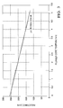
- the position sensing coil 16 is coaxially aligned with the actuator solenoid 14 so that it outputs a signal that varies linearly with the position of the plunger 34 as shown in Figure 3.
- the position sensing coil 16 also has a smaller inside diameter than the actuator solenoid 14 so as to be closely juxtaposed with the radially smaller second segment 34b of the plunger 34.
- a spring 42 may be coaxially aligned with the actuator solenoid 14 and disposed around the rod 30 to urge the plunger to the right looking down in Figure 2.
- the position sensing coil 16 surrounds the path of the end of the plunger 34 and has a displacement sensing magnetic flux path 44 (indicated by four arrows).
- the actuator solenoid 14 has an actuation magnetic flux path 46 (indicated by arrows) that moves around an internal o-ring 48 disposed in the valve body 12.
- the inductive sensing relationship to distance in one non-limiting implementation is shown in Figure 3.
- the displacement discrimination as a function of inductance increases as the armature (plunger 34) stroke to sensing coil 16 ID ratio increases. This increase in discrimination allows for discrete armature position sensing as well as increases the calibration point separation between the open and closed position (change in slope).
Landscapes
- Engineering & Computer Science (AREA)
- General Engineering & Computer Science (AREA)
- Mechanical Engineering (AREA)
- Physics & Mathematics (AREA)
- Electromagnetism (AREA)
- Power Engineering (AREA)
- Magnetically Actuated Valves (AREA)
Abstract
A valve has a plunger (34) that is moved by an actuating solenoid (14). The actuating solenoid (14) surrounds a large diameter segment of the plunger (34). A smaller position sensing coil (16) surrounds a smaller diameter segment of the plunger (34) (and is thus coaxial with the larger actuating solenoid (14) for outputting a signal representative of the position of the plunger (34).
Description
- The present invention relates generally to solenoid-operated valves, and more particularly to sensing the position of the plunger of a vehicle valve.
- Modem vehicles have many control systems in which a controller, in response to sensor signals, actuates vehicle components to control the vehicle. As one illustration, an engine control module (ECM) might receive input from various sensors and in response turn "on" and "off" actuation coils of various hydraulic valves to cause an automatic transmission to shift. Some applications where actuators are utilized require armature position sensing to help protect the system against severe failure modes. Such is the case for valves that are used to direct fluid to the engine cylinders to help cool and lubricate them. Closed-loop feedback is used to detect whether the actuator function has degraded or been lost. As understood herein, a need for simply, inexpensively, and elegantly indicating valve position is required.
- A valve has a valve body and a plunger disposed in the valve body and reciprocally movable therein. An actuating solenoid is disposed in a surrounding relationship with the plunger and is energizable to cause the plunger to move, while a position sensing coil is also disposed in a surrounding relationship with the plunger and outputs a signal representative of the position of the plunger.
- In some embodiments the plunger may be formed with a first segment and a second segment having a diameter smaller than the diameter of the first segment, with the actuating solenoid surrounding the first segment and the position sensing coil surrounding the second segment. The actuating solenoid and position sensing coil can be coaxial with each other, and if desired the position sensing coil can have a smaller diameter than the actuating solenoid.
- In non-limiting implementations a rod may be centrally disposed in the plunger and staked thereto. In the non-limiting implementation the rod extends through a stop that is press-fit into the valve body, and the rod terminates in a poppet.
- In another aspect, a valve has an actuating solenoid, a position sensing coil axially spaced from the actuating solenoid, and a plunger axially movable centrally in the actuating solenoid and the position sensing coil.
- In yet another aspect, a valve has a plunger, electrically energizable actuating means for moving the plunger, and coil means for sensing a position of the plunger.
- The details of the present invention, both as to its structure and operation, can best be understood in reference to the accompanying drawings, in which like reference numerals refer to like parts, and in which:
-
- Figure 1 is a block diagram showing the present valve in one non-limiting environment;
- Figure 2 is a cross-section of the valve with the solenoid energized; and
- Figure 3 is a graph showing the inductance response of the position sensing coil as a function of plunger position.
- The present invention is intended for application in automotive vehicle suspension systems and will be described in that context. It is to be understood, however, that the present invention could also be successfully applied in many other applications.
- Referring initially to Figure 1, a
valve 10 is shown that includes arigid valve body 12 containing the below-described plunger structures that alter fluid flow paths in afluid flow portion 13 of the valve in accordance with principles known in the art. An actuatingsolenoid 14 and aposition sensing coil 16 are operably engaged with a plunger in thebody 12 as set forth further below. The actuatingsolenoid 14 can be energized and deenergized under the control of acontroller 18 such as an engine control module (ECM) to move below-described components within thevalve body 12 to selectively port hydraulic fluid from afluid source 20 to and from ahydraulic component 22, such as a vehicle automatic transmission or other vehicle hydraulically-operated component. Theposition sensing coil 16 can send a position signal to thecontroller 18 for, e.g., monitoring the valve position and/or alarming if the sensed valve position is not an expected position and/or displaying an indication of valve position. - Figure 2 illustrates details of the valve. The valve is externally housed by the
valve body 12. It is to be understood that for completeness, non-limiting valving structure is shown in Figure 2 for illustration. For example, in one non-limiting implementation thevalve body 12 may have a set ofthreads 24 on one end that may extend into another valve body (not shown). In this non-limiting embodiment an external o-ring 26 fits over thevalve body 12 and is set next to the set ofthreads 24. Extending out of the end of thevalve body 12 with the set ofthreads 24 is apoppet 28. - A
rod 30 is centrally affixed to thepoppet 28 and has a smaller diameter than thepoppet 28. Therod 30 extends down the center of thevalve 10 through animmovable stop 32 that is affixed with thevalve body 12 by, e.g., press-fitting and that radially bears therod 30. Therod 30 is bound to amovable plunger 34 by abond structure 36, which can be, in one non-limiting implementation, staking. - The
plunger 34 can be moved by theenergizable actuator solenoid 14. Surrounding theactuator solenoid 14 and disposed within or otherwise coupled to thevalve body 12 is aframe 39. Coaxially aligned with theframe 39 is asecondary plate 41 with a diameter as large as that of theactuator solenoid 14. - In accordance with the present invention, the
actuator solenoid 14 is disposed in a surrounding relationship with a first, relatively (radially)large segment 34a of theplunger 34. Theplunger 34 is also formed with asecond segment 34b that has a smaller diameter than thefirst segment 34a and that is surrounded by theposition sensing coil 16. Accordingly, theposition sensing coil 16 is coaxially aligned with theactuator solenoid 14 so that it outputs a signal that varies linearly with the position of theplunger 34 as shown in Figure 3. Theposition sensing coil 16 also has a smaller inside diameter than theactuator solenoid 14 so as to be closely juxtaposed with the radially smallersecond segment 34b of theplunger 34. - In the non-limiting embodiment shown, a
spring 42 may be coaxially aligned with theactuator solenoid 14 and disposed around therod 30 to urge the plunger to the right looking down in Figure 2. The position sensingcoil 16 surrounds the path of the end of theplunger 34 and has a displacement sensing magnetic flux path 44 (indicated by four arrows). Similarly, theactuator solenoid 14 has an actuation magnetic flux path 46 (indicated by arrows) that moves around an internal o-ring 48 disposed in thevalve body 12. - Once the
actuator solenoid 14 is energized, theplunger 34 moves left looking down on Figure 2, thereby moving therod 30 withpoppet 28 in the same direction. - As mentioned above, the inductive sensing relationship to distance in one non-limiting implementation is shown in Figure 3. As shown, the displacement discrimination as a function of inductance increases as the armature (plunger 34) stroke to sensing
coil 16 ID ratio increases. This increase in discrimination allows for discrete armature position sensing as well as increases the calibration point separation between the open and closed position (change in slope). - While the particular SOLENOID-OPERATED VALVE WITH COIL FOR SENSING PLUNGER POSITION as herein shown and described in detail is fully capable of attaining the above-described objects of the invention, it is to be understood that it is the presently preferred embodiment of the present invention and is thus representative of the subject matter which is broadly contemplated by the present invention, and that the scope of the present invention is accordingly to be limited by nothing other than the appended claims, in which reference to an element in the singular is not intended to mean "one and only one" unless explicitly so stated, but rather "one or more". It is not necessary for a device or method to address each and every problem sought to be solved by the present invention, for it to be encompassed by the present claims. Furthermore, no element, component, or method step in the present disclosure is intended to be dedicated to the public regardless of whether the element, component, or method step is explicitly recited in the claims.
Claims (20)
- A valve, comprising:a valve body (12);a plunger (34) disposed in the valve body (12) and reciprocally movable therein;an actuating solenoid (14) disposed in a surrounding relationship with the plunger (34) and energizable to cause the plunger (34) to move; anda position sensing coil (16) disposed in a surrounding relationship with the plunger (34) and outputting a signal representative of the position of the plunger (34).
- The valve of Claim 2, wherein the plunger (34) is formed with a first segment (34a) and a second segment (34b) having a diameter smaller than the diameter of the first segment (34a), the actuating solenoid (14) surrounding the first segment (34a) and the position sensing coil (16) surrounding the second segment (34b).
- The valve of Claim 1, wherein the actuating solenoid (14) and position sensing coil (16) are coaxial with each other.
- The valve of Claim 1, wherein the position sensing coil (16) has a smaller diameter than the actuating solenoid (14).
- The valve of Claim 1, comprising a rod (30) centrally disposed in the plunger (34) and affixed thereto, the rod (30) extending through a stop (32), the stop (32) being immovably affixed within the valve body (12), the rod (30) terminating in a poppet (28).
- The valve of Claim 5, wherein the rod (30) is staked to the plunger (34) and the stop (32) is press-fit into the valve body (12).
- A valve, comprising:an actuating solenoid (14);a position sensing coil (16) axially spaced from the actuating solenoid (14); anda plunger (34) axially movable centrally in the actuating solenoid (14) and the position sensing coil (16).
- The valve of Claim 7, comprising a valve body (12) holding the plunger (34).
- The valve of Claim 7, wherein the actuating solenoid (14) is energizable to cause the plunger (34) to move.
- The valve of Claim 9, wherein the position sensing coil (16) outputs a signal representative of the position of the plunger (34).
- The valve of Claim 10, wherein the plunger (34) is formed with a first segment (34a) and a second segment (34b) having a diameter smaller than the diameter of the first segment (34a), the actuating solenoid (14) surrounding the first segment (34a) and the position sensing coil (16) surrounding the second segment (34b).
- The valve of Claim 11, wherein the position sensing coil (16) has a smaller diameter than the actuating solenoid (14).
- The valve of Claim 8, comprising a rod (30) centrally disposed in the plunger (34) and affixed thereto, the rod (30) extending through a stop (32), the stop (32) being immovably affixed within the valve body (12), the rod (30) terminating in a poppet (28).
- A valve, comprising:a plunger (34);electrically energizable actuating means (14) for moving the plunger (34); andcoil means (16) for sensing a position of the plunger (34).
- The valve of Claim 14, wherein the electrically energizable actuating means includes at least one actuating solenoid (14) and the coil means includes at least one position sensing coil (16).
- The valve of Claim 15, comprising a valve body (12) holding the plunger (34).
- The valve of Claim 15, wherein the position sensing coil (16) outputs a signal representative of the position of the plunger (34).
- The valve of Claim 14, wherein the plunger (34) is formed with a first segment (34a) and a second segment (34b) having a diameter smaller than the diameter of the first segment (34a), the electrically energizable actuating means surrounding the first segment (34a) and the coil means surrounding the second segment (34b).
- The valve of Claim 14, wherein the coil means has a smaller diameter than the electrically energizable actuating means.
- The valve of Claim 14, comprising a rod (30) centrally disposed in the plunger (34) and affixed thereto, the rod (30) extending through a stop (32), the stop (32) being immovably affixed within the valve body (12), the rod (30) terminating in a poppet (28).
Applications Claiming Priority (1)
| Application Number | Priority Date | Filing Date | Title |
|---|---|---|---|
| US11/406,932 US20070246015A1 (en) | 2006-04-19 | 2006-04-19 | Solenoid-operated valve with coil for sensing plunger position |
Publications (1)
| Publication Number | Publication Date |
|---|---|
| EP1847742A2 true EP1847742A2 (en) | 2007-10-24 |
Family
ID=38229362
Family Applications (1)
| Application Number | Title | Priority Date | Filing Date |
|---|---|---|---|
| EP20070075249 Withdrawn EP1847742A2 (en) | 2006-04-19 | 2007-04-04 | Solenoid-operated valve with coil for sensing plunger position |
Country Status (2)
| Country | Link |
|---|---|
| US (1) | US20070246015A1 (en) |
| EP (1) | EP1847742A2 (en) |
Cited By (2)
| Publication number | Priority date | Publication date | Assignee | Title |
|---|---|---|---|---|
| NL2002208C2 (en) * | 2008-11-14 | 2010-05-17 | Asco Controls Bv | Solenoid valve with an inductive proximity sensor. |
| EP2321096A4 (en) * | 2008-08-08 | 2013-09-18 | Black & Decker Inc | Multistage solenoid fastening tool with decreased energy consumption and increased driving force |
Families Citing this family (4)
| Publication number | Priority date | Publication date | Assignee | Title |
|---|---|---|---|---|
| US7537145B2 (en) * | 2007-02-01 | 2009-05-26 | Black & Decker Inc. | Multistage solenoid fastening device |
| EP3144519A1 (en) * | 2015-09-18 | 2017-03-22 | Mahle International GmbH | Starter for an internal combustion engine |
| DE102017001744A1 (en) * | 2017-02-23 | 2018-08-23 | Fresenius Medical Care Deutschland Gmbh | Device for disconnecting a hose line and medical treatment device with a device for disconnecting a hose line and method for monitoring a device for disconnecting a hose line |
| EP3838493A1 (en) * | 2019-12-20 | 2021-06-23 | Hilti Aktiengesellschaft | Working implement |
Family Cites Families (15)
| Publication number | Priority date | Publication date | Assignee | Title |
|---|---|---|---|---|
| JPS59120728A (en) * | 1982-12-27 | 1984-07-12 | Nissan Motor Co Ltd | Regulating device for delivery amount of fuel injection pump |
| US4617968A (en) * | 1985-04-04 | 1986-10-21 | Sealed Power Corporation | Electrohydraulic control of a spool valve for energizing a heavy duty automatic transmission clutch |
| DE3703438A1 (en) * | 1987-02-05 | 1988-08-18 | Bosch Gmbh Robert | FUEL INJECTION PUMP FOR INTERNAL COMBUSTION ENGINES |
| US4809742A (en) * | 1988-04-18 | 1989-03-07 | Pneumo Abex Corporation | Control valve assembly including valve position sensor |
| US5129500A (en) * | 1991-11-12 | 1992-07-14 | General Motors Corporation | Control valve for timed clutch engagement |
| US5494255A (en) * | 1994-01-12 | 1996-02-27 | Robertshaw Controls Company | Solenoid activated exhaust gas recirculation valve |
| EP0689015A1 (en) * | 1994-06-21 | 1995-12-27 | Staefa Control System Scs Ag | Control valve with actuating drive |
| JPH11505584A (en) * | 1995-05-19 | 1999-05-21 | ジーメンス エレクトリック リミテッド | Canister purge device with improved purge valve |
| US5722459A (en) * | 1995-05-31 | 1998-03-03 | Hyundai Motor Company | Pressure control valve of a hydraulic control system of an automatic transmission |
| US5803056A (en) * | 1997-02-12 | 1998-09-08 | Siemens Electric Limited | Canister vent valve having electric pressure sensor and valve actuator |
| US5934322A (en) * | 1998-06-09 | 1999-08-10 | General Motors Corporation | Transmission shift valves with latching control |
| DE19853103A1 (en) * | 1998-11-18 | 2000-05-25 | Bosch Gmbh Robert | Fuel injection system for internal combustion engines |
| US6138810A (en) * | 1999-08-04 | 2000-10-31 | Ford Global Technologies, Inc. | Method for controlling a hydraulic valve of an automatic transmission |
| US6644350B1 (en) * | 2000-05-26 | 2003-11-11 | Acutex, Inc. | Variable pressure solenoid control valve |
| ITAR20020027A1 (en) * | 2002-07-23 | 2004-01-23 | Dr Gianfranco Natali | ELECTROMECHANICAL ACTUATOR FOR THE TURBOCHARGER ADJUSTMENT OF INTERNAL COMBUSTION ENGINES. |
-
2006
- 2006-04-19 US US11/406,932 patent/US20070246015A1/en not_active Abandoned
-
2007
- 2007-04-04 EP EP20070075249 patent/EP1847742A2/en not_active Withdrawn
Cited By (2)
| Publication number | Priority date | Publication date | Assignee | Title |
|---|---|---|---|---|
| EP2321096A4 (en) * | 2008-08-08 | 2013-09-18 | Black & Decker Inc | Multistage solenoid fastening tool with decreased energy consumption and increased driving force |
| NL2002208C2 (en) * | 2008-11-14 | 2010-05-17 | Asco Controls Bv | Solenoid valve with an inductive proximity sensor. |
Also Published As
| Publication number | Publication date |
|---|---|
| US20070246015A1 (en) | 2007-10-25 |
Similar Documents
| Publication | Publication Date | Title |
|---|---|---|
| CA2942531C (en) | Dual/variable gain oil pump control valve | |
| EP2449290B1 (en) | Hydraulic valve for use in a control module of an automatic transmission | |
| US7969146B2 (en) | Displacement measurement device | |
| US9004105B2 (en) | Valve device | |
| US9115730B2 (en) | Valve device | |
| US8869675B2 (en) | Actuating drive for positioning a final control element and method for capturing a position of the final control element | |
| US6899313B2 (en) | Magnetic actuator and method | |
| US6305664B1 (en) | Proportional variable bleed solenoid valve with single adjustment pressure calibration and including poppet valve seal ball | |
| WO2020060698A1 (en) | Electrohydraulic normally-open ventable valve configured to operate in pressure relief mode when actuated | |
| US6343621B1 (en) | Variable force solenoid control valve | |
| US20120199774A1 (en) | Solenoid operated fluid control valve | |
| US10570932B1 (en) | Electrohydraulic valve normally operating in pressure relief mode and configured to block fluid flow when actuated | |
| US7862471B2 (en) | Valve control system | |
| EP2391841A1 (en) | Solenoid actuated hydraulic valve for use in an automatic transmission | |
| US7331564B2 (en) | Normally open high flow hydraulic pressure control actuator | |
| US20070246015A1 (en) | Solenoid-operated valve with coil for sensing plunger position | |
| CN115989379A (en) | Hydraulic cartridge valve and method with position monitoring mechanism and hydraulic control system | |
| JPH11210920A (en) | Fluid control valve | |
| US20090151463A1 (en) | Non-contact pressure switch assembly | |
| US10557483B1 (en) | Electrohydraulic valve normally operating in pressure relief mode and configured to operate in ventable mode when actuated | |
| US10774853B2 (en) | Electrohydraulic valve normally operating in fluid flow-blocking mode and configured to operate in pressure relief mode when actuated | |
| US6415820B1 (en) | Variable assist power steering system and flow control valve therefor | |
| EP0679824A2 (en) | Electric expansion valve | |
| US20080210896A1 (en) | Electromagnetically Controllable Actuator | |
| US20240167579A1 (en) | Electromechanically actuatable pressure medium control valve |
Legal Events
| Date | Code | Title | Description |
|---|---|---|---|
| PUAI | Public reference made under article 153(3) epc to a published international application that has entered the european phase |
Free format text: ORIGINAL CODE: 0009012 |
|
| AK | Designated contracting states |
Kind code of ref document: A2 Designated state(s): AT BE BG CH CY CZ DE DK EE ES FI FR GB GR HU IE IS IT LI LT LU LV MC MT NL PL PT RO SE SI SK TR |
|
| AX | Request for extension of the european patent |
Extension state: AL BA HR MK YU |
|
| STAA | Information on the status of an ep patent application or granted ep patent |
Free format text: STATUS: THE APPLICATION IS DEEMED TO BE WITHDRAWN |
|
| 18D | Application deemed to be withdrawn |
Effective date: 20091103 |