EP1847678A1 - A thermic lance - Google Patents
A thermic lance Download PDFInfo
- Publication number
- EP1847678A1 EP1847678A1 EP06252055A EP06252055A EP1847678A1 EP 1847678 A1 EP1847678 A1 EP 1847678A1 EP 06252055 A EP06252055 A EP 06252055A EP 06252055 A EP06252055 A EP 06252055A EP 1847678 A1 EP1847678 A1 EP 1847678A1
- Authority
- EP
- European Patent Office
- Prior art keywords
- lance
- outer tube
- end portion
- thermic
- oxidant gas
- Prior art date
- Legal status (The legal status is an assumption and is not a legal conclusion. Google has not performed a legal analysis and makes no representation as to the accuracy of the status listed.)
- Withdrawn
Links
- 229920003023 plastic Polymers 0.000 claims abstract description 45
- 239000004033 plastic Substances 0.000 claims abstract description 45
- 239000007789 gas Substances 0.000 claims description 144
- 239000007800 oxidant agent Substances 0.000 claims description 92
- 230000001590 oxidative effect Effects 0.000 claims description 90
- MYMOFIZGZYHOMD-UHFFFAOYSA-N Dioxygen Chemical compound O=O MYMOFIZGZYHOMD-UHFFFAOYSA-N 0.000 claims description 40
- 229910052751 metal Inorganic materials 0.000 claims description 34
- 239000002184 metal Substances 0.000 claims description 34
- 239000011261 inert gas Substances 0.000 claims description 26
- 238000004891 communication Methods 0.000 claims description 25
- 229910001882 dioxygen Inorganic materials 0.000 claims description 24
- 239000003086 colorant Substances 0.000 claims description 14
- 229920002635 polyurethane Polymers 0.000 claims description 13
- 239000004814 polyurethane Substances 0.000 claims description 13
- 239000000463 material Substances 0.000 claims description 12
- 238000000034 method Methods 0.000 claims description 10
- 229910001120 nichrome Inorganic materials 0.000 claims description 9
- 239000007787 solid Substances 0.000 claims description 4
- 239000012530 fluid Substances 0.000 claims description 3
- -1 polyethylene Polymers 0.000 claims description 3
- 239000004677 Nylon Substances 0.000 claims description 2
- 239000004698 Polyethylene Substances 0.000 claims description 2
- 229920001778 nylon Polymers 0.000 claims description 2
- 229920000573 polyethylene Polymers 0.000 claims description 2
- 238000007796 conventional method Methods 0.000 abstract 1
- XEEYBQQBJWHFJM-UHFFFAOYSA-N Iron Chemical compound [Fe] XEEYBQQBJWHFJM-UHFFFAOYSA-N 0.000 description 37
- 229910052742 iron Inorganic materials 0.000 description 18
- 229910000831 Steel Inorganic materials 0.000 description 15
- 239000010959 steel Substances 0.000 description 15
- 229910052760 oxygen Inorganic materials 0.000 description 14
- 239000001301 oxygen Substances 0.000 description 14
- 239000004411 aluminium Substances 0.000 description 13
- 229910052782 aluminium Inorganic materials 0.000 description 13
- XAGFODPZIPBFFR-UHFFFAOYSA-N aluminium Chemical compound [Al] XAGFODPZIPBFFR-UHFFFAOYSA-N 0.000 description 13
- CURLTUGMZLYLDI-UHFFFAOYSA-N Carbon dioxide Chemical compound O=C=O CURLTUGMZLYLDI-UHFFFAOYSA-N 0.000 description 8
- 238000002485 combustion reaction Methods 0.000 description 7
- 230000000694 effects Effects 0.000 description 7
- FYYHWMGAXLPEAU-UHFFFAOYSA-N Magnesium Chemical compound [Mg] FYYHWMGAXLPEAU-UHFFFAOYSA-N 0.000 description 5
- 229910052749 magnesium Inorganic materials 0.000 description 5
- 239000011777 magnesium Substances 0.000 description 5
- 150000002739 metals Chemical class 0.000 description 5
- 239000001569 carbon dioxide Substances 0.000 description 4
- 229910002092 carbon dioxide Inorganic materials 0.000 description 4
- 239000000155 melt Substances 0.000 description 4
- 239000000843 powder Substances 0.000 description 4
- 230000002829 reductive effect Effects 0.000 description 4
- XTEGARKTQYYJKE-UHFFFAOYSA-M Chlorate Chemical class [O-]Cl(=O)=O XTEGARKTQYYJKE-UHFFFAOYSA-M 0.000 description 3
- RYGMFSIKBFXOCR-UHFFFAOYSA-N Copper Chemical compound [Cu] RYGMFSIKBFXOCR-UHFFFAOYSA-N 0.000 description 3
- QFXZANXYUCUTQH-UHFFFAOYSA-N ethynol Chemical group OC#C QFXZANXYUCUTQH-UHFFFAOYSA-N 0.000 description 3
- 239000000446 fuel Substances 0.000 description 3
- 229910021645 metal ion Inorganic materials 0.000 description 3
- 239000000203 mixture Substances 0.000 description 3
- VLTRZXGMWDSKGL-UHFFFAOYSA-N perchloric acid Chemical class OCl(=O)(=O)=O VLTRZXGMWDSKGL-UHFFFAOYSA-N 0.000 description 3
- 230000008569 process Effects 0.000 description 3
- 239000002893 slag Substances 0.000 description 3
- 231100000331 toxic Toxicity 0.000 description 3
- 230000002588 toxic effect Effects 0.000 description 3
- IJGRMHOSHXDMSA-UHFFFAOYSA-N Atomic nitrogen Chemical compound N#N IJGRMHOSHXDMSA-UHFFFAOYSA-N 0.000 description 2
- 229910000975 Carbon steel Inorganic materials 0.000 description 2
- DGAQECJNVWCQMB-PUAWFVPOSA-M Ilexoside XXIX Chemical compound C[C@@H]1CC[C@@]2(CC[C@@]3(C(=CC[C@H]4[C@]3(CC[C@@H]5[C@@]4(CC[C@@H](C5(C)C)OS(=O)(=O)[O-])C)C)[C@@H]2[C@]1(C)O)C)C(=O)O[C@H]6[C@@H]([C@H]([C@@H]([C@H](O6)CO)O)O)O.[Na+] DGAQECJNVWCQMB-PUAWFVPOSA-M 0.000 description 2
- 229910001209 Low-carbon steel Inorganic materials 0.000 description 2
- 241001085205 Prenanthella exigua Species 0.000 description 2
- RAHZWNYVWXNFOC-UHFFFAOYSA-N Sulphur dioxide Chemical compound O=S=O RAHZWNYVWXNFOC-UHFFFAOYSA-N 0.000 description 2
- 239000000853 adhesive Substances 0.000 description 2
- 230000001070 adhesive effect Effects 0.000 description 2
- 229910052783 alkali metal Inorganic materials 0.000 description 2
- 150000001340 alkali metals Chemical class 0.000 description 2
- 229910052784 alkaline earth metal Inorganic materials 0.000 description 2
- 150000001342 alkaline earth metals Chemical class 0.000 description 2
- 230000008901 benefit Effects 0.000 description 2
- 239000010962 carbon steel Substances 0.000 description 2
- 229910052802 copper Inorganic materials 0.000 description 2
- 239000010949 copper Substances 0.000 description 2
- 239000003344 environmental pollutant Substances 0.000 description 2
- 239000002360 explosive Substances 0.000 description 2
- 239000002737 fuel gas Substances 0.000 description 2
- JCXJVPUVTGWSNB-UHFFFAOYSA-N nitrogen dioxide Inorganic materials O=[N]=O JCXJVPUVTGWSNB-UHFFFAOYSA-N 0.000 description 2
- 239000000123 paper Substances 0.000 description 2
- 231100000719 pollutant Toxicity 0.000 description 2
- FGIUAXJPYTZDNR-UHFFFAOYSA-N potassium nitrate Chemical compound [K+].[O-][N+]([O-])=O FGIUAXJPYTZDNR-UHFFFAOYSA-N 0.000 description 2
- 239000011734 sodium Substances 0.000 description 2
- 238000012360 testing method Methods 0.000 description 2
- 229910052723 transition metal Inorganic materials 0.000 description 2
- 150000003624 transition metals Chemical class 0.000 description 2
- 229910001369 Brass Inorganic materials 0.000 description 1
- OKTJSMMVPCPJKN-UHFFFAOYSA-N Carbon Chemical compound [C] OKTJSMMVPCPJKN-UHFFFAOYSA-N 0.000 description 1
- VEXZGXHMUGYJMC-UHFFFAOYSA-M Chloride anion Chemical compound [Cl-] VEXZGXHMUGYJMC-UHFFFAOYSA-M 0.000 description 1
- 241000196324 Embryophyta Species 0.000 description 1
- 229910000640 Fe alloy Inorganic materials 0.000 description 1
- CWYNVVGOOAEACU-UHFFFAOYSA-N Fe2+ Chemical compound [Fe+2] CWYNVVGOOAEACU-UHFFFAOYSA-N 0.000 description 1
- 235000015842 Hesperis Nutrition 0.000 description 1
- 235000012633 Iberis amara Nutrition 0.000 description 1
- ZLMJMSJWJFRBEC-UHFFFAOYSA-N Potassium Chemical compound [K] ZLMJMSJWJFRBEC-UHFFFAOYSA-N 0.000 description 1
- 241001534783 Scadoxus multiflorus subsp. katharinae Species 0.000 description 1
- NINIDFKCEFEMDL-UHFFFAOYSA-N Sulfur Chemical compound [S] NINIDFKCEFEMDL-UHFFFAOYSA-N 0.000 description 1
- 229910052788 barium Inorganic materials 0.000 description 1
- DSAJWYNOEDNPEQ-UHFFFAOYSA-N barium atom Chemical compound [Ba] DSAJWYNOEDNPEQ-UHFFFAOYSA-N 0.000 description 1
- 239000010951 brass Substances 0.000 description 1
- 229910052799 carbon Inorganic materials 0.000 description 1
- 239000003610 charcoal Substances 0.000 description 1
- 238000012505 colouration Methods 0.000 description 1
- 230000001419 dependent effect Effects 0.000 description 1
- 229920001971 elastomer Polymers 0.000 description 1
- 238000010285 flame spraying Methods 0.000 description 1
- 229920002457 flexible plastic Polymers 0.000 description 1
- 239000003517 fume Substances 0.000 description 1
- 230000004927 fusion Effects 0.000 description 1
- 238000010438 heat treatment Methods 0.000 description 1
- 239000012535 impurity Substances 0.000 description 1
- 230000002401 inhibitory effect Effects 0.000 description 1
- 238000009413 insulation Methods 0.000 description 1
- 150000002500 ions Chemical class 0.000 description 1
- UQSXHKLRYXJYBZ-UHFFFAOYSA-N iron oxide Inorganic materials [Fe]=O UQSXHKLRYXJYBZ-UHFFFAOYSA-N 0.000 description 1
- 235000013980 iron oxide Nutrition 0.000 description 1
- VBMVTYDPPZVILR-UHFFFAOYSA-N iron(2+);oxygen(2-) Chemical class [O-2].[Fe+2] VBMVTYDPPZVILR-UHFFFAOYSA-N 0.000 description 1
- JEIPFZHSYJVQDO-UHFFFAOYSA-N iron(III) oxide Inorganic materials O=[Fe]O[Fe]=O JEIPFZHSYJVQDO-UHFFFAOYSA-N 0.000 description 1
- 239000002655 kraft paper Substances 0.000 description 1
- 231100001231 less toxic Toxicity 0.000 description 1
- 230000000670 limiting effect Effects 0.000 description 1
- WPBNNNQJVZRUHP-UHFFFAOYSA-L manganese(2+);methyl n-[[2-(methoxycarbonylcarbamothioylamino)phenyl]carbamothioyl]carbamate;n-[2-(sulfidocarbothioylamino)ethyl]carbamodithioate Chemical compound [Mn+2].[S-]C(=S)NCCNC([S-])=S.COC(=O)NC(=S)NC1=CC=CC=C1NC(=S)NC(=O)OC WPBNNNQJVZRUHP-UHFFFAOYSA-L 0.000 description 1
- 238000002844 melting Methods 0.000 description 1
- 230000008018 melting Effects 0.000 description 1
- 229910001960 metal nitrate Inorganic materials 0.000 description 1
- 238000012986 modification Methods 0.000 description 1
- 230000004048 modification Effects 0.000 description 1
- 229910000623 nickel–chromium alloy Inorganic materials 0.000 description 1
- 230000003647 oxidation Effects 0.000 description 1
- 238000007254 oxidation reaction Methods 0.000 description 1
- 238000012856 packing Methods 0.000 description 1
- 230000036961 partial effect Effects 0.000 description 1
- 229910052700 potassium Inorganic materials 0.000 description 1
- 239000011591 potassium Substances 0.000 description 1
- 229910001414 potassium ion Inorganic materials 0.000 description 1
- 239000004323 potassium nitrate Substances 0.000 description 1
- 235000010333 potassium nitrate Nutrition 0.000 description 1
- 230000001737 promoting effect Effects 0.000 description 1
- 230000009467 reduction Effects 0.000 description 1
- 230000002441 reversible effect Effects 0.000 description 1
- 150000003839 salts Chemical class 0.000 description 1
- 238000007789 sealing Methods 0.000 description 1
- 229910052709 silver Inorganic materials 0.000 description 1
- 239000004332 silver Substances 0.000 description 1
- 239000000779 smoke Substances 0.000 description 1
- 229910052708 sodium Inorganic materials 0.000 description 1
- 229910001415 sodium ion Inorganic materials 0.000 description 1
- 238000001228 spectrum Methods 0.000 description 1
- 239000007921 spray Substances 0.000 description 1
- 238000005507 spraying Methods 0.000 description 1
- 229910052712 strontium Inorganic materials 0.000 description 1
- CIOAGBVUUVVLOB-UHFFFAOYSA-N strontium atom Chemical compound [Sr] CIOAGBVUUVVLOB-UHFFFAOYSA-N 0.000 description 1
- 229910052717 sulfur Inorganic materials 0.000 description 1
- 239000011593 sulfur Substances 0.000 description 1
Images


Classifications
-
- E—FIXED CONSTRUCTIONS
- E21—EARTH OR ROCK DRILLING; MINING
- E21B—EARTH OR ROCK DRILLING; OBTAINING OIL, GAS, WATER, SOLUBLE OR MELTABLE MATERIALS OR A SLURRY OF MINERALS FROM WELLS
- E21B7/00—Special methods or apparatus for drilling
- E21B7/14—Drilling by use of heat, e.g. flame drilling
- E21B7/146—Thermal lances
-
- F—MECHANICAL ENGINEERING; LIGHTING; HEATING; WEAPONS; BLASTING
- F42—AMMUNITION; BLASTING
- F42B—EXPLOSIVE CHARGES, e.g. FOR BLASTING, FIREWORKS, AMMUNITION
- F42B4/00—Fireworks, i.e. pyrotechnic devices for amusement, display, illumination or signal purposes
- F42B4/26—Flares; Torches
Definitions
- the present invention relates to thermic lances and the use thereof.
- Thermic lances were developed following the Second World War as a means by which gun emplacements, submarine pens and other large concrete structures could be broken up or demolished quickly and conveniently.
- Operation of a thermic lance usually involves feeding gaseous molecular oxygen through a length of steel tube, the tip of which has previously been heated to combustion temperature.
- the oxygen combines with the iron in the steel of the lance to form a slag that is rich in iron oxides.
- the slag produced is very hot and very fluid thus enabling the lance to be used as a cutting and/or boring tool.
- the flow of slag is assisted by the velocity of the gas and the vapours expelled within it.
- the lance is usually packed with steel rods such that the ratio of iron to oxygen is increased thus providing sufficient heat to melt concrete (the melting point of which is between 1800 to 2500°C) and/or ferrous or non ferrous metals.
- the heat output of a lance may be increased by adding aluminium and/or magnesium to the packing. Smaller lances have been packed with a roll of sheet steel in place of steel rods.
- a thermic lance is usually ignited by heating the tip of the lance to the combustion temperature using an oxy-acetylene torch.
- the tip may also be heated to the required temperature by shorting the tip over a car battery. Either way, once heated, oxygen is then fed through the lance promoting fusion at the lance tip.
- the combustion reaction is self-supporting and will continue until either the flow of oxygen is stopped or all of the fuel from steel has been consumed. The lance itself is obviously consumed during operation.
- the use of an oxy-acetylene torch or a car battery to ignite the lance is not necessarily convenient in all circumstances. In addition, the use of fuel gases with an oxy-acetylene torch is potentially dangerous.
- the Lance Igniter Tube (or "LIT") process (Australian Thermic Lance Company) has been developed as a safer way to ignite thermic lances. The process involves the use of a Lance Wick and a Lance Igniter Tube. Once lit, the Lance Wick smoulders slowly. The lance is placed over the LIT tube and the smouldering wick is placed in the same position. Oxygen gas is fed through the lance at low pressure and the wick flares into flame and ignites the LIT tube. The lance is moved into the LIT tube and the oxygen gas flow increased to cause a fierce flame which heats up the end of the lance to the point of ignition.
- Ignition of a thermic lance using the LIT process requires two people and, thus, is not convenient if a second person is not available.
- the primary explosive in a firework is usually black powder which is a well known mixture of charcoal, sulfur and potassium nitrate in particular proportions.
- the products from exploding black powder include smoke, pollutant gases such as sulfur dioxide and sodium and potassium ions which can destroy or sicken non-salt tolerant plants.
- the colouration in a firework is usually provided by metal chlorates and/or perchlorates which are usually highly toxic.
- a further objective of preferred embodiments of the present invention therefore include providing a safer and more convenient alternative to conventional fireworks.
- plastics materials and, in particular, polyurethane may be used to ignite the tip of a thermic lance.
- a plastic fuse is ignited using low power electrical means and the ignited fuse itself ignites a thermic lance. In this way, controllable and reliable ignition of a thermic lance may be achieved conveniently by one person from a remote location.
- ignition is sufficiently reliable for the thermic lance to be used as a firework.
- a thermic lance comprising an combustible metal outer tube having an oxidant gas inlet end portion and an outlet end portion, said end portions being in gas flow communication along at least one gas flow path, characterised in that said lance further comprises:
- the plastic fuse may be made from any suitable plastics material.
- the plastic fuse may be made solely or predominately from a plastics material. Suitable plastics materials are those which burn "cleanly", i.e. with little or no emission of toxic fumes, and which burn (in a flow of oxidant gas, particularly molecular oxygen gas) with sufficient heat to ignite the combustible metal of the outer tube or, preferably, the combustible metal of the wires that may be provided within the fuse (see below).
- Suitable plastics materials burn "white hot” in molecular oxygen, e.g. at a temperature of at least 1800°C, usually over 2000°C and typically at about 2500°C.
- the combustion temperature depends on the rate of flow of the oxidant gas but it is usually no more than 3000°C.
- suitable plastics materials are selected from the group consisting of polyurethane, polyethylene and nylon although polyurethane is preferred.
- the plastic fuse usually further comprises a plurality of combustible metal wires extending from the fuse into said outer tube.
- the plastic of the fuse ignites the wires which, in turn, facilitate ignition of the outer tube.
- the diameter of the wires should be no more than 3 mm, e.g. usually from about 1 mm to about 2 mm.
- the plastic fuse is preferably tubular, typically in the form of a short (e.g. from about 1 cm to about 10 cm) length of flexible plastic tubing, which may be mounted co-axially at the outlet end portion of the outer tube. Adhesive or any other type of suitable fixing may be used to attach the plastic fuse to the outlet end of the outer tube.
- the inner diameter of at least a portion of the tubular plastic fuse is about the same as (or even slightly smaller than if the tubing is resilient) the outer diameter of the outer tube thereby providing a "friction fit" of the plastic fuse over the outlet end portion of the outer tube. No adhesive is then necessary to attach the plastic fuse to the tube.
- the Inventor has discovered that ignition of the thermic lance requires a reduced rate of flow of oxidant gas, at least until ignition is fully established.
- the reduced flow rate may be provided by careful adjustment of the flow rate of the oxidant gas through the lance.
- the reduced flow rate may be provided at least in part by at least one first gas flow control aperture provided at the outlet end portion of the lance.
- the aperture(s) may be provided in the fuse or in the outlet end portion of the outer tube. After the fuse has been consumed, the flow control aperture(s) disappears thereby automatically increasing the flow of oxidant gas through the lance.
- the or at least one aperture may be defined by a wall projecting radially either from the inner surface of a tubular plastic fuse provided over the outlet end portion of the outer tube or from the inner surface of the outlet end of the outer tube itself.
- the electrical ignition system usually comprises:
- the electrical igniter may be provided in contact with the plastic fuse.
- the electrical igniter is preferably a length of NiChrome wire.
- NiChrome is a nickel-chromium alloy with high electrical resistence and an ability to withstand high temperatures.
- the length of the NiChrome wire is usually from about 10 mm to about 30 mm, preferably about 20 mm.
- the plastic fuse is tubular, e.g. a short length of plastic tube
- the length of NiChrome wire is usually formed into a loop and provided in the interior of the plastic fuse.
- a small current e.g. no more than a few amps such as from about 1 A to about 3 A
- An advantage of NiChrome wire is that it does not rust in the atmosphere, even in the presence of atmospheric pollutants.
- the electrical igniter may be an electric match such as those used to ignite conventional fireworks or model rockets.
- An electric match is about the size of a conventional match head and typically comprises a solid droplet of rapid burning oxidizer/fuel mixture with a very fine wire built in connected to two robust connecting wires. On passing a small current, no more than about 1 A, the electric match instantly ignites with a faint "bang".
- the plastic fuse is tubular, e.g. a short length of plastic tube
- the electric match may be provided in the interior of the plastic tube.
- the means for producing the electric current is preferably a battery, e.g. a 12 volt battery such as that used in a car.
- the lance may consist simply of the outer tube, the plastic fuse and the electrical ignition system. However, usually, at least one combustible metal elongate insert is enclosed within the outer tube.
- One purpose of the insert(s) is to increase the amount of fuel present thereby increasing the amount of oxidation products and heat that may be produced by the lance.
- the insert(s) defines at least one gas flow path within the outer tube providing gas flow communication between the end portions of said outer tube.
- the insert may be in the form of a roll of sheet combustible metal in which case the gas flow path is between layers of the roll. Usually, however, a plurality of combustible metal rods or wires would be packed inside the outer tube in which case the gas flow paths are between each rod or wire.
- An inner tube of combustible metal having an external diameter that is less than, e.g. about half, the internal diameter of the outer tube may be used as an insert.
- the thermic lance preferably further comprises:
- the plastic fuse may be mounted only on the outlet end portion of the inner tube.
- the plastic fuse preferably has two parts, a first part mounted on the outlet end portion of the inner tube and a second part mounted on the outlet end portion of the outer tube.
- the plastic fuse may further comprise a first plurality of combustible metal wires extending from the first part of the fuse into said inner tube and a second plurality of combustible metal wires extending from the second part of the fuse into said outer tube.
- the lance comprising an combustible metal inner tube
- the further aperture may be defined by an integral wall projecting radially either from the inner surface of the outlet end portion of the inner tube or from the inner surface of the first part of the plastic fuse.
- the thermic lance preferably comprises an integral wall projecting radially from the inner surface of the outer tube at the oxidant gas inlet end portion thereof defining a second gas flow control aperture for controlling the flow of oxidant gas through the outer tube.
- Such an aperture has the effect of limiting flow rate of oxidant gas through the lance thereby inhibiting fluctuations in the burning of the lance.
- the size of the aperture is proportional to the size of the lance.
- Such gas flow control apertures have particular application in embodiments in which a plurality of lances are connected to a single source of oxidant gas and used as fireworks.
- the fluctuations in oxidant gas pressure may be sufficiently large to extinguish a lance.
- a solid oxidant material may be provided on the surface of the combustible metal at the outlet end portion of the outer tube and, if present, of the inner tube and/or rod(s), etc. to allow the tip of the lance to be kept at about the required combustion temperature.
- Such a feature may be referred to as a "slow fuse”.
- Suitable solid oxidants include metal nitrate or perchlorate salts.
- the tip of the lance can be kept at about the required combustion temperature by maintaining a "standby" flow rate, just a few l/min (from about 1 l/min to about 10 l/min, e.g. about 5 l/min) of oxidant gas, e.g. molecular oxygen, to the lance.
- oxidant gas e.g. molecular oxygen
- thermic lance is to be used as a firework, it is often desirable to have different coloured sparks produced therefrom. Lances containing mostly aluminium will preduce a silver/white fountain of sparks, while lances containing mostly iron will produce a shower of yellow sparks.
- Differently coloured sparks may be produced by providing at least one colorant on at least a portion of the surfaces of the combustible metal or by adding the colorant to the flow of oxidant gas to the lance.
- the colorant preferably comprises metal ions which emit light in the visible part of the electromagnetic spectrum when heated. Different metal ions emit different colours.
- Suitable metal ions include the ions of alkali metals, alkaline earth metals and certain transition metals.
- Suitable colorants may be selected from the group consisting of the chloride, chlorate and perchlorate salts of alkali metals such as sodium and potassium; of alkaline earth metals such as barium and strontium; and of certain transition metals such as copper.
- lances may further comprise at least one layer of paper enclosing the outer tube.
- 6 layers of heavy brown Kraft paper appear to retain the combustible metal of the outer tube, particularly aluminium, until it is hot enough to split into very small sparks, e.g. about 1 mm to about 2 mm in diameter or even less.
- the oxidant gas inlet end portion of the outer tube of the lance may be connected by a first conduit to an oxidant gas flow control valve.
- the flow control valve may, in turn, be connected by a second conduit to a gas regulator provided on a cylinder of compressed oxidant gas.
- the gas flow control valve may be a normally closed solenoid valve. Accordingly, thermic lance may further comprise:
- the oxidant gas flow control valve has means to provide an automatic cut off so that the supply of oxidant gas may be stopped automatically once the thermic lance has been consumed.
- the circuit breaker is preferably mounted at the oxidant gas inlet end portion of the outer tube of the lance. Once the lance has burnt down to the circuit breaker, the breaker melts thereby cutting the circuit. The normally closed solenoid valve then closes automatically, shutting off the oxidant gas supply.
- the circuit breaker may be an internally mounted wire loop comprising, for example, strands of copper wire sheathed in PVC insulation.
- the loop is burned by the burning outer tube and goes "open circuit" which can also be used to shut off the solenoid valve.
- a further option would be to use a spring loaded valve mounted in the gas flow path at the oxygen gas inlet end portion of the outer tube of the lance, said valve being biased in the open position by a fusable detent, i.e. a detent that melts at the temperature that may be produced by the thermic lance, e.g. from about 1000°C to about 2600°C.
- a fusable detent i.e. a detent that melts at the temperature that may be produced by the thermic lance, e.g. from about 1000°C to about 2600°C.
- the spring loaded valve may be a "ball-spring" type of check valve mounted so that it points up stream.
- a valve comprises a ball which seals on the end of a cylindrical inlet, pushed by a spring, and will normally only allow reverse flow and not forward flow.
- the forward flow is allowed by a valve opener, such as a piece of metal, e.g. a thin tube, inside a cylindrical input, which pushes the ball off its sealing face. It is held in place by a detent, e.g. an annulus or a cross-flow pin, made of an easily fusable material. When the oxygen flame reaches the detent, the detent melts allowing the valve opener to move backwards against the flow, allowing the ball, under spring pressure, to seal against the inlet flow.
- the lance may be connected to a source of a pressurised inert gas such as nitrogen or carbon dioxide via a valve.
- a pressurised inert gas such as nitrogen or carbon dioxide
- the oxidant gas supply may be shut off and the inert gas supply turned on. The lance would immediately be extinguished although would remain hot for some time.
- the shape of the cross section of the outer (or inner) tube is not critical to the present invention.
- the shape is usually circular. However, other polygonal shapes such as triangular, square, pentagonal, etc. may be used as suitable cross sectional shapes.
- the dimensions of the outer tube are also not critical to the present invention.
- the size of the bore of the outer tube is usually about 5 mm to about 30 mm, but is typically no more than 20 mm, e.g. about 14 mm.
- the thickness of the tube wall is usually from 0.75 mm to about 1.25 mm, e.g. about 1 mm.
- the length of the outer tube is usually from about 0.5 m to about 3 m, e.g. 2 m.
- Suitable combustible metals include metals comprising iron; aluminium; or magnesium.
- Suitable metals are preferably iron or, more usually, steel such as mild steel (CAS number 7439-89-6) or carbon steel (e.g. about 1% carbon, 0.35 % manganese, the remainder being predominately iron and any impurities); aluminium such as high purity aluminium (CAS number 742-99-05); and magnesium.
- steel such as mild steel (CAS number 7439-89-6) or carbon steel (e.g. about 1% carbon, 0.35 % manganese, the remainder being predominately iron and any impurities); aluminium such as high purity aluminium (CAS number 742-99-05); and magnesium.
- alloys of iron with other metals such as aluminium and/or magnesium may also be used. Better sparks are observed if carbon steel is used in place of mild steel.
- the outer tube is made from iron or steel; a portion of the plurality of inserts is made from iron or steel; the remaining portion of the plurality of inserts is made from aluminium or magnesium; and the wires in the plastic fuse are made from iron or steel.
- the inner tube is usually made from aluminium; and each rod is made from iron or steel. If present, the proportion of aluminium in the lance is usually in the range of about 5 wt % to about 95 wt %.
- the outer tube may be "crimped" or may comprise an S-bend at or near the oxidant inlet end portion thereof to inhibit insert(s) from becoming dislodged and from being ejected out of the outlet end of the outer tube.
- any suitable oxidant gas may be used.
- the oxidant gas usually at least comprises gaseous molecular oxygen.
- the oxidant gas could be air.
- the oxidant gas is molecular oxygen.
- the operating pressure of the oxidant gas is usually from 100 kPa to about 5 MPa, e.g. from about 200 kPa to about 400 kPa.
- the lance of the present invention may be used as a cutting or a boring tool.
- the lances produce an aesthetically pleasing spray of small sparks, there is provided, in a second aspect of the present invention, use of a thermic lance according to the first aspect as a firework.
- the thermic lance can have any of the above mentioned features in any appropriate combination.
- a system of fireworks comprising:
- the lances may be identical or at least some may be different, e.g. have different length, diameter, colour, etc.
- the system preferably further comprising a control system for remotely operating said valves.
- the control system preferably comprising:
- the system preferably comprises a single means for producing electric current to operate each electrical igniter.
- the same control wires can operate the ignition system current and the control valve system.
- the source of pressurized oxidant gas may be a single cylinder of said gas, e.g. for smaller sized displays.
- a bank of cylinders of compressed gas such as a manifolded set or "pack" of cylinders, may be used as the source of pressurised gas, e.g. for medium sized displays.
- At least one tank of liquefied oxidant gas may be used as the source of pressurised oxidant gas, e.g. for larger (or multiple) displays.
- the liquefied oxidant gas is vaporised and the pressure of the gas adjusted to the operating pressure.
- the tank(s) would contain liquid oxygen ("LOX").
- the pressure of the stored oxidant gas is usually about 30 MPa.
- the oxidant gas is fed through a regulator to reduce the pressure before use to an operating pressure in the range from about 100 kPa to about 5 MPa and usually no more than about 1 MPa.
- Preferred operating pressures include about 700 kPa or from about 200 kPa to about 400 kPa.
- the source of oxidant gas is a tank of liquefied oxidant gas
- the liquefied gas is vaporised to produce the oxidant gas and then the pressure is adjusted as required.
- the high pressure part of the system must be made from metals such as copper or brass (which will not combust in the oxygen) and must be "oxygen-clean", i.e. thoroughly degreased.
- the cylinder(s) supply feeds a pressure reduction device, e.g. a pressure regulator which reduces the pressure of the oxidant gas to an operating pressure, e.g. from about 100 kPa to about 1 MPa, which allow the safe use of plastic and rubber parts and ordinary pneumatic fittings in the rest of the system.
- a pressure reduction device e.g. a pressure regulator which reduces the pressure of the oxidant gas to an operating pressure, e.g. from about 100 kPa to about 1 MPa, which allow the safe use of plastic and rubber parts and ordinary pneumatic fittings in the rest of the system.
- the lance may be extinguished simply by shutting off the oxygen supply to the lance.
- an inert gas such as nitrogen or carbon dioxide may also be used.
- the system may further comprise:
- the flow control valves for the oxidant gas and the inert gas may be integrated within the same valve manifold, for example, the valve manifold of the lance holder if used as a cutting or boring tool.
- these flow control valves may be separate and the system may further comprise a fourth conduit for providing gas flow communication between the inert gas flow control valve and the second conduit.
- the oxidant gas supply could be shut off and then inert gas allowed to flow through the lance(s) to extinguish the lance(s).
- the system may further comprise lances which have a colorant provided on at least a portion of the surfaces of the combustible metal.
- the system may further comprise:
- Each lance in the system may have any of the above mentioned features described in respect of the first aspect in any appropriate combination.
- a method of using at least one thermic lance according to the first aspect as a firework comprising:
- the "ignition" flow rate is preferably from about 1 l/min to about 10 l/min, e.g. about 5 l/min.
- the "standby” flow rate is preferably from about 1 l/min to about 10 l/min, e.g. about 5 l/min.
- the "standby” flow rate is usually just sufficient to maintain the combustion temperature at the tip of the lance and, thus, is usually no less than and may be the same as the "ignition” flow rate. Minimal amounts of sparks are emitted using a "standby” flow rate.
- the "display" flow rate is usually from about 10 1/min to about 1000 1/min, e.g. from about 200 to about 600 1/min, depending on the effect to be achieved and the size of the lance.
- the flow rate may be increased from the "standby" flow rate to the "display" flow rate shortly after ignition if the firework is required straight away or may be increased some time after ignition if the firework is not required immediately but would be required to spring to life in a moment.
- the "standby" flow rate is usually the same as the "ignition" flow rate".
- the height to which the sparks are ejected from the lance is dependent to a certain extent on the "display" flow rate of oxidant gas. Thus, a higher "display" flow rate generally results in a greater height to which the sparks are ejected.
- High "display" flow rate of oxidant gas achieves a "fountain” effect from the lance.
- a flow rate of 500 l/min in a thermic lance having a bore of 14 mm ejects sparks at least 5 m into the air.
- low “display” flow rate of oxidant gas can create a "waterfall” effect where a downward flow of sparks is created even if the lance is pointing upwards.
- a low “display” flow rate is, for example, from 30 l/min to 150 l/min, e.g. 100 l/min.
- Rotating spark-fountains such as Catherine Wheels, Revolving Suns or Pin Wheels can be created by employing vertically rotating fountains using a rotating joint to the provide the oxidant gas.
- Horizontally rotating fountains such as Carousels or "girandolas” can also be achieved in this way.
- the tips of rapidly rotating lances are moving very fast which can provide enhanced long distance spark projection. Further effects can be achieved with rotating spark-fountains by programming the oxidant gas pressure to pulse on and off during the rotation.
- Pulsing the oxidant gas pressure can also be employed to synchronise fountains of sparks with musical accompaniment in the manner of 'son-et-lumiere' firework displays.
- apparatus comprising:
- the thermic lance(s) may be a conventional thermic lance, i.e. not have combustible plastic fuse.
- the thermic lance(s) may be a lance according to the first aspect of the present invention.
- each lance may be either a conventional lance or a lance according to the first aspect of the present invention.
- a mixture of conventional and present lances may be used.
- the lance(s) may have any or all of the features of the lances of the first aspect of the present invention defined above in any appropriate combination.
- the or each lance may be used as a cutting or boring tool or as a firework.
- the lance would usually be used as a cutting or boring tool.
- the apparatus has a plurality of lances, the apparatus would usually be used as a firework system.
- a thermic lance (102) has an outer tube (104) made from iron or steel having an oxygen gas inlet end portion (106) and an outlet end portion (108).
- the outer tube (104) is of circular cross section and has an outside diameter of about 16 mm, a bore of about 14 mm and a length of about 2 m.
- the lance (102) has an inner tube (110) provided co-axially within the outer tube (104).
- the inner tube (110) has an oxygen gas inlet end portion (112) and an outlet end portion (114) extending beyond the outlet end portion (108) of the outer tube (104).
- the inner tube is made from aluminium.
- the lance- (102) has a plurality rods (116) enclosed within the outer tube (104). A portion of the plurality is enclosed within the inner tube (110) and the remainder of the plurality is packed between the inner tube (114) and the outer tube (104).
- the rods (116) are made from iron or steel and define a plurality of gas flow paths (118) providing gas flow communication between the oxygen gas inlet end portion (106) and the outlet end portion (108) of the outer tube (104).
- a polyurethane fuse (120, 122) is mounted on the outlet of the lance (102).
- the fuse (120, 122) is in two parts; a first part (120) mounted on the outlet end portion (114) of the inner tube (110) and a second part (122) mounted on the outlet end portion (118) of the outer tube (104).
- Each part (120, 122) is a length of flexible polyurethane tubing.
- the first part (120) has an internal diameter of no more than the external diameter of the inner tube (110) to provide a friction fit with the inner tube (110).
- the second part (122) has an internal diameter of no more than the external diameter of the outer tube (104) to provide a friction fit with the outer tube (104).
- a plurality of iron or steel fuse wires (124) are provided within the parts (120, 122) of the fuse and extend into the inner (110) and outer (104) tubes.
- the diameter of the fuse wires (124) is no more than 2 mm.
- a loop (126) of NiChrome wire is provided in the first part (120) of the polyurethane fuse (120, 122).
- the loop (126) is part of an electrical ignition system (not shown) for igniting the polyurethane fuse (120, 122).
- the lance (102) has a first gas flow control aperture (128) provided in the outlet end portion (114) of the inner tube (110) and a second gas flow control aperture (130) in the oxygen gas inlet end portion (106) of the outer tube (104).
- the lance (102) also has a "crimped" portion (132) near the oxygen gas inlet end portion (106) of the outer tube (104) of the lance (102) which grips the internal components (110, 116) of the lance (102) to prevent them from being ejected out of the lance (102) during use.
- the thermic lance (102) is ignited by applying an electric current of about 2 A using the electrical ignition system (not shown) through the loop (126) of NiChrome wire while oxygen gas is passed through the lance (102) at a low flow rate of about 5 1/min.
- the loop (126) becomes hot and ignites the first part (120) of the polyurethane fuse (120, 122).
- the polyurethane fuse burns "white hot” in oxygen, i.e. it burns at a sufficiently high temperature, e.g. about 2000°C, to ignite the iron fuse wires (124).
- the combination of the ignited fuse wires (124) and burning first part (120) of the polyurethane fuse (120, 122) in the oxygen flow is sufficient to ignite the outlet end portion (114) of the inner tube (110).
- the second part (122) of the fuse (120, 122) and the remaining iron fuse wires (124) are ignited by the heat from the burning first part (120) of the fuse and from the iron that is already_ignited._ There is now sufficient heat to ignite the iron in the outlet end portion (108) of the outer tube (104) of the lance (102) and the ends of the rods (116) in the oxygen gas flow.
- the flow of oxygen through the lance (102) can be maintained at a "standby" flow rate (e.g. about 5 l/min) until the lance is required for use, e.g. as a thermic lance for cutting or boring purposes or as a firework, at which point the oxygen flow rate can be increased to an operating or "display" flow rate from about 10 l/min to about 1000 l/min, e.g. about 100 l/min, depending upon lance size and the degree of spark projection required.
- a standby flow rate e.g. about 5 l/min
- the lance e.g. as a thermic lance for cutting or boring purposes or as a firework
- Figure 3 represents schematically how four lances (302a, 302b, 302c, 302d) as depicted in Figures 1 and 2 might be connected for use as a system of fireworks.
- the first lance (302a) is connected via a first gas conduit (332a) to a normally closed solenoid valve (334a) which, in turn, is connected via a second gas conduit (336) to a source (338) of high pressure oxygen gas via a pressure regulator (340).
- a source 338 of high pressure oxygen gas via a pressure regulator (340).
- An example of a suitable source is a cylinder (338) of compressed oxygen gas at a pressure of about 30 MPa.
- the outlet end portion of the lance (302a) is connected to a polyurethane fuse (320a) which in turn is connected to an electrical igniter (342a).
- the electrical igniter (342a) and the solenoid valve (334a) are connected by the same circuit (344) to a switch array (346) (or a computer operated array of relays) powered by a means (348) of producing electric current which, in this case, is a battery.
- the electrical igniter (342a) may be on a separate circuit from the solenoid valve (334a) and, thus, the igniter (342a) and the valve (334a) may be independently controllable.
- Each of the remaining lances (302b, 302c, 302d) is connected in the same way as the first lance (302a).
- oxygen gas flows from the source (338) through the regulator (340) where the pressure is reduced from about 30 MPa to about 700kPa to the solenoid valves (334a, 334b, 334c, 334d).
- the lance When a particular lance is required, electrical current is passed through the relevant part of the circuitry (344) to open the respective valve and to ignite the electrical igniter thereby igniting the lance itself. Once lit, the lance may be used as a firework simply by increasing the flow of oxygen through the lance (e.g. by opening the solenoid valve further).
- a firework display may be created by the sequential opening and closing of the solenoid valves or otherwise varying oxidant gas flow rates in particular orders to create aesthetically pleasing patterns and effects.
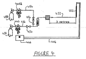
- FIG. 4 is a schematic representation of the test arrangement used in the following Example.
- a lance (402) is connected to a cylinder (438) of oxygen gas at 30 MPa via conduits (432, 436) and valves (434, 440). Ignition of the lance is provided by the electrical ignition system (444, 446).
- a cylinder (450) of compressed carbon dioxide gas is connected by a pressure regulator (452) and a conduit (454) to a second valve (456).
- the firework (402) is operated as described above and may be extinguished in an emergency by shutting off the oxygen supply (i.e. by closing valve (434)) to the firework and, instead, supplying carbon dioxide (i.e. by opening valve (456)) to the firework.
- the lance (402) was 2 m long and consisted of an outer steel tube of circular cross section, having an outside diameter of about 16 mm and a bore of about 14 mm, enclosing a plurality of soft iron wires and aluminium tubing.
- a polyurethane fuse was provided at the outlet end portion of the lance.
- the lance was ignited electrically and gaseous molecular oxygen at a pressure of about 200 kPa to about 400 kPa was passed through the lance at a flow rate of 10 l/min initially, then, after ignition, at 500 l/min.
- Ignition took about 10 s after which the lance burnt successfully with a plume of bright white flame and a shower of bright white and yellow sparks until the whole of the lance had been consumed which took about 2 minutes.
- the height of the plume was about 6m.
Landscapes
- Engineering & Computer Science (AREA)
- Life Sciences & Earth Sciences (AREA)
- Geology (AREA)
- Mining & Mineral Resources (AREA)
- General Engineering & Computer Science (AREA)
- Physics & Mathematics (AREA)
- Environmental & Geological Engineering (AREA)
- Fluid Mechanics (AREA)
- General Life Sciences & Earth Sciences (AREA)
- Geochemistry & Mineralogy (AREA)
- Air Bags (AREA)
- Discharge Heating (AREA)
- Dental Tools And Instruments Or Auxiliary Dental Instruments (AREA)
- Dental Preparations (AREA)
- Waste-Gas Treatment And Other Accessory Devices For Furnaces (AREA)
- Lighters Containing Fuel (AREA)
- Furnace Charging Or Discharging (AREA)
- Manufacture And Refinement Of Metals (AREA)
- Nozzles (AREA)
- Arc Welding In General (AREA)
Abstract
A thermic lance (102) is ignitable using a combustible plastic fuse (120, 122) ignited using electrical means (126). The thermic lance may be used as a firework. Electrical ignition of a thermic lance is more convenient and safer than conventional methods. In addition, when used as a firework, the lance is safer and provides less pollution than conventional fireworks.
Description
- The present invention relates to thermic lances and the use thereof.
- Thermic lances were developed following the Second World War as a means by which gun emplacements, submarine pens and other large concrete structures could be broken up or demolished quickly and conveniently.
- Operation of a thermic lance usually involves feeding gaseous molecular oxygen through a length of steel tube, the tip of which has previously been heated to combustion temperature. The oxygen combines with the iron in the steel of the lance to form a slag that is rich in iron oxides. The slag produced is very hot and very fluid thus enabling the lance to be used as a cutting and/or boring tool. The flow of slag is assisted by the velocity of the gas and the vapours expelled within it.
- The lance is usually packed with steel rods such that the ratio of iron to oxygen is increased thus providing sufficient heat to melt concrete (the melting point of which is between 1800 to 2500°C) and/or ferrous or non ferrous metals. The heat output of a lance may be increased by adding aluminium and/or magnesium to the packing. Smaller lances have been packed with a roll of sheet steel in place of steel rods.
- Examples of thermic lances are disclosed in, for example,
US-A-3570419 (Brandenberger; published 1971),US-A-3738288 (Brandenberger; published 1973) andGB-A-2151530 - A thermic lance is usually ignited by heating the tip of the lance to the combustion temperature using an oxy-acetylene torch. The tip may also be heated to the required temperature by shorting the tip over a car battery. Either way, once heated, oxygen is then fed through the lance promoting fusion at the lance tip. The combustion reaction is self-supporting and will continue until either the flow of oxygen is stopped or all of the fuel from steel has been consumed. The lance itself is obviously consumed during operation.
- The use of an oxy-acetylene torch or a car battery to ignite the lance is not necessarily convenient in all circumstances. In addition, the use of fuel gases with an oxy-acetylene torch is potentially dangerous. The Lance Igniter Tube (or "LIT") process (Australian Thermic Lance Company) has been developed as a safer way to ignite thermic lances. The process involves the use of a Lance Wick and a Lance Igniter Tube. Once lit, the Lance Wick smoulders slowly. The lance is placed over the LIT tube and the smouldering wick is placed in the same position. Oxygen gas is fed through the lance at low pressure and the wick flares into flame and ignites the LIT tube. The lance is moved into the LIT tube and the oxygen gas flow increased to cause a fierce flame which heats up the end of the lance to the point of ignition.
- Ignition of a thermic lance using the LIT process requires two people and, thus, is not convenient if a second person is not available.
- Objectives of preferred embodiments of the present invention therefore include:
- providing a thermic lance that may be ignited more safely and more conveniently by one person; and
- providing a thermic lance that may be ignited from a safe distance, e.g. remotely.
- Conventional fireworks involve the use of dangerous, explosive and toxic materials. For example, the primary explosive in a firework is usually black powder which is a well known mixture of charcoal, sulfur and potassium nitrate in particular proportions. The products from exploding black powder include smoke, pollutant gases such as sulfur dioxide and sodium and potassium ions which can destroy or sicken non-salt tolerant plants. In addition, the colouration in a firework is usually provided by metal chlorates and/or perchlorates which are usually highly toxic.
- A further objective of preferred embodiments of the present invention therefore include providing a safer and more convenient alternative to conventional fireworks.
- The Inventor realised that the shower of "sparks" produced by a thermic lance in use is aesthetically pleasing and, thus, believes a suitably modified thermic lance provides a suitable substitute for certain forms of conventional firework including "fountain" and "gerb" fireworks. However, he also realised that none of the current modes of ignition of conventional thermic lances would be suitable for use with a thermic lance firework as they are not convenient, sufficiently controllable or operable remotely. In addition, the current ignition modes usually involve sources of a fuel gas and, thus, are potentially dangerous.
- The Inventor has discovered that, surprisingly, plastics materials and, in particular, polyurethane, may be used to ignite the tip of a thermic lance. A plastic fuse is ignited using low power electrical means and the ignited fuse itself ignites a thermic lance. In this way, controllable and reliable ignition of a thermic lance may be achieved conveniently by one person from a remote location. The Inventor has also discovered that ignition is sufficiently reliable for the thermic lance to be used as a firework.
- According to a first aspect of the present invention, there is provided a thermic lance comprising an combustible metal outer tube having an oxidant gas inlet end portion and an outlet end portion, said end portions being in gas flow communication along at least one gas flow path,
characterised in that said lance further comprises: - a combustible plastic fuse mounted at the outlet end portion of said outer tube for igniting said lance; and
- an electrical ignition system for igniting said fuse.
- The plastic fuse may be made from any suitable plastics material. The plastic fuse may be made solely or predominately from a plastics material. Suitable plastics materials are those which burn "cleanly", i.e. with little or no emission of toxic fumes, and which burn (in a flow of oxidant gas, particularly molecular oxygen gas) with sufficient heat to ignite the combustible metal of the outer tube or, preferably, the combustible metal of the wires that may be provided within the fuse (see below).
- Suitable plastics materials burn "white hot" in molecular oxygen, e.g. at a temperature of at least 1800°C, usually over 2000°C and typically at about 2500°C. The combustion temperature depends on the rate of flow of the oxidant gas but it is usually no more than 3000°C.
- Examples of suitable plastics materials are selected from the group consisting of polyurethane, polyethylene and nylon although polyurethane is preferred.
- The plastic fuse usually further comprises a plurality of combustible metal wires extending from the fuse into said outer tube. The plastic of the fuse ignites the wires which, in turn, facilitate ignition of the outer tube. The diameter of the wires should be no more than 3 mm, e.g. usually from about 1 mm to about 2 mm.
- The plastic fuse is preferably tubular, typically in the form of a short (e.g. from about 1 cm to about 10 cm) length of flexible plastic tubing, which may be mounted co-axially at the outlet end portion of the outer tube. Adhesive or any other type of suitable fixing may be used to attach the plastic fuse to the outlet end of the outer tube. However, in preferred embodiments, the inner diameter of at least a portion of the tubular plastic fuse is about the same as (or even slightly smaller than if the tubing is resilient) the outer diameter of the outer tube thereby providing a "friction fit" of the plastic fuse over the outlet end portion of the outer tube. No adhesive is then necessary to attach the plastic fuse to the tube.
- The Inventor has discovered that ignition of the thermic lance requires a reduced rate of flow of oxidant gas, at least until ignition is fully established. The reduced flow rate may be provided by careful adjustment of the flow rate of the oxidant gas through the lance. Alternatively, the reduced flow rate may be provided at least in part by at least one first gas flow control aperture provided at the outlet end portion of the lance. The aperture(s) may be provided in the fuse or in the outlet end portion of the outer tube. After the fuse has been consumed, the flow control aperture(s) disappears thereby automatically increasing the flow of oxidant gas through the lance.
- The or at least one aperture may be defined by a wall projecting radially either from the inner surface of a tubular plastic fuse provided over the outlet end portion of the outer tube or from the inner surface of the outlet end of the outer tube itself.
- The electrical ignition system usually comprises:
- an electrical igniter provided at least within ignition range of the fuse;
- means of producing electric current in said igniter;
- electrical connections for providing an electrical circuit between the electrical igniter and said means for producing electric current; and
- a switch for remotely controlling the flow of electric current around said electrical circuit to said igniter.
- The electrical igniter may be provided in contact with the plastic fuse.
- The electrical igniter is preferably a length of NiChrome wire. "NiChrome" is a nickel-chromium alloy with high electrical resistence and an ability to withstand high temperatures. The length of the NiChrome wire is usually from about 10 mm to about 30 mm, preferably about 20 mm. In embodiments in which the plastic fuse is tubular, e.g. a short length of plastic tube, the length of NiChrome wire is usually formed into a loop and provided in the interior of the plastic fuse. On passing a small current, e.g. no more than a few amps such as from about 1 A to about 3 A, through the NiChrome wire, the wire gets very hot, thereby igniting the plastic fuse. An advantage of NiChrome wire is that it does not rust in the atmosphere, even in the presence of atmospheric pollutants.
- The electrical igniter may be an electric match such as those used to ignite conventional fireworks or model rockets. An electric match is about the size of a conventional match head and typically comprises a solid droplet of rapid burning oxidizer/fuel mixture with a very fine wire built in connected to two robust connecting wires. On passing a small current, no more than about 1 A, the electric match instantly ignites with a faint "bang". In embodiments in which the plastic fuse is tubular, e.g. a short length of plastic tube, the electric match may be provided in the interior of the plastic tube.
- The means for producing the electric current is preferably a battery, e.g. a 12 volt battery such as that used in a car.
- The lance may consist simply of the outer tube, the plastic fuse and the electrical ignition system. However, usually, at least one combustible metal elongate insert is enclosed within the outer tube. One purpose of the insert(s) is to increase the amount of fuel present thereby increasing the amount of oxidation products and heat that may be produced by the lance. The insert(s) defines at least one gas flow path within the outer tube providing gas flow communication between the end portions of said outer tube.
- The insert may be in the form of a roll of sheet combustible metal in which case the gas flow path is between layers of the roll. Usually, however, a plurality of combustible metal rods or wires would be packed inside the outer tube in which case the gas flow paths are between each rod or wire. An inner tube of combustible metal having an external diameter that is less than, e.g. about half, the internal diameter of the outer tube may be used as an insert. The thermic lance preferably further comprises:
- an combustible metal inner tube having an oxidant gas inlet end portion and an outlet end portion, said inner tube being provided co-axially within said outer tube with the outlet end portion of the inner tube extending beyond the outlet end portion of the outer tube; and
- a plurality of combustible metal rods, a portion of said plurality being enclosed within the inner tube and the remaining portion being provided between the inner and outer tubes, said rods defining gas flow paths within the outer tube providing gas flow communication between the end portions of said outer tube.
- In such embodiments, the plastic fuse may be mounted only on the outlet end portion of the inner tube. However, the plastic fuse preferably has two parts, a first part mounted on the outlet end portion of the inner tube and a second part mounted on the outlet end portion of the outer tube. The plastic fuse may further comprise a first plurality of combustible metal wires extending from the first part of the fuse into said inner tube and a second plurality of combustible metal wires extending from the second part of the fuse into said outer tube.
- In embodiments of the lance comprising an combustible metal inner tube, there may be at least one further first gas flow control aperture provided at the outlet end portion of the lance. The further aperture may be defined by an integral wall projecting radially either from the inner surface of the outlet end portion of the inner tube or from the inner surface of the first part of the plastic fuse.
- Pressure fluctuations in the source of the oxidant gas can cause fluctuations during the burning of the lance. The thermic lance preferably comprises an integral wall projecting radially from the inner surface of the outer tube at the oxidant gas inlet end portion thereof defining a second gas flow control aperture for controlling the flow of oxidant gas through the outer tube. Such an aperture has the effect of limiting flow rate of oxidant gas through the lance thereby inhibiting fluctuations in the burning of the lance. The size of the aperture is proportional to the size of the lance.
- Such gas flow control apertures have particular application in embodiments in which a plurality of lances are connected to a single source of oxidant gas and used as fireworks. In these embodiments, the fluctuations in oxidant gas pressure may be sufficiently large to extinguish a lance.
- A solid oxidant material may be provided on the surface of the combustible metal at the outlet end portion of the outer tube and, if present, of the inner tube and/or rod(s), etc. to allow the tip of the lance to be kept at about the required combustion temperature. Such a feature may be referred to as a "slow fuse". Suitable solid oxidants include metal nitrate or perchlorate salts.
- Alternatively, the tip of the lance can be kept at about the required combustion temperature by maintaining a "standby" flow rate, just a few l/min (from about 1 l/min to about 10 l/min, e.g. about 5 l/min) of oxidant gas, e.g. molecular oxygen, to the lance.
- If the thermic lance is to be used as a firework, it is often desirable to have different coloured sparks produced therefrom. Lances containing mostly aluminium will preduce a silver/white fountain of sparks, while lances containing mostly iron will produce a shower of yellow sparks.
- Differently coloured sparks may be produced by providing at least one colorant on at least a portion of the surfaces of the combustible metal or by adding the colorant to the flow of oxidant gas to the lance. The colorant preferably comprises metal ions which emit light in the visible part of the electromagnetic spectrum when heated. Different metal ions emit different colours. Suitable metal ions include the ions of alkali metals, alkaline earth metals and certain transition metals. Suitable colorants may be selected from the group consisting of the chloride, chlorate and perchlorate salts of alkali metals such as sodium and potassium; of alkaline earth metals such as barium and strontium; and of certain transition metals such as copper.
- It is possible to control the size of the sparks produced by a thermic lance, particularly lances having aluminium outer tubes, by providing an outer wrap of a combustible material which does not melt, such as paper. Accordingly, lances may further comprise at least one layer of paper enclosing the outer tube. For example, 6 layers of heavy brown Kraft paper appear to retain the combustible metal of the outer tube, particularly aluminium, until it is hot enough to split into very small sparks, e.g. about 1 mm to about 2 mm in diameter or even less.
- The oxidant gas inlet end portion of the outer tube of the lance may be connected by a first conduit to an oxidant gas flow control valve. The flow control valve may, in turn, be connected by a second conduit to a gas regulator provided on a cylinder of compressed oxidant gas. The gas flow control valve may be a normally closed solenoid valve. Accordingly, the thermic lance may further comprise:
- a normally closed solenoid valve for controlling the flow of oxidant gas through the lance;
- a first conduit for providing gas flow communication between said valve and the oxidant gas inlet end portion of the outer tube of said thermic lance;
- means for producing electric current;
- electrical connections for providing an electrical circuit between said solenoid valve and said means for producing electric current; and
- a switch for controlling the flow of electric current around the electrical circuit to each valve.
- Preferably, the oxidant gas flow control valve has means to provide an automatic cut off so that the supply of oxidant gas may be stopped automatically once the thermic lance has been consumed.
- One option is to include a fusable circuit breaker in the electrical connections. The circuit breaker is preferably mounted at the oxidant gas inlet end portion of the outer tube of the lance. Once the lance has burnt down to the circuit breaker, the breaker melts thereby cutting the circuit. The normally closed solenoid valve then closes automatically, shutting off the oxidant gas supply.
- The circuit breaker may be an internally mounted wire loop comprising, for example, strands of copper wire sheathed in PVC insulation. The loop is burned by the burning outer tube and goes "open circuit" which can also be used to shut off the solenoid valve.
- A further option would be to use a spring loaded valve mounted in the gas flow path at the oxygen gas inlet end portion of the outer tube of the lance, said valve being biased in the open position by a fusable detent, i.e. a detent that melts at the temperature that may be produced by the thermic lance, e.g. from about 1000°C to about 2600°C. Again, once the burning outer tube reaches the detent, the detent melts thereby releasing the spring loaded valve to close off the supply of oxidant gas.
- The spring loaded valve may be a "ball-spring" type of check valve mounted so that it points up stream. Such a valve comprises a ball which seals on the end of a cylindrical inlet, pushed by a spring, and will normally only allow reverse flow and not forward flow. The forward flow is allowed by a valve opener, such as a piece of metal, e.g. a thin tube, inside a cylindrical input, which pushes the ball off its sealing face. It is held in place by a detent, e.g. an annulus or a cross-flow pin, made of an easily fusable material. When the oxygen flame reaches the detent, the detent melts allowing the valve opener to move backwards against the flow, allowing the ball, under spring pressure, to seal against the inlet flow.
- It may be necessary to extinguish the lance immediately in the event of an emergency. Therefore, the lance may be connected to a source of a pressurised inert gas such as nitrogen or carbon dioxide via a valve. In the event of an emergency, the oxidant gas supply may be shut off and the inert gas supply turned on. The lance would immediately be extinguished although would remain hot for some time.
- The shape of the cross section of the outer (or inner) tube is not critical to the present invention. The shape is usually circular. However, other polygonal shapes such as triangular, square, pentagonal, etc. may be used as suitable cross sectional shapes.
- Similarly, the dimensions of the outer tube are also not critical to the present invention. The size of the bore of the outer tube is usually about 5 mm to about 30 mm, but is typically no more than 20 mm, e.g. about 14 mm. The thickness of the tube wall is usually from 0.75 mm to about 1.25 mm, e.g. about 1 mm. The length of the outer tube is usually from about 0.5 m to about 3 m, e.g. 2 m.
- Any suitable combustible metal may be used for the outer tube, the wires of the plastic fuse and the insert(s). Suitable combustible metals include metals comprising iron; aluminium; or magnesium. Suitable metals are preferably iron or, more usually, steel such as mild steel (CAS number 7439-89-6) or carbon steel (e.g. about 1% carbon, 0.35 % manganese, the remainder being predominately iron and any impurities); aluminium such as high purity aluminium (CAS number 742-99-05); and magnesium. However, alloys of iron with other metals such as aluminium and/or magnesium may also be used. Better sparks are observed if carbon steel is used in place of mild steel.
- In preferred embodiments, the outer tube is made from iron or steel; a portion of the plurality of inserts is made from iron or steel; the remaining portion of the plurality of inserts is made from aluminium or magnesium; and the wires in the plastic fuse are made from iron or steel. In embodiments having an inner tube as an insert, together with a plurality of rods, the inner tube is usually made from aluminium; and each rod is made from iron or steel. If present, the proportion of aluminium in the lance is usually in the range of about 5 wt % to about 95 wt %.
- The flow of high pressure gas through the outer tube of a thermic lance is known to dislodge inserts provided within the tube. Therefore, the outer tube may be "crimped" or may comprise an S-bend at or near the oxidant inlet end portion thereof to inhibit insert(s) from becoming dislodged and from being ejected out of the outlet end of the outer tube.
- Any suitable oxidant gas may be used. However, the oxidant gas usually at least comprises gaseous molecular oxygen. Thus, the oxidant gas could be air. However, in much preferred embodiments, the oxidant gas is molecular oxygen.
- The operating pressure of the oxidant gas is usually from 100 kPa to about 5 MPa, e.g. from about 200 kPa to about 400 kPa.
- The lance of the present invention may be used as a cutting or a boring tool. However, as the lances produce an aesthetically pleasing spray of small sparks, there is provided, in a second aspect of the present invention, use of a thermic lance according to the first aspect as a firework. The thermic lance can have any of the above mentioned features in any appropriate combination.
- In addition, according to a third aspect of the present invention, there is provided a system of fireworks, said system comprising:
- a source of pressurised oxidant gas;
- a plurality of thermic lances, each lance being as defined in the first aspect;
- an oxidant gas flow control valve for each thermic lance;
- a first conduit for each pairing of a valve and a thermic lance, each first conduit for providing gas flow communication between said valve and the oxidant gas inlet end portion of the outer tube of said thermic lance; and
- a second conduit for providing gas flow communication between said source of pressurised oxidant gas and each valve.
- The lances may be identical or at least some may be different, e.g. have different length, diameter, colour, etc.
- The system preferably further comprising a control system for remotely operating said valves. Where each valve is a normally closed solenoid valve, the control system preferably comprising:
- means for producing electric current;
- electrical connections for providing an electrical circuit between each solenoid valve and said means for producing electric current; and
- a switch for controlling the flow of electric current around each electrical circuit to each valve.
- Where appropriate, the system preferably comprises a single means for producing electric current to operate each electrical igniter. Where appropriate, the same control wires can operate the ignition system current and the control valve system.
- The source of pressurized oxidant gas may be a single cylinder of said gas, e.g. for smaller sized displays. A bank of cylinders of compressed gas, such as a manifolded set or "pack" of cylinders, may be used as the source of pressurised gas, e.g. for medium sized displays. At least one tank of liquefied oxidant gas may be used as the source of pressurised oxidant gas, e.g. for larger (or multiple) displays. In these embodiments, the liquefied oxidant gas is vaporised and the pressure of the gas adjusted to the operating pressure. Obviously, in embodiments where the oxidant gas is gaseous molecular oxygen, the tank(s) would contain liquid oxygen ("LOX").
- Where the source of oxidant gas is one or more cylinders of pressurised gas, the pressure of the stored oxidant gas is usually about 30 MPa. The oxidant gas is fed through a regulator to reduce the pressure before use to an operating pressure in the range from about 100 kPa to about 5 MPa and usually no more than about 1 MPa. Preferred operating pressures include about 700 kPa or from about 200 kPa to about 400 kPa. Where the source of oxidant gas is a tank of liquefied oxidant gas, the liquefied gas is vaporised to produce the oxidant gas and then the pressure is adjusted as required.
- Where the oxidant gas is molecular oxygen, the high pressure part of the system must be made from metals such as copper or brass (which will not combust in the oxygen) and must be "oxygen-clean", i.e. thoroughly degreased.
- The cylinder(s) supply (e.g. at about 30 MPa) feeds a pressure reduction device, e.g. a pressure regulator which reduces the pressure of the oxidant gas to an operating pressure, e.g. from about 100 kPa to about 1 MPa, which allow the safe use of plastic and rubber parts and ordinary pneumatic fittings in the rest of the system.
- In the event of an emergency, the lance may be extinguished simply by shutting off the oxygen supply to the lance. However, if more rapid or complete shutdown is required then an inert gas such as nitrogen or carbon dioxide may also be used. In such embodiments, the system may further comprise:
- a source of pressurised inert gas;
- an inert gas flow control valve;
- a third conduit for providing gas flow communication between said source of pressurised inert gas and said inert gas flow control valve; and wherein said inert gas flow control valve is in gas flow communication with each lance.
- In some embodiments, the flow control valves for the oxidant gas and the inert gas may be integrated within the same valve manifold, for example, the valve manifold of the lance holder if used as a cutting or boring tool. In other embodiments, these flow control valves may be separate and the system may further comprise a fourth conduit for providing gas flow communication between the inert gas flow control valve and the second conduit. In these embodiments, the oxidant gas supply could be shut off and then inert gas allowed to flow through the lance(s) to extinguish the lance(s).
- If coloured fireworks are required, the system may further comprise lances which have a colorant provided on at least a portion of the surfaces of the combustible metal. Alternatively, the system may further comprise:
- at least one source of colorant; and
- means for adding said colorant from said source to a flow of oxidant gas in the second conduit. Each lance may be connected to a different source of colorant thereby producing different coloured flames. Where the colorant is in powdered form, the system may further comprise means for adding powdered colorant to a flow of oxidant gas. Suitable means include powder feed systems employing a sealed powder hopper as used in the metal spraying and flame-spraying industry.
- Each lance in the system may have any of the above mentioned features described in respect of the first aspect in any appropriate combination.
- According to a fourth aspect of the present invention, there is provided a method of using at least one thermic lance according to the first aspect as a firework, said method comprising:
- passing pressurised oxidant gas at an "ignition" flow rate through said thermal lance from the oxidant gas inlet end portion of the outer tube to the outlet end thereof;
- igniting said plastic fuse using said electrical ignition system;
- after ignition, maintaining the flow of pressurised oxidant gas through said lance at a "standby" flow rate until said firework is required; and then
- when required, increasing the flow of pressurised oxidant gas from said "standby" flow rate to a "display" flow rate.
- The "ignition" flow rate is preferably from about 1 l/min to about 10 l/min, e.g. about 5 l/min. The "standby" flow rate is preferably from about 1 l/min to about 10 l/min, e.g. about 5 l/min. The "standby" flow rate is usually just sufficient to maintain the combustion temperature at the tip of the lance and, thus, is usually no less than and may be the same as the "ignition" flow rate. Minimal amounts of sparks are emitted using a "standby" flow rate. The "display" flow rate is usually from about 10 1/min to about 1000 1/min, e.g. from about 200 to about 600 1/min, depending on the effect to be achieved and the size of the lance.
- The flow rate may be increased from the "standby" flow rate to the "display" flow rate shortly after ignition if the firework is required straight away or may be increased some time after ignition if the firework is not required immediately but would be required to spring to life in a moment. The "standby" flow rate is usually the same as the "ignition" flow rate".
- The height to which the sparks are ejected from the lance is dependent to a certain extent on the "display" flow rate of oxidant gas. Thus, a higher "display" flow rate generally results in a greater height to which the sparks are ejected.
- High "display" flow rate of oxidant gas achieves a "fountain" effect from the lance. For example, a flow rate of 500 l/min in a thermic lance having a bore of 14 mm ejects sparks at least 5 m into the air.
- Conversely, low "display" flow rate of oxidant gas can create a "waterfall" effect where a downward flow of sparks is created even if the lance is pointing upwards. A low "display" flow rate is, for example, from 30 l/min to 150 l/min, e.g. 100 l/min.
- Sidewards or downwards orientation is obviously also possible. If a lance is operated on a hard surface, the falling molten droplets can be further divided into smaller sparks when they impact the surface, thereby providing a further desirable aesthetic effect.
- Rotating spark-fountains such as Catherine Wheels, Revolving Suns or Pin Wheels can be created by employing vertically rotating fountains using a rotating joint to the provide the oxidant gas. Horizontally rotating fountains such as Carousels or "girandolas" can also be achieved in this way. The tips of rapidly rotating lances are moving very fast which can provide enhanced long distance spark projection. Further effects can be achieved with rotating spark-fountains by programming the oxidant gas pressure to pulse on and off during the rotation.
- Pulsing the oxidant gas pressure can also be employed to synchronise fountains of sparks with musical accompaniment in the manner of 'son-et-lumiere' firework displays. There is also provided apparatus comprising:
- at least one thermic lance;
- a source of pressurised oxidant gas;
- an oxidant gas flow control valve for the or each thermic lance;
- a first conduit for the or each pairing of a valve and a thermic lance, the or each_ first conduit for providing gas flow communication between said valve and the oxidant gas inlet end portion of said thermic lance;
- a second conduit for providing gas flow communication between said source of pressurised oxidant gas and the or each valve;
- a source of pressurised inert gas;
- an inert gas flow control valve;
- a third conduit for providing gas flow communication between said source of pressurised inert gas and said inert gas flow control valve; and wherein said inert gas flow control valve is in fluid flow communication with the or each lance.
- The thermic lance(s) may be a conventional thermic lance, i.e. not have combustible plastic fuse. Alternatively, the thermic lance(s) may be a lance according to the first aspect of the present invention. In embodiments involving more than one lance, each lance may be either a conventional lance or a lance according to the first aspect of the present invention. Alternatively, a mixture of conventional and present lances may be used. The lance(s) may have any or all of the features of the lances of the first aspect of the present invention defined above in any appropriate combination.
- The or each lance may be used as a cutting or boring tool or as a firework. In embodiments in which the apparatus has only one lance, the lance would usually be used as a cutting or boring tool. In embodiments in the apparatus has a plurality of lances, the apparatus would usually be used as a firework system.
- The present invention will now be described by way of example only and with reference to the accompanying figures in which:
- FIGURE 1 is a partial cross sectional representation of a side view of a thermic lance according to the present invention;
- FIGURE 2 is a cross sectional representation through line A-A of the thermic lance depicted in Figure 1;
- FIGURE 3 is a schematic representation of one possible arrangement of a system fireworks according to the present invention; and
- FIGURE 4 is a schematic representation of the arrangement used in the Example to test the lance as a firework.
- Referring to Figures 1 and 2, a thermic lance (102) has an outer tube (104) made from iron or steel having an oxygen gas inlet end portion (106) and an outlet end portion (108). The outer tube (104) is of circular cross section and has an outside diameter of about 16 mm, a bore of about 14 mm and a length of about 2 m.
- The lance (102) has an inner tube (110) provided co-axially within the outer tube (104). The inner tube (110) has an oxygen gas inlet end portion (112) and an outlet end portion (114) extending beyond the outlet end portion (108) of the outer tube (104). The inner tube is made from aluminium.
- The lance- (102) has a plurality rods (116) enclosed within the outer tube (104). A portion of the plurality is enclosed within the inner tube (110) and the remainder of the plurality is packed between the inner tube (114) and the outer tube (104). The rods (116) are made from iron or steel and define a plurality of gas flow paths (118) providing gas flow communication between the oxygen gas inlet end portion (106) and the outlet end portion (108) of the outer tube (104).
- A polyurethane fuse (120, 122) is mounted on the outlet of the lance (102). The fuse (120, 122) is in two parts; a first part (120) mounted on the outlet end portion (114) of the inner tube (110) and a second part (122) mounted on the outlet end portion (118) of the outer tube (104). Each part (120, 122) is a length of flexible polyurethane tubing. The first part (120) has an internal diameter of no more than the external diameter of the inner tube (110) to provide a friction fit with the inner tube (110). The second part (122) has an internal diameter of no more than the external diameter of the outer tube (104) to provide a friction fit with the outer tube (104).
- A plurality of iron or steel fuse wires (124) are provided within the parts (120, 122) of the fuse and extend into the inner (110) and outer (104) tubes. The diameter of the fuse wires (124) is no more than 2 mm.
- A loop (126) of NiChrome wire is provided in the first part (120) of the polyurethane fuse (120, 122). The loop (126) is part of an electrical ignition system (not shown) for igniting the polyurethane fuse (120, 122).
- The lance (102) has a first gas flow control aperture (128) provided in the outlet end portion (114) of the inner tube (110) and a second gas flow control aperture (130) in the oxygen gas inlet end portion (106) of the outer tube (104).
- The lance (102) also has a "crimped" portion (132) near the oxygen gas inlet end portion (106) of the outer tube (104) of the lance (102) which grips the internal components (110, 116) of the lance (102) to prevent them from being ejected out of the lance (102) during use.
- The thermic lance (102) is ignited by applying an electric current of about 2 A using the electrical ignition system (not shown) through the loop (126) of NiChrome wire while oxygen gas is passed through the lance (102) at a low flow rate of about 5 1/min. The loop (126) becomes hot and ignites the first part (120) of the polyurethane fuse (120, 122).
- The polyurethane fuse burns "white hot" in oxygen, i.e. it burns at a sufficiently high temperature, e.g. about 2000°C, to ignite the iron fuse wires (124). The combination of the ignited fuse wires (124) and burning first part (120) of the polyurethane fuse (120, 122) in the oxygen flow is sufficient to ignite the outlet end portion (114) of the inner tube (110).
- The second part (122) of the fuse (120, 122) and the remaining iron fuse wires (124) are ignited by the heat from the burning first part (120) of the fuse and from the iron that is already_ignited._ There is now sufficient heat to ignite the iron in the outlet end portion (108) of the outer tube (104) of the lance (102) and the ends of the rods (116) in the oxygen gas flow.
- The flow of oxygen through the lance (102) can be maintained at a "standby" flow rate (e.g. about 5 l/min) until the lance is required for use, e.g. as a thermic lance for cutting or boring purposes or as a firework, at which point the oxygen flow rate can be increased to an operating or "display" flow rate from about 10 l/min to about 1000 l/min, e.g. about 100 l/min, depending upon lance size and the degree of spark projection required.
- Figure 3 represents schematically how four lances (302a, 302b, 302c, 302d) as depicted in Figures 1 and 2 might be connected for use as a system of fireworks.
- The first lance (302a) is connected via a first gas conduit (332a) to a normally closed solenoid valve (334a) which, in turn, is connected via a second gas conduit (336) to a source (338) of high pressure oxygen gas via a pressure regulator (340). An example of a suitable source is a cylinder (338) of compressed oxygen gas at a pressure of about 30 MPa.
- The outlet end portion of the lance (302a) is connected to a polyurethane fuse (320a) which in turn is connected to an electrical igniter (342a). The electrical igniter (342a) and the solenoid valve (334a) are connected by the same circuit (344) to a switch array (346) (or a computer operated array of relays) powered by a means (348) of producing electric current which, in this case, is a battery.
- The electrical igniter (342a) may be on a separate circuit from the solenoid valve (334a) and, thus, the igniter (342a) and the valve (334a) may be independently controllable.
- Each of the remaining lances (302b, 302c, 302d) is connected in the same way as the first lance (302a).
- In use, oxygen gas flows from the source (338) through the regulator (340) where the pressure is reduced from about 30 MPa to about 700kPa to the solenoid valves (334a, 334b, 334c, 334d).
- When a particular lance is required, electrical current is passed through the relevant part of the circuitry (344) to open the respective valve and to ignite the electrical igniter thereby igniting the lance itself. Once lit, the lance may be used as a firework simply by increasing the flow of oxygen through the lance (e.g. by opening the solenoid valve further).
- A firework display may be created by the sequential opening and closing of the solenoid valves or otherwise varying oxidant gas flow rates in particular orders to create aesthetically pleasing patterns and effects.
- Figure 4 is a schematic representation of the test arrangement used in the following Example. A lance (402) is connected to a cylinder (438) of oxygen gas at 30 MPa via conduits (432, 436) and valves (434, 440). Ignition of the lance is provided by the electrical ignition system (444, 446). A cylinder (450) of compressed carbon dioxide gas is connected by a pressure regulator (452) and a conduit (454) to a second valve (456).
- The firework (402) is operated as described above and may be extinguished in an emergency by shutting off the oxygen supply (i.e. by closing valve (434)) to the firework and, instead, supplying carbon dioxide (i.e. by opening valve (456)) to the firework.
- A firework system was set up as depicted in Figure 4. The lance (402) was 2 m long and consisted of an outer steel tube of circular cross section, having an outside diameter of about 16 mm and a bore of about 14 mm, enclosing a plurality of soft iron wires and aluminium tubing. A polyurethane fuse was provided at the outlet end portion of the lance.
- The lance was ignited electrically and gaseous molecular oxygen at a pressure of about 200 kPa to about 400 kPa was passed through the lance at a flow rate of 10 l/min initially, then, after ignition, at 500 l/min.
- Ignition took about 10 s after which the lance burnt successfully with a plume of bright white flame and a shower of bright white and yellow sparks until the whole of the lance had been consumed which took about 2 minutes. The height of the plume was about 6m.
- Advantages of preferred embodiments the present invention include:
- Safer and more convenient ignition of thermic lances;
- Reliable remote ignition of thermic lances;
- Safer to make, transport and store than conventional fireworks;
- Safer to use than conventional fireworks as the firework may be extinguished by shutting off the oxygen supply;
- Less toxic than conventional fireworks;
- Less expensive than conventional fireworks; and
- Less harmful to the environment than conventional fireworks.
- Throughout the specification, the term "means" in the context of means for carrying out a function, is intended to refer to at least one device adapted and/or constructed to carry out that function.
- It will be appreciated that the invention is not restricted to the details described above with reference to the preferred embodiments but that numerous modifications and variations can be made without departing from the spirit or scope of the invention as defined by the following claims.
Claims (32)
- A thermic lance (102) comprising an combustible metal outer tube (104) having an oxidant gas inlet end portion (106) and an outlet end portion (108), said end portions being in gas flow communication along at least one gas flow path (118),
characterised in that said lance (102) further comprises:a combustible plastic fuse (120, 122) mounted at the outlet end portion (106) of said outer tube for igniting said lance (102); andan electrical ignition system (126) for igniting said fuse (120, 122). - A thermic lance as claimed in Claim 1 wherein the plastic fuse further comprises a plurality of combustible metal wires (124) extending from the fuse into said outer tube.
- A thermic lance as claimed in Claim 1 or Claim 2 wherein the electrical ignition system comprises:an electrical igniter (126) provided at least within ignition range of the fuse;means of producing electric current in said igniter;electrical connections for providing an electrical circuit between the electrical igniter and said means for producing electric current; anda switch for remotely controlling the flow of electric current around said electrical circuit to said igniter.
- A thermic lance as claimed in Claim 3 wherein the electrical igniter is a length (126) of NiChrome wire.
- A thermic lance as claimed in Claim 3 wherein the electrical igniter is an electric match.
- A thermic lance as claimed in any of the preceding claims wherein the plastic fuse is tubular and is mounted co-axially at the outlet end portion of said outer tube.
- A thermic lance as claimed in Claim 6 further comprising at least one first gas flow control aperture (128) provided at the outlet end of the outer tube or in the fuse for controlling gas flow through the fuse.
- A thermic lance as claimed in any of the preceding claims wherein the plastic fuse is made from a plastics material selected from the group consisting of polyurethane, polyethylene and nylon.
- A thermic lance as claimed in any of the preceding claims further comprising:an combustible metal inner tube (110) having an oxidant gas inlet end portion (112) and an outlet end portion (114), said inner tube being provided co-axially within said outer tube with the outlet end portion of the inner tube extending beyond the outlet end portion of the outer tube; anda plurality of combustible metal rods (116), a portion of said plurality being enclosed within the inner tube (110) and the remaining portion being provided between the inner (110) and outer (104) tubes, said rods (116) defining gas flow paths (118) within the outer tube providing gas flow communication between the end portions of said outer tube.
- A thermic lance as claimed in Claim 9 wherein the plastic fuse has two parts, a first part (120) mounted on the outlet end portion of the inner tube and a second part (122) mounted on the outlet end portion of the outer tube.
- A thermic lance as claimed in Claim 10 wherein the plastic fuse further comprises a first plurality of combustible metal wires (124) extending from the first part of the fuse into said inner tube and a second plurality of combustible metal wires (124) extending from the second part of the fuse into said outer tube.
- A thermic lance as claimed in any of the preceding claims further comprising an integral wall projecting radially from the inner surface of the outer tube at the oxidant gas inlet end portion thereof defining a second gas flow control aperture (130) for controlling the flow of oxidant gas through the outer tube.
- A thermic lance as claimed in any of the preceding claims further comprising at least one colorant provided on at least a portion of the surfaces of the combustible metal.
- A thermic lance as claimed in any of the preceding claims further comprising at least one layer of paper enclosing the outer tube.
- A thermic lance as claimed in any of the preceding claims further comprising:a normally closed solenoid valve (334) for controlling the flow of oxidant gas through the lance;a first conduit (332) for providing gas flow communication between said valve and the oxidant gas inlet end portion of the outer tube of said thermic lance;means (348) for producing electric current;electrical connections (344) for providing an electrical circuit between said solenoid valve and said means for producing electric current; anda switch (346) for controlling the flow of electric current around the electrical circuit to each valve.
- A thermic lance as claimed in Claim 15 wherein the electrical connections include a fusable circuit breaker mounted at the oxidant gas inlet end portion of the outer tube of the lance.
- A thermic lance as claimed in any of the preceding claims further comprising a spring loaded valve mounted in the gas flow path at the oxygen gas inlet end portion of the outer tube of the lance, said valve being biased in the open position by a fusable detent.
- A thermic lance as claimed in any of the preceding claims wherein a solid oxidant material is provided on at least a portion of the outlet end portion of the lance.
- A system of fireworks, said system comprising:a source (338, 340) of pressurised oxidant gas;a plurality of thermic lances (102), each lance being as defined in Claim 1;an oxidant gas flow control valve (334) for each thermic lance;a first conduit (332) for each pairing of a valve and a thermic lance, each first conduit for providing gas flow communication between said valve and the oxidant gas inlet end portion of the outer tube of said thermic lance; anda second conduit (336) for providing gas flow communication between said source of pressurised oxidant gas and each valve.
- A system as claimed in Claim 19 further comprising a control system (346) for remotely operating said valves.
- A system as claimed in Claim 20 wherein each valve (334) is a normally closed solenoid valve, said control system comprising:means (348) for producing electric current;electrical connections (344) for providing an electrical circuit between each solenoid valve and said means for producing electric current; anda switch (346) for controlling the flow of electric current around each electrical circuit to each valve.
- A system as claimed in any of Claims 19 to 21 wherein each thermic lance is as defined in Claim 3, said system comprising a single means (348) for producing electric current to operate each electrical igniter.
- A system as claimed in any of Claims 19 to 22 further comprising:a source (450, 452) of pressurised inert gas;an inert gas flow control valve (456);a third conduit (454) for providing gas flow communication between said source of pressurised inert gas and said inert gas flow control valve; and wherein said inert gas flow control valve is in gas flow communication with each lance.
- A system as claimed in any of Claims 19 to 23 further comprising:at least one source of colorant;means for adding said colorant from said source to a flow of oxidant gas in the second conduit.
- A system as claimed in any of Claims 19 to 24 wherein each lance is as defined in any of Claims 2 to 18.
- Use of a thermic lance (102) as defined in Claim 1 as a firework.
- Use as claimed in Claim 26 wherein the thermic lance is as defined in any of Claims 2 to 18.
- A method of using at least one thermic lance (102) as defined in Claim 1 as a firework, said method comprising:passing pressurised oxidant gas at an "ignition" flow rate through said thermal lance (102) from the oxidant gas inlet end portion (106) of the outer tube (104) to the outlet end portion (108) thereof;igniting said plastic fuse (120, 122) using said electrical ignition system (126);after ignition, maintaining the flow of pressurised oxidant gas through said lance at a "standby" flow rate until said firework is required; and thenwhen required, increasing the flow of pressurised oxidant gas from said "standby" flow rate to a "display" flow rate.
- A method as claimed in Claim 28 wherein said "ignition" flow rate is from about 1 l/min to about 10 l/min.
- A method as claimed in Claim 28 or Claim 29 wherein said "standby" flow rate is from about 1 l/min to about 10 l/min.
- A method as claimed in any of Claims 28 to 30 wherein said "display" flow rate is from about 10 1/min to about 1000 1/min.
- Apparatus comprising
at least one thermic lance;
a source of pressurised oxidant gas;
an oxidant gas flow control valve for the or each thermic lance;
a first conduit for the or each pairing of a valve and a thermic lance, the or each first conduit for providing gas flow communication between said valve and the oxidant gas inlet end portion of said thermic lance;
a second conduit for providing gas flow communication between said source of pressurised oxidant gas and the or each valve;
characterised in that said apparatus further comprises:a source of pressurised inert gas;an inert gas flow control valve;a third conduit for providing gas flow communication between said source of pressurised inert gas and said inert gas flow control valve; andwherein said inert gas flow control valve is in fluid flow communication with the or each lance.
Priority Applications (17)
| Application Number | Priority Date | Filing Date | Title |
|---|---|---|---|
| EP06252055A EP1847678A1 (en) | 2006-04-13 | 2006-04-13 | A thermic lance |
| US11/732,973 US7691321B2 (en) | 2006-04-13 | 2007-04-05 | Thermic lance |
| MX2007004207A MX2007004207A (en) | 2006-04-13 | 2007-04-09 | A thermic lance . |
| SG200702605-7A SG136889A1 (en) | 2006-04-13 | 2007-04-09 | A thermic lance |
| BRPI0702012-0A BRPI0702012A (en) | 2006-04-13 | 2007-04-10 | use of a thermal lance, firework system, method of using at least one thermal lance as a firework, and thermal lance |
| CA2584996A CA2584996C (en) | 2006-04-13 | 2007-04-10 | A thermic lance |
| ZA200702931A ZA200702931B (en) | 2006-04-13 | 2007-04-10 | A thermic lance |
| AT07251551T ATE423266T1 (en) | 2006-04-13 | 2007-04-11 | WELDING TORCH |
| EP07251551A EP1845231B1 (en) | 2006-04-13 | 2007-04-11 | A thermic lance |
| PT07251551T PT1845231E (en) | 2006-04-13 | 2007-04-11 | A thermic lance |
| DE602007000550T DE602007000550D1 (en) | 2006-04-13 | 2007-04-11 | welding torch |
| ES07251551T ES2321238T3 (en) | 2006-04-13 | 2007-04-11 | A THERMAL LAUNCH |
| PL07251551T PL1845231T3 (en) | 2006-04-13 | 2007-04-11 | A thermic lance |
| DK07251551T DK1845231T3 (en) | 2006-04-13 | 2007-04-11 | Thermal lance |
| JP2007105204A JP2007315741A (en) | 2006-04-13 | 2007-04-12 | Thermic lance |
| CNA2007100961352A CN101055162A (en) | 2006-04-13 | 2007-04-13 | Thermal spray gun |
| HK08101214.0A HK1110640B (en) | 2006-04-13 | 2008-01-31 | A thermic lance |
Applications Claiming Priority (1)
| Application Number | Priority Date | Filing Date | Title |
|---|---|---|---|
| EP06252055A EP1847678A1 (en) | 2006-04-13 | 2006-04-13 | A thermic lance |
Publications (1)
| Publication Number | Publication Date |
|---|---|
| EP1847678A1 true EP1847678A1 (en) | 2007-10-24 |
Family
ID=36972913
Family Applications (2)
| Application Number | Title | Priority Date | Filing Date |
|---|---|---|---|
| EP06252055A Withdrawn EP1847678A1 (en) | 2006-04-13 | 2006-04-13 | A thermic lance |
| EP07251551A Active EP1845231B1 (en) | 2006-04-13 | 2007-04-11 | A thermic lance |
Family Applications After (1)
| Application Number | Title | Priority Date | Filing Date |
|---|---|---|---|
| EP07251551A Active EP1845231B1 (en) | 2006-04-13 | 2007-04-11 | A thermic lance |
Country Status (15)
| Country | Link |
|---|---|
| US (1) | US7691321B2 (en) |
| EP (2) | EP1847678A1 (en) |
| JP (1) | JP2007315741A (en) |
| CN (1) | CN101055162A (en) |
| AT (1) | ATE423266T1 (en) |
| BR (1) | BRPI0702012A (en) |
| CA (1) | CA2584996C (en) |
| DE (1) | DE602007000550D1 (en) |
| DK (1) | DK1845231T3 (en) |
| ES (1) | ES2321238T3 (en) |
| MX (1) | MX2007004207A (en) |
| PL (1) | PL1845231T3 (en) |
| PT (1) | PT1845231E (en) |
| SG (1) | SG136889A1 (en) |
| ZA (1) | ZA200702931B (en) |
Families Citing this family (9)
| Publication number | Priority date | Publication date | Assignee | Title |
|---|---|---|---|---|
| US9345853B2 (en) | 2010-12-10 | 2016-05-24 | Teknor Apex Company | Tube assembly and method for making the assembly |
| FR2988901B1 (en) * | 2012-04-03 | 2015-01-30 | Renault Sa | DEVICE FOR ELECTRICAL SAFETY CUT |
| US8920711B2 (en) | 2012-07-20 | 2014-12-30 | Specialty Minerals (Michigan) Inc. | Lance for wire feeding |
| CL2014000034A1 (en) * | 2014-01-07 | 2014-10-03 | Trefimet S A | Thermal lance for drilling and / or fusion cutting any material, comprises at least 4 tubular profiles, one outer and three inner, and more than 17 cavities inside the lance, at least 2 of the 4 tubular profiles have different cross sections and the profiles are located contiguously; and use of the spear. |
| CN108500418A (en) * | 2018-05-18 | 2018-09-07 | 福建泉城特种装备科技有限公司 | A kind of portable cutter and its use cutting method |
| US11150023B2 (en) * | 2019-04-05 | 2021-10-19 | Michael F. Harasym | Wind turbine lance ignition system |
| CN110529685B (en) * | 2019-09-11 | 2021-11-09 | 中船动力研究院有限公司 | Double-wall pipe connecting device |
| CN111156542A (en) * | 2020-01-21 | 2020-05-15 | 广州市南沙区卓新金属制品厂 | Detachable igniter |
| CN114378402A (en) * | 2021-12-07 | 2022-04-22 | 广西金川有色金属有限公司 | High-temperature cutting device using oxygen for combustion supporting and using method thereof |
Citations (9)
| Publication number | Priority date | Publication date | Assignee | Title |
|---|---|---|---|---|
| US1761094A (en) * | 1926-03-19 | 1930-06-03 | Jr James H Shunk | Fireworks construction |
| US3090856A (en) * | 1963-05-21 | Gas torch lighter | ||
| FR1502040A (en) * | 1966-10-05 | 1967-11-18 | Ruggieri Ets | Pyrotechnic light fountain |
| US3588303A (en) * | 1968-03-01 | 1971-06-28 | August Karrer | Apparatus for holding thermal lances |
| GB1343023A (en) * | 1971-04-19 | 1974-01-10 | British Oxygen Co Ltd | Termic lance holders |
| US4055332A (en) * | 1975-11-03 | 1977-10-25 | Aai Corporation | Cutting torch arrangement |
| US4391209A (en) * | 1981-06-16 | 1983-07-05 | Arcair Company | Exothermic cutting electrode |
| GB2151530A (en) * | 1983-12-20 | 1985-07-24 | Hong Kong The University Of | Thermic lance and dual-stage combustion system |
| US4985610A (en) * | 1988-05-26 | 1991-01-15 | E. I. Du Pont De Nemours And Company | Cutting torch |
Family Cites Families (21)
| Publication number | Priority date | Publication date | Assignee | Title |
|---|---|---|---|---|
| US340747A (en) * | 1886-04-27 | Pyrotechnic match | ||
| GB1093336A (en) | 1966-02-21 | 1967-11-29 | Silberhuette Pyrotechnik Veb | Improvements in and relating to pyrotechnic hand torches |
| CH484715A (en) | 1968-01-03 | 1970-01-31 | Brandenberger Ernst | Gas burning lance for creating openings in concrete, stone, building walls and the like. |
| CH556724A (en) | 1971-02-05 | 1974-12-13 | Brandenberger Ernst | OXYGEN LENS FOR CREATING OPENINGS IN CONCRETE, ROCK, BUILDING WALLS AND THE LIKE. |
| DE2531918C3 (en) * | 1975-07-17 | 1979-03-01 | Rudolf 5882 Meinerzhagen Kallenbach | Method and device for thermochemical drilling and separating rock or the like, flux and device for mixing the flux content |
| JPS5334909A (en) * | 1976-09-13 | 1978-03-31 | Hiroyuki Ezaki | Children*s fire work |
| EP0007289A1 (en) | 1978-07-07 | 1980-01-23 | Battelle Memorial Institute | Ignition device for oxygen cutting lances |
| JPS6029621B2 (en) * | 1978-09-02 | 1985-07-11 | 押尾産業株式会社 | Method for manufacturing a bag with a back seal |
| JPS5918399A (en) * | 1982-07-23 | 1984-01-30 | 細谷 一夫 | Water-surface star mine |
| JPS60185898U (en) * | 1984-05-18 | 1985-12-09 | 中川 茂 | Shaft for toy fireworks |
| JPS63197998U (en) * | 1987-01-14 | 1988-12-20 | ||
| DE3809636C1 (en) * | 1988-03-22 | 1989-05-24 | Norabel Ab, Nora, Se | |
| US5622672A (en) * | 1995-03-24 | 1997-04-22 | Alloy Surfaces Co. | Ignition of thermal lance and means and method for use therewith and therefor |
| US5710390A (en) * | 1995-08-01 | 1998-01-20 | Ofca; William W. | Shock tube initiating system for display fireworks |
| US5580515A (en) * | 1995-08-22 | 1996-12-03 | Petrovich; Paul A. | Chemical igniter for an exothermic cutting lance |
| US5993201A (en) * | 1997-09-29 | 1999-11-30 | Eastman Kodak Company | Enclosed frictionally ignited photographic flash lamp |
| JP2000074599A (en) * | 1998-08-27 | 2000-03-14 | Gunma Kako Seizosho:Kk | Color fire generator for set fireworks |
| JP2000191391A (en) * | 1998-10-22 | 2000-07-11 | Nippon Kayaku Co Ltd | Pyrotechnic composition and its production |
| JP2002012491A (en) * | 2000-06-28 | 2002-01-15 | National Institute Of Advanced Industrial & Technology | Pyrotechnic composition and method for producing the same |
| EP1362213B1 (en) * | 2001-04-12 | 2004-12-15 | Bang & Clean GmbH | Method and apparatus for cleaning combustion devices |
| US6530327B2 (en) * | 2001-04-23 | 2003-03-11 | Dmd Systems, Llc | Method and apparatus for burning pyrotechnic compositions |
-
2006
- 2006-04-13 EP EP06252055A patent/EP1847678A1/en not_active Withdrawn
-
2007
- 2007-04-05 US US11/732,973 patent/US7691321B2/en not_active Expired - Fee Related
- 2007-04-09 SG SG200702605-7A patent/SG136889A1/en unknown
- 2007-04-09 MX MX2007004207A patent/MX2007004207A/en active IP Right Grant
- 2007-04-10 BR BRPI0702012-0A patent/BRPI0702012A/en not_active IP Right Cessation
- 2007-04-10 CA CA2584996A patent/CA2584996C/en not_active Expired - Fee Related
- 2007-04-10 ZA ZA200702931A patent/ZA200702931B/en unknown
- 2007-04-11 PT PT07251551T patent/PT1845231E/en unknown
- 2007-04-11 DE DE602007000550T patent/DE602007000550D1/en active Active
- 2007-04-11 DK DK07251551T patent/DK1845231T3/en active
- 2007-04-11 PL PL07251551T patent/PL1845231T3/en unknown
- 2007-04-11 AT AT07251551T patent/ATE423266T1/en not_active IP Right Cessation
- 2007-04-11 ES ES07251551T patent/ES2321238T3/en active Active
- 2007-04-11 EP EP07251551A patent/EP1845231B1/en active Active
- 2007-04-12 JP JP2007105204A patent/JP2007315741A/en not_active Ceased
- 2007-04-13 CN CNA2007100961352A patent/CN101055162A/en active Pending
Patent Citations (9)
| Publication number | Priority date | Publication date | Assignee | Title |
|---|---|---|---|---|
| US3090856A (en) * | 1963-05-21 | Gas torch lighter | ||
| US1761094A (en) * | 1926-03-19 | 1930-06-03 | Jr James H Shunk | Fireworks construction |
| FR1502040A (en) * | 1966-10-05 | 1967-11-18 | Ruggieri Ets | Pyrotechnic light fountain |
| US3588303A (en) * | 1968-03-01 | 1971-06-28 | August Karrer | Apparatus for holding thermal lances |
| GB1343023A (en) * | 1971-04-19 | 1974-01-10 | British Oxygen Co Ltd | Termic lance holders |
| US4055332A (en) * | 1975-11-03 | 1977-10-25 | Aai Corporation | Cutting torch arrangement |
| US4391209A (en) * | 1981-06-16 | 1983-07-05 | Arcair Company | Exothermic cutting electrode |
| GB2151530A (en) * | 1983-12-20 | 1985-07-24 | Hong Kong The University Of | Thermic lance and dual-stage combustion system |
| US4985610A (en) * | 1988-05-26 | 1991-01-15 | E. I. Du Pont De Nemours And Company | Cutting torch |
Also Published As
| Publication number | Publication date |
|---|---|
| US7691321B2 (en) | 2010-04-06 |
| PT1845231E (en) | 2009-03-24 |
| BRPI0702012A (en) | 2007-11-27 |
| DE602007000550D1 (en) | 2009-04-02 |
| JP2007315741A (en) | 2007-12-06 |
| US20070290417A1 (en) | 2007-12-20 |
| CN101055162A (en) | 2007-10-17 |
| ZA200702931B (en) | 2009-06-24 |
| CA2584996A1 (en) | 2007-10-13 |
| PL1845231T3 (en) | 2009-07-31 |
| DK1845231T3 (en) | 2009-06-15 |
| HK1110640A1 (en) | 2008-07-18 |
| EP1845231A2 (en) | 2007-10-17 |
| ATE423266T1 (en) | 2009-03-15 |
| SG136889A1 (en) | 2007-11-29 |
| ES2321238T3 (en) | 2009-06-03 |
| CA2584996C (en) | 2010-07-27 |
| MX2007004207A (en) | 2008-12-01 |
| EP1845231A3 (en) | 2007-11-14 |
| EP1845231B1 (en) | 2009-02-18 |
Similar Documents
| Publication | Publication Date | Title |
|---|---|---|
| EP1845231B1 (en) | A thermic lance | |
| US5783768A (en) | Fire starting flare | |
| JP6105131B2 (en) | Hydrogen torch | |
| MY152876A (en) | Cartridge munition, particularly one of medium caliber | |
| FI124635B (en) | Low-energy fireplace heater | |
| US5622672A (en) | Ignition of thermal lance and means and method for use therewith and therefor | |
| WO2005094413A3 (en) | Linear incendiary strand and method for prescribed fire ignition | |
| JP2004508182A (en) | Gas generator | |
| HK1110640B (en) | A thermic lance | |
| NZ202201A (en) | Underwater thermic lance:both ends sealed prior to ignition | |
| US4050680A (en) | Cutting torch arrangement | |
| US3734476A (en) | Cutting torch | |
| CN207850204U (en) | A kind of explosive decomposer ammunition | |
| WO2004020044A3 (en) | Fire extinguishing training exercise system | |
| US4055332A (en) | Cutting torch arrangement | |
| US4371771A (en) | Cutting torch and method | |
| CN1298960C (en) | Igniter for oxygen lance for thermal cutting, drilling ETC | |
| US3741135A (en) | Cutting torch | |
| EP4158266A1 (en) | Method and apparatus for hot or cold cleaning combustion slag by means of an explosive shock wave | |
| US232443A (en) | Egbert blagklidge | |
| Richard | GROUND FIREWORKS | |
| NO177162B (en) | Method and apparatus for igniting gases in a flame tower | |
| US1057420A (en) | Gas-gun. | |
| SE527975C2 (en) | Pyrotechnic device for clearing landmines and unexploded ammunition has pyrotechnic charge formed by exothermic and oxygen generating charges activated separately | |
| JPS60115777A (en) | Weld-cutting and drilling method of concrete structure |
Legal Events
| Date | Code | Title | Description |
|---|---|---|---|
| PUAI | Public reference made under article 153(3) epc to a published international application that has entered the european phase |
Free format text: ORIGINAL CODE: 0009012 |
|
| AK | Designated contracting states |
Kind code of ref document: A1 Designated state(s): AT BE BG CH CY CZ DE DK EE ES FI FR GB GR HU IE IS IT LI LT LU LV MC NL PL PT RO SE SI SK TR |
|
| AX | Request for extension of the european patent |
Extension state: AL BA HR MK YU |
|
| AKX | Designation fees paid | ||
| STAA | Information on the status of an ep patent application or granted ep patent |
Free format text: STATUS: THE APPLICATION IS DEEMED TO BE WITHDRAWN |
|
| 18D | Application deemed to be withdrawn |
Effective date: 20070814 |
|
| REG | Reference to a national code |
Ref country code: DE Ref legal event code: 8566 |