EP1847414A2 - Improvements in and relating to drivelines - Google Patents
Improvements in and relating to drivelines Download PDFInfo
- Publication number
- EP1847414A2 EP1847414A2 EP07106757A EP07106757A EP1847414A2 EP 1847414 A2 EP1847414 A2 EP 1847414A2 EP 07106757 A EP07106757 A EP 07106757A EP 07106757 A EP07106757 A EP 07106757A EP 1847414 A2 EP1847414 A2 EP 1847414A2
- Authority
- EP
- European Patent Office
- Prior art keywords
- drive
- vehicle
- drop
- box
- transfer case
- Prior art date
- Legal status (The legal status is an assumption and is not a legal conclusion. Google has not performed a legal analysis and makes no representation as to the accuracy of the status listed.)
- Granted
Links
Images


Classifications
-
- B—PERFORMING OPERATIONS; TRANSPORTING
- B60—VEHICLES IN GENERAL
- B60K—ARRANGEMENT OR MOUNTING OF PROPULSION UNITS OR OF TRANSMISSIONS IN VEHICLES; ARRANGEMENT OR MOUNTING OF PLURAL DIVERSE PRIME-MOVERS IN VEHICLES; AUXILIARY DRIVES FOR VEHICLES; INSTRUMENTATION OR DASHBOARDS FOR VEHICLES; ARRANGEMENTS IN CONNECTION WITH COOLING, AIR INTAKE, GAS EXHAUST OR FUEL SUPPLY OF PROPULSION UNITS IN VEHICLES
- B60K17/00—Arrangement or mounting of transmissions in vehicles
- B60K17/34—Arrangement or mounting of transmissions in vehicles for driving both front and rear wheels, e.g. four wheel drive vehicles
- B60K17/344—Arrangement or mounting of transmissions in vehicles for driving both front and rear wheels, e.g. four wheel drive vehicles having a transfer gear
-
- B—PERFORMING OPERATIONS; TRANSPORTING
- B60—VEHICLES IN GENERAL
- B60K—ARRANGEMENT OR MOUNTING OF PROPULSION UNITS OR OF TRANSMISSIONS IN VEHICLES; ARRANGEMENT OR MOUNTING OF PLURAL DIVERSE PRIME-MOVERS IN VEHICLES; AUXILIARY DRIVES FOR VEHICLES; INSTRUMENTATION OR DASHBOARDS FOR VEHICLES; ARRANGEMENTS IN CONNECTION WITH COOLING, AIR INTAKE, GAS EXHAUST OR FUEL SUPPLY OF PROPULSION UNITS IN VEHICLES
- B60K11/00—Arrangement in connection with cooling of propulsion units
-
- B—PERFORMING OPERATIONS; TRANSPORTING
- B60—VEHICLES IN GENERAL
- B60K—ARRANGEMENT OR MOUNTING OF PROPULSION UNITS OR OF TRANSMISSIONS IN VEHICLES; ARRANGEMENT OR MOUNTING OF PLURAL DIVERSE PRIME-MOVERS IN VEHICLES; AUXILIARY DRIVES FOR VEHICLES; INSTRUMENTATION OR DASHBOARDS FOR VEHICLES; ARRANGEMENTS IN CONNECTION WITH COOLING, AIR INTAKE, GAS EXHAUST OR FUEL SUPPLY OF PROPULSION UNITS IN VEHICLES
- B60K17/00—Arrangement or mounting of transmissions in vehicles
- B60K17/04—Arrangement or mounting of transmissions in vehicles characterised by arrangement, location, or kind of gearing
Definitions
- This invention relates to vehicles and in particular to armoured vehicles and to drivelines for vehicles.
- an armoured vehicle including an armoured vehicle body, a number of spaced-apart wheel (axles 3, 4, 5, 6) being mounted on the body, at least two of said wheel (axles 3, 4, 5, 6) being a driveable wheel axle, a power pack mounted in the vehicle body, a drive line driveably connecting said power pack to said driveable wheel (axles 3, 4, 5, 6), said power pack being mounted on the vehicle body above said wheel (axles 3, 4, 5, 6) and said drive line including a drop-box to transmit the drive from the power pack to a drive transfer case which splits the drive for delivery to the driveable wheel (axles 3, 4, 5, 6).
- a modular power pack assembly in which an engine, an associated transmission and drop-box assembly and an engine cooling system are mounted together in an integral modular unit which in turn is demountably secured within the vehicle body.
- the engine, transmission and drop-box are mounted on a sub frame with the drop-box foremost such that a drive shaft coming from the engine and transmission faces forwardly on the sub frame and is connected to a rearwardly facing drive input of the drop-box, and a drive output of the drop-box faces rearwardly for onward drive transmission to the transfer box.
- the drop-box has a drive disconnect means which is operable to disconnect drive from the engine to the driveable wheel (axles 3, 4, 5, 6).
- the drop-box includes a parking brake.
- the parking brake is located downstream of the drive disconnect means in the drop-box.
- the drop-box is close coupled to the transmission and said transmission and said drop-box have separate housings.
- the drop-box drive output is connected to the drive transfer case which splits the drive, said drive transfer case having a transverse pair of first drive outputs for connection to wheels at each side of the drive transfer case on a first driveable wheel axle, a forward second drive output at a front of the drive transfer case connected to a forward second driveable wheel axle of the vehicle, and a rearward third drive output at a rear of the drive transfer case connected to a rearward third driveable wheel axle of the vehicle.
- an emergency steering pump is mounted on either the drop box or the drive transfer case, the emergency steering pump being driveably connected to the road wheels of the vehicle such that the emergency steering pump is driven by rotation of the road wheels when the vehicle is being towed.
- the vehicle is amphibious and the vehicle body has a sealed interior compartment which is sealed against water ingress below the water line when the vehicle is floating in a body of water, the drive transfer case is located outside said sealed interior compartment of the vehicle body, with a liquid tight seal being provided at a drive inlet of the drive transfer case between the drive transfer case and an opening in a vertical bulkhead of said sealed interior compartment through which the drive passes from the drop-box to the drive transfer case.
- the vehicle in another embodiment of the invention includes a number of differentials in the driveline and some or all of the differentials in the driveline incorporate an automatically engaged limited slip differential.
- a through drive axle unit is mounted in the drive line downstream of the transfer case, said through drive axle unit having a drive input connected to a drive output of the transfer case, a first transverse drive output connected to driveable wheels mounted at each side of the through drive axle unit and a second drive output for onward transmission of drive to a further drive axle located downstream of the through drive axle unit in the drive line.
- the armoured vehicle 1 has an armoured vehicle body 2, an interior of which is adapted for the carriage of personnel and/or cargo.
- a number, in this case four, of spaced-apart driveable wheel (axles 3, 4, 5, 6) 3,4,5,6 are mounted on the body 2.
- a power pack assembly (Fig. 2) indicated generally by the reference numeral 8 is mounted within the vehicle body 2 and is driveably connected to each driveable wheel axle 3,4,5,6 by means of a vehicle drive line which will be described more fully later.
- a modular power pack assembly 8 having an engine in line with an associated transmission 10 and drop-box assembly 11 mounted together, preferably on a sub frame, forming an integral modular unit which in turn is demountably secured within the vehicle body 2.
- an engine cooling system may also be mounted on the sub frame.
- This modular power pack assembly advantageously facilitates ease of removal and replacement of the power pack 8 in the field. Also the power pack assembly can be tested outside the vehicle engine compartment before mounting in the vehicle.
- transmission 10 and drop-box 11 are mounted on the sub frame with the drop-box 11 foremost such that the drive output from the transmission 10 faces forwardly on the sub frame and is connected to a rearwardly facing drive input 15 of the drop-box 11 and a drive output 16 of the drop-box 11 faces rearwardly for onward drive transmission via a propeller shaft 17 with a transfer case 18 which incorporates the second driveable axle 4.
- the drop-box 11 has a housing 20. At the drive input 15 a drive input shaft 21 is rotatably mounted. The drive input shaft 21 carries an input gear 22 which drives an intermediate gear 23 rotatably mounted on the housing 20 which in turn drives an output gear 24 also rotatably mounted on the housing 20.
- a coupling 26 is mounted on the output gear 24 at the drive output 16 for connection to the propeller shaft 17 for onward drive transmission.
- a brake disc 28 mounted on the coupling 26 cooperates with an associated calliper 29 to provide a parking brake.
- a drive disconnect means 29a mounted on the housing 20 is operable to disconnect drive from the engine to the driveable wheel (axles 3, 4, 5, 6).
- transmission 10 and drop box 11 each have separate casing with separate oil supplies.
- the transfer case 18 is shown in more detail in Fig. 7 to 9.
- the transfer case 18 has a housing 35 within which is rotatably mounted a drive input shaft 36 having an input end 37 for connection to the propeller shaft 17.
- a drive input gear 39 on the drive shaft 36 engages with an associated follower gear 42 forming portion of a differential unit 44.
- a first output shaft 46 of the differential unit 44 is rotatably supported on the housing 35 and has as its outer end a coupling 47 for connection to a second propeller shaft 48 for onward drive transmission towards a rear of the vehicle as can be seen in Fig. 1.
- a second drive output shaft 50 of the differential unit 44 driveably engages an associated follower gear 52 of a second differential unit 54 mounted within the housing 35.
- a forward drive output shaft 56 rotatably mounted on the housing 35 and terminating in a coupling 57 for connection via a third propeller shaft 58 (Fig. 1) with the first or front drive axle 3 of the vehicle 1.
- a second drive output shaft 60 also rotatably mounted with the housing 35, driveably connects to an axle differential unit 62 of the second driveable wheel axle 4 which is integral with the transfer case 18, for onward drive transmission via transverse drive outputs 63 to wheels at either side of the transfer case 18.
- An emergency steering pump 64 is mounted on the housing 35 and is driveably connected to the drive input shaft 36.
- a bulkhead seal 65 formed by a rubber bellows or the like, sealingly engages with a vertical bulkhead within the vehicle body 2 to provide a watertight seal between a lower portion 66 of the body 2 within which the transfer case 18 and driveable wheel (axles 3, 4, 5, 6) 3, 4, 5, 6 are located and an upper portion 67 of the body 2 forming an interior cabin of the vehicle 1.
- the through drive axle unit 70 has a housing 71.
- a drive input coupling 72 for connection to the propeller shaft 48 is mounted on a drive input shaft 73 which is rotatably mounted within the housing 71.
- a drive input gear 74 mounted on the drive shaft 73 is driveably engaged with a complementary gear 75 forming portion of a differential unit 76.
- the differential unit 76 has a first drive output shaft 78 rotatably mounted on the housing 71 and terminating in a coupling 79 for connection to a final propeller shaft connected to the rearmost driveable wheel axle 6.
- a second drive output shaft 82 rotatably mounted within the housing 71 connects to an axle differential unit 84 of the driveable wheel axle 5 which is incorporated in the through drive axle unit 70 which delivers drive through transverse drive outputs 85 to wheels.
- the final drivable wheel axle 6 is shown in more detail in Figs. 14 to 16. This has an input coupling 90 for connection to a propeller shaft delivering the drive to the final drivable wheel axle 6.
- Drive connects through an axle differential unit 92 mounted within a housing 91 of the final drivable wheel axle 6 and is delivered outwardly through transverse drive outputs 93 and by means of propeller shafts or the like to wheels at each side of the final drivable wheel axle 6.
- FIG. 17 to 29 there is illustrated an armoured vehicle according to a second embodiment of the invention indicated generally by the reference numeral 100. Parts similar to those described previously are assigned the same reference numerals.
- the vehicle 100 is amphibious having a watertight interior compartment 101 above a watertight floor bulk head 102 for carriage of cargo and/or personal.
- the drive line from the drive transfer case 18 onwards is located outside this watertight compartment 101.
- the propeller shaft 17 passes through an opening 103 in the floor bulk head 102 of the compartment 101.
- a watertight seal is achieved at this opening 103 by means of a sealing element 106 mounted between the drive transfer case 18, at the inlet of said drive transfer case 18, and a surround of the opening 103.
- All of the driveable wheel (axles 3, 4, 5, 6) 3,4,5,6 are also rendered watertight by suitable seals where drive shafts exit the housings of the driveable wheel (axles 3, 4, 5, 6) 3,4,5,6.
- a modified drop box 111 for the vehicle 100 is shown.
- the drop box 111 has a housing 120.
- the drop box 111 has a drive input shaft 121 with drive input gear 122 driving an intermediate gear 123 which in turn drives an output gear 124.
- the drive input shaft 121 has an adaptor 125 at the drive input 15 end to facilitate close coupling to the transmission 10. Whilst close coupled this transmission 10 and the drop box 111 have separate casings with separate oil supplies.
- the intermediate gear 123 carries the brake disc 28.
- an emergency steering pump 127 is mounted on the housing 120 and driveably connected to the output gear 124.
- a drive output flange 128 of the drive output gear 124 is in turn driveably connected to the road wheels of the vehicle 100 such that the steering pump 127 is driven when the vehicle is being towed.
- a drive disconnect 129 mounted on the housing 120 is operable to disconnect drive from the engine to the driveable wheel (axles 3, 4, 5, 6).
- a drive input 136 connects through a differential unit 137 with a drive shaft 138.
- a forward drive input gear 139 drives a follower gear 140 which in turn driveably connects through differential unit 141 with a forward drive output 142 and rearward drive output 143 driving an axle differential unit 144 driveably connected to wheels mounted at each side of the axle differential unit 144.
- the drive shaft 138 also drives an onward drive transmission gear 146 which drives a follower 147 with drive output connector 148 for rearward drive transmission by propeller shaft to the through drive axle unit 70.
- the through drive axle unit 70 is shown in Figs. 24 to 26 and has an outer casing 170 with a front drive input 171 connected through differential unit 172 with a rear drive output 173 which in turn is connected by propeller shaft 174 to the rearmost driveable wheel axle 6.
- Drive output 175 is also taken to vehicle wheels mounted on either side of the axle casing 170.
- a final drivable wheel axle 6 is shown in Figs. 27 to 29 and has an outer casing 191 within which are mounted a drive input 192 connected to an axle differential unit 193 which is connected by axle drive output 194 to vehicle wheels mounted at each side of the outer casing 191.
Landscapes
- Engineering & Computer Science (AREA)
- Chemical & Material Sciences (AREA)
- Combustion & Propulsion (AREA)
- Transportation (AREA)
- Mechanical Engineering (AREA)
- Arrangement And Driving Of Transmission Devices (AREA)
- Intermediate Stations On Conveyors (AREA)
Abstract
Description
- This invention relates to vehicles and in particular to armoured vehicles and to drivelines for vehicles.
- According to the invention there is provided an armoured vehicle including an armoured vehicle body, a number of spaced-apart wheel (
axles axles axles axles axles - In one embodiment of the invention a modular power pack assembly is provided in which an engine, an associated transmission and drop-box assembly and an engine cooling system are mounted together in an integral modular unit which in turn is demountably secured within the vehicle body.
- In another embodiment of the invention the engine, transmission and drop-box are mounted on a sub frame with the drop-box foremost such that a drive shaft coming from the engine and transmission faces forwardly on the sub frame and is connected to a rearwardly facing drive input of the drop-box, and a drive output of the drop-box faces rearwardly for onward drive transmission to the transfer box.
- In another embodiment the drop-box has a drive disconnect means which is operable to disconnect drive from the engine to the driveable wheel (
axles - In another embodiment the drop-box includes a parking brake.
- In another embodiment the parking brake is located downstream of the drive disconnect means in the drop-box.
- In another embodiment the drop-box is close coupled to the transmission and said transmission and said drop-box have separate housings.
- In another embodiment the drop-box drive output is connected to the drive transfer case which splits the drive, said drive transfer case having a transverse pair of first drive outputs for connection to wheels at each side of the drive transfer case on a first driveable wheel axle, a forward second drive output at a front of the drive transfer case connected to a forward second driveable wheel axle of the vehicle, and a rearward third drive output at a rear of the drive transfer case connected to a rearward third driveable wheel axle of the vehicle.
- In another embodiment an emergency steering pump is mounted on either the drop box or the drive transfer case, the emergency steering pump being driveably connected to the road wheels of the vehicle such that the emergency steering pump is driven by rotation of the road wheels when the vehicle is being towed.
- In another embodiment the vehicle is amphibious and the vehicle body has a sealed interior compartment which is sealed against water ingress below the water line when the vehicle is floating in a body of water, the drive transfer case is located outside said sealed interior compartment of the vehicle body, with a liquid tight seal being provided at a drive inlet of the drive transfer case between the drive transfer case and an opening in a vertical bulkhead of said sealed interior compartment through which the drive passes from the drop-box to the drive transfer case.
- In another embodiment of the invention the vehicle includes a number of differentials in the driveline and some or all of the differentials in the driveline incorporate an automatically engaged limited slip differential.
- In another embodiment a through drive axle unit is mounted in the drive line downstream of the transfer case, said through drive axle unit having a drive input connected to a drive output of the transfer case, a first transverse drive output connected to driveable wheels mounted at each side of the through drive axle unit and a second drive output for onward transmission of drive to a further drive axle located downstream of the through drive axle unit in the drive line.
- The invention will be more clearly understood by the following description of some embodiments thereof, given by way of example only, with reference to the accompanying drawings, in which:
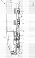
- Fig. 1 is a sectional elevational view of an armoured vehicle according to the invention;
- Fig. 2 is a perspective view of a power pack assembly for the vehicle;
- Fig. 3 is an elevational view of the power pack assembly;
- Fig. 4 is a plan view of the power pack assembly;
- Fig. 5 is an end elevational view of the power pack assembly;
- Fig. 6 is a sectional elevational view of a drop-box forming portion of a drive line of the vehicle;
- Fig. 7 is a perspective view of a transfer case assembly forming portion of the drive line of the vehicle;
- Fig. 8 is a sectional elevational view of the transfer case assembly;
- Fig. 9 is a sectional plan view of the transfer case assembly;
- Fig. 10 is a perspective view if a through-drive axle unit forming portion of the vehicle drive line;
- Fig. 11 is an elevational view of the through-drive axle unit;
- Fig. 12 is a sectional elevational view of the through-drive axle unit;
- Fig. 13 is a sectional plan view of the through-drive axle unit;
- Fig. 14 is a perspective view of a final-drive axle unit forming portion of the vehicle drive line;
- Fig. 15 is a sectional plan view of the final-drive axle;
- Fig. 16 is a sectional elevational view of the final-drive axle assembly;
- Fig. 17 is a sectional elevational view of another armoured vehicle according to a second embodiment of the invention;
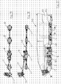
- Fig. 18 is an elevational view showing a drive line of the vehicle shown in Fig. 17;
- Fig. 19 is a plan view of the drive line of Fig. 18;
- Fig. 20 is a sectional elevational view of a drop-box forming portion of the drive line of the vehicle of Fig. 17;
- Fig. 21 is a perspective view of a transfer case assembly for the drive line of the vehicle of Fig. 17.
- Fig. 22 is an elevational view of the transfer case assembly shown in Fig. 21;
- Fig. 23 is a sectional elevational view of the transfer case assembly shown in Fig. 21;
- Fig. 24 is a perspective view of a through drive axle unit forming portion of the drive line of the vehicle of Fig. 17;
- Fig. 25 is an elevational view of the through-drive axle unit shown in Fig. 24;
- Fig. 26 is a sectional elevational view of the through-drive axle unit shown in Fig. 24;
- Fig. 27 is a perspective view of a final-drive axle unit forming portion of the drive-line of the vehicle shown in Fig. 17;
- Fig. 28 is an elevational view of the final-drive axle unit shown in Fig. 27; and
- Fig. 29 is a sectional elevational view of the final-drive axle unit shown in Fig. 27.
- Referring to the drawings, and initially to Figs. 1 to 16 thereof there is illustrated an armoured vehicle according to the invention indicated generally by the reference numeral 1. The armoured vehicle 1 has an
armoured vehicle body 2, an interior of which is adapted for the carriage of personnel and/or cargo. A number, in this case four, of spaced-apart driveable wheel (axles body 2. A power pack assembly (Fig. 2) indicated generally by thereference numeral 8 is mounted within thevehicle body 2 and is driveably connected to eachdriveable wheel axle - Preferably a modular
power pack assembly 8 is provided having an engine in line with an associatedtransmission 10 and drop-box assembly 11 mounted together, preferably on a sub frame, forming an integral modular unit which in turn is demountably secured within thevehicle body 2. Conveniently an engine cooling system may also be mounted on the sub frame. This modular power pack assembly advantageously facilitates ease of removal and replacement of thepower pack 8 in the field. Also the power pack assembly can be tested outside the vehicle engine compartment before mounting in the vehicle. - It will be noted that the
engine 9,transmission 10 and drop-box 11 are mounted on the sub frame with the drop-box 11 foremost such that the drive output from thetransmission 10 faces forwardly on the sub frame and is connected to a rearwardly facingdrive input 15 of the drop-box 11 and adrive output 16 of the drop-box 11 faces rearwardly for onward drive transmission via apropeller shaft 17 with atransfer case 18 which incorporates the seconddriveable axle 4. - The drop-
box 11 has ahousing 20. At the drive input 15 adrive input shaft 21 is rotatably mounted. Thedrive input shaft 21 carries aninput gear 22 which drives anintermediate gear 23 rotatably mounted on thehousing 20 which in turn drives anoutput gear 24 also rotatably mounted on thehousing 20. Acoupling 26 is mounted on theoutput gear 24 at thedrive output 16 for connection to thepropeller shaft 17 for onward drive transmission. Abrake disc 28 mounted on thecoupling 26 cooperates with an associatedcalliper 29 to provide a parking brake. A drive disconnect means 29a mounted on thehousing 20 is operable to disconnect drive from the engine to the driveable wheel (axles - It will be noted that the
transmission 10 anddrop box 11 each have separate casing with separate oil supplies. - The
transfer case 18 is shown in more detail in Fig. 7 to 9. Thetransfer case 18 has ahousing 35 within which is rotatably mounted adrive input shaft 36 having aninput end 37 for connection to thepropeller shaft 17. Adrive input gear 39 on thedrive shaft 36 engages with an associatedfollower gear 42 forming portion of adifferential unit 44. Afirst output shaft 46 of thedifferential unit 44 is rotatably supported on thehousing 35 and has as its outer end acoupling 47 for connection to asecond propeller shaft 48 for onward drive transmission towards a rear of the vehicle as can be seen in Fig. 1. A seconddrive output shaft 50 of thedifferential unit 44 driveably engages an associatedfollower gear 52 of a seconddifferential unit 54 mounted within thehousing 35. This splits the drive via a forwarddrive output shaft 56 rotatably mounted on thehousing 35 and terminating in acoupling 57 for connection via a third propeller shaft 58 (Fig. 1) with the first orfront drive axle 3 of the vehicle 1. A seconddrive output shaft 60, also rotatably mounted with thehousing 35, driveably connects to an axledifferential unit 62 of the seconddriveable wheel axle 4 which is integral with thetransfer case 18, for onward drive transmission via transverse drive outputs 63 to wheels at either side of thetransfer case 18. Anemergency steering pump 64 is mounted on thehousing 35 and is driveably connected to thedrive input shaft 36. - A
bulkhead seal 65, formed by a rubber bellows or the like, sealingly engages with a vertical bulkhead within thevehicle body 2 to provide a watertight seal between alower portion 66 of thebody 2 within which thetransfer case 18 and driveable wheel (axles upper portion 67 of thebody 2 forming an interior cabin of the vehicle 1. - Rearward drive transmission from the
transfer case 18 through thepropeller shaft 48 is to a throughdrive axle unit 70 which incorporates the thirddriveable wheel axle 5. The throughdrive axle unit 70 has ahousing 71. Adrive input coupling 72 for connection to thepropeller shaft 48 is mounted on adrive input shaft 73 which is rotatably mounted within thehousing 71. Adrive input gear 74 mounted on thedrive shaft 73 is driveably engaged with acomplementary gear 75 forming portion of adifferential unit 76. Thedifferential unit 76 has a firstdrive output shaft 78 rotatably mounted on thehousing 71 and terminating in acoupling 79 for connection to a final propeller shaft connected to the rearmostdriveable wheel axle 6. A seconddrive output shaft 82 rotatably mounted within thehousing 71 connects to an axledifferential unit 84 of thedriveable wheel axle 5 which is incorporated in the throughdrive axle unit 70 which delivers drive through transverse drive outputs 85 to wheels. - The final
drivable wheel axle 6 is shown in more detail in Figs. 14 to 16. This has aninput coupling 90 for connection to a propeller shaft delivering the drive to the finaldrivable wheel axle 6. Drive connects through an axledifferential unit 92 mounted within ahousing 91 of the finaldrivable wheel axle 6 and is delivered outwardly through transverse drive outputs 93 and by means of propeller shafts or the like to wheels at each side of the finaldrivable wheel axle 6. - Referring now to Figs. 17 to 29 there is illustrated an armoured vehicle according to a second embodiment of the invention indicated generally by the
reference numeral 100. Parts similar to those described previously are assigned the same reference numerals. - Referring initially to Fig. 17 it will be noted that the
vehicle 100 is amphibious having a watertightinterior compartment 101 above a watertightfloor bulk head 102 for carriage of cargo and/or personal. The drive line from thedrive transfer case 18 onwards is located outside thiswatertight compartment 101. Thepropeller shaft 17 passes through anopening 103 in thefloor bulk head 102 of thecompartment 101. A watertight seal is achieved at thisopening 103 by means of a sealingelement 106 mounted between thedrive transfer case 18, at the inlet of saiddrive transfer case 18, and a surround of theopening 103. All of the driveable wheel (axles axles - Referring to Fig. 20 a modified
drop box 111 for thevehicle 100 is shown. Thedrop box 111 has ahousing 120. Similarly to thedrop box 11 described previously thedrop box 111 has adrive input shaft 121 withdrive input gear 122 driving anintermediate gear 123 which in turn drives anoutput gear 124. In this case thedrive input shaft 121 has anadaptor 125 at thedrive input 15 end to facilitate close coupling to thetransmission 10. Whilst close coupled thistransmission 10 and thedrop box 111 have separate casings with separate oil supplies. Also, theintermediate gear 123 carries thebrake disc 28. Further, anemergency steering pump 127 is mounted on thehousing 120 and driveably connected to theoutput gear 124. Adrive output flange 128 of thedrive output gear 124 is in turn driveably connected to the road wheels of thevehicle 100 such that thesteering pump 127 is driven when the vehicle is being towed. Adrive disconnect 129 mounted on thehousing 120 is operable to disconnect drive from the engine to the driveable wheel (axles - Referring now to Figs. 21 to 23 a modified
transfer case 118 for thevehicle 100 is shown. Adrive input 136 connects through adifferential unit 137 with adrive shaft 138. A forwarddrive input gear 139 drives afollower gear 140 which in turn driveably connects throughdifferential unit 141 with aforward drive output 142 andrearward drive output 143 driving an axledifferential unit 144 driveably connected to wheels mounted at each side of the axledifferential unit 144. Thedrive shaft 138 also drives an onwarddrive transmission gear 146 which drives afollower 147 withdrive output connector 148 for rearward drive transmission by propeller shaft to the throughdrive axle unit 70. - The through
drive axle unit 70 is shown in Figs. 24 to 26 and has anouter casing 170 with afront drive input 171 connected throughdifferential unit 172 with arear drive output 173 which in turn is connected bypropeller shaft 174 to the rearmostdriveable wheel axle 6.Drive output 175 is also taken to vehicle wheels mounted on either side of theaxle casing 170. - A final
drivable wheel axle 6 is shown in Figs. 27 to 29 and has anouter casing 191 within which are mounted adrive input 192 connected to an axledifferential unit 193 which is connected byaxle drive output 194 to vehicle wheels mounted at each side of theouter casing 191. - The invention is not limited to the embodiments hereinbefore described which may be varied in both construction and detail within the scope of the appended claims.
Claims (12)
- An armoured vehicle (1, 100) including:an armoured vehicle body (2),a number of spaced-apart wheel axles (3, 4, 5, 6) being mounted on the body (2),at least two of said wheel axles (3, 4, 5, 6) being a driveable wheel axle,a power pack (8) mounted in the vehicle body (2),a drive line driveably connecting said power pack (8) to said driveable wheel axles (3, 4, 5, 6),said power pack (8) being mounted on the vehicle body (2) above said wheel axles (3, 4, 5, 6) and said drive line including a drop-box (11) to transmit the drive from the power pack (8) to a drive transfer case (18) which splits the drive for delivery to the driveable wheel (axles 3, 4, 5, 6).
- An armoured vehicle (1, 100) as claimed in claim 1 wherein a modular power pack assembly (8) is provided in which an engine (9), an associated transmission (10) and drop-box assembly (11) and an engine cooling system are mounted together in an integral modular unit which in turn is demountably secured within the vehicle body (2).
- An armoured vehicle (1, 100) as claimed in claim 2 wherein the engine (9), transmission (10) and drop-box (11) are mounted on a sub frame with the drop-box (11) foremost such that a drive shaft coming from the engine and transmission faces forwardly on the sub frame and is connected to a rearwardly facing drive input (15) of the drop-box (11), and a drive output (16) of the drop-box (11) faces rearwardly for onward drive transmission to the transfer case (18).
- An armoured vehicle (1, 100) as claimed in any preceding claiming wherein the drop-box (11) has a drive disconnect means (29a) which is operable to disconnect drive from the engine (8) to the driveable wheel axles (3, 4, 5, 6).
- An armoured vehicle (1, 100) as claimed in any preceding claim wherein the drop-box (11) includes a parking brake.
- An armoured vehicle (1, 100) as claimed in claim 5 wherein the parking brake is located downstream of the drive disconnect means (29a) in the drop-box (11).
- An armoured vehicle (1, 100) as claimed in any preceding claim wherein the drop-box (11) is close coupled to the transmission (10) and said transmission (10) and said drop-box (11) have separate housings.
- An armoured vehicle (1, 100) as claimed in any preceding claim wherein the drop-box (11) drive output (16) is connected to the drive transfer case (18) which splits the drive, said drive transfer case (18) having a transverse pair of first drive outputs (63) for connection to wheels at each side of the drive transfer case (18) on a first driveable wheel axle (4),
a forward second drive output (56) at a front of the drive transfer case (18) connected to a forward second driveable wheel axle (3) of the vehicle, and
a rearward third drive output (47) at a rear of the drive transfer case (18) connected to a rearward third driveable wheel axle (5) of the vehicle. - An armoured vehicle (1, 100) as claimed in any preceding claim wherein an emergency steering pump (64, 127) is mounted on either the drop box (11) or drive transfer case (18) and is driveably connected to the road wheels of the vehicle such that the emergency steering pump (64, 127) is driven by rotation of the road wheels when the vehicle is being towed.
- An armoured vehicle (1, 100) as claimed in any preceding claim wherein the vehicle is amphibious and the vehicle body (2) has a sealed interior compartment (67, 101) which is sealed against water ingress below the water line when the vehicle is floating in a body of water, the drive transfer case (18) is located outside said sealed interior compartment (67, 101) of the vehicle body (2), with a liquid tight seal (65, 106) being provided at a drive inlet of the drive transfer case between the drive transfer case (18) and an opening in a vertical bulkhead of said sealed interior compartment (67, 101) through which the drive passes from the drop-box (11) to the drive transfer case (18).
- An armoured vehicle (1, 100) as claimed in any preceding claim wherein the vehicle includes a number of differentials in the driveline and some or all of the differentials in the driveline incorporate an automatically engaged limited slip differential.
- An armoured vehicle (1, 100) as claimed in any preceding claim wherein a through drive axle unit (70) is mounted in the drive line downstream of the transfer case (18), said through drive axle unit (70) having a drive input (72) connected to a drive output (47) of the transfer case (18), a first transverse drive output connected to driveable wheels mounted at each side of the through drive axle unit and a second drive output (79) for onward transmission of drive to a further drive axle (6) located downstream of the through drive axle unit (70) in the drive line.
Priority Applications (1)
| Application Number | Priority Date | Filing Date | Title |
|---|---|---|---|
| PL07106757T PL1847414T3 (en) | 2006-04-21 | 2007-04-23 | Improvements in and relating to drivelines |
Applications Claiming Priority (1)
| Application Number | Priority Date | Filing Date | Title |
|---|---|---|---|
| IE20060318A IES20060318A2 (en) | 2006-04-21 | 2006-04-21 | Improvements relating to drivelines |
Publications (3)
| Publication Number | Publication Date |
|---|---|
| EP1847414A2 true EP1847414A2 (en) | 2007-10-24 |
| EP1847414A3 EP1847414A3 (en) | 2009-07-01 |
| EP1847414B1 EP1847414B1 (en) | 2013-07-03 |
Family
ID=38293352
Family Applications (1)
| Application Number | Title | Priority Date | Filing Date |
|---|---|---|---|
| EP07106757.3A Not-in-force EP1847414B1 (en) | 2006-04-21 | 2007-04-23 | Improvements in and relating to drivelines |
Country Status (5)
| Country | Link |
|---|---|
| EP (1) | EP1847414B1 (en) |
| IE (1) | IES20060318A2 (en) |
| PL (1) | PL1847414T3 (en) |
| SG (1) | SG136916A1 (en) |
| TW (1) | TWI316995B (en) |
Family Cites Families (6)
| Publication number | Priority date | Publication date | Assignee | Title |
|---|---|---|---|---|
| FR2109168A5 (en) * | 1970-10-06 | 1972-05-26 | Panhard Levassor Const | |
| US4542801A (en) * | 1981-12-04 | 1985-09-24 | Caterpillar Tractor Co. | Vehicle transfer gear mechanism |
| US4771852A (en) * | 1985-06-05 | 1988-09-20 | Toyota Jidosha Kabushiki Kaisha | Four wheel drive vehicle transfer and control apparatus |
| JP3406421B2 (en) * | 1995-06-13 | 2003-05-12 | 株式会社エクセディ | transmission |
| EP1231093B1 (en) * | 2001-02-09 | 2008-05-07 | Technology Investments Limited | A vehicle driveline |
| ATE470591T1 (en) * | 2003-04-01 | 2010-06-15 | Technology Investments Ltd | DRIVE CHAIN TO A VEHICLE |
-
2006
- 2006-04-21 IE IE20060318A patent/IES20060318A2/en not_active IP Right Cessation
- 2006-09-29 TW TW095136446A patent/TWI316995B/en not_active IP Right Cessation
-
2007
- 2007-04-23 PL PL07106757T patent/PL1847414T3/en unknown
- 2007-04-23 SG SG200702970-5A patent/SG136916A1/en unknown
- 2007-04-23 EP EP07106757.3A patent/EP1847414B1/en not_active Not-in-force
Non-Patent Citations (1)
| Title |
|---|
| None |
Also Published As
| Publication number | Publication date |
|---|---|
| TWI316995B (en) | 2009-11-11 |
| IES20060318A2 (en) | 2007-10-31 |
| SG136916A1 (en) | 2007-11-29 |
| PL1847414T3 (en) | 2014-01-31 |
| EP1847414A3 (en) | 2009-07-01 |
| EP1847414B1 (en) | 2013-07-03 |
Similar Documents
| Publication | Publication Date | Title |
|---|---|---|
| US7011557B2 (en) | Amphibious vehicle | |
| AU2001282320B2 (en) | Power train | |
| JP4805350B2 (en) | Vehicle drive system | |
| US20060197375A1 (en) | Hydraulic hybrid four wheel drive | |
| CN113815393A (en) | Axle assembly with electric motor | |
| US5348516A (en) | Transaxle for midship transversely mounted engine | |
| AU2001282320A1 (en) | Power train | |
| KR100790066B1 (en) | Power Train | |
| GB2454563A (en) | A power take-off for all-wheel-drive systems | |
| US20200269686A1 (en) | Modular drive train and a vehicle comprising such a drive train | |
| EP2095987B1 (en) | Power transmission apparatus of working vehicle | |
| GB2473954A (en) | A sealing system for a hull of an amphibious vehicle | |
| EP1847414B1 (en) | Improvements in and relating to drivelines | |
| CN219505834U (en) | Electric all-terrain vehicle | |
| IES84858Y1 (en) | Improvements relating to drivelines | |
| US4479395A (en) | Differential gear housing mounted power take-off unit | |
| US20120018275A1 (en) | Rear Driveline Disconnect Apparatus | |
| EP0377130A1 (en) | Tandem drive axle system | |
| EP1468859B1 (en) | A vehicle driveline | |
| US1273519A (en) | Power-transmitting means for motor-driven vehicles. | |
| WO1993005974A1 (en) | Removable drive system for a skid steer loader | |
| US10759397B2 (en) | Vehicle drive train braking | |
| US20100063701A1 (en) | Brake based viscous coupling alternative vehicle differential | |
| CN101357588B (en) | A final drive assembly for a vehicule | |
| IE86014B1 (en) | A sealing system |
Legal Events
| Date | Code | Title | Description |
|---|---|---|---|
| PUAI | Public reference made under article 153(3) epc to a published international application that has entered the european phase |
Free format text: ORIGINAL CODE: 0009012 |
|
| AK | Designated contracting states |
Kind code of ref document: A2 Designated state(s): AT BE BG CH CY CZ DE DK EE ES FI FR GB GR HU IE IS IT LI LT LU LV MC MT NL PL PT RO SE SI SK TR |
|
| AX | Request for extension of the european patent |
Extension state: AL BA HR MK YU |
|
| PUAL | Search report despatched |
Free format text: ORIGINAL CODE: 0009013 |
|
| AK | Designated contracting states |
Kind code of ref document: A3 Designated state(s): AT BE BG CH CY CZ DE DK EE ES FI FR GB GR HU IE IS IT LI LT LU LV MC MT NL PL PT RO SE SI SK TR |
|
| AX | Request for extension of the european patent |
Extension state: AL BA HR MK RS |
|
| 17P | Request for examination filed |
Effective date: 20100104 |
|
| 17Q | First examination report despatched |
Effective date: 20100129 |
|
| AKX | Designation fees paid |
Designated state(s): AT BE BG CH CY CZ DE DK EE ES FI FR GB GR HU IE IS IT LI LT LU LV MC MT NL PL PT RO SE SI SK TR |
|
| GRAP | Despatch of communication of intention to grant a patent |
Free format text: ORIGINAL CODE: EPIDOSNIGR1 |
|
| GRAS | Grant fee paid |
Free format text: ORIGINAL CODE: EPIDOSNIGR3 |
|
| GRAA | (expected) grant |
Free format text: ORIGINAL CODE: 0009210 |
|
| AK | Designated contracting states |
Kind code of ref document: B1 Designated state(s): AT BE BG CH CY CZ DE DK EE ES FI FR GB GR HU IE IS IT LI LT LU LV MC MT NL PL PT RO SE SI SK TR |
|
| REG | Reference to a national code |
Ref country code: GB Ref legal event code: FG4D |
|
| REG | Reference to a national code |
Ref country code: AT Ref legal event code: REF Ref document number: 619510 Country of ref document: AT Kind code of ref document: T Effective date: 20130715 Ref country code: CH Ref legal event code: EP |
|
| REG | Reference to a national code |
Ref country code: IE Ref legal event code: FG4D |
|
| REG | Reference to a national code |
Ref country code: DE Ref legal event code: R096 Ref document number: 602007031354 Country of ref document: DE Effective date: 20130829 |
|
| PG25 | Lapsed in a contracting state [announced via postgrant information from national office to epo] |
Ref country code: SI Free format text: LAPSE BECAUSE OF FAILURE TO SUBMIT A TRANSLATION OF THE DESCRIPTION OR TO PAY THE FEE WITHIN THE PRESCRIBED TIME-LIMIT Effective date: 20130703 |
|
| REG | Reference to a national code |
Ref country code: AT Ref legal event code: MK05 Ref document number: 619510 Country of ref document: AT Kind code of ref document: T Effective date: 20130703 |
|
| REG | Reference to a national code |
Ref country code: NL Ref legal event code: VDEP Effective date: 20130703 |
|
| REG | Reference to a national code |
Ref country code: LT Ref legal event code: MG4D |
|
| PG25 | Lapsed in a contracting state [announced via postgrant information from national office to epo] |
Ref country code: PT Free format text: LAPSE BECAUSE OF FAILURE TO SUBMIT A TRANSLATION OF THE DESCRIPTION OR TO PAY THE FEE WITHIN THE PRESCRIBED TIME-LIMIT Effective date: 20131104 Ref country code: IS Free format text: LAPSE BECAUSE OF FAILURE TO SUBMIT A TRANSLATION OF THE DESCRIPTION OR TO PAY THE FEE WITHIN THE PRESCRIBED TIME-LIMIT Effective date: 20131103 Ref country code: BE Free format text: LAPSE BECAUSE OF FAILURE TO SUBMIT A TRANSLATION OF THE DESCRIPTION OR TO PAY THE FEE WITHIN THE PRESCRIBED TIME-LIMIT Effective date: 20130703 Ref country code: LT Free format text: LAPSE BECAUSE OF FAILURE TO SUBMIT A TRANSLATION OF THE DESCRIPTION OR TO PAY THE FEE WITHIN THE PRESCRIBED TIME-LIMIT Effective date: 20130703 Ref country code: SE Free format text: LAPSE BECAUSE OF FAILURE TO SUBMIT A TRANSLATION OF THE DESCRIPTION OR TO PAY THE FEE WITHIN THE PRESCRIBED TIME-LIMIT Effective date: 20130703 Ref country code: CY Free format text: LAPSE BECAUSE OF FAILURE TO SUBMIT A TRANSLATION OF THE DESCRIPTION OR TO PAY THE FEE WITHIN THE PRESCRIBED TIME-LIMIT Effective date: 20130619 Ref country code: AT Free format text: LAPSE BECAUSE OF FAILURE TO SUBMIT A TRANSLATION OF THE DESCRIPTION OR TO PAY THE FEE WITHIN THE PRESCRIBED TIME-LIMIT Effective date: 20130703 |
|
| REG | Reference to a national code |
Ref country code: PL Ref legal event code: T3 |
|
| PG25 | Lapsed in a contracting state [announced via postgrant information from national office to epo] |
Ref country code: FI Free format text: LAPSE BECAUSE OF FAILURE TO SUBMIT A TRANSLATION OF THE DESCRIPTION OR TO PAY THE FEE WITHIN THE PRESCRIBED TIME-LIMIT Effective date: 20130703 Ref country code: ES Free format text: LAPSE BECAUSE OF FAILURE TO SUBMIT A TRANSLATION OF THE DESCRIPTION OR TO PAY THE FEE WITHIN THE PRESCRIBED TIME-LIMIT Effective date: 20131014 Ref country code: GR Free format text: LAPSE BECAUSE OF FAILURE TO SUBMIT A TRANSLATION OF THE DESCRIPTION OR TO PAY THE FEE WITHIN THE PRESCRIBED TIME-LIMIT Effective date: 20131004 Ref country code: NL Free format text: LAPSE BECAUSE OF FAILURE TO SUBMIT A TRANSLATION OF THE DESCRIPTION OR TO PAY THE FEE WITHIN THE PRESCRIBED TIME-LIMIT Effective date: 20130703 Ref country code: LV Free format text: LAPSE BECAUSE OF FAILURE TO SUBMIT A TRANSLATION OF THE DESCRIPTION OR TO PAY THE FEE WITHIN THE PRESCRIBED TIME-LIMIT Effective date: 20130703 |
|
| PG25 | Lapsed in a contracting state [announced via postgrant information from national office to epo] |
Ref country code: CY Free format text: LAPSE BECAUSE OF FAILURE TO SUBMIT A TRANSLATION OF THE DESCRIPTION OR TO PAY THE FEE WITHIN THE PRESCRIBED TIME-LIMIT Effective date: 20130703 |
|
| PG25 | Lapsed in a contracting state [announced via postgrant information from national office to epo] |
Ref country code: SK Free format text: LAPSE BECAUSE OF FAILURE TO SUBMIT A TRANSLATION OF THE DESCRIPTION OR TO PAY THE FEE WITHIN THE PRESCRIBED TIME-LIMIT Effective date: 20130703 Ref country code: RO Free format text: LAPSE BECAUSE OF FAILURE TO SUBMIT A TRANSLATION OF THE DESCRIPTION OR TO PAY THE FEE WITHIN THE PRESCRIBED TIME-LIMIT Effective date: 20130703 Ref country code: EE Free format text: LAPSE BECAUSE OF FAILURE TO SUBMIT A TRANSLATION OF THE DESCRIPTION OR TO PAY THE FEE WITHIN THE PRESCRIBED TIME-LIMIT Effective date: 20130703 Ref country code: CZ Free format text: LAPSE BECAUSE OF FAILURE TO SUBMIT A TRANSLATION OF THE DESCRIPTION OR TO PAY THE FEE WITHIN THE PRESCRIBED TIME-LIMIT Effective date: 20130703 Ref country code: DK Free format text: LAPSE BECAUSE OF FAILURE TO SUBMIT A TRANSLATION OF THE DESCRIPTION OR TO PAY THE FEE WITHIN THE PRESCRIBED TIME-LIMIT Effective date: 20130703 |
|
| PLBE | No opposition filed within time limit |
Free format text: ORIGINAL CODE: 0009261 |
|
| STAA | Information on the status of an ep patent application or granted ep patent |
Free format text: STATUS: NO OPPOSITION FILED WITHIN TIME LIMIT |
|
| PG25 | Lapsed in a contracting state [announced via postgrant information from national office to epo] |
Ref country code: IT Free format text: LAPSE BECAUSE OF FAILURE TO SUBMIT A TRANSLATION OF THE DESCRIPTION OR TO PAY THE FEE WITHIN THE PRESCRIBED TIME-LIMIT Effective date: 20130703 |
|
| 26N | No opposition filed |
Effective date: 20140404 |
|
| REG | Reference to a national code |
Ref country code: DE Ref legal event code: R097 Ref document number: 602007031354 Country of ref document: DE Effective date: 20140404 |
|
| REG | Reference to a national code |
Ref country code: DE Ref legal event code: R119 Ref document number: 602007031354 Country of ref document: DE |
|
| PG25 | Lapsed in a contracting state [announced via postgrant information from national office to epo] |
Ref country code: MC Free format text: LAPSE BECAUSE OF FAILURE TO SUBMIT A TRANSLATION OF THE DESCRIPTION OR TO PAY THE FEE WITHIN THE PRESCRIBED TIME-LIMIT Effective date: 20130703 Ref country code: LU Free format text: LAPSE BECAUSE OF FAILURE TO SUBMIT A TRANSLATION OF THE DESCRIPTION OR TO PAY THE FEE WITHIN THE PRESCRIBED TIME-LIMIT Effective date: 20140423 |
|
| REG | Reference to a national code |
Ref country code: CH Ref legal event code: PL |
|
| REG | Reference to a national code |
Ref country code: DE Ref legal event code: R119 Ref document number: 602007031354 Country of ref document: DE Effective date: 20141101 |
|
| REG | Reference to a national code |
Ref country code: FR Ref legal event code: ST Effective date: 20141231 |
|
| REG | Reference to a national code |
Ref country code: IE Ref legal event code: MM4A |
|
| PG25 | Lapsed in a contracting state [announced via postgrant information from national office to epo] |
Ref country code: LI Free format text: LAPSE BECAUSE OF NON-PAYMENT OF DUE FEES Effective date: 20140430 Ref country code: CH Free format text: LAPSE BECAUSE OF NON-PAYMENT OF DUE FEES Effective date: 20140430 Ref country code: DE Free format text: LAPSE BECAUSE OF NON-PAYMENT OF DUE FEES Effective date: 20141101 |
|
| PG25 | Lapsed in a contracting state [announced via postgrant information from national office to epo] |
Ref country code: FR Free format text: LAPSE BECAUSE OF NON-PAYMENT OF DUE FEES Effective date: 20140430 |
|
| PG25 | Lapsed in a contracting state [announced via postgrant information from national office to epo] |
Ref country code: IE Free format text: LAPSE BECAUSE OF NON-PAYMENT OF DUE FEES Effective date: 20140423 |
|
| PG25 | Lapsed in a contracting state [announced via postgrant information from national office to epo] |
Ref country code: MT Free format text: LAPSE BECAUSE OF FAILURE TO SUBMIT A TRANSLATION OF THE DESCRIPTION OR TO PAY THE FEE WITHIN THE PRESCRIBED TIME-LIMIT Effective date: 20130703 |
|
| PG25 | Lapsed in a contracting state [announced via postgrant information from national office to epo] |
Ref country code: BG Free format text: LAPSE BECAUSE OF FAILURE TO SUBMIT A TRANSLATION OF THE DESCRIPTION OR TO PAY THE FEE WITHIN THE PRESCRIBED TIME-LIMIT Effective date: 20130703 |
|
| PG25 | Lapsed in a contracting state [announced via postgrant information from national office to epo] |
Ref country code: HU Free format text: LAPSE BECAUSE OF FAILURE TO SUBMIT A TRANSLATION OF THE DESCRIPTION OR TO PAY THE FEE WITHIN THE PRESCRIBED TIME-LIMIT; INVALID AB INITIO Effective date: 20070423 Ref country code: TR Free format text: LAPSE BECAUSE OF FAILURE TO SUBMIT A TRANSLATION OF THE DESCRIPTION OR TO PAY THE FEE WITHIN THE PRESCRIBED TIME-LIMIT Effective date: 20130703 |
|
| PGFP | Annual fee paid to national office [announced via postgrant information from national office to epo] |
Ref country code: GB Payment date: 20170427 Year of fee payment: 11 |
|
| PGFP | Annual fee paid to national office [announced via postgrant information from national office to epo] |
Ref country code: PL Payment date: 20170421 Year of fee payment: 11 |
|
| GBPC | Gb: european patent ceased through non-payment of renewal fee |
Effective date: 20180423 |
|
| PG25 | Lapsed in a contracting state [announced via postgrant information from national office to epo] |
Ref country code: GB Free format text: LAPSE BECAUSE OF NON-PAYMENT OF DUE FEES Effective date: 20180423 |
|
| PG25 | Lapsed in a contracting state [announced via postgrant information from national office to epo] |
Ref country code: PL Free format text: LAPSE BECAUSE OF NON-PAYMENT OF DUE FEES Effective date: 20180423 |