EP1847230A1 - System and method for reducing patient return electrode current concentrations - Google Patents
System and method for reducing patient return electrode current concentrations Download PDFInfo
- Publication number
- EP1847230A1 EP1847230A1 EP07007783A EP07007783A EP1847230A1 EP 1847230 A1 EP1847230 A1 EP 1847230A1 EP 07007783 A EP07007783 A EP 07007783A EP 07007783 A EP07007783 A EP 07007783A EP 1847230 A1 EP1847230 A1 EP 1847230A1
- Authority
- EP
- European Patent Office
- Prior art keywords
- return electrode
- conductive element
- electrosurgical
- conductive
- current
- Prior art date
- Legal status (The legal status is an assumption and is not a legal conclusion. Google has not performed a legal analysis and makes no representation as to the accuracy of the status listed.)
- Granted
Links
- 238000000034 method Methods 0.000 title description 16
- 238000001514 detection method Methods 0.000 claims description 15
- 239000000853 adhesive Substances 0.000 description 6
- 230000001070 adhesive effect Effects 0.000 description 6
- 238000001356 surgical procedure Methods 0.000 description 6
- 239000012790 adhesive layer Substances 0.000 description 4
- 238000009529 body temperature measurement Methods 0.000 description 4
- 238000010438 heat treatment Methods 0.000 description 4
- 230000001965 increasing effect Effects 0.000 description 4
- 230000004044 response Effects 0.000 description 4
- 239000011888 foil Substances 0.000 description 3
- 230000000694 effects Effects 0.000 description 2
- 235000015110 jellies Nutrition 0.000 description 2
- 239000008274 jelly Substances 0.000 description 2
- 239000000463 material Substances 0.000 description 2
- 239000002184 metal Substances 0.000 description 2
- 238000007674 radiofrequency ablation Methods 0.000 description 2
- 230000005355 Hall effect Effects 0.000 description 1
- 239000004820 Pressure-sensitive adhesive Substances 0.000 description 1
- 230000003466 anti-cipated effect Effects 0.000 description 1
- 238000013528 artificial neural network Methods 0.000 description 1
- 239000008280 blood Substances 0.000 description 1
- 210000004369 blood Anatomy 0.000 description 1
- 230000008859 change Effects 0.000 description 1
- 230000001112 coagulating effect Effects 0.000 description 1
- 239000004020 conductor Substances 0.000 description 1
- 238000010276 construction Methods 0.000 description 1
- 230000007423 decrease Effects 0.000 description 1
- 230000003247 decreasing effect Effects 0.000 description 1
- 230000001747 exhibiting effect Effects 0.000 description 1
- 231100001261 hazardous Toxicity 0.000 description 1
- 238000002847 impedance measurement Methods 0.000 description 1
- 230000001939 inductive effect Effects 0.000 description 1
- 230000001788 irregular Effects 0.000 description 1
- 238000005259 measurement Methods 0.000 description 1
- 230000007246 mechanism Effects 0.000 description 1
- 239000000203 mixture Substances 0.000 description 1
- 230000004048 modification Effects 0.000 description 1
- 238000012986 modification Methods 0.000 description 1
- 230000001225 therapeutic effect Effects 0.000 description 1
- 230000000007 visual effect Effects 0.000 description 1
Images


Classifications
-
- A—HUMAN NECESSITIES
- A61—MEDICAL OR VETERINARY SCIENCE; HYGIENE
- A61B—DIAGNOSIS; SURGERY; IDENTIFICATION
- A61B18/00—Surgical instruments, devices or methods for transferring non-mechanical forms of energy to or from the body
- A61B18/04—Surgical instruments, devices or methods for transferring non-mechanical forms of energy to or from the body by heating
- A61B18/12—Surgical instruments, devices or methods for transferring non-mechanical forms of energy to or from the body by heating by passing a current through the tissue to be heated, e.g. high-frequency current
- A61B18/14—Probes or electrodes therefor
- A61B18/16—Indifferent or passive electrodes for grounding
-
- A—HUMAN NECESSITIES
- A61—MEDICAL OR VETERINARY SCIENCE; HYGIENE
- A61B—DIAGNOSIS; SURGERY; IDENTIFICATION
- A61B18/00—Surgical instruments, devices or methods for transferring non-mechanical forms of energy to or from the body
- A61B18/04—Surgical instruments, devices or methods for transferring non-mechanical forms of energy to or from the body by heating
- A61B18/12—Surgical instruments, devices or methods for transferring non-mechanical forms of energy to or from the body by heating by passing a current through the tissue to be heated, e.g. high-frequency current
- A61B18/1206—Generators therefor
- A61B18/1233—Generators therefor with circuits for assuring patient safety
-
- A—HUMAN NECESSITIES
- A61—MEDICAL OR VETERINARY SCIENCE; HYGIENE
- A61B—DIAGNOSIS; SURGERY; IDENTIFICATION
- A61B17/00—Surgical instruments, devices or methods
- A61B2017/00017—Electrical control of surgical instruments
- A61B2017/00022—Sensing or detecting at the treatment site
- A61B2017/00026—Conductivity or impedance, e.g. of tissue
-
- A—HUMAN NECESSITIES
- A61—MEDICAL OR VETERINARY SCIENCE; HYGIENE
- A61B—DIAGNOSIS; SURGERY; IDENTIFICATION
- A61B18/00—Surgical instruments, devices or methods for transferring non-mechanical forms of energy to or from the body
- A61B2018/00636—Sensing and controlling the application of energy
- A61B2018/00696—Controlled or regulated parameters
- A61B2018/00767—Voltage
-
- A—HUMAN NECESSITIES
- A61—MEDICAL OR VETERINARY SCIENCE; HYGIENE
- A61B—DIAGNOSIS; SURGERY; IDENTIFICATION
- A61B18/00—Surgical instruments, devices or methods for transferring non-mechanical forms of energy to or from the body
- A61B2018/00636—Sensing and controlling the application of energy
- A61B2018/00773—Sensed parameters
- A61B2018/00827—Current
Definitions
- the present disclosure is directed to electrosurgical systems and methods and, more particularly, to patient return electrode systems and methods for performing monopolar surgery and RF ablation using the same.
- a source or active electrode delivers energy, such as radio frequency energy, from an electrosurgical generator to a patient.
- a return electrode carries the current back to the electrosurgical generator.
- the source electrode is typically a hand-held instrument placed by the surgeon at the surgical site and the high current density flow at this electrode creates the desired surgical effect of cutting, ablating and/or coagulating tissue.
- the patient return electrode is placed at a remote site from the source electrode and is typically in the form of a pad adhesively adhered to the patient.
- the return electrode typically has a relatively large patient contact surface area to minimize heat concentrations at that patient pad site (i.e., the smaller the surface area, the greater the current density and the greater the intensity of the heat.)
- the overall area of the return electrode that is adhered to the patient is generally important because it minimizes the chances of current concentrating in any one spot which may cause patient burns.
- a larger surface contact area is desirable to reduce heat intensity.
- the size of return electrodes is based on assumptions of the anticipated maximum current during a particular surgical procedure and the duty cycle (i.e., the percentage of time the generator is on) during the procedure.
- the first types of return electrodes were in the form of large metal plates covered with conductive jelly. Later, adhesive electrodes were developed with a single metal foil covered with conductive jelly or conductive adhesive.
- RECQMs Return Electrode Contact Quality Monitors
- These split electrodes consist of two separate conductive foils arranged as two halves of a single return electrode.
- the hardware circuit uses an AC signal between the two electrode halves to measure the impedance therebetween. This impedance measurement is indicative of how well the return electrode is adhered to the patient since the impedance between the two halves is directly related to the area of patient contact. That is, if the electrode begins to peel from the patient, the impedance increases since the contact area of the electrode decreases.
- Current RECQMs are designed to sense this change in impedance so that when the percentage increase in impedance exceeds a predetermined value or the measured impedance exceeds a threshold level, the electrosurgical generator is shut down to reduce the chances of burning the patient.
- each conductive pad would receive substantially the same amount of current, therefore reducing the possibility of a pad site burn. However, this is not always possible due to patient size, incorrect placement of pads, differing tissue consistencies, etc.
- the present disclosure is directed to patient return electrode systems and methods for performing monopolar surgery and RF ablation using the same.
- a return electrode for use in an electrosurgical system includes a non-conductive pad, and a plurality of concentric, electrically isolated conductive elements coupled to a surface of the non-conductive pad.
- Each conductive element defines a leading edge located in relatively close proximity to a source of electrosurgical energy.
- Each conductive element is independently electrically connectable to the source of electrosurgical energy.
- an electrosurgical system includes an electrosurgical generator, and a return electrode selectively connectable to the electrosurgical generator.
- the return electrode includes a plurality of concentric, electrically isolated conductive elements. Each conductive element defines a leading edge located in relative close proximity to the electrosurgical generator. Each conductive element is independently electrically connectable to the electrosurgical generator.
- a method of performing monopolar surgery includes the step of providing an electrosurgical system.
- the electrosurgical system includes an electrosurgical generator, and a return electrode connected to the electrosurgical generator, the return electrode including a plurality of concentric, electrically isolated conductive elements.
- Each conductive element defines a leading edge located in close proximity to the electrosurgical generator.
- Each conductive element is independently electrically connectable to the electrosurgical generator.
- the method further includes the steps of placing the return electrode into contact with a patient, generating electrosurgical energy via the electrosurgical generator, transmitting electrosurgical energy between an active electrode and the return electrode via the patient, measuring the current along the leading edge of each conductive element, and switching a respective conductive element out-of a circuit when the measured current along the leading edge of the respective conductive element exceeds a predetermined threshold current level.
- a return electrode pad has advantageously been designed which has the ability to relieve large current concentrations on a leading edge thereof and to make adjustments so as to reduce the current concentration at said leading edge thereof, thereby reducing the likelihood of patient burns.
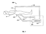
- FIG. 1 is a schematic illustration of a monopolar electrosurgical system
- FIG. 2 is a plan view of an electrosurgical return electrode according to one embodiment of the present disclosure, illustrating a conductive pad having a plurality of concentric conductive elements;
- FIG. 3 is a cross-sectional view of the electrosurgical return electrode as taken through 3-3 of FIG. 2;
- FIG. 4 is an enlarged schematic cross-sectional view of a portion of the return electrode of FIGS. 2 and 3;
- FIG. 5 is an electrical schematic of the electrosurgical system of FIG. 1 employing the return electrode of FIGS. 2-4.
- the electrosurgical system 100 includes a surgical instrument 110 (e.g., electrosurgical pencil, electrical scalpel, or other suitable active electrode) selectively connectable or permanently connected to a generator 120, a return electrode 200, a connection device 300 for connecting the return electrode 200 to generator 120, and a current detection system 400 disposed on or associated with the return electrode 200 (see FIG. 4).
- a surgical instrument 110 e.g., electrosurgical pencil, electrical scalpel, or other suitable active electrode
- return electrode 200 is illustrated in an operative position placed beneath a patient "P.”
- Electrosurgical energy is supplied to the surgical instrument 110 by the generator 120 via a cable 130 to cut, coagulate, blend, etc. tissue.
- the return electrode 200 returns energy delivered by the surgical instrument 110 to the patient "P" back to the generator 120 via return path 140.
- the electrosurgical energy flows from return electrode 200, through patient "P", to surgical instrument 110, and on to generator 120.
- a current detection system 400 is associated with return electrode 200 and is coupled to connection device 300 via a cable 250.
- Connection device 300 may be coupled to generator 120 (FIG. 1), may be coupled to return electrode 200 (FIGS. 2 and 3), may be disposed between return electrode 200 and a generator 120 (FIG. 4), or may be housed within generator 120.
- Return electrode 200 includes a non-conductive pad 210 having a top surface 212 and a bottom surface 214. Return electrode 200 is designed and configured to receive current during monopolar electrosurgery. While the figures depict return electrode 200 in a generally rectangular shape, return electrode 200 may have any suitable regular or irregular geometric shape, including and not limited to triangular, rectangular, circular, polygonal, etc.
- Return electrode 200 includes a plurality of conductive elements 220 supported on top surface 212 of pad 210. As seen in FIG. 2, return electrode 220 includes a plurality of concentric conductive elements 220a-220c supported on or disposed within top surface 212 of pad 210. Conductive elements 220a-220c are electrically isolated from one another.
- first conductive element 220a surrounds a second conductive element 220b, while second conductive element 220b surrounds a third conductive element 220c.
- Each conductive element 220a-220c may be formed as a foil of conductive material or other suitable highly conductive media.
- return electrode 200 may include any suitable number of conductive elements 220. Additionally, each conductive element 220 may have a uniform width or may have a varying width along the length thereof. Also, each conductive element 220 may have a different width as compared to other conductive elements 220 of return electrode 200. Any combination of these arrangements and/or configurations of conductive elements 220 falls within the scope of the present disclosure.
- the number of conductive elements 220 and the area/size/dimension of each conductive element 220 is selected and/or optimized in order to achieve the greatest effect in dissipating current concentrations and/or temperature concentrations.
- Each conductive element 220a-220c defines a leading edge 222a-222c, respectively.
- leading edge is defined as the edge or corner of each conductive element 220a-220c that is closest to the source of energy or generator 120, or closest to connection device 300.
- Each conductive element 220a-220c is separately and independently electrically connected or connectable to generator 120 and/or to a processor or computer 180, as seen in FIG. 4.
- computer 180 switches conductive elements 220a-220c into and out of the electrosurgical circuit (i.e., between being capable of transmitting/receiving electrosurgical current/energy and being incapable of transmitting/receiving electrosurgical current/energy) in order to move the leading edges 222a-222c to different locations along return electrode 200.
- any current concentrations and/or temperature concentrations that may occur are distributed along the surface of return electrode 200.
- computer 180 may switch the conductive elements 220a-220c into or out of the circuit at predefined or predetermined intervals, may sequentially cycle through conductive elements 220a-220c according to said predefined or predetermined intervals and/or may randomly cycle through conductive elements 220a-220c according to said predefined or predetermined intervals.
- computer 180 may switch the conductive elements 220a-220c into or out of the circuit in response to inputs received and/or temperature measurements taken at the patient/return-electrode interface and/or temperature measurements taken within return electrode 200.
- current detection system 400 includes an array of individual current sensors (illustrated as 402a-402f, distributed among conductive elements 220a-220c), which current sensors are able to measure the amount of current returning to conductive elements 220a-220c.
- the current detection system 400 may be coupled to the plurality of conductive elements 220a-220c along either top surface 212 or bottom surface 214 (or anywhere therebetween) of non-conductive pad 210.
- individual current sensors 402a, 402f may be coupled to conductive element 220a
- individual current sensors 402b, 402e may be coupled to conductive element 220b
- individual current sensors 402c, 402d may be coupled to conductive element 220c.
- the leading edge 222a-222c of each respective conductive element 220a-220c may include at least one discrete current sensor 402 operatively connected thereto.
- the current sensors operatively associated with the leading edges 222a-222c of conductive elements 220a-220c are independent of the current sensors operatively associated with the remainder of conductive elements 220a-220c.
- each current sensor 402a-402f may be connected via a common cable 250 to a comparator 180 disposed within connection device 300 or generator 120.
- the area of the return electrode 200 that is in contact with the patient "P” affects the current density of a signal that heats the patient "P.”
- the greatest current density usually occurs along the leading edge of the conductive elements of the return electrode.
- the smaller the contact area of return electrode 200 with the skin of the patient "P” the greater the current density and in turn the greater the heating of tissue at the contact site.
- the greater the contact area of return electrode 200 with the skin of the patient "P” the smaller the current density and in turn the smaller the heating of tissue at the contact site.
- current detection system 400 may be associated with a plurality of return electrodes 200a-200d that are each coupled to generator 140.
- One or more algorithms control(s) the electrical energy associated with each return electrode 200a-200d to reduce patient burn.
- current detection system 400 may include a sensing device 402a for sensing the current to each return electrode 200a-200d.
- Current detection system 400 may further include a plurality of comparators 404a-404f that sense the difference in current for respective return electrodes 200a-200d.
- Current detection system 400 is connected to each return electrode 200a-200c and may be located in a variety of different areas including, on the conductive elements thereof, inside connection device 300, or within generator 120. Other locations for current detection system 400 are within the scope of the present disclosure.
- Current sensor(s) 402a-402d may take a number of suitable forms including, but not limited to, open loop sensors, closed loop sensors, digital current sensors, Hall-effect devices or a current sense transformer (not shown), the operation of which is described hereinbelow.
- the return current for each return electrode 200a-200d is passed through a toroidal magnetic, which forms a 1:N current sense transformer comprised of 1 turn from the return wire and N turns of the toroidal core.
- the waveform representing the current can be converted to a voltage waveform by placing a resistor between the terminations of the toroidal core turns. This voltage waveform is substantially sinusoidal in nature and may require further modification.
- AC/DC converter circuits 408a-408d may be utilized to substantially convert the alternating current signal of the return current into a direct current signal. This eliminates any phase or frequency modulation that could lead to inaccuracies in measurement. This DC response is representative of the amount of RF current flowing through each return electrode 200a-200d.
- AC/DC converter circuit may be associated with each respective sensor 402a-402d.
- each comparator 404a-404f receives two distinct DC inputs, each from a separate return electrode 200a-200d.
- One possible type of comparator is an instrumentation amplifier. Instrumentation amplifier receives a DC input from two different return electrode 200a-200d and calculates the current differential between the two. This difference is then multiplied by the gain of comparator or instrumentation amplifier 404a-404f in order to obtain a scaled representation of imbalances between any two of the return electrode 200a-200d. Ideally, the current differential would be negligible with each return electrode receiving the same amount of return current. However, if a substantial imbalance is present, a warning is provided via a suitable warning device (audible or visual) or safety control algorithms that are utilized to mitigate return electrode site burns.
- Generator 120 may contain, inter alia, embedded software. This embedded software may be utilized to develop safety control algorithms or similar warning mechanisms. Using the information provided by comparator(s) 404a-404f, generator 120 may be able to modulate the amount of power delivered to each return electrode 200a-200d, thereby minimizing the chances of return electrode site burns. Moreover, this information may also be processed using a variety of suitable techniques, including but not limited to, neural networks or fuzzy logic algorithms.
- a current sense transformer may be replaced with any current measuring device, such as a non-inductive sense resistor.
- comparator or instrumentation amplifier could be replaced with a number of different devices including, but not limited to, differential amplifiers.
- AC/DC converter circuit(s) 408a-408d may take on a number of suitable forms, such as a full-wave rectifier circuit.
- an adhesive layer 500 may be disposed about the periphery of return electrode 200, as illustrated in FIGS. 2 and 3.
- the adhesive layer 500 may be conductive and may be made from materials that include, but are not limited to, a polyhesive adhesive; a Z axis adhesive; or a water-insoluble, hydrophilic, pressure-sensitive adhesive and is desirably made of a polyhesive adhesive.
- a function of the adhesive layer 500 is to ensure an optimal surface contact area between the return electrode 200 and the patient "P" thus limiting the possibility of a patient burn.
- the return electrode(s) 200 may be entirely disposable, entirely re-usable, or a combination thereof.
- the conductive elements 220 are re-usable, while the adhesive layer 500 is disposable.
- Other combinations of disposable/re-usable portions of the return electrode 200 are within the scope of the present disclosure.
- a multiplexer 260 may be employed to control switching of the plurality of conductive elements 220a-220c into and out of the circuit.
- the multiplexer 260 may be configured to regulate the current in any fashion by switching "on” and “off” the individual conductive elements 220a-220c. While the multiplexer 260 is illustrated between the generator 120 and the connection device 300, other locations for the multiplexer 260 are within the scope of the present disclosure.
- the present disclosure also includes a method for performing monopolar surgery.
- the method utilizes one or more return electrodes associated with a current detection system 400, as described above.
- the method also includes placing one or more return electrodes into contact with a patient, generating electrosurgical energy via an electrosurgical generator 120, supplying the electrosurgical energy to the patient via a surgical instrument 110, measuring the current density along the leading edge of each conductive element of each return electrode, detecting spikes and/or relatively large readings of the current in the leading edge of each conductive element and comparing said readings with predetermined levels, warning the user of a possible hazardous condition; and providing a means for substantially correcting the imbalances.
- the imbalances are corrected by removing from the circuit a conductive element exhibiting the current density level above said predetermined level.
- the return electrode 200 may be at least partially coated with a positive temperature coefficient (PTC) material to help distribute the heat across the return electrode 200.
- PTC positive temperature coefficient
Landscapes
- Health & Medical Sciences (AREA)
- Surgery (AREA)
- Engineering & Computer Science (AREA)
- Life Sciences & Earth Sciences (AREA)
- Biomedical Technology (AREA)
- Otolaryngology (AREA)
- Nuclear Medicine, Radiotherapy & Molecular Imaging (AREA)
- Plasma & Fusion (AREA)
- Physics & Mathematics (AREA)
- Heart & Thoracic Surgery (AREA)
- Medical Informatics (AREA)
- Molecular Biology (AREA)
- Animal Behavior & Ethology (AREA)
- General Health & Medical Sciences (AREA)
- Public Health (AREA)
- Veterinary Medicine (AREA)
- Surgical Instruments (AREA)
Abstract
Description
- The present disclosure is directed to electrosurgical systems and methods and, more particularly, to patient return electrode systems and methods for performing monopolar surgery and RF ablation using the same.
- During electrosurgery, a source or active electrode delivers energy, such as radio frequency energy, from an electrosurgical generator to a patient. A return electrode carries the current back to the electrosurgical generator. In monopolar electrosurgery, the source electrode is typically a hand-held instrument placed by the surgeon at the surgical site and the high current density flow at this electrode creates the desired surgical effect of cutting, ablating and/or coagulating tissue. The patient return electrode is placed at a remote site from the source electrode and is typically in the form of a pad adhesively adhered to the patient.
- The return electrode typically has a relatively large patient contact surface area to minimize heat concentrations at that patient pad site (i.e., the smaller the surface area, the greater the current density and the greater the intensity of the heat.) Hence, the overall area of the return electrode that is adhered to the patient is generally important because it minimizes the chances of current concentrating in any one spot which may cause patient burns. A larger surface contact area is desirable to reduce heat intensity. The size of return electrodes is based on assumptions of the anticipated maximum current during a particular surgical procedure and the duty cycle (i.e., the percentage of time the generator is on) during the procedure. The first types of return electrodes were in the form of large metal plates covered with conductive jelly. Later, adhesive electrodes were developed with a single metal foil covered with conductive jelly or conductive adhesive. However, one problem with these adhesive electrodes was that if a portion thereof peeled away from the patient, the contact area of the electrode with the patient decreased, thereby increasing the current density at the adhered portion and, in turn, increasing the heat applied to the tissue. This resulting in an increased risk of burning the patient in the area under the adhered portion of the return electrode if the tissue was heated beyond the point where normal circulation of blood could cool the skin.
- To address this problem, split return electrodes and hardware circuits, generically called Return Electrode Contact Quality Monitors (RECQMs), were developed. These split electrodes consist of two separate conductive foils arranged as two halves of a single return electrode. The hardware circuit uses an AC signal between the two electrode halves to measure the impedance therebetween. This impedance measurement is indicative of how well the return electrode is adhered to the patient since the impedance between the two halves is directly related to the area of patient contact. That is, if the electrode begins to peel from the patient, the impedance increases since the contact area of the electrode decreases. Current RECQMs are designed to sense this change in impedance so that when the percentage increase in impedance exceeds a predetermined value or the measured impedance exceeds a threshold level, the electrosurgical generator is shut down to reduce the chances of burning the patient.
- As new surgical and therapeutic RF procedures continue to be developed that utilize higher current and higher duty cycles, increased heating of tissue under the return electrode may occur. Ideally, each conductive pad would receive substantially the same amount of current, therefore reducing the possibility of a pad site burn. However, this is not always possible due to patient size, incorrect placement of pads, differing tissue consistencies, etc.
- The present disclosure is directed to patient return electrode systems and methods for performing monopolar surgery and RF ablation using the same.
- According to an aspect of the present disclosure, a return electrode for use in an electrosurgical system is provided. The return electrode includes a non-conductive pad, and a plurality of concentric, electrically isolated conductive elements coupled to a surface of the non-conductive pad. Each conductive element defines a leading edge located in relatively close proximity to a source of electrosurgical energy. Each conductive element is independently electrically connectable to the source of electrosurgical energy.
- According to another aspect of the present disclosure, an electrosurgical system is provided and includes an electrosurgical generator, and a return electrode selectively connectable to the electrosurgical generator. The return electrode includes a plurality of concentric, electrically isolated conductive elements. Each conductive element defines a leading edge located in relative close proximity to the electrosurgical generator. Each conductive element is independently electrically connectable to the electrosurgical generator.
- According to a further aspect of the present disclosure, a method of performing monopolar surgery is provided and includes the step of providing an electrosurgical system. The electrosurgical system includes an electrosurgical generator, and a return electrode connected to the electrosurgical generator, the return electrode including a plurality of concentric, electrically isolated conductive elements. Each conductive element defines a leading edge located in close proximity to the electrosurgical generator. Each conductive element is independently electrically connectable to the electrosurgical generator.
- The method further includes the steps of placing the return electrode into contact with a patient, generating electrosurgical energy via the electrosurgical generator, transmitting electrosurgical energy between an active electrode and the return electrode via the patient, measuring the current along the leading edge of each conductive element, and switching a respective conductive element out-of a circuit when the measured current along the leading edge of the respective conductive element exceeds a predetermined threshold current level.
- According to the present disclosure, a return electrode pad has advantageously been designed which has the ability to relieve large current concentrations on a leading edge thereof and to make adjustments so as to reduce the current concentration at said leading edge thereof, thereby reducing the likelihood of patient burns.
- The above and other aspects, features, and advantages of the present disclosure will become more apparent in light of the following detailed description when taken in conjunction with the accompanying drawings in which:
- FIG. 1 is a schematic illustration of a monopolar electrosurgical system;
- FIG. 2 is a plan view of an electrosurgical return electrode according to one embodiment of the present disclosure, illustrating a conductive pad having a plurality of concentric conductive elements;
- FIG. 3 is a cross-sectional view of the electrosurgical return electrode as taken through 3-3 of FIG. 2;
- FIG. 4 is an enlarged schematic cross-sectional view of a portion of the return electrode of FIGS. 2 and 3; and
- FIG. 5 is an electrical schematic of the electrosurgical system of FIG. 1 employing the return electrode of FIGS. 2-4.
- Embodiments of the presently disclosed electrosurgical system and method of using the same are described herein with reference to the accompanying drawing figures wherein like reference numerals identify similar or identical elements. In the following description, well-known functions or constructions are not described in detail to avoid obscuring the disclosure in unnecessary detail.
- Referring initially to FIG. 1, a schematic illustration of a monopolar
electrosurgical system 100 is shown. Theelectrosurgical system 100 includes a surgical instrument 110 (e.g., electrosurgical pencil, electrical scalpel, or other suitable active electrode) selectively connectable or permanently connected to agenerator 120, areturn electrode 200, aconnection device 300 for connecting thereturn electrode 200 togenerator 120, and acurrent detection system 400 disposed on or associated with the return electrode 200 (see FIG. 4). In FIG. 1,return electrode 200 is illustrated in an operative position placed beneath a patient "P." Electrosurgical energy is supplied to thesurgical instrument 110 by thegenerator 120 via acable 130 to cut, coagulate, blend, etc. tissue. Thereturn electrode 200 returns energy delivered by thesurgical instrument 110 to the patient "P" back to thegenerator 120 viareturn path 140. In certain instances, the electrosurgical energy flows fromreturn electrode 200, through patient "P", tosurgical instrument 110, and on togenerator 120. - As seen in FIGS. 1 and 4, a
current detection system 400 is associated withreturn electrode 200 and is coupled toconnection device 300 via acable 250.Connection device 300 may be coupled to generator 120 (FIG. 1), may be coupled to return electrode 200 (FIGS. 2 and 3), may be disposed betweenreturn electrode 200 and a generator 120 (FIG. 4), or may be housed withingenerator 120. - Turning now to FIGS. 2 and 3, a detailed discussion of one embodiment of
return electrode 200, for use in monopolar surgery, follows.Return electrode 200 includes anon-conductive pad 210 having atop surface 212 and abottom surface 214.Return electrode 200 is designed and configured to receive current during monopolar electrosurgery. While the figures depictreturn electrode 200 in a generally rectangular shape,return electrode 200 may have any suitable regular or irregular geometric shape, including and not limited to triangular, rectangular, circular, polygonal, etc. -
Return electrode 200 includes a plurality ofconductive elements 220 supported ontop surface 212 ofpad 210. As seen in FIG. 2,return electrode 220 includes a plurality of concentricconductive elements 220a-220c supported on or disposed withintop surface 212 ofpad 210.Conductive elements 220a-220c are electrically isolated from one another. - In the illustrated embodiment a first
conductive element 220a surrounds a secondconductive element 220b, while secondconductive element 220b surrounds a thirdconductive element 220c. Eachconductive element 220a-220c may be formed as a foil of conductive material or other suitable highly conductive media. - While three
conductive elements 220 are shown and described,return electrode 200 may include any suitable number ofconductive elements 220. Additionally, eachconductive element 220 may have a uniform width or may have a varying width along the length thereof. Also, eachconductive element 220 may have a different width as compared to otherconductive elements 220 ofreturn electrode 200. Any combination of these arrangements and/or configurations ofconductive elements 220 falls within the scope of the present disclosure. - In an embodiment the number of
conductive elements 220 and the area/size/dimension of eachconductive element 220 is selected and/or optimized in order to achieve the greatest effect in dissipating current concentrations and/or temperature concentrations. - Each
conductive element 220a-220c defines aleading edge 222a-222c, respectively. As used herein, the term "leading edge" is defined as the edge or corner of eachconductive element 220a-220c that is closest to the source of energy orgenerator 120, or closest toconnection device 300. - Each
conductive element 220a-220c is separately and independently electrically connected or connectable togenerator 120 and/or to a processor orcomputer 180, as seen in FIG. 4. In operation,computer 180 switchesconductive elements 220a-220c into and out of the electrosurgical circuit (i.e., between being capable of transmitting/receiving electrosurgical current/energy and being incapable of transmitting/receiving electrosurgical current/energy) in order to move theleading edges 222a-222c to different locations alongreturn electrode 200. In so doing, any current concentrations and/or temperature concentrations that may occur are distributed along the surface ofreturn electrode 200. - In operation, according to one method,
computer 180 may switch theconductive elements 220a-220c into or out of the circuit at predefined or predetermined intervals, may sequentially cycle throughconductive elements 220a-220c according to said predefined or predetermined intervals and/or may randomly cycle throughconductive elements 220a-220c according to said predefined or predetermined intervals. - According to another method of operation,
computer 180 may switch theconductive elements 220a-220c into or out of the circuit in response to inputs received and/or temperature measurements taken at the patient/return-electrode interface and/or temperature measurements taken withinreturn electrode 200. - As illustrated in FIG. 4,
current detection system 400 includes an array of individual current sensors (illustrated as 402a-402f, distributed amongconductive elements 220a-220c), which current sensors are able to measure the amount of current returning toconductive elements 220a-220c. Thecurrent detection system 400 may be coupled to the plurality ofconductive elements 220a-220c along eithertop surface 212 or bottom surface 214 (or anywhere therebetween) ofnon-conductive pad 210. For example, individualcurrent sensors conductive element 220a, individualcurrent sensors conductive element 220b, and individualcurrent sensors 402c, 402d may be coupled toconductive element 220c. - In an embodiment, the leading
edge 222a-222c of each respectiveconductive element 220a-220c may include at least one discrete current sensor 402 operatively connected thereto. The current sensors operatively associated with the leadingedges 222a-222c ofconductive elements 220a-220c are independent of the current sensors operatively associated with the remainder ofconductive elements 220a-220c. Moreover, eachcurrent sensor 402a-402f may be connected via acommon cable 250 to acomparator 180 disposed withinconnection device 300 orgenerator 120. - Generally, the area of the
return electrode 200 that is in contact with the patient "P" affects the current density of a signal that heats the patient "P." The greatest current density usually occurs along the leading edge of the conductive elements of the return electrode. Typically, the smaller the contact area ofreturn electrode 200 with the skin of the patient "P," the greater the current density and in turn the greater the heating of tissue at the contact site. Conversely, the greater the contact area ofreturn electrode 200 with the skin of the patient "P," the smaller the current density and in turn the smaller the heating of tissue at the contact site. - As can be appreciated and as mentioned above, higher current densities may be located along the leading edges of the conductive elements of the return electrodes, which lead to greater heating of tissue and greater probability of patient burn in the areas where the leading edges of the conductive elements of the return electrodes are in contact with the skin of the patient "P". It is therefore important to either ensure a relatively high amount of contact area between
return electrode 200 and the patient "P," or otherwise maintain a relatively low current density on thereturn electrode 200. - While there are various methods of maintaining a relatively low current density the present disclosure ensures relatively low current densities along the leading
edges 222a-222c ofconductive elements 220a-220c. This may be accomplished by sensing the amount of current returning to each of the plurality ofconductive elements 220a-220c of thereturn electrode 200 and switching theconductive elements 220a-220c out of the circuit in response to inputs received and/or temperature measurements taken at the patient/return-electrode interface and/or temperature measurements taken withinreturn electrode 200, thereby reducing current densities at the patient site. - Referring now to FIG. 5,
current detection system 400 may be associated with a plurality ofreturn electrodes 200a-200d that are each coupled togenerator 140. One or more algorithms control(s) the electrical energy associated with eachreturn electrode 200a-200d to reduce patient burn. As seen in FIG. 5,current detection system 400 may include asensing device 402a for sensing the current to eachreturn electrode 200a-200d.Current detection system 400 may further include a plurality ofcomparators 404a-404f that sense the difference in current forrespective return electrodes 200a-200d.Current detection system 400 is connected to eachreturn electrode 200a-200c and may be located in a variety of different areas including, on the conductive elements thereof, insideconnection device 300, or withingenerator 120. Other locations forcurrent detection system 400 are within the scope of the present disclosure. - Current sensor(s) 402a-402d may take a number of suitable forms including, but not limited to, open loop sensors, closed loop sensors, digital current sensors, Hall-effect devices or a current sense transformer (not shown), the operation of which is described hereinbelow. In use, the return current for each
return electrode 200a-200d is passed through a toroidal magnetic, which forms a 1:N current sense transformer comprised of 1 turn from the return wire and N turns of the toroidal core. The waveform representing the current can be converted to a voltage waveform by placing a resistor between the terminations of the toroidal core turns. This voltage waveform is substantially sinusoidal in nature and may require further modification. AC/DC converter circuits 408a-408d may be utilized to substantially convert the alternating current signal of the return current into a direct current signal. This eliminates any phase or frequency modulation that could lead to inaccuracies in measurement. This DC response is representative of the amount of RF current flowing through eachreturn electrode 200a-200d. AC/DC converter circuit may be associated with eachrespective sensor 402a-402d. - Once the DC response of each
return electrode 200a-200d is obtained, the signal may then be fed into arespective comparator 404a-404f. Eachcomparator 404a-404f receives two distinct DC inputs, each from aseparate return electrode 200a-200d. One possible type of comparator is an instrumentation amplifier. Instrumentation amplifier receives a DC input from twodifferent return electrode 200a-200d and calculates the current differential between the two. This difference is then multiplied by the gain of comparator orinstrumentation amplifier 404a-404f in order to obtain a scaled representation of imbalances between any two of thereturn electrode 200a-200d. Ideally, the current differential would be negligible with each return electrode receiving the same amount of return current. However, if a substantial imbalance is present, a warning is provided via a suitable warning device (audible or visual) or safety control algorithms that are utilized to mitigate return electrode site burns. -
Generator 120 may contain, inter alia, embedded software. This embedded software may be utilized to develop safety control algorithms or similar warning mechanisms. Using the information provided by comparator(s) 404a-404f,generator 120 may be able to modulate the amount of power delivered to eachreturn electrode 200a-200d, thereby minimizing the chances of return electrode site burns. Moreover, this information may also be processed using a variety of suitable techniques, including but not limited to, neural networks or fuzzy logic algorithms. - A current sense transformer may be replaced with any current measuring device, such as a non-inductive sense resistor. Similarly, comparator or instrumentation amplifier could be replaced with a number of different devices including, but not limited to, differential amplifiers. Moreover, AC/DC converter circuit(s) 408a-408d may take on a number of suitable forms, such as a full-wave rectifier circuit.
- To further limit the possibility of patient bums, an
adhesive layer 500 may be disposed about the periphery ofreturn electrode 200, as illustrated in FIGS. 2 and 3. Theadhesive layer 500 may be conductive and may be made from materials that include, but are not limited to, a polyhesive adhesive; a Z axis adhesive; or a water-insoluble, hydrophilic, pressure-sensitive adhesive and is desirably made of a polyhesive adhesive. A function of theadhesive layer 500 is to ensure an optimal surface contact area between thereturn electrode 200 and the patient "P" thus limiting the possibility of a patient burn. - The return electrode(s) 200 may be entirely disposable, entirely re-usable, or a combination thereof. In one embodiment, the
conductive elements 220 are re-usable, while theadhesive layer 500 is disposable. Other combinations of disposable/re-usable portions of thereturn electrode 200 are within the scope of the present disclosure. - As seen in FIG. 4, a
multiplexer 260 may be employed to control switching of the plurality ofconductive elements 220a-220c into and out of the circuit. For example, themultiplexer 260 may be configured to regulate the current in any fashion by switching "on" and "off" the individualconductive elements 220a-220c. While themultiplexer 260 is illustrated between thegenerator 120 and theconnection device 300, other locations for themultiplexer 260 are within the scope of the present disclosure. - The present disclosure also includes a method for performing monopolar surgery. The method utilizes one or more return electrodes associated with a
current detection system 400, as described above. The method also includes placing one or more return electrodes into contact with a patient, generating electrosurgical energy via anelectrosurgical generator 120, supplying the electrosurgical energy to the patient via asurgical instrument 110, measuring the current density along the leading edge of each conductive element of each return electrode, detecting spikes and/or relatively large readings of the current in the leading edge of each conductive element and comparing said readings with predetermined levels, warning the user of a possible hazardous condition; and providing a means for substantially correcting the imbalances. The imbalances are corrected by removing from the circuit a conductive element exhibiting the current density level above said predetermined level. - While several embodiments of the disclosure have been shown in the drawings, it is not intended that the disclosure be limited thereto, as it is intended that the disclosure be as broad in scope as the art will allow and that the specification be read likewise. Therefore, the above description should not be construed as limiting, but merely as exemplifications of various embodiments. For example, the
return electrode 200 may be at least partially coated with a positive temperature coefficient (PTC) material to help distribute the heat across thereturn electrode 200.
Claims (15)
- A return electrode for use in an electrosurgical system, the return electrode comprising:a non-conductive pad; anda plurality of concentric, electrically isolated conductive elements coupled to a surface of the non-conductive pad, wherein each conductive element defines a leading edge located in relatively close proximity to a source of electrosurgical energy, wherein each conductive element is independently electrically connectable to the source of electrosurgical energy.
- The return electrode according to claim 1, further comprising a current detection system coupled to each conductive element.
- The return electrode according to claim 2, wherein the current detection system includes at least one current sensor coupled to a respective leading edge of each conductive element.
- The return electrode according to claim 2, wherein the current detection system includes at least one current sensor coupled to a respective conductive element.
- The return electrode according to claim 4, wherein the at least one current sensor is coupled to the leading edge of the respective conductive element.
- An electrosurgical system, comprising:an electrosurgical generator; anda return electrode selectively connectable to the electrosurgical generator, the return electrode including a plurality of concentric, electrically isolated conductive elements, wherein each conductive element defines a leading edge located in relative close proximity to the electrosurgical generator, wherein each conductive element is independently electrically connectable to the electrosurgical generator.
- The electrosurgical system according to claim 6, further comprising a current detection system coupled to each conductive element of the return electrode.
- The electrosurgical system according to claim 7, wherein the current detection system includes at least one current sensor coupled to a respective conductive element.
- The electrosurgical system according to claim 8, wherein the at least one current sensor is coupled to the leading edge of the respective conductive element.
- The electrosurgical system according to claim 6, further comprising a connection device for connecting the return electrode to the electrosurgical generator.
- The electrosurgical system according to claim 6, wherein the return electrode includes a non-conductive pad for supporting the conductive elements.
- The electrosurgical system according to any one of the preceding claims, further comprising a computer electrically connected to each conductive element.
- The electrosurgical system according to claim 12, wherein the computer is configured to independently switch each conductive element into and out-of an electrical circuit.
- The electrosurgical system according to claim 12 or 13, wherein the computer is configured to switch a conductive element out-of the electrical circuit when a current density of the respective leading edge of the conductive element reaches a predetermined threshold level.
- The electrosurgical system according to claim 12, 13 or 14, wherein the computer is configured to sequentially independently switch each conductive element into and out-of the electrical circuit.
Applications Claiming Priority (1)
| Application Number | Priority Date | Filing Date | Title |
|---|---|---|---|
| US11/406,012 US20070244478A1 (en) | 2006-04-18 | 2006-04-18 | System and method for reducing patient return electrode current concentrations |
Publications (2)
| Publication Number | Publication Date |
|---|---|
| EP1847230A1 true EP1847230A1 (en) | 2007-10-24 |
| EP1847230B1 EP1847230B1 (en) | 2010-10-27 |
Family
ID=38308712
Family Applications (1)
| Application Number | Title | Priority Date | Filing Date |
|---|---|---|---|
| EP07007783A Ceased EP1847230B1 (en) | 2006-04-18 | 2007-04-17 | System for reducing patient return electrode current concentrations |
Country Status (5)
| Country | Link |
|---|---|
| US (1) | US20070244478A1 (en) |
| EP (1) | EP1847230B1 (en) |
| CA (1) | CA2585107C (en) |
| DE (1) | DE602007010048D1 (en) |
| ES (1) | ES2354462T3 (en) |
Cited By (1)
| Publication number | Priority date | Publication date | Assignee | Title |
|---|---|---|---|---|
| EP3666206A1 (en) * | 2018-11-05 | 2020-06-17 | Biosense Webster (Israel) Ltd. | Indifferent electrode with selectable area |
Families Citing this family (160)
| Publication number | Priority date | Publication date | Assignee | Title |
|---|---|---|---|---|
| WO2002099442A2 (en) | 2001-06-01 | 2002-12-12 | Sherwood Services Ag | Return pad cable connector |
| US6860881B2 (en) | 2002-09-25 | 2005-03-01 | Sherwood Services Ag | Multiple RF return pad contact detection system |
| EP2258294B1 (en) | 2003-10-23 | 2013-01-09 | Covidien AG | Redundant temperature monitoring in electrosurgical systems for safety mitigation |
| CA2541037A1 (en) | 2005-03-31 | 2006-09-30 | Sherwood Services Ag | Temperature regulating patient return electrode and return electrode monitoring system |
| US7736359B2 (en) | 2006-01-12 | 2010-06-15 | Covidien Ag | RF return pad current detection system |
| US20080051777A1 (en) * | 2006-08-28 | 2008-02-28 | Dieter Haemmerich | Radiofrequency ablation device for reducing the incidence of skin burns |
| US7637907B2 (en) | 2006-09-19 | 2009-12-29 | Covidien Ag | System and method for return electrode monitoring |
| US7722603B2 (en) | 2006-09-28 | 2010-05-25 | Covidien Ag | Smart return electrode pad |
| US7927329B2 (en) | 2006-09-28 | 2011-04-19 | Covidien Ag | Temperature sensing return electrode pad |
| US20080228180A1 (en) * | 2007-03-13 | 2008-09-18 | Halt Medical, Inc | Ablation system and heat preventing electrodes therefor |
| US8777940B2 (en) | 2007-04-03 | 2014-07-15 | Covidien Lp | System and method for providing even heat distribution and cooling return pads |
| US8021360B2 (en) | 2007-04-03 | 2011-09-20 | Tyco Healthcare Group Lp | System and method for providing even heat distribution and cooling return pads |
| US8080007B2 (en) | 2007-05-07 | 2011-12-20 | Tyco Healthcare Group Lp | Capacitive electrosurgical return pad with contact quality monitoring |
| US8231614B2 (en) | 2007-05-11 | 2012-07-31 | Tyco Healthcare Group Lp | Temperature monitoring return electrode |
| US8388612B2 (en) | 2007-05-11 | 2013-03-05 | Covidien Lp | Temperature monitoring return electrode |
| US20080312651A1 (en) * | 2007-06-15 | 2008-12-18 | Karl Pope | Apparatus and methods for selective heating of tissue |
| US8801703B2 (en) | 2007-08-01 | 2014-08-12 | Covidien Lp | System and method for return electrode monitoring |
| US8100898B2 (en) | 2007-08-01 | 2012-01-24 | Tyco Healthcare Group Lp | System and method for return electrode monitoring |
| US20090171346A1 (en) * | 2007-12-28 | 2009-07-02 | Greg Leyh | High conductivity inductively equalized electrodes and methods |
| US20090171341A1 (en) * | 2007-12-28 | 2009-07-02 | Karl Pope | Dispersive return electrode and methods |
| US8187263B2 (en) * | 2008-02-04 | 2012-05-29 | Tyco Healthcare Group Lp | System and method for return electrode monitoring |
| US8523853B2 (en) * | 2008-02-05 | 2013-09-03 | Covidien Lp | Hybrid contact quality monitoring return electrode |
| US8486059B2 (en) * | 2008-02-15 | 2013-07-16 | Covidien Lp | Multi-layer return electrode |
| US8172835B2 (en) | 2008-06-05 | 2012-05-08 | Cutera, Inc. | Subcutaneous electric field distribution system and methods |
| US20090306647A1 (en) * | 2008-06-05 | 2009-12-10 | Greg Leyh | Dynamically controllable multi-electrode apparatus & methods |
| US20100022999A1 (en) * | 2008-07-24 | 2010-01-28 | Gollnick David A | Symmetrical rf electrosurgical system and methods |
| US8211097B2 (en) | 2009-02-13 | 2012-07-03 | Cutera, Inc. | Optimizing RF power spatial distribution using frequency control |
| US20110238058A1 (en) * | 2010-03-29 | 2011-09-29 | Estech, Inc. (Endoscopic Technologies, Inc.) | Indifferent electrode pad systems and methods for tissue ablation |
| US11871901B2 (en) | 2012-05-20 | 2024-01-16 | Cilag Gmbh International | Method for situational awareness for surgical network or surgical network connected device capable of adjusting function based on a sensed situation or usage |
| WO2015068697A1 (en) * | 2013-11-11 | 2015-05-14 | オリンパスメディカルシステムズ株式会社 | Treatment system |
| US11504192B2 (en) | 2014-10-30 | 2022-11-22 | Cilag Gmbh International | Method of hub communication with surgical instrument systems |
| US11564756B2 (en) | 2017-10-30 | 2023-01-31 | Cilag Gmbh International | Method of hub communication with surgical instrument systems |
| US11311342B2 (en) | 2017-10-30 | 2022-04-26 | Cilag Gmbh International | Method for communicating with surgical instrument systems |
| US11793537B2 (en) | 2017-10-30 | 2023-10-24 | Cilag Gmbh International | Surgical instrument comprising an adaptive electrical system |
| US11317919B2 (en) | 2017-10-30 | 2022-05-03 | Cilag Gmbh International | Clip applier comprising a clip crimping system |
| US11026687B2 (en) | 2017-10-30 | 2021-06-08 | Cilag Gmbh International | Clip applier comprising clip advancing systems |
| US11911045B2 (en) | 2017-10-30 | 2024-02-27 | Cllag GmbH International | Method for operating a powered articulating multi-clip applier |
| US11229436B2 (en) | 2017-10-30 | 2022-01-25 | Cilag Gmbh International | Surgical system comprising a surgical tool and a surgical hub |
| US11510741B2 (en) | 2017-10-30 | 2022-11-29 | Cilag Gmbh International | Method for producing a surgical instrument comprising a smart electrical system |
| US11291510B2 (en) | 2017-10-30 | 2022-04-05 | Cilag Gmbh International | Method of hub communication with surgical instrument systems |
| US11801098B2 (en) | 2017-10-30 | 2023-10-31 | Cilag Gmbh International | Method of hub communication with surgical instrument systems |
| US11284936B2 (en) | 2017-12-28 | 2022-03-29 | Cilag Gmbh International | Surgical instrument having a flexible electrode |
| US20190201090A1 (en) | 2017-12-28 | 2019-07-04 | Ethicon Llc | Capacitive coupled return path pad with separable array elements |
| US11304745B2 (en) | 2017-12-28 | 2022-04-19 | Cilag Gmbh International | Surgical evacuation sensing and display |
| US20190206569A1 (en) | 2017-12-28 | 2019-07-04 | Ethicon Llc | Method of cloud based data analytics for use with the hub |
| US11419630B2 (en) | 2017-12-28 | 2022-08-23 | Cilag Gmbh International | Surgical system distributed processing |
| US11571234B2 (en) | 2017-12-28 | 2023-02-07 | Cilag Gmbh International | Temperature control of ultrasonic end effector and control system therefor |
| US11213359B2 (en) | 2017-12-28 | 2022-01-04 | Cilag Gmbh International | Controllers for robot-assisted surgical platforms |
| US10932872B2 (en) | 2017-12-28 | 2021-03-02 | Ethicon Llc | Cloud-based medical analytics for linking of local usage trends with the resource acquisition behaviors of larger data set |
| US11304763B2 (en) | 2017-12-28 | 2022-04-19 | Cilag Gmbh International | Image capturing of the areas outside the abdomen to improve placement and control of a surgical device in use |
| US12062442B2 (en) | 2017-12-28 | 2024-08-13 | Cilag Gmbh International | Method for operating surgical instrument systems |
| US11273001B2 (en) | 2017-12-28 | 2022-03-15 | Cilag Gmbh International | Surgical hub and modular device response adjustment based on situational awareness |
| US11559308B2 (en) | 2017-12-28 | 2023-01-24 | Cilag Gmbh International | Method for smart energy device infrastructure |
| US11304699B2 (en) | 2017-12-28 | 2022-04-19 | Cilag Gmbh International | Method for adaptive control schemes for surgical network control and interaction |
| US11633237B2 (en) | 2017-12-28 | 2023-04-25 | Cilag Gmbh International | Usage and technique analysis of surgeon / staff performance against a baseline to optimize device utilization and performance for both current and future procedures |
| US11056244B2 (en) | 2017-12-28 | 2021-07-06 | Cilag Gmbh International | Automated data scaling, alignment, and organizing based on predefined parameters within surgical networks |
| US10918310B2 (en) | 2018-01-03 | 2021-02-16 | Biosense Webster (Israel) Ltd. | Fast anatomical mapping (FAM) using volume filling |
| US11013563B2 (en) | 2017-12-28 | 2021-05-25 | Ethicon Llc | Drive arrangements for robot-assisted surgical platforms |
| US10892995B2 (en) | 2017-12-28 | 2021-01-12 | Ethicon Llc | Surgical network determination of prioritization of communication, interaction, or processing based on system or device needs |
| US11540855B2 (en) | 2017-12-28 | 2023-01-03 | Cilag Gmbh International | Controlling activation of an ultrasonic surgical instrument according to the presence of tissue |
| US11051876B2 (en) | 2017-12-28 | 2021-07-06 | Cilag Gmbh International | Surgical evacuation flow paths |
| US11832840B2 (en) | 2017-12-28 | 2023-12-05 | Cilag Gmbh International | Surgical instrument having a flexible circuit |
| US11308075B2 (en) | 2017-12-28 | 2022-04-19 | Cilag Gmbh International | Surgical network, instrument, and cloud responses based on validation of received dataset and authentication of its source and integrity |
| WO2019133143A1 (en) | 2017-12-28 | 2019-07-04 | Ethicon Llc | Surgical hub and modular device response adjustment based on situational awareness |
| US10966791B2 (en) | 2017-12-28 | 2021-04-06 | Ethicon Llc | Cloud-based medical analytics for medical facility segmented individualization of instrument function |
| US11324557B2 (en) | 2017-12-28 | 2022-05-10 | Cilag Gmbh International | Surgical instrument with a sensing array |
| US11278281B2 (en) | 2017-12-28 | 2022-03-22 | Cilag Gmbh International | Interactive surgical system |
| US11045591B2 (en) | 2017-12-28 | 2021-06-29 | Cilag Gmbh International | Dual in-series large and small droplet filters |
| JP2021509061A (en) | 2017-12-28 | 2021-03-18 | エシコン エルエルシーEthicon LLC | Adjusting the function of surgical devices based on situational awareness |
| US11832899B2 (en) | 2017-12-28 | 2023-12-05 | Cilag Gmbh International | Surgical systems with autonomously adjustable control programs |
| US11446052B2 (en) | 2017-12-28 | 2022-09-20 | Cilag Gmbh International | Variation of radio frequency and ultrasonic power level in cooperation with varying clamp arm pressure to achieve predefined heat flux or power applied to tissue |
| US11432885B2 (en) | 2017-12-28 | 2022-09-06 | Cilag Gmbh International | Sensing arrangements for robot-assisted surgical platforms |
| US11423007B2 (en) | 2017-12-28 | 2022-08-23 | Cilag Gmbh International | Adjustment of device control programs based on stratified contextual data in addition to the data |
| US11678881B2 (en) | 2017-12-28 | 2023-06-20 | Cilag Gmbh International | Spatial awareness of surgical hubs in operating rooms |
| US11317937B2 (en) | 2018-03-08 | 2022-05-03 | Cilag Gmbh International | Determining the state of an ultrasonic end effector |
| US10758310B2 (en) | 2017-12-28 | 2020-09-01 | Ethicon Llc | Wireless pairing of a surgical device with another device within a sterile surgical field based on the usage and situational awareness of devices |
| US11666331B2 (en) | 2017-12-28 | 2023-06-06 | Cilag Gmbh International | Systems for detecting proximity of surgical end effector to cancerous tissue |
| US11969142B2 (en) | 2017-12-28 | 2024-04-30 | Cilag Gmbh International | Method of compressing tissue within a stapling device and simultaneously displaying the location of the tissue within the jaws |
| US11234756B2 (en) | 2017-12-28 | 2022-02-01 | Cilag Gmbh International | Powered surgical tool with predefined adjustable control algorithm for controlling end effector parameter |
| US11100631B2 (en) | 2017-12-28 | 2021-08-24 | Cilag Gmbh International | Use of laser light and red-green-blue coloration to determine properties of back scattered light |
| US10987178B2 (en) | 2017-12-28 | 2021-04-27 | Ethicon Llc | Surgical hub control arrangements |
| US11179208B2 (en) | 2017-12-28 | 2021-11-23 | Cilag Gmbh International | Cloud-based medical analytics for security and authentication trends and reactive measures |
| US10943454B2 (en) | 2017-12-28 | 2021-03-09 | Ethicon Llc | Detection and escalation of security responses of surgical instruments to increasing severity threats |
| US10595887B2 (en) | 2017-12-28 | 2020-03-24 | Ethicon Llc | Systems for adjusting end effector parameters based on perioperative information |
| US11602393B2 (en) | 2017-12-28 | 2023-03-14 | Cilag Gmbh International | Surgical evacuation sensing and generator control |
| US11937769B2 (en) | 2017-12-28 | 2024-03-26 | Cilag Gmbh International | Method of hub communication, processing, storage and display |
| US11744604B2 (en) | 2017-12-28 | 2023-09-05 | Cilag Gmbh International | Surgical instrument with a hardware-only control circuit |
| US11076921B2 (en) | 2017-12-28 | 2021-08-03 | Cilag Gmbh International | Adaptive control program updates for surgical hubs |
| US10944728B2 (en) | 2017-12-28 | 2021-03-09 | Ethicon Llc | Interactive surgical systems with encrypted communication capabilities |
| US11160605B2 (en) | 2017-12-28 | 2021-11-02 | Cilag Gmbh International | Surgical evacuation sensing and motor control |
| US11419667B2 (en) | 2017-12-28 | 2022-08-23 | Cilag Gmbh International | Ultrasonic energy device which varies pressure applied by clamp arm to provide threshold control pressure at a cut progression location |
| US11266468B2 (en) | 2017-12-28 | 2022-03-08 | Cilag Gmbh International | Cooperative utilization of data derived from secondary sources by intelligent surgical hubs |
| US11109866B2 (en) | 2017-12-28 | 2021-09-07 | Cilag Gmbh International | Method for circular stapler control algorithm adjustment based on situational awareness |
| US11903601B2 (en) | 2017-12-28 | 2024-02-20 | Cilag Gmbh International | Surgical instrument comprising a plurality of drive systems |
| US11589888B2 (en) | 2017-12-28 | 2023-02-28 | Cilag Gmbh International | Method for controlling smart energy devices |
| US11291495B2 (en) | 2017-12-28 | 2022-04-05 | Cilag Gmbh International | Interruption of energy due to inadvertent capacitive coupling |
| US12458351B2 (en) | 2017-12-28 | 2025-11-04 | Cilag Gmbh International | Variable output cartridge sensor assembly |
| US20190201042A1 (en) | 2017-12-28 | 2019-07-04 | Ethicon Llc | Determining the state of an ultrasonic electromechanical system according to frequency shift |
| US11096693B2 (en) | 2017-12-28 | 2021-08-24 | Cilag Gmbh International | Adjustment of staple height of at least one row of staples based on the sensed tissue thickness or force in closing |
| US11364075B2 (en) | 2017-12-28 | 2022-06-21 | Cilag Gmbh International | Radio frequency energy device for delivering combined electrical signals |
| US11026751B2 (en) | 2017-12-28 | 2021-06-08 | Cilag Gmbh International | Display of alignment of staple cartridge to prior linear staple line |
| US11389164B2 (en) | 2017-12-28 | 2022-07-19 | Cilag Gmbh International | Method of using reinforced flexible circuits with multiple sensors to optimize performance of radio frequency devices |
| US11771487B2 (en) | 2017-12-28 | 2023-10-03 | Cilag Gmbh International | Mechanisms for controlling different electromechanical systems of an electrosurgical instrument |
| US11132462B2 (en) | 2017-12-28 | 2021-09-28 | Cilag Gmbh International | Data stripping method to interrogate patient records and create anonymized record |
| US11786251B2 (en) | 2017-12-28 | 2023-10-17 | Cilag Gmbh International | Method for adaptive control schemes for surgical network control and interaction |
| US11559307B2 (en) | 2017-12-28 | 2023-01-24 | Cilag Gmbh International | Method of robotic hub communication, detection, and control |
| US11202570B2 (en) | 2017-12-28 | 2021-12-21 | Cilag Gmbh International | Communication hub and storage device for storing parameters and status of a surgical device to be shared with cloud based analytics systems |
| US11311306B2 (en) | 2017-12-28 | 2022-04-26 | Cilag Gmbh International | Surgical systems for detecting end effector tissue distribution irregularities |
| US11147607B2 (en) | 2017-12-28 | 2021-10-19 | Cilag Gmbh International | Bipolar combination device that automatically adjusts pressure based on energy modality |
| US11529187B2 (en) | 2017-12-28 | 2022-12-20 | Cilag Gmbh International | Surgical evacuation sensor arrangements |
| US12096916B2 (en) | 2017-12-28 | 2024-09-24 | Cilag Gmbh International | Method of sensing particulate from smoke evacuated from a patient, adjusting the pump speed based on the sensed information, and communicating the functional parameters of the system to the hub |
| US11612444B2 (en) | 2017-12-28 | 2023-03-28 | Cilag Gmbh International | Adjustment of a surgical device function based on situational awareness |
| US11410259B2 (en) | 2017-12-28 | 2022-08-09 | Cilag Gmbh International | Adaptive control program updates for surgical devices |
| US11864728B2 (en) | 2017-12-28 | 2024-01-09 | Cilag Gmbh International | Characterization of tissue irregularities through the use of mono-chromatic light refractivity |
| US11896443B2 (en) | 2017-12-28 | 2024-02-13 | Cilag Gmbh International | Control of a surgical system through a surgical barrier |
| US11464535B2 (en) | 2017-12-28 | 2022-10-11 | Cilag Gmbh International | Detection of end effector emersion in liquid |
| US11464559B2 (en) | 2017-12-28 | 2022-10-11 | Cilag Gmbh International | Estimating state of ultrasonic end effector and control system therefor |
| US11969216B2 (en) | 2017-12-28 | 2024-04-30 | Cilag Gmbh International | Surgical network recommendations from real time analysis of procedure variables against a baseline highlighting differences from the optimal solution |
| US12396806B2 (en) | 2017-12-28 | 2025-08-26 | Cilag Gmbh International | Adjustment of a surgical device function based on situational awareness |
| US11576677B2 (en) | 2017-12-28 | 2023-02-14 | Cilag Gmbh International | Method of hub communication, processing, display, and cloud analytics |
| US11818052B2 (en) | 2017-12-28 | 2023-11-14 | Cilag Gmbh International | Surgical network determination of prioritization of communication, interaction, or processing based on system or device needs |
| US11857152B2 (en) | 2017-12-28 | 2024-01-02 | Cilag Gmbh International | Surgical hub spatial awareness to determine devices in operating theater |
| US11424027B2 (en) | 2017-12-28 | 2022-08-23 | Cilag Gmbh International | Method for operating surgical instrument systems |
| US11786245B2 (en) | 2017-12-28 | 2023-10-17 | Cilag Gmbh International | Surgical systems with prioritized data transmission capabilities |
| US11659023B2 (en) | 2017-12-28 | 2023-05-23 | Cilag Gmbh International | Method of hub communication |
| US11069012B2 (en) | 2017-12-28 | 2021-07-20 | Cilag Gmbh International | Interactive surgical systems with condition handling of devices and data capabilities |
| US11376002B2 (en) | 2017-12-28 | 2022-07-05 | Cilag Gmbh International | Surgical instrument cartridge sensor assemblies |
| US11896322B2 (en) | 2017-12-28 | 2024-02-13 | Cilag Gmbh International | Sensing the patient position and contact utilizing the mono-polar return pad electrode to provide situational awareness to the hub |
| US20190201112A1 (en) | 2017-12-28 | 2019-07-04 | Ethicon Llc | Computer implemented interactive surgical systems |
| US12127729B2 (en) | 2017-12-28 | 2024-10-29 | Cilag Gmbh International | Method for smoke evacuation for surgical hub |
| US11166772B2 (en) | 2017-12-28 | 2021-11-09 | Cilag Gmbh International | Surgical hub coordination of control and communication of operating room devices |
| US11253315B2 (en) | 2017-12-28 | 2022-02-22 | Cilag Gmbh International | Increasing radio frequency to create pad-less monopolar loop |
| US11257589B2 (en) | 2017-12-28 | 2022-02-22 | Cilag Gmbh International | Real-time analysis of comprehensive cost of all instrumentation used in surgery utilizing data fluidity to track instruments through stocking and in-house processes |
| US11304720B2 (en) | 2017-12-28 | 2022-04-19 | Cilag Gmbh International | Activation of energy devices |
| US12376855B2 (en) | 2017-12-28 | 2025-08-05 | Cilag Gmbh International | Safety systems for smart powered surgical stapling |
| US11998193B2 (en) | 2017-12-28 | 2024-06-04 | Cilag Gmbh International | Method for usage of the shroud as an aspect of sensing or controlling a powered surgical device, and a control algorithm to adjust its default operation |
| US11464532B2 (en) | 2018-03-08 | 2022-10-11 | Cilag Gmbh International | Methods for estimating and controlling state of ultrasonic end effector |
| US11259830B2 (en) | 2018-03-08 | 2022-03-01 | Cilag Gmbh International | Methods for controlling temperature in ultrasonic device |
| US12303159B2 (en) | 2018-03-08 | 2025-05-20 | Cilag Gmbh International | Methods for estimating and controlling state of ultrasonic end effector |
| US11986233B2 (en) | 2018-03-08 | 2024-05-21 | Cilag Gmbh International | Adjustment of complex impedance to compensate for lost power in an articulating ultrasonic device |
| US11259806B2 (en) | 2018-03-28 | 2022-03-01 | Cilag Gmbh International | Surgical stapling devices with features for blocking advancement of a camming assembly of an incompatible cartridge installed therein |
| US11471156B2 (en) | 2018-03-28 | 2022-10-18 | Cilag Gmbh International | Surgical stapling devices with improved rotary driven closure systems |
| US11207067B2 (en) | 2018-03-28 | 2021-12-28 | Cilag Gmbh International | Surgical stapling device with separate rotary driven closure and firing systems and firing member that engages both jaws while firing |
| US11090047B2 (en) | 2018-03-28 | 2021-08-17 | Cilag Gmbh International | Surgical instrument comprising an adaptive control system |
| US10973520B2 (en) | 2018-03-28 | 2021-04-13 | Ethicon Llc | Surgical staple cartridge with firing member driven camming assembly that has an onboard tissue cutting feature |
| US11278280B2 (en) | 2018-03-28 | 2022-03-22 | Cilag Gmbh International | Surgical instrument comprising a jaw closure lockout |
| US11096688B2 (en) | 2018-03-28 | 2021-08-24 | Cilag Gmbh International | Rotary driven firing members with different anvil and channel engagement features |
| US11219453B2 (en) | 2018-03-28 | 2022-01-11 | Cilag Gmbh International | Surgical stapling devices with cartridge compatible closure and firing lockout arrangements |
| US11129611B2 (en) | 2018-03-28 | 2021-09-28 | Cilag Gmbh International | Surgical staplers with arrangements for maintaining a firing member thereof in a locked configuration unless a compatible cartridge has been installed therein |
| US11553959B2 (en) | 2018-03-29 | 2023-01-17 | Boston Scientific Scimed, Inc. | Methods and devices for performing electrosurgery |
| US11317915B2 (en) | 2019-02-19 | 2022-05-03 | Cilag Gmbh International | Universal cartridge based key feature that unlocks multiple lockout arrangements in different surgical staplers |
| US11259807B2 (en) | 2019-02-19 | 2022-03-01 | Cilag Gmbh International | Staple cartridges with cam surfaces configured to engage primary and secondary portions of a lockout of a surgical stapling device |
| US11369377B2 (en) | 2019-02-19 | 2022-06-28 | Cilag Gmbh International | Surgical stapling assembly with cartridge based retainer configured to unlock a firing lockout |
| US11464511B2 (en) | 2019-02-19 | 2022-10-11 | Cilag Gmbh International | Surgical staple cartridges with movable authentication key arrangements |
| US11357503B2 (en) | 2019-02-19 | 2022-06-14 | Cilag Gmbh International | Staple cartridge retainers with frangible retention features and methods of using same |
| USD950728S1 (en) | 2019-06-25 | 2022-05-03 | Cilag Gmbh International | Surgical staple cartridge |
| USD952144S1 (en) | 2019-06-25 | 2022-05-17 | Cilag Gmbh International | Surgical staple cartridge retainer with firing system authentication key |
| USD964564S1 (en) | 2019-06-25 | 2022-09-20 | Cilag Gmbh International | Surgical staple cartridge retainer with a closure system authentication key |
| US11364076B2 (en) | 2019-12-12 | 2022-06-21 | Covidien Lp | Monopolar return pad |
| US20210315631A1 (en) * | 2020-04-13 | 2021-10-14 | Biosense Webster (Israel) Ltd. | Return ablation patch contact symmetry measurement |
Citations (4)
| Publication number | Priority date | Publication date | Assignee | Title |
|---|---|---|---|---|
| CA1219642A (en) * | 1984-04-18 | 1987-03-24 | Monique Frize | Multi-element electrosurgical indifferent electrode with temperature balancing resistors |
| WO2000065993A1 (en) * | 1999-04-29 | 2000-11-09 | Leonhard Lang Kg | Medical electrode |
| US20050101947A1 (en) * | 2003-11-06 | 2005-05-12 | Scimed Life Systems, Inc. | Methods and apparatus for dispersing current flow in electrosurgery |
| US20060074411A1 (en) * | 2004-10-05 | 2006-04-06 | Granite Advisory Services | Biomedical dispersive electrode |
Family Cites Families (86)
| Publication number | Priority date | Publication date | Assignee | Title |
|---|---|---|---|---|
| US449541A (en) * | 1891-03-31 | Carpet-sweeper | ||
| GB617203A (en) * | 1945-07-11 | 1949-02-02 | Philips Nv | Improvements in or relating to high-frequency energy devices for medical purposes |
| US3380445A (en) * | 1965-09-24 | 1968-04-30 | Int Rectifier Corp | Electrical pickup structure for electrocardiographs and the like |
| US3642008A (en) * | 1968-09-25 | 1972-02-15 | Medical Plastics Inc | Ground electrode and test circuit |
| US3812861A (en) * | 1972-11-15 | 1974-05-28 | R Peters | Disposable electrode |
| US3933157A (en) * | 1973-10-23 | 1976-01-20 | Aktiebolaget Stille-Werner | Test and control device for electrosurgical apparatus |
| US4331149A (en) * | 1975-01-23 | 1982-05-25 | Dentsply Research And Development Corp. | Electrosurgical device |
| US4067342A (en) * | 1976-04-06 | 1978-01-10 | Medtronic, Inc. | Tape electrode |
| US4200104A (en) * | 1977-11-17 | 1980-04-29 | Valleylab, Inc. | Contact area measurement apparatus for use in electrosurgery |
| US4200105A (en) * | 1978-05-26 | 1980-04-29 | Dentsply Research & Development Corp. | Electrosurgical safety circuit |
| US4253721A (en) * | 1979-09-24 | 1981-03-03 | Kaufman John George | Cable connector |
| EP0040658A3 (en) * | 1980-05-28 | 1981-12-09 | Drg (Uk) Limited | Patient plate for diathermy apparatus, and diathermy apparatus fitted with it |
| US4895169A (en) * | 1980-08-08 | 1990-01-23 | Darox Corporation | Disposable non-invasive stimulating electrode set |
| US4725713A (en) * | 1982-10-22 | 1988-02-16 | Graco Inc. | Electrically heated hose employing a hose simulator for temperature control |
| DE3306402C2 (en) * | 1983-02-24 | 1985-03-07 | Werner Prof. Dr.-Ing. 6301 Wettenberg Irnich | Monitoring device for a high-frequency surgical device |
| US4658819A (en) * | 1983-09-13 | 1987-04-21 | Valleylab, Inc. | Electrosurgical generator |
| DE3516354A1 (en) * | 1985-05-07 | 1986-11-13 | Werner Prof. Dr.-Ing. 6301 Wettenberg Irnich | MONITORING DEVICE FOR A HIGH-FREQUENCY SURGERY DEVICE |
| US4643193A (en) * | 1985-06-04 | 1987-02-17 | C. R. Bard, Inc. | ECG electrode with sensing element having a conductive coating in a pattern thereon |
| DE3544483A1 (en) * | 1985-12-16 | 1987-06-19 | Peter Dipl Ing Feucht | NEUTRAL ELECTRODE AND CONNECTING TERMINAL FOR THIS |
| DE3544443C2 (en) * | 1985-12-16 | 1994-02-17 | Siemens Ag | HF surgery device |
| US4722761A (en) * | 1986-03-28 | 1988-02-02 | Baxter Travenol Laboratories, Inc. | Method of making a medical electrode |
| US4662369A (en) * | 1986-04-04 | 1987-05-05 | Castle Company | Electrosurgical apparatus having a safety circuit |
| US4807621A (en) * | 1987-06-03 | 1989-02-28 | Siemens Aktiengesellschaft | Multi-element flat electrode especially useful for HF-surgery |
| US4799480A (en) * | 1987-08-04 | 1989-01-24 | Conmed | Electrode for electrosurgical apparatus |
| ES2043913T3 (en) * | 1989-02-23 | 1994-01-01 | Siemens Ag | THREE PARTS NEUTRAL ELECTRODE FOR A HIGH FREQUENCY SURGICAL DEVICE. |
| DE58908600D1 (en) * | 1989-04-01 | 1994-12-08 | Erbe Elektromedizin | Device for monitoring the application of neutral electrodes in high-frequency surgery. |
| EP0416159B1 (en) * | 1989-09-07 | 1995-05-24 | Siemens Aktiengesellschaft | Adhesive electrode pad for a HF surgical apparatus |
| DE58908704D1 (en) * | 1989-09-07 | 1995-01-12 | Siemens Ag | Method and circuit arrangement for monitoring several electrode surfaces of the neutral electrode of an H.F. surgical device. |
| US5004425A (en) * | 1989-10-10 | 1991-04-02 | Jes, L.P. | Magnetic snap assembly for connecting grounding cord to electrically conductive body band |
| US5010896A (en) * | 1989-10-17 | 1991-04-30 | Westec Corporation | Pulsed galvanic stimulator |
| AU7859491A (en) * | 1990-05-10 | 1991-11-27 | Byron L. Buck | Rotary die cutting system for sheet material |
| USRE36720E (en) * | 1990-12-13 | 2000-05-30 | United States Surgical Corporation | Apparatus and method for applying latchless surgical clips |
| US5599347A (en) * | 1991-02-13 | 1997-02-04 | Applied Medical Resources Corporation | Surgical trocar with cutoff circuit |
| US5312401A (en) * | 1991-07-10 | 1994-05-17 | Electroscope, Inc. | Electrosurgical apparatus for laparoscopic and like procedures |
| US5286255A (en) * | 1991-07-29 | 1994-02-15 | Linvatec Corporation | Surgical forceps |
| AU652494B2 (en) * | 1991-11-15 | 1994-08-25 | Minnesota Mining And Manufacturing Company | Solid state conductive polymer compositions, biomedical electrodes containing such compositions, and method of preparing same |
| US5276079A (en) * | 1991-11-15 | 1994-01-04 | Minnesota Mining And Manufacturing Company | Pressure-sensitive poly(n-vinyl lactam) adhesive composition and method for producing and using same |
| GB9125280D0 (en) * | 1991-11-28 | 1992-01-29 | Smiths Industries Plc | Patient support tables and monitors |
| GB9306637D0 (en) * | 1993-03-30 | 1993-05-26 | Smiths Industries Plc | Electrosurgery monitor and appartus |
| US5496363A (en) * | 1993-06-02 | 1996-03-05 | Minnesota Mining And Manufacturing Company | Electrode and assembly |
| US5496312A (en) * | 1993-10-07 | 1996-03-05 | Valleylab Inc. | Impedance and temperature generator control |
| US6030381A (en) * | 1994-03-18 | 2000-02-29 | Medicor Corporation | Composite dielectric coating for electrosurgical implements |
| US5540722A (en) * | 1994-05-16 | 1996-07-30 | Physiometrix, Inc. | Switch apparatus and method for switching between multiple electrodes for diagnostic and therapeutic procedures |
| US6409722B1 (en) * | 1998-07-07 | 2002-06-25 | Medtronic, Inc. | Apparatus and method for creating, maintaining, and controlling a virtual electrode used for the ablation of tissue |
| US5650750A (en) * | 1995-03-03 | 1997-07-22 | Heartstream, Inc. | Common mode signal and circuit fault detection in differential signal detectors |
| US6179837B1 (en) * | 1995-03-07 | 2001-01-30 | Enable Medical Corporation | Bipolar electrosurgical scissors |
| US6039732A (en) * | 1995-04-18 | 2000-03-21 | Olympus Optical Co., Ltd. | Electric operation apparatus |
| US5707369A (en) * | 1995-04-24 | 1998-01-13 | Ethicon Endo-Surgery, Inc. | Temperature feedback monitor for hemostatic surgical instrument |
| US5720744A (en) * | 1995-06-06 | 1998-02-24 | Valleylab Inc | Control system for neurosurgery |
| US5611709A (en) * | 1995-08-10 | 1997-03-18 | Valleylab Inc | Method and assembly of member and terminal |
| US5868742A (en) * | 1995-10-18 | 1999-02-09 | Conmed Corporation | Auxiliary reference electrode and potential referencing technique for endoscopic electrosurgical instruments |
| US6010054A (en) * | 1996-02-20 | 2000-01-04 | Imagyn Medical Technologies | Linear stapling instrument with improved staple cartridge |
| US5601618A (en) * | 1996-02-26 | 1997-02-11 | James; Brian C. | Stimulation and heating device |
| US6544258B2 (en) * | 1996-10-30 | 2003-04-08 | Mega-Dyne Medical Products, Inc. | Pressure sore pad having self-limiting electrosurgical return electrode properties and optional heating/cooling capabilities |
| US7166102B2 (en) * | 1996-10-30 | 2007-01-23 | Megadyne Medical Products, Inc. | Self-limiting electrosurgical return electrode |
| US6053910A (en) * | 1996-10-30 | 2000-04-25 | Megadyne Medical Products, Inc. | Capacitive reusable electrosurgical return electrode |
| CA2285469A1 (en) * | 1997-04-04 | 1998-10-15 | Samuel G. Netherly | Method and apparatus for controlling contact of biomedical electrodes with patient skin |
| JP3315623B2 (en) * | 1997-06-19 | 2002-08-19 | オリンパス光学工業株式会社 | Return electrode peeling monitor of electrocautery device |
| US6032063A (en) * | 1997-12-09 | 2000-02-29 | Vital Connections, Inc. | Distributed resistance leadwire harness assembly for physiological monitoring during magnetic resonance imaging |
| US6358245B1 (en) * | 1998-02-19 | 2002-03-19 | Curon Medical, Inc. | Graphical user interface for association with an electrode structure deployed in contact with a tissue region |
| WO1999043257A1 (en) * | 1998-02-24 | 1999-09-02 | Sekisui Plastics Co., Ltd | Sheet electrode clip |
| US6059778A (en) * | 1998-05-05 | 2000-05-09 | Cardiac Pacemakers, Inc. | RF ablation apparatus and method using unipolar and bipolar techniques |
| US6537272B2 (en) * | 1998-07-07 | 2003-03-25 | Medtronic, Inc. | Apparatus and method for creating, maintaining, and controlling a virtual electrode used for the ablation of tissue |
| US6203541B1 (en) * | 1999-04-23 | 2001-03-20 | Sherwood Services Ag | Automatic activation of electrosurgical generator bipolar output |
| US6232366B1 (en) * | 1999-06-09 | 2001-05-15 | 3M Innovative Properties Company | Pressure sensitive conductive adhesive having hot-melt properties and biomedical electrodes using same |
| US6347246B1 (en) * | 2000-02-03 | 2002-02-12 | Axelgaard Manufacturing Company, Ltd. | Electrotransport adhesive for iontophoresis device |
| AU2001251134B2 (en) * | 2000-03-31 | 2006-02-02 | Angiodynamics, Inc. | Tissue biopsy and treatment apparatus and method |
| US6546270B1 (en) * | 2000-07-07 | 2003-04-08 | Biosense, Inc. | Multi-electrode catheter, system and method |
| US7771422B2 (en) * | 2002-06-06 | 2010-08-10 | Nuortho Surgical, Inc. | Methods and devices for electrosurgery |
| TW463424B (en) * | 2000-12-05 | 2001-11-11 | Hon Hai Prec Ind Co Ltd | Method for producing electrical connector |
| US6796828B2 (en) * | 2001-06-01 | 2004-09-28 | Sherwood Services Ag | Return pad cable connector |
| WO2002099442A2 (en) * | 2001-06-01 | 2002-12-12 | Sherwood Services Ag | Return pad cable connector |
| US6860881B2 (en) * | 2002-09-25 | 2005-03-01 | Sherwood Services Ag | Multiple RF return pad contact detection system |
| US6875210B2 (en) * | 2002-11-19 | 2005-04-05 | Conmed Corporation | Electrosurgical generator and method for cross-checking mode functionality |
| US7169145B2 (en) * | 2003-11-21 | 2007-01-30 | Megadyne Medical Products, Inc. | Tuned return electrode with matching inductor |
| WO2005110263A2 (en) * | 2004-05-11 | 2005-11-24 | Wisconsin Alumni Research Foundation | Radiofrequency ablation with independently controllable ground pad conductors |
| US7422589B2 (en) * | 2004-08-17 | 2008-09-09 | Encision, Inc. | System and method for performing an electrosurgical procedure |
| US20060041252A1 (en) * | 2004-08-17 | 2006-02-23 | Odell Roger C | System and method for monitoring electrosurgical instruments |
| US20060079872A1 (en) * | 2004-10-08 | 2006-04-13 | Eggleston Jeffrey L | Devices for detecting heating under a patient return electrode |
| US20070049914A1 (en) * | 2005-09-01 | 2007-03-01 | Sherwood Services Ag | Return electrode pad with conductive element grid and method |
| US7357287B2 (en) * | 2005-09-29 | 2008-04-15 | Ethicon Endo-Surgery, Inc. | Surgical stapling instrument having preloaded firing assistance mechanism |
| US20080009846A1 (en) * | 2006-07-06 | 2008-01-10 | Sherwood Services Ag | Electrosurgical return electrode with an involuted edge |
| US8708210B2 (en) * | 2006-10-05 | 2014-04-29 | Covidien Lp | Method and force-limiting handle mechanism for a surgical instrument |
| US8336751B2 (en) * | 2006-10-06 | 2012-12-25 | Covidien Lp | Grasping jaw mechanism |
| US8801703B2 (en) * | 2007-08-01 | 2014-08-12 | Covidien Lp | System and method for return electrode monitoring |
| US8100898B2 (en) * | 2007-08-01 | 2012-01-24 | Tyco Healthcare Group Lp | System and method for return electrode monitoring |
-
2006
- 2006-04-18 US US11/406,012 patent/US20070244478A1/en not_active Abandoned
-
2007
- 2007-04-17 ES ES07007783T patent/ES2354462T3/en active Active
- 2007-04-17 DE DE602007010048T patent/DE602007010048D1/en active Active
- 2007-04-17 CA CA2585107A patent/CA2585107C/en not_active Expired - Fee Related
- 2007-04-17 EP EP07007783A patent/EP1847230B1/en not_active Ceased
Patent Citations (4)
| Publication number | Priority date | Publication date | Assignee | Title |
|---|---|---|---|---|
| CA1219642A (en) * | 1984-04-18 | 1987-03-24 | Monique Frize | Multi-element electrosurgical indifferent electrode with temperature balancing resistors |
| WO2000065993A1 (en) * | 1999-04-29 | 2000-11-09 | Leonhard Lang Kg | Medical electrode |
| US20050101947A1 (en) * | 2003-11-06 | 2005-05-12 | Scimed Life Systems, Inc. | Methods and apparatus for dispersing current flow in electrosurgery |
| US20060074411A1 (en) * | 2004-10-05 | 2006-04-06 | Granite Advisory Services | Biomedical dispersive electrode |
Cited By (2)
| Publication number | Priority date | Publication date | Assignee | Title |
|---|---|---|---|---|
| EP3666206A1 (en) * | 2018-11-05 | 2020-06-17 | Biosense Webster (Israel) Ltd. | Indifferent electrode with selectable area |
| US12364538B2 (en) | 2018-11-05 | 2025-07-22 | Biosense Webster (Israel) Ltd. | Indifferent electrode with selectable area |
Also Published As
| Publication number | Publication date |
|---|---|
| DE602007010048D1 (en) | 2010-12-09 |
| US20070244478A1 (en) | 2007-10-18 |
| CA2585107C (en) | 2015-07-14 |
| EP1847230B1 (en) | 2010-10-27 |
| ES2354462T3 (en) | 2011-03-15 |
| CA2585107A1 (en) | 2007-10-18 |
Similar Documents
| Publication | Publication Date | Title |
|---|---|---|
| CA2585107C (en) | System and method for reducing patient return electrode current concentrations | |
| US7736359B2 (en) | RF return pad current detection system | |
| US8821487B2 (en) | Temperature regulating patient return electrode and return electrode monitoring system | |
| AU2007200187B2 (en) | RF return pad current distribution system | |
| US9987072B2 (en) | System and method for detecting a fault in a capacitive return electrode for use in electrosurgery | |
| EP1905372B1 (en) | Temperature sensing return electrode pad | |
| EP1759651B1 (en) | Return electrode pad with conductive element grid | |
| US20090234352A1 (en) | Variable Capacitive Electrode Pad | |
| US20080009846A1 (en) | Electrosurgical return electrode with an involuted edge | |
| AU2009200425A1 (en) | Hybrid contact quality monitoring return electrode | |
| EP2103267B1 (en) | System for detecting a fault in a capacitive return electrode for use in electrosurgery |
Legal Events
| Date | Code | Title | Description |
|---|---|---|---|
| PUAI | Public reference made under article 153(3) epc to a published international application that has entered the european phase |
Free format text: ORIGINAL CODE: 0009012 |
|
| AK | Designated contracting states |
Kind code of ref document: A1 Designated state(s): AT BE BG CH CY CZ DE DK EE ES FI FR GB GR HU IE IS IT LI LT LU LV MC MT NL PL PT RO SE SI SK TR |
|
| AX | Request for extension of the european patent |
Extension state: AL BA HR MK YU |
|
| 17P | Request for examination filed |
Effective date: 20080422 |
|
| 17Q | First examination report despatched |
Effective date: 20080602 |
|
| AKX | Designation fees paid |
Designated state(s): DE ES FR GB IE IT |
|
| RTI1 | Title (correction) |
Free format text: SYSTEM FOR REDUCING PATIENT RETURN ELECTRODE CURRENT CONCENTRATIONS |
|
| GRAP | Despatch of communication of intention to grant a patent |
Free format text: ORIGINAL CODE: EPIDOSNIGR1 |
|
| GRAS | Grant fee paid |
Free format text: ORIGINAL CODE: EPIDOSNIGR3 |
|
| GRAA | (expected) grant |
Free format text: ORIGINAL CODE: 0009210 |
|
| AK | Designated contracting states |
Kind code of ref document: B1 Designated state(s): DE ES FR GB IE IT |
|
| REG | Reference to a national code |
Ref country code: GB Ref legal event code: FG4D |
|
| REG | Reference to a national code |
Ref country code: IE Ref legal event code: FG4D |
|
| REF | Corresponds to: |
Ref document number: 602007010048 Country of ref document: DE Date of ref document: 20101209 Kind code of ref document: P |
|
| REG | Reference to a national code |
Ref country code: ES Ref legal event code: FG2A Effective date: 20110303 |
|
| PLBE | No opposition filed within time limit |
Free format text: ORIGINAL CODE: 0009261 |
|
| STAA | Information on the status of an ep patent application or granted ep patent |
Free format text: STATUS: NO OPPOSITION FILED WITHIN TIME LIMIT |
|
| 26N | No opposition filed |
Effective date: 20110728 |
|
| REG | Reference to a national code |
Ref country code: DE Ref legal event code: R097 Ref document number: 602007010048 Country of ref document: DE Effective date: 20110728 |
|
| PGFP | Annual fee paid to national office [announced via postgrant information from national office to epo] |
Ref country code: ES Payment date: 20120426 Year of fee payment: 6 |
|
| PGFP | Annual fee paid to national office [announced via postgrant information from national office to epo] |
Ref country code: IT Payment date: 20130422 Year of fee payment: 7 |
|
| PG25 | Lapsed in a contracting state [announced via postgrant information from national office to epo] |
Ref country code: IT Free format text: LAPSE BECAUSE OF NON-PAYMENT OF DUE FEES Effective date: 20140417 |
|
| REG | Reference to a national code |
Ref country code: FR Ref legal event code: PLFP Year of fee payment: 10 |
|
| PG25 | Lapsed in a contracting state [announced via postgrant information from national office to epo] |
Ref country code: ES Free format text: LAPSE BECAUSE OF NON-PAYMENT OF DUE FEES Effective date: 20140418 |
|
| REG | Reference to a national code |
Ref country code: FR Ref legal event code: PLFP Year of fee payment: 11 |
|
| REG | Reference to a national code |
Ref country code: FR Ref legal event code: PLFP Year of fee payment: 12 |
|
| PGFP | Annual fee paid to national office [announced via postgrant information from national office to epo] |
Ref country code: IE Payment date: 20200318 Year of fee payment: 14 Ref country code: GB Payment date: 20200323 Year of fee payment: 14 |
|
| PGFP | Annual fee paid to national office [announced via postgrant information from national office to epo] |
Ref country code: FR Payment date: 20210323 Year of fee payment: 15 |
|
| PGFP | Annual fee paid to national office [announced via postgrant information from national office to epo] |
Ref country code: DE Payment date: 20210323 Year of fee payment: 15 |
|
| GBPC | Gb: european patent ceased through non-payment of renewal fee |
Effective date: 20210417 |
|
| PG25 | Lapsed in a contracting state [announced via postgrant information from national office to epo] |
Ref country code: GB Free format text: LAPSE BECAUSE OF NON-PAYMENT OF DUE FEES Effective date: 20210417 |
|
| PG25 | Lapsed in a contracting state [announced via postgrant information from national office to epo] |
Ref country code: IE Free format text: LAPSE BECAUSE OF NON-PAYMENT OF DUE FEES Effective date: 20210417 |
|
| REG | Reference to a national code |
Ref country code: DE Ref legal event code: R119 Ref document number: 602007010048 Country of ref document: DE |
|
| PG25 | Lapsed in a contracting state [announced via postgrant information from national office to epo] |
Ref country code: FR Free format text: LAPSE BECAUSE OF NON-PAYMENT OF DUE FEES Effective date: 20220430 Ref country code: DE Free format text: LAPSE BECAUSE OF NON-PAYMENT OF DUE FEES Effective date: 20221103 |